Downloaded 264 times

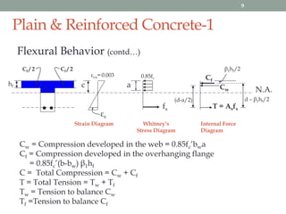
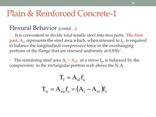
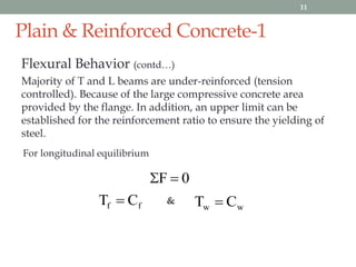
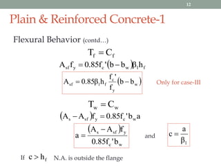
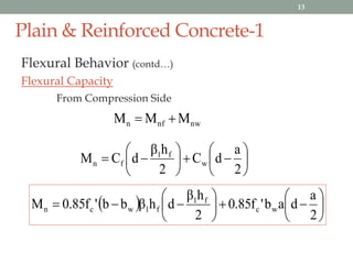
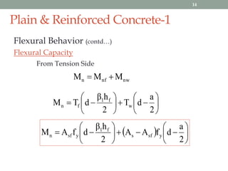
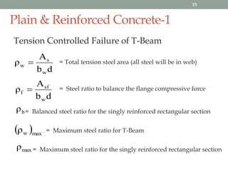
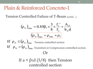

The document provides an analysis of plain and reinforced concrete T and L beams, focusing on their effective widths, flexural behavior, and design considerations. It details the conditions under which beams can be classified based on the position of the neutral axis and discusses various factors affecting tensile and compressive forces within the beams. The analysis includes guidelines for reinforcement ratios and potential failure modes of T-beams.


