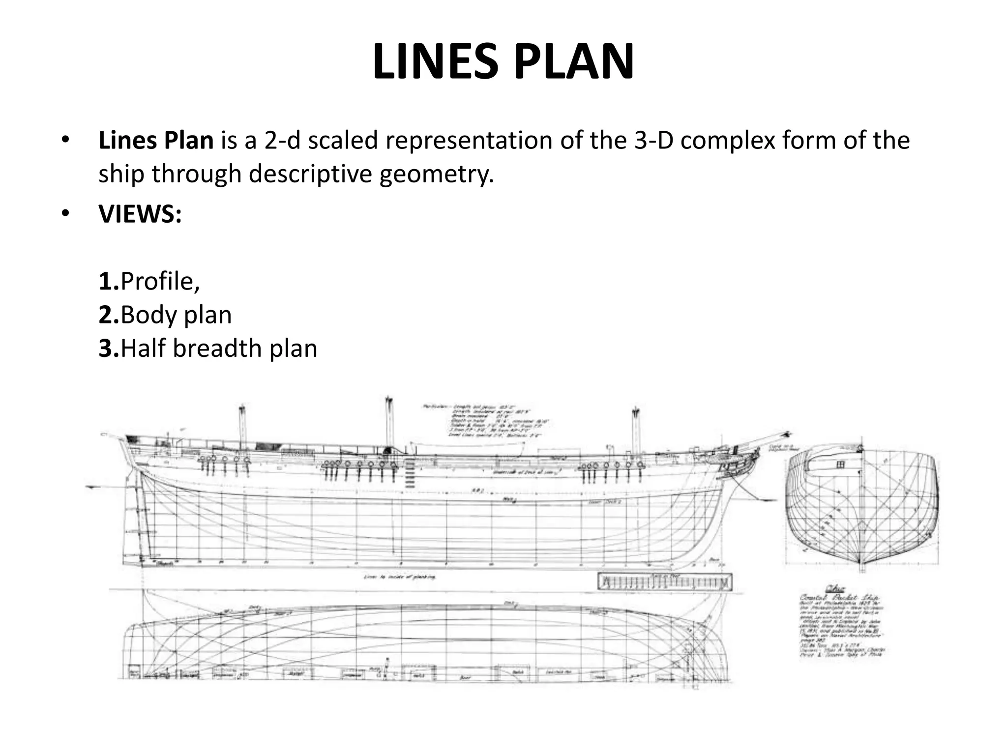
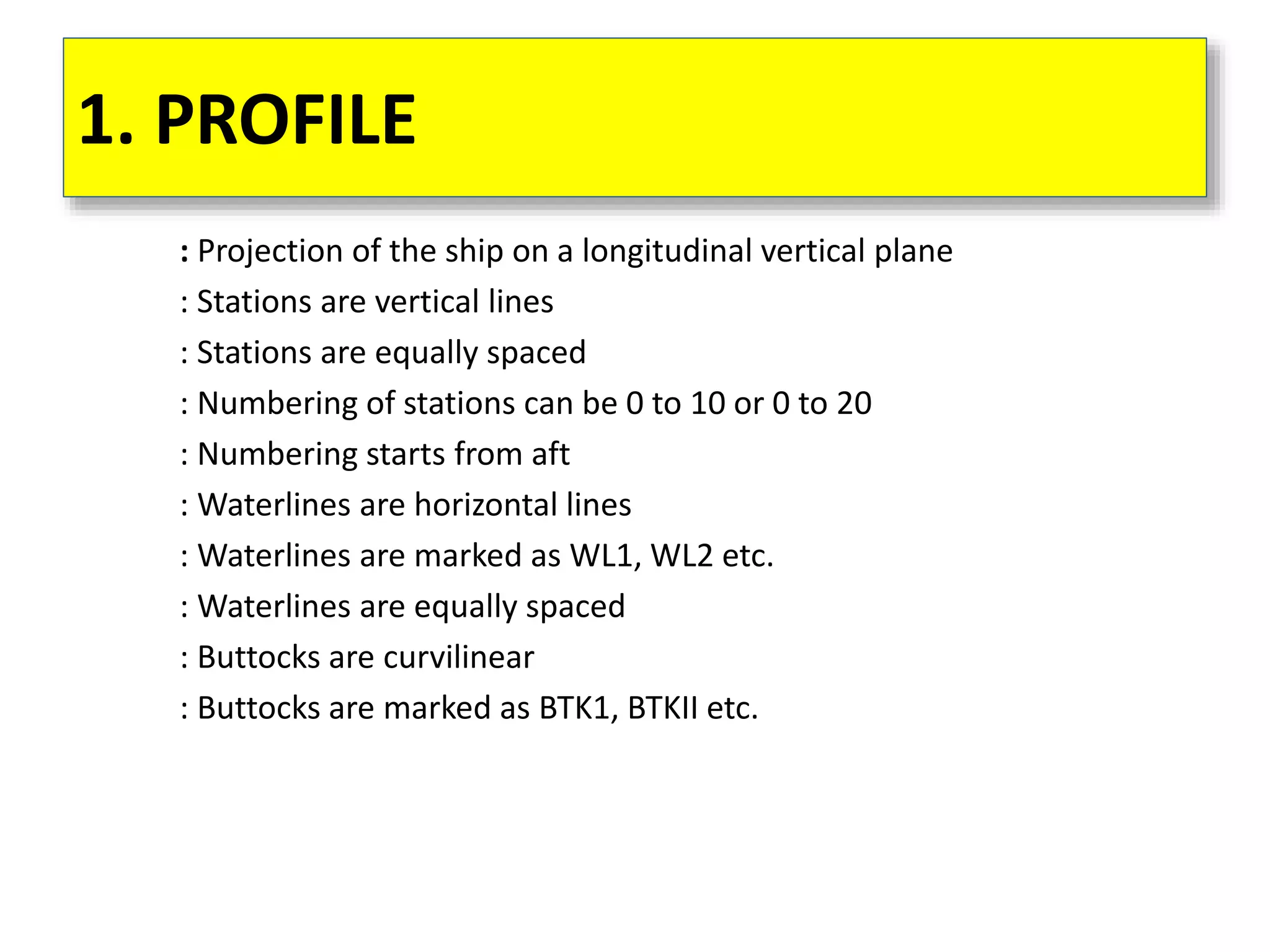
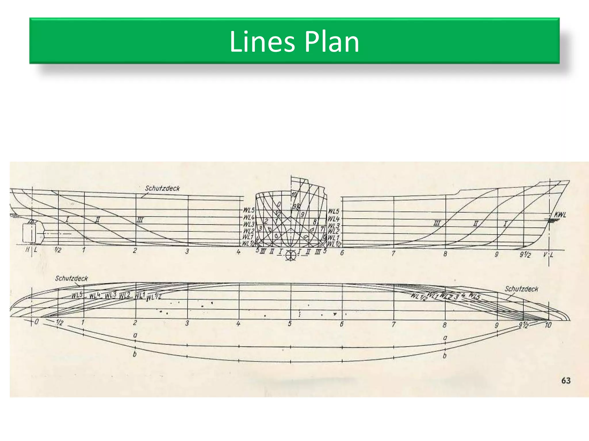
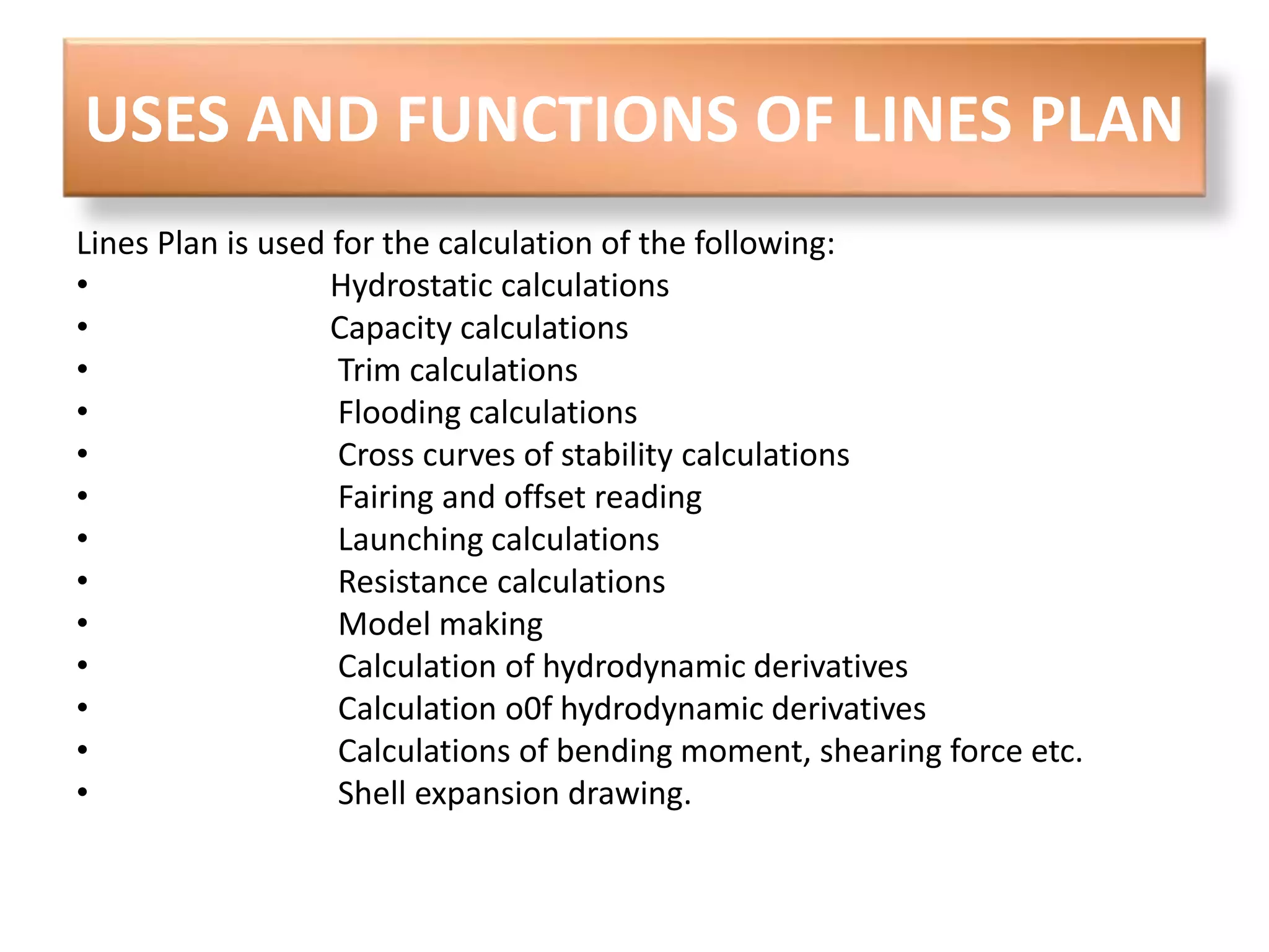
SHIP THEORY 
Basics Of ship geometry : Lines Plan 
By Jishnu Saji , 
Dept. Of Naval Architecture & Ship Building , 
SNGCE , 
Kerala , India
NOTE : 
• This ppt covers the basics of ship theory with 
lines plan and the very basics of ship geometry 
only ,which I had undergone during my first 
course of naval architecture recently . 
• So ,it is recommended to read textbooks for more 
knowledge. 
• Some textbooks I would recommend are : 
1. Basic Ship Theory Volume 1 
2. Principles Of Naval Architecture Vol 1 
• Many Of the Pictures in this ppt is taken from 
internet , courtesy is extended to the sources.
LINES PLAN 
• Lines Plan is a 2-d scaled representation of the 3-D complex form of the 
ship through descriptive geometry. 
• VIEWS: 
1.Profile, 
2.Body plan 
3.Half breadth plan
1. PROFILE 
: Projection of the ship on a longitudinal vertical plane 
: Stations are vertical lines 
: Stations are equally spaced 
: Numbering of stations can be 0 to 10 or 0 to 20 
: Numbering starts from aft 
: Waterlines are horizontal lines 
: Waterlines are marked as WL1, WL2 etc. 
: Waterlines are equally spaced 
: Buttocks are curvilinear 
: Buttocks are marked as BTK1, BTKII etc.
Actual Projection Of Profile view
2. HALF BREADTH PLAN 
: Projection of the ship on a longitudinal horizontal plane 
: Drawn below the profile view 
: Stations are marked as vertical lines 
: Buttocks are drawn parallel to centerline 
: Buttocks are straight lines equidistant from the centerline 
: Waterlines are curvilinear 
: Only half the projection with respect to centerline is drawn 
: No. of waterlines in profile and half breadth plan is same 
: Diagonals are drawn on the other free half
half breadth plan of ship
3. BODY PLAN 
: Projection of the ship on a transverse plane 
: Drawn on the right side of profile 
: Waterlines are horizontal 
: Buttocks are vertical lines 
: The centerline is marked 
: BTK I is closer to centerline 
: Stations are curvlinear 
: Stations from middle to forward are drawn on the right side 
: Stations from aft to middle are drawn on the left side 
: Total number of stations in all views is the same 
: Diagonals are drawn as inclined lines
A computer generated Body Plan
Lines Plan
USES AND FUNCTIONS OF LINES PLAN 
Lines Plan is used for the calculation of the following: 
• Hydrostatic calculations 
• Capacity calculations 
• Trim calculations 
• Flooding calculations 
• Cross curves of stability calculations 
• Fairing and offset reading 
• Launching calculations 
• Resistance calculations 
• Model making 
• Calculation of hydrodynamic derivatives 
• Calculation o0f hydrodynamic derivatives 
• Calculations of bending moment, shearing force etc. 
• Shell expansion drawing.
OFFSET TABLE 
It is a rectilinear tabulation of the following: 
• The heights above base line each section where it is 
crossed by a buttock line. 
• The half breadths at each section where they are 
crossed by waterline. 
__________________________________________ 
Use and functions Of Offset Table 
• For lofting 
• As input to computers for fairing and further 
calculations
A typical OFFSET TABLE
SHIP THEORY : Basics Of Ship Geometry : Lines Plan__by jishnu saji

SHIP THEORY : Basics Of Ship Geometry : Lines Plan__by jishnu saji

  • 1.
    SHIP THEORY BasicsOf ship geometry : Lines Plan By Jishnu Saji , Dept. Of Naval Architecture & Ship Building , SNGCE , Kerala , India
  • 2.
    NOTE : •This ppt covers the basics of ship theory with lines plan and the very basics of ship geometry only ,which I had undergone during my first course of naval architecture recently . • So ,it is recommended to read textbooks for more knowledge. • Some textbooks I would recommend are : 1. Basic Ship Theory Volume 1 2. Principles Of Naval Architecture Vol 1 • Many Of the Pictures in this ppt is taken from internet , courtesy is extended to the sources.
  • 3.
    LINES PLAN •Lines Plan is a 2-d scaled representation of the 3-D complex form of the ship through descriptive geometry. • VIEWS: 1.Profile, 2.Body plan 3.Half breadth plan
  • 4.
    1. PROFILE :Projection of the ship on a longitudinal vertical plane : Stations are vertical lines : Stations are equally spaced : Numbering of stations can be 0 to 10 or 0 to 20 : Numbering starts from aft : Waterlines are horizontal lines : Waterlines are marked as WL1, WL2 etc. : Waterlines are equally spaced : Buttocks are curvilinear : Buttocks are marked as BTK1, BTKII etc.
  • 5.
  • 6.
    2. HALF BREADTHPLAN : Projection of the ship on a longitudinal horizontal plane : Drawn below the profile view : Stations are marked as vertical lines : Buttocks are drawn parallel to centerline : Buttocks are straight lines equidistant from the centerline : Waterlines are curvilinear : Only half the projection with respect to centerline is drawn : No. of waterlines in profile and half breadth plan is same : Diagonals are drawn on the other free half
  • 7.
  • 8.
    3. BODY PLAN : Projection of the ship on a transverse plane : Drawn on the right side of profile : Waterlines are horizontal : Buttocks are vertical lines : The centerline is marked : BTK I is closer to centerline : Stations are curvlinear : Stations from middle to forward are drawn on the right side : Stations from aft to middle are drawn on the left side : Total number of stations in all views is the same : Diagonals are drawn as inclined lines
  • 9.
  • 10.
  • 11.
    USES AND FUNCTIONSOF LINES PLAN Lines Plan is used for the calculation of the following: • Hydrostatic calculations • Capacity calculations • Trim calculations • Flooding calculations • Cross curves of stability calculations • Fairing and offset reading • Launching calculations • Resistance calculations • Model making • Calculation of hydrodynamic derivatives • Calculation o0f hydrodynamic derivatives • Calculations of bending moment, shearing force etc. • Shell expansion drawing.
  • 12.
    OFFSET TABLE Itis a rectilinear tabulation of the following: • The heights above base line each section where it is crossed by a buttock line. • The half breadths at each section where they are crossed by waterline. __________________________________________ Use and functions Of Offset Table • For lofting • As input to computers for fairing and further calculations
  • 13.