Internship Report of Jamshoro Power Company Limited (JPCL)
•Download as DOCX, PDF•
1 like•1,170 views

Jamshoro Power Company Limited Brief Reporting by a student of Chemical Engineering Department Mehran UET.

Recommended
More Related Content
What's hot
What's hot (20)
Similar to Internship Report of Jamshoro Power Company Limited (JPCL)
Similar to Internship Report of Jamshoro Power Company Limited (JPCL) (20)
Recently uploaded
Recently uploaded (20)
Internship Report of Jamshoro Power Company Limited (JPCL)
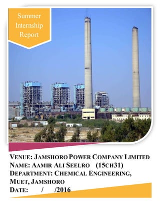
- 1. VENUE: JAMSHORO POWER COMPANY LIMITED NAME: AAMIR ALI SEELRO (15CH31) DEPARTMENT: CHEMICAL ENGINEERING, MUET, JAMSHORO DATE: / /2016 Summer Internship Report
- 2. 1 BACKGROUND This visit aimed to visualize the understanding of the cores of thermodynamics and chemical process technology in the power production sectorunder the supervision of Rizwan Ahmed Arain, the Visit Cordinator. Students, void of engineering applications, developed an insight of the application of processes and learnt about the keys issues of the industry. It brought me plenty of practical works which I’d learnt in my classes PLANT INFRASTRUCTURE AND UNITS. The Plant is installed at the prime location of Jamshoro “The City of Education”, about 18 km away from Hyderabad. It holds the capacity to share an estimated capacity about 850 MW to the national grid of Pakistan. 850 MW is generated by four separate units contributing about 182,155,155 and 157 MW respectively. First plant was commissioned by the Fuji n Electric Company, Japan that only works on Furnace Oil. Other three units were installed by the Chinese firm Harbin Power Electric Engineering that can operate on Gas and furnace oil. This Structure promises to cater the needs of nation efficiently. Structure stood very tall as Pump was installed at ground floor and the boiler at certain elevation and Turbines and turbo generators on the parallel floor. Huge capacity oil containers were protected with sensitivity. The Fuel gas exhaust transported through the sealedtunnels to the high elevation. Two Cooling Water plants were also installed.
- 3. 2 Control Room The control room was operated by the professional operators supervised by operated by the engineers. Power Production Rating measurement systemwas equipped for every separate plant. Fire Fighting System was managed automatically. Activity of shutting down the system was also managed by automated room so called control room. It held all the numerical analysis and graphical data of the pros and cons of the power losses, efficiency and other parameters. Frequently used equipment control switches were mounted on the bench board (where the operator was standing). The back panels contain indicators, recorders, and controls for less frequently operated equipment. Control room had the full governance of operations of the processes involved in the Rankine cycle (thermodynamic cycle) is used in power production industries. The JPCL Plant working lay its basics from the Basic Rankine Reheat Cycles. The Plants basic chemistry involves the pump, the boiler; the turbine and the condenser. Heating Expansion Condensation Power Production Cycles
- 4. 3 The boiler is the main part of any thermal power plant. It converts the fuel energy into steam energy. The fuel may be furnace oil, diesel oil, natural gas or coal. The boilers may be fired from the multiple fuels. The type of boiler used in the JPCL UNIT-I (that our group visited) is “water tube type”. Turbine is used to convert the heat energy into mechanical energy. Turbine used in JPCL is impulse- reaction steam turbine. Water is taken in first to the pump as a saturated liquid and compresses isentropic ally to the operating pressure of the boiler. Temperature Changes and heating in boilers expedites as constant pressure heat additions steams the water. Boiler along with other sections are often called the steam generators. The superheated vapor enters the turbine causing work done on the turbo generators to produce power. Steam now drops off to saturated liquid water mixture and condenses isentropic ally. In between this process, Steam is processed through various special mountings and fittings to ensure safe and efficient functioning.
- 5. 4 Since we are the chemical engineers, so we visited and worked upon the following sections of the power plant. 1. Demi-water plant/ Demineralization plant. 2. Sodium hypochlorite unit. 3. Fuel receiption and testing. 4. Boilers and Chimneys. DEMI-WATER ‘S PLANT/DEMINERALIZATION PLANT: As the name suggests this plant situated in the powerhouse is used to free the water from minerals, like Ca, Mg, Na, Al, Si, K etc. the plant consists of the large tanks where water is stored, Cation and Anion exchange resins, tanks for anion and cation exchange called service tanks and a polisher to polish the demineralized water to cooling towers, in service tank cathode is generated with HCl 7% and anode is generated with NaOH. H+ and OH- ions and minerals are separated and then H+ and OH- are combined to form demi water. SODIUM HYPOCHLORITE UNIT: The unit called sodium hypochlorite unit or sometimes also called chlorination plant provides sodium hypochlorite , a bleaching substance to the demi water in cooling towers as it kills bacteria , removes algae, enables mud to be soluble and limits the contamination in cooling towers. The sodium hypochlorite is produced from brine solution through electrolysis with DC current the water present in solution is directly proportional to voltage and concentration of brine to the current. NaCl+H2ONaOCl+H2 The plant also consists of recirculating tank with rubber coating inside to reduce reactivity between Cl2 and Fe in the tank. Pressure in Being chemical engineer, I worked upon the following sections of JPCL.
- 6. 5 tank (2-4)Pa, electrolyses cells in tank possess flush, the process completes in 45 minutes. FUEL RECIEPTION AND TESTING: Crude oil is used as a fuel for boiler in the powerhouse .crude oil is brought from oil wells on container trucks, it is stored in large tanks of160000 tonnes capacity, but before storage is testedin chemical labs, where viscosity, water %, volatility etc are taken into account, if all things meet the standard values required, then the fuel is stored and used for running the plant. BOILER AND CHIMNEY: Boiler happened to be the large closed vertical vessel, with flame injection the intensity of the flame is maintained according to the requirements, the flame so injected is produced by burning the fuel (crude oil) , the cool demi water tank is capsulated inside the boiler vessel , as its temperature increases the steam is produced which is supplied to the turbine to operate it and the smoke produced in the boiler with flame injections is left to the environment via large chimneys . Process Block Diagram of JPCL Sodium hypochlorite unit Demi water plant Cooling towers Boiler Fuel tank Fuel testing lab Chimney Water from River Indus Smoke to the atmosphere
- 7. 6 Clean, safe water is vital for every day life. Water is essential for health, hygiene and the productivity of our community. The water treatment process may vary slightly at different locations, depending on the technology of the plant and the water it needs to process, but the basic principles are largely the same. This section describes standard water treatment processes applied in JPCL.. Coagulation / Flocculation During coagulation, liquid aluminium sulfate (alum) and/or polymer is added to untreated (raw) water. When mixed with the water, this causes the tiny particles of dirt in the water to stick together or coagulate. Next, groups of dirt particles stick together to form larger, heavier particles called flocs which are easierto remove by settling or filtration. Sedimentation As the water and the floc particles progress through the treatment process, they move into sedimentation basins where the water moves slowly, causing the heavy floc particles to settle to the bottom. Floc which collects on the bottom of the basin is called sludge, and is piped to drying lagoons. In Direct Filtration, the sedimentation step is not included, and the floc is removed by filtration only. Filtration Water flows through a filter designed to remove particles in the water. The filters are made of layers of sand and gravel, and in some cases, crushed anthracite. Filtration collects the suspended impurities in water and enhances the effectiveness of disinfection. The filters are routinely cleaned by backwashing. Disinfection Learnings from Water Pre-treatment Plant (JPCL)
- 8. 7 Water is disinfected before it enters the distribution system to ensure that any disease-causing bacteria, viruses, and parasites are destroyed. Chlorine is used because it is a very effective disinfectant, and residual concentrations can be maintained to guard against possible biological contamination in the water distribution system. Sludge Drying Solids that are collected and settled out of the water by sedimentation and filtration are removed to drying lagoons. Fluoridation Water fluoridation is the treatment of community water supplies for the purpose of adjusting the concentration of the free fluoride ion to the optimum level sufficient to reduce dental caries. Hunter Water is required to fluoridate water in accordance with the NSW Fluoridation of Public Water Supplies Act 1957. pH Correction Lime is added to the filtered water to adjust the pH and stabilise the naturally soft water in order to minimise corrosion in the distribution system, and within customers’ plumbing. End