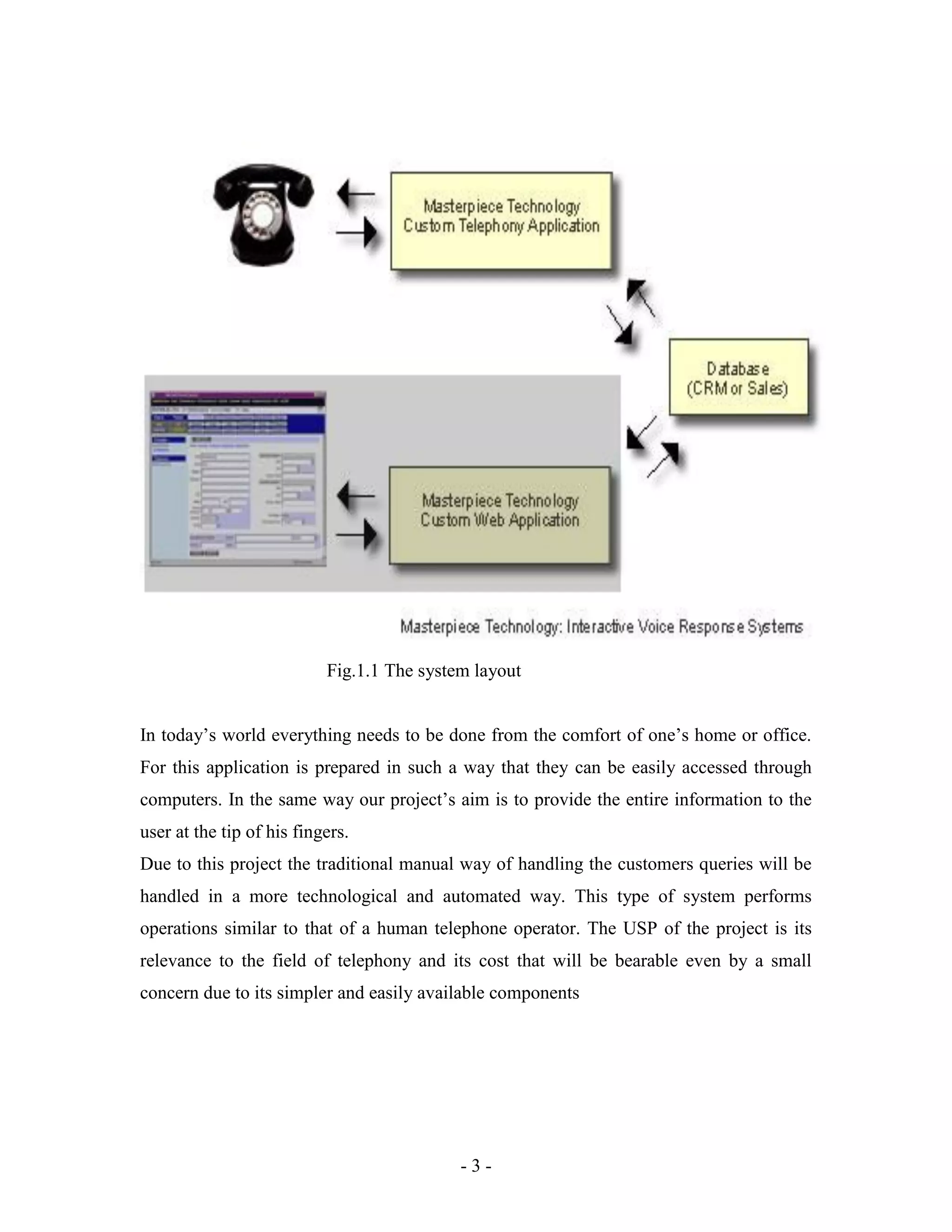
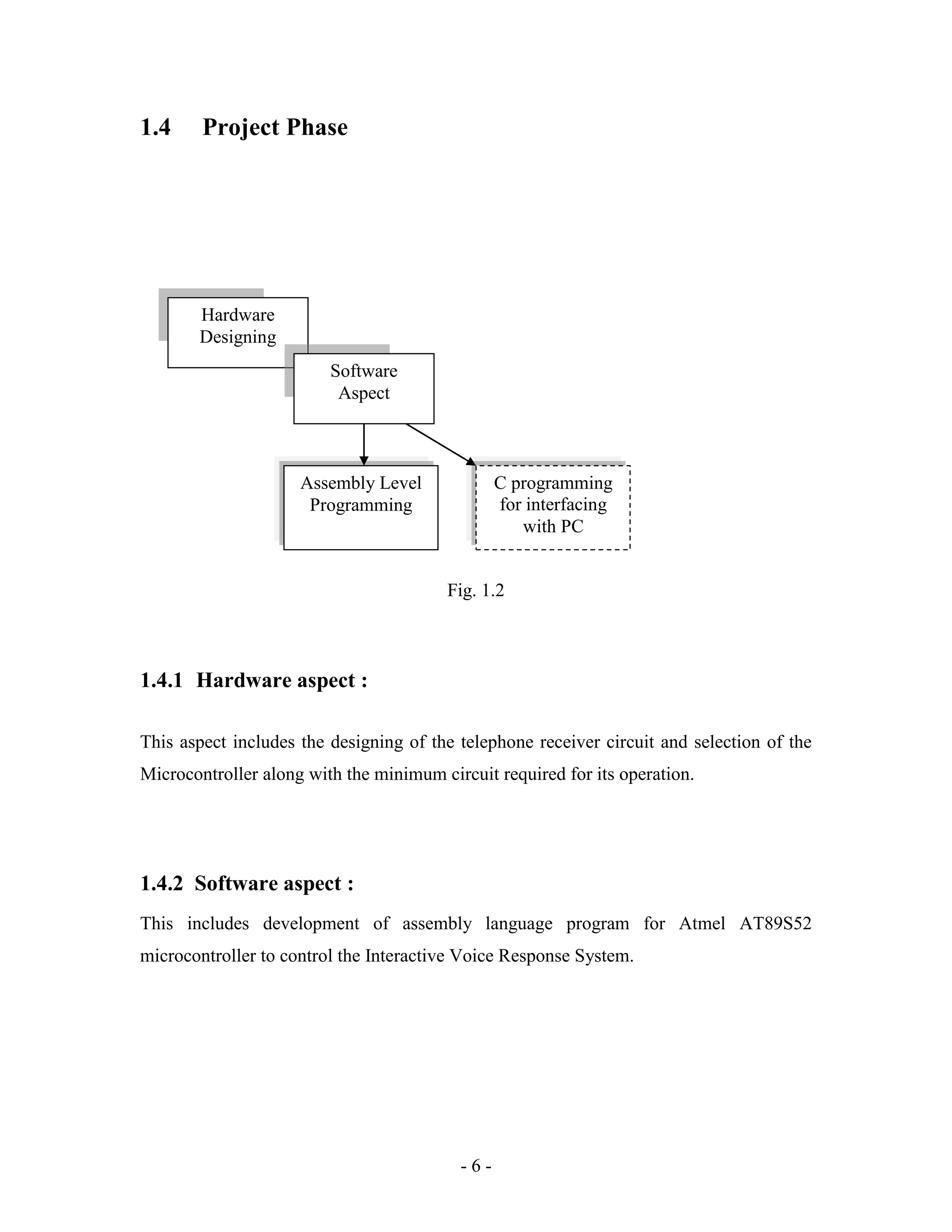
This document is a project report submitted by four students for their Bachelor of Engineering degree. It describes the development of a microcontroller-based interactive voice response system. The system uses a microcontroller and other ICs interfaced to a PC to allow telephone users to access information from a database by following voice prompts. The report includes details of the hardware and software design, component selection, circuit diagrams, programming code and testing procedures. It aims to provide a low-cost alternative to commercial IVR systems for small businesses.
Automotive Adaptive Front-lighting System Reference DesignRimsky Cheng
This document describes a reference design for an automotive adaptive front-lighting system (AFS) that adjusts headlight angle and intensity based on factors like vehicle speed, steering, weather, and motion. The reference design aims to demonstrate an AFS solution using TI microcontrollers. It consists of an AFS controller that communicates over CAN and controls headlights via PWM, and an AFS slave that controls stepper motors to adjust headlight angle via LIN communication. The document provides details on the system architecture and functions of both the controller and slave boards, and guidelines for operating the demo system.
Matrix headlights use an array of individually controllable LEDs and sensors to provide adaptive and precise illumination. They rely on cameras, light sensors and other inputs to allow an onboard computer to dynamically control specific LED segments in real-time, dimming or illuminating them to optimize visibility without glare. This adaptive beam control allows the headlights to safely adapt to different road conditions and traffic. Matrix headlights provide enhanced safety, improved visibility and energy efficiency compared to traditional headlights, and represent the future of automotive lighting technology.
This circuit comprises an infrared (IR) transmitter unit and receiver unit that are mounted on opposite gate pillars. When the IR beam between the units is interrupted, a melody is triggered to sound for 30 seconds from the receiver unit to alert someone that someone is at the gate. The transmitter unit uses a 38kHz IR LED and timer to transmit the IR beam. The receiver unit uses an IR sensor and timer connected to a melody generator IC to detect the beam interruption and play the melody. The units are powered separately but connected to allow the receiver to trigger when the beam is blocked.
This is density based traffic light control system using Programmable logic controller(PLC). Then side which have more vehicles(density) will be getting on first. This process will take place according to number of vehicles.
Smart Agricultural Weed Removal System - A Concept || Mini-Project || Harihar...Hariharan Krishnan
All the images used in my presentation are belonging to their respective owners. I do not own any copyright.
-------------------------------------------------------------------------------------
>> With the Help of open source electronic hardware and software tools, a conceptual model of an Agricultural Weed Removal Robot was developed.
>> Uses Arduino, Supporting Motor Circuitry and some application available on the Google Play Store
>> Two Sections: Motor Drive & Control and Image Processing.
>> Prototype and working part of phase one completed and a research paper was published at Anna University, Tuticorin.
>> Planning to dedicate this project idea to our Indian Farmers, need support and proper technical guidance.
This document outlines a project to implement an automated traffic control system. The system aims to (1) reduce waiting times for lanes with more traffic, (2) maintain proper signal switching with balanced timing, and (3) prevent traffic collisions and allocate timings for pedestrians. The project will use tools like WebSphere Modeler, Eclipse, and DB2 to design traffic signal posts connected to servers configured via Linux. A five-member project team will deliver the system using tasks like assembling infrastructure, installing servers, and gathering usage data for analysis. Upon completion, the final deliverables will include help documentation, application code, database backups, and a full system source code archive.
The document describes a micromouse robot project undertaken by a student team. The team designed and built an autonomous robot to navigate a maze and reach the center in the shortest time possible, for under $500. Key components included a microcontroller to process sensor data and control motors, encoders to track position, and IR sensors to detect walls. The team implemented a PD control system and maze solving algorithm using arrays to navigate. Their micromouse placed 4th out of 20 teams and 3rd out of 15 teams in competitions, completing most of a 256 block maze in under 8 minutes.
Global Advanced Driver Assistance Systems (ADAS) Market: Trends and Opportuni...Daedal Research
The report titled “Global Advanced Driver Assistance Systems (ADAS) Market: Trends and Opportunities (2013-2018)” provides an in-depth analysis of global advanced driver assistance system market. For more mail me: info@daedal-research.com
This document discusses the multidisciplinary product development cycle and deployment of NI-PXI real-time hardware in hardware-in-the-loop simulations. It describes the typical phases of product development including concept, design and development, and validation and verification. It also provides details about using digital prototyping, model-in-the-loop and hardware-in-the-loop simulations using NI-PXI real-time hardware to test control algorithms and identify issues before full deployment. A case study on developing effective flight control systems for an aircraft is presented as an example.
Light Shaping Technologies for Consumer and Automotive Applications 2019Yole Developpement
This report analyzes the market for light shaping technologies used in consumer electronics and automotive applications. It provides market forecasts for optical systems and components from 2018 to 2024 for smartphones, augmented/virtual reality devices, and automotive. It also examines the supply chains and major technology trends in these industries, such as the increasing use of microtechnologies like diffractive optical elements, MEMS scanners, and liquid crystal technologies. The report traces the evolution of these technologies from their origins in technologies that enabled the compact disc in the 1980s to their current applications in smartphones, AR/VR, 3D sensing, LiDAR, and automotive lighting and sensors.
The goal of this project is to optimize traffic light controller in a Metropolitan City by varying the time of Traffic signal lights. The system tries to reduce possibilities of traffic jams, caused by traffic lights, to an extent and give ease to drivers to avoid congested path.
Automatic Number Plate Recognition (ANPR) is a highly accurate system capable of reading vehicle number plates without human intervention through the use of high speed image capture with supporting illumination, detection of characters within the images provided, verification of the character sequences as being those from a vehicle license plate, character recognition to convert image to text; so ending up with a set of metadata that identifies an image containing a vehicle license plate and the associated decoded text of that plate.
The document describes an adaptive lighting system that adjusts a vehicle's headlights based on driving conditions to improve visibility and safety. The system uses a camera and sensors to detect steering angle, oncoming traffic, and vehicles ahead. It then adjusts the headlights to better illuminate corners when turning and prevents blinding other drivers. The system aims to provide better visibility while avoiding causing glare for other motorists.
Presentation of my PhD work about a preliminary design tool for flapping-wing systems. The presentation is about the definition/implementation of an aeroelastic framework that coupled an aerodynamic model of insect flight with a FEM solver, its numerical and experimental validation for preliminary design tasks and finally about its applications to the specific case of a resonant nano-air vehicle: the OVMI. Thus the designers can evaluate quickly the performance of a wing and then determine a wing geometry via an optimization environment. Enjoy!
This document describes a project report for a door knock alarm with timer circuit. It includes an abstract, introduction, theory/principle, circuit analysis, PCB analysis, assembly and testing, working of the circuit, expectations and achievements, project cost, component details, shortcomings and future applications. The circuit uses a piezoelectric sensor to detect door knocks, which triggers a NE555 timer IC to enable a melody generator IC for a set period of time. The music plays through a speaker. The time period can be adjusted with a variable resistor. The project aims to develop a low-cost circuit to alert users when someone knocks on the door.
This document is a major project report submitted by two students, Mahesh Patil and Shivnaresh Likhar, towards fulfilling the requirements for a Bachelor of Engineering degree in Electronics and Communication Engineering. The report describes the development of a "Smart Door" system using embedded systems and microcontrollers. It includes recommendations from professors, a certificate of completion, acknowledgements, an abstract, and table of contents outlining the various chapters which will describe the literature review, analysis, design, implementation, testing and conclusion of the smart door system.
This document is a training report submitted by Indira Kundu to her faculty supervisor, Ms. Pushpa Gothwal, on PLC and SCADA systems. It includes an introduction to automation and PLCs, describing their components, operation, and uses of ladder logic programming. It also covers SCADA systems, their features and applications. The document details two student projects using PLC and SCADA to control LEDs and model a sewage treatment system respectively.
Hirschmann: Automotive SPICE Requirements for development process and tools Intland Software GmbH
The document discusses requirements for development processes and tools based on Automotive SPICE standards. It describes how an automotive company uses various tools like Doors, Trackers, CMDB categories, Wikis and document management to establish bidirectional traceability between requirements, designs, code and tests. URLs and hyperlinks are used to link related artifacts across different tools while maintaining the information in the original tools.
Driver Drowsiness is a grave issue resulting in many road accidents each year. To evaluate the exact number of sleep related accidents because of the difficulties in detecting whether fatigue was a factor and in assessing the level of fatigue is not currently possible. In this paper the camera will be placed besides the rare view mirror of car in way such that it is in clear view of the frontal face of the driver. This camera will continuously capture the video of driver’s frontal face while driving. The system will detect the frontal face in the image and later the eyes. Depending upon the conditions the system will generate an alert. The focus will be on the system that will accurately monitor the open or closed state of the driver’s eyes in real-time. By monitoring the eyes, it is believed that the symptoms of driver fatigue can be detected early to avoid accidents.
Smart Traffic Management System using Internet of Things (IoT)-btech-cse-04-0...TanuAgrawal27
This document presents a final year project report on developing a smart traffic management system using Internet of Things (IoT) technologies. It aims to optimize traffic light timing based on real-time vehicle counting data from road sensors. The proposed system would use sensors, microcontrollers, and cloud computing to monitor traffic flow and congestion at intersections, and dynamically adjust light durations on each lane accordingly. This is expected to reduce traffic delays and minimize commuting costs compared to traditional fixed-time traffic light systems. The report outlines the hardware, software, methodology, algorithms, and challenges of implementing such an IoT-based smart traffic management system.
This document describes a project to tune a DC motor using particle swarm optimization (PSO) and proportional-integral-derivative (PID) control. It includes chapters on PSO, PID control, tuning PID controllers, and applying PSO and PID control to an automatic voltage regulator (AVR) system for a DC motor. PSO is proposed as an optimization method to determine optimal PID gains (Kp, Ki, Kd) for controlling the nonlinear and high-order dynamics of the AVR system. The performance of the PID controller with PSO-tuned gains is found to be better than the classic Ziegler-Nichols tuning method based on analysis of the system's transient response, stability, and frequency
Automatic headlight intensity control systemAmosElliot
This project proposal outlines the design of an automatic headlight intensity control system for vehicles. The system aims to solve the problem of temporary blindness caused when oncoming vehicles use their high beam lights. It will use an LDR sensor and circuitry to detect the bright lights of incoming vehicles and automatically dim the headlights. The objectives are to design a working headlight control circuit, test the circuit performance using software, select components, construct the hardware and software, and test the physical circuit. This system is expected to reduce accidents by minimizing the effects of temporary blindness while driving at night.
“Life’s journey is not to arrive at the grave safely in a well preserved body...Troy Theodore Wruck
“Life’s journey is not to arrive at the grave safely in a well preserved body, but rather to skid in sideways, totally worn out, shouting ‘Holy shit…what a ride!”
~ Hunter S. Thompson
Project report for railway security monotorin systemASWATHY VG
The document discusses railway safety and proposes a railway security monitoring system using vibration sensors and ZigBee technology. It begins with background on railway accidents and the need to improve safety. The existing signaling system relies on human communication, leading to errors. The proposed system uses vibration sensors on trains to detect collisions or derailment. It uses ZigBee for two-way communication between trains and control centers to automatically control railway gates and avert accidents in real-time. The system is expected to improve safety at a low cost without replacing existing infrastructure.
This document is the main project report for a 2D robotic plotter (CNC model) created by four students at the Government Engineering College Idukki. It describes the hardware and software used to build a 2D robotic plotter controlled by an Arduino microcontroller. The plotter uses stepper motors for the X and Y axes and a servo motor to control the pen. Software like Inkscape, CAMotics, Arduino IDE and Processing were used to design drawings, generate gcode files, and program the Arduino. The report provides details of the various components, software programs, and overall design and functioning of the 2D robotic plotter built as part of fulfilling B.Tech degree requirements.
Design and Construction of Digital Locking SystemTarek Erin
This document outlines the design and construction of a digital locking system. It discusses objectives like creating an affordable and effective security system. A literature review covers the history of locks. The methodology describes the system's components like an Arduino, keypad, LCD display and relay interface. A block diagram and circuit diagram show how it works by checking codes and granting access for correct codes. The system was tested and found to work properly. It has applications in industries, buildings and other secure areas. Advantages include improved security while disadvantages include not being economical for multiple locations. The conclusion discusses how technology improves security systems.
This document describes the design of an automated class attendance recording system by Carel van Wyk. The system uses RFID and WiFi technologies to record student attendance. The design includes hardware components like an RFID scanner, LCD display, keypad, and processing board. Software components include a database to store attendance records, memory mapping, LCD layout, and a website for device configuration. Testing was conducted on hardware modules and their integration. Measurements show the WiFi and RFID modules work as intended. The system will integrate with an existing MyStudies application and server to manage attendance records.
This document describes the EnerScope energy management system project. The system aims to integrate various hardware devices and communication interfaces on a common platform. It acquires electricity usage and environmental data from loads like the Experimental Power Grid Centre and a smart home testbed. Data is collected using devices like data acquisition modules, an intelligent energy meter, and wireless sensor motes. These devices communicate through serial, WiFi, and local area network protocols. LabVIEW software is used to retrieve and process the data, which is stored in a database. The system demonstrates real-time energy monitoring and demand response capabilities.
This thesis seeks to improve communication between a host computer and onboard peripherals of an existing low-cost robot used for teaching autonomous systems at University of Innsbruck. Several prototypes were evaluated to find the best solution, including a microcontroller board and single-board computers. The final solution uses an ATmega32 microcontroller programmed to read data from an Android phone and control the robot. Firmware was written for the microcontroller along with an Android application. This improved the robot's modularity and provides easy-to-use interfaces for students.
This document describes a thesis that proposes a multicore architecture allowing fault tolerant cores to distribute critical tasks to less reliable cores. It uses a fingerprinting system where each core monitors others by calculating fingerprints and comparing them in a centralized hardware comparator. The fingerprinting unit represents 15% of core resources while the comparator adds 6% cost. An FPGA prototype was developed to fingerprint parallel thread executions. A virtual debugging platform was also created using processor models and multicore simulation.
A typical design flow follows the below structure and can be broken down into multiple steps. Some of these phases happen in parallel and some in sequentially.
Requirements
A customer of a semiconductor firm is typically some other company who plans to use the chip in its systems or end products. So, the customer's requirements also play an important role in deciding how the chip should be designed.
The first step is to collect the requirements, estimate the end product's market value, and evaluate the number of resources required to do the project.
Specifications
The next step is to collect specifications that describe the functionality, interface abstractly, and over all architecture of the chip to be designed. This can be something along the lines such as:
Play
Next
Unmute
Current TimeÂ
0:00
/
DurationÂ
18:10
Â
Fullscreen
Backward Skip 10s
Play Video
Forward Skip 10s
Requires computational power to run imaging algorithms to support virtual reality.
Requires two ARM A53 processors with coherent interconnect and should run at 600 MHz.
Requires USB 3.0, Bluetooth, and PCIe 2nd gen interfaces.
It should support 1920x1080 pixel displays with an appropriate controller.
Digital Design
Because of the complex nature of modern chips, it's impossible to build something from scratch, and in many cases, many components will be reused.
For example, company A requires a FlexCAN module to interact with other modules in an automobile. They can either buy the FlexCAN design from another company to save time and effort or spend resources to build one.
It's not practical to design such a system from basic building blocks such as flip-flops and CMOS transistors.
Instead, a behavioral description is developed to analyze the design in terms of functionality, performance, and other high-level issues using a Hardware Description Language such as Verilog or VHDL.
This is usually done by a digital designer and is similar to a high-level computer programmer equipped with digital electronics skills.
Verification
Once the RTL design is ready, it needs to be verified for functional correctness.
For example, a DSP processor is expected to issue bus transactions with fetching instructions from memory and know that this will happen as expected.
The functional verification is required at this point, which is done with EDA simulators' help that can model the design and apply a different stimulus to it. This is the job of a pre-silicon verification engineer.
Logic Synthesis
Now we will convert this design into hardware schematic with real elements such as combinational gates and flip-flops. This step is called synthesis.
Logic synthesis tools enable the conversion of RTL description in HDL to a gate-level netlist. This netlist is a description of the circuit in terms of gates and connections between them.
Logic synthesis tools ensure that the netlist meets timing, area, and power specifications. Typically, they have access to different technology node
This document is a thesis submitted by Matthew L. Barrett to the University of Wollongong for the degree of Bachelor of Engineering (Mechatronic). The thesis describes the design and development of an electromechanical disk brake calliper for an electric vehicle. Key points:
- The calliper design is based around a ball ramp actuator powered by an electric motor through a planetary gearbox.
- A test bed was developed to experimentally test the electromechanical brake calliper and evaluate its performance under different control strategies. This includes using a momentum simulation to model the mass of a vehicle braking.
- The project aims to contribute to research on electromechanical braking and ball ramp actuators, which currently
Increasing technology development and better life standards of the mod-
ern society demand more stable, top quality electricity. In meeting these
demands the high voltage industry has been adding new technology to its
equipment in order to maximize its efficiency. This is often the only option
available as it is not always possible to add more power plants or transmis-
sion lines especially in populated areas where the need for more power is
perhaps the greatest.
One of those new technologies implemented in the modern power system
is the Phasor Measurement Unit (PMU). In general the main purpose of
the PMU is to synchronize measurements at different locations in the power
grid by using the GPS technology. This technology is called Wide Area
Measurement System (WAMS).
Development of the PMU is well on its way in several countries, e.g. in
USA they have developed technology called Wide–Area Stability and Volt-
age Control System (WACS), where they can receive and analyze measure-
ment data live [7]. An obvious advantage of that is the ability to foresee
a fault and thus the capability to take the necessary measures to minimize
the fault’s effect on the system or even stop the fault from occurring.
This document is a master's thesis submitted by Milan Tepić to the University of Stuttgart exploring host-based intrusion detection to enhance cybersecurity in real-time automotive systems. The thesis was supervised by Dr.-Ing. Mohamed Abdelaal and examined by Prof. Dr. Kurt Rothermel. It explores using timing elements of control unit functions to detect anomalies and intrusions. The goal is to develop a host-based intrusion detection system called AutoSec that can detect anomalies while keeping false alarms close to zero, in compliance with the AUTOSAR automotive software standard.
This document describes a student project to implement database systems on the SpiNNaker neuromorphic hardware architecture. The student developed a key-value store and relational database to run on SpiNNaker, evaluating its performance and limitations for general purpose computing. The conclusions from this work provide feedback that could help improve SpiNNaker's design for applications beyond neural network simulations. Challenges included dealing with unreliable communication, out-of-order execution, and API bugs in the neuromorphic system. Evaluation benchmarks analyzed reliability, throughput, and memory usage under the database workloads.
This thesis examines parameters identification of a permanent magnet DC motor. Chapter 1 introduces the research motivation and literature review on identification methods. Chapter 2 covers DC motor principles and common identification techniques like pseudo inverse, nonlinear least squares, and pattern search. Chapter 3 details the hardware design including MOSFET switches, PWM, and sensors. Chapter 4 presents experimentation, testing, and identification results using MATLAB/Simulink. The motor parameters are estimated using nonlinear least squares and pattern search methods. A GUI is designed for automation and student use. Chapter 5 provides conclusions and discusses future work such as improving accuracy and automating more of the process.
This document describes the development of a magnetic component design environment. It includes the development of an automated core loss measurement system to characterize magnetic materials, a database to store measurement data, and a design software tool. The core loss measurement system allows for easy and automated measurement of core loss over a range of frequencies and flux densities. Measured data is stored in a database, which can be accessed by the design software to enable accurate prediction of core losses during the design process. Validation measurements on inductors showed errors between predicted and measured losses and temperatures were less than 10%, demonstrating the effectiveness of the design environment for improving magnetic component design.
This masters report describes the COAcHMAN project which aims to simplify user interactions with smart homes through context awareness. The report conducts background research on context awareness and home automation technologies. As a result, a software solution called COAcHMAN is proposed which enables homes to react based on the user's context rather than requiring direct user interaction. COAcHMAN integrates with the openHAB home automation platform and uses online user profiles to provide familiar interfaces for users. The implementation of COAcHMAN is described along with further development areas like authentication and using internal sensor data.
This document provides instructions for setting up and using Wireless M-Bus devices with the Wireless M-Bus Suite software. It describes the hardware and firmware setup, including supported radio modules, required resources, and how to install firmware. It also provides a quick start guide for using the Wireless M-Bus Suite to test devices, including how to set the COM port, load a demo project, use the collector and meter modes, and perform tests like pinging. Additional chapters cover the Wireless M-Bus protocol monitor for analyzing network packets and a demonstration application.
This document is a minor project report submitted by Shahrukh Mohd Ayyaz Khan to the Department of Computer Engineering at SSBT's College of Engineering and Technology in partial fulfillment of the requirements for a Bachelor of Engineering degree. The report details the development of a Local Area Network Manager application. It includes sections on system analysis, requirements specification, system design, implementation, testing, results and analysis, and conclusions. Diagrams and screenshots are provided to illustrate various aspects of the system architecture, design, and functionality.
Implementation of a Localization System for Sensor Networks-berkleyFarhad Gholami
This dissertation discusses the implementation of a localization system for sensor networks. It addresses two main tasks: establishing relationships to reference points (e.g. distance measurements) and using those relationships and reference point positions to calculate sensor positions algorithmically.
The dissertation first presents various centralized and distributed localization algorithms from existing research. It then focuses on implementing a distributed, least-squares-based localization algorithm and designing an ultra-low power hardware architecture for it. Measurement errors due to fixed-point arithmetic are also analyzed.
The second part of the dissertation proposes, designs and prototypes an RF signal-based time-of-flight ranging system. The prototype achieves a measurement error within -0.5m to 2m at 100
Maxime Javaux - Automated spike analysisMaxime Javaux
This document summarizes Maxime Javaux's master's thesis conducted at the University of Liège for Melexis to develop an automated spike analysis tool for integrated circuit production testing. The tool aims to detect undesirable high frequency voltage spikes during testing that could damage components, and to localize the source of any spikes found. To achieve this, the thesis designed analog circuit boards to detect spikes and interface with an oscilloscope for data acquisition. It also created a computer program to synchronize the test equipment, acquire and analyze waveforms, and identify which tests produce spikes. The completed tool allows test engineers to more efficiently debug spike issues, reducing analysis time from days or weeks to just hours.
This document describes a project to design and implement an OFDM-based wireless transmitter compliant with the IEEE 802.11g standard on an FPGA. The transmitter was modeled using Simulink and the model was tested through cosimulation and using EDA tools. Testing showed the design met timing requirements and error measurements were satisfactory, demonstrating a successful OFDM transmitter design using a model-based approach.
This document is a final report from 1993 on modelling and designing scalable parallel computing systems. It details the development of a fractal parallel computer topology that can extend to fill a wafer. Algorithms were developed for routing and load balancing, and a simulation program tested a 64-node network using UNIX and PC workstations. Benchmarking of a 16-node example network demonstrated scalability. The report discusses implementing hardware control to support applications using wafer-scale integration.
This document presents a dissertation on designing and implementing a 3D hand tracking interface using the Nintendo Wii Remote. It begins with an introduction describing the background and objectives of the project. It then provides a literature review on the Wii Remote's capabilities and technical specifications. The document outlines several conceptual models for hand tracking with increasing degrees of freedom. It presents the implementation of a 6 degree of freedom hand tracking system using two IR light sources and the Wii Remote's infrared camera. Testing and results demonstrate that the system allows for fast and accurate 3D tracking of hands at low cost, with potential applications for molecular visualization and other CAD programs.
1. - i -
MICROCONTROLLER BASED
INTERACTIVE VOICE RESPONSE
SYSTEM
PROJECT REPORT SUBMITTED IN PARTIAL FULFILLMENT OF THE
REQUIREMENTS
FOR THE DEGREE OF
BACHELOR OF ENGINEERING (EXTC)
OF
THE UNIVERSITY OF MUMBAI
BY
SWAPNIL MADALI
HARSH MEHTA
PRANOY BALAKRISHNAN
ABHISHEK NADKARNI
ELECTRONICS AND TELECOMMUNICATION DEPARTMENT
ATHARVA COLLEGE OF ENGINEERING
MALAD MARVE ROAD, MALAD (W), MUMBAI - 400059
2007-2008
2. - ii -
PROJECT REPORT
ON
MICROCONTROLLER BASED INTERACTIVE VOICE RESPONSE SYSTEM
SUBMITTED BY:
SWAPNIL MADALI
HARSH MEHTA
PRANOY BALAKRISHNAN
ABHISHEK NADKARNI
UNDER THE GUIDANCE OF
PROF. ARCHANA GAWAD
(INTERNAL GUIDE)
ELECTRONICS AND TELECOMMUNICATION DEPARTMENT
ATHARVA COLLEGE OF ENGINEERING
MALAD MARVE ROAD, MALAD (W), MUMBAI - 400059
2007-2008
3. - iii -
CERTIFICATE
ATHARVA COLLEGE OF ENGINEERING
Malad Marve Road, Malad (W), Mumbai - 400059
This is to certify that the following students of
Electronics and Telecommunication Department
SWAPNIL MADALI
HARSH MEHTA
PRANOY BALAKRISHNAN
ABHISHEK NADKARNI
have submitted the project report titled MICROCONTROLLER BASED
INTERACTIVE VOICE RESPONSE SYSTEM in the partial fulfillment of the
requirements for the Degree of Bachelor of Engineering (EXTC) satisfactorily.
Prof. Archana Gawad Dr. A.M. Salsingikar Prof. A. Deshpande
( Internal Guide ) ( Head Of Department of EXTC ) ( Principal )
4. - iv -
Acknowledgement
The purpose of this project has been to make the maximum use of the dexterity
we possess and polish our ideas before we enter into this gruesome world of
industrial development. In our attempt we have been endlessly supported by our
internal guide. We would like to thank our internal guide Prof. Archana Gawad
who encouraged us to go ahead with this project and have provided us with
valuable help when needed and who has also been instrumental in providing us
the ideas to go about the project and has been constantly monitoring our progress.
We would like to express our gratitude to the Head of our Department Dr. A.M.
Salsingikar for his timely support and the Principal of Atharva College Of
Engineering Prof. A. Deshpande for her encouragement. We intend to put in our
best efforts with the view of achieving optimum result
APRIL 15, 2008 Swapnil Madali
Harsh Mehta
Pranoy Balakrishnan
Abhishek Nadkarni
5. - v -
Abstract
The Interactive Voice Response (IVR) System serves as a bridge between people
and computer databases by connecting the telephone network with the database.
The telephone user can access the information from anywhere at anytime simply
by dialing a specified number and following an on-line instruction when a
connection has been established.
The IVR system uses pre-recorded or computer generated voice responses to
provide information in response to an input from a telephone caller. The input
may be given by means of touch-tone or Dual Tone Multi-Frequency (DTMF)
signal, which is generated when a caller presses a key of his/her telephone set,
and the sequence of messages to be played is determined dynamically according
to an internal menu structure (maintained within the IVR application program)
and the user input.
The IVRS system which will be designed will provide an ideal platform for the
operation of start-ups and existing small concerns. It will be a highly economical
and efficient way to replace the Dialogic card which is very costly and requires a
high maintenance and regular up gradation.
The IVRS system which will be designed will consist of simple components like
microcontroller and some basic application chips interfaced to a PC which will
have a small software running in the backend while the other jobs are performed
on the front end.
13. - 2 -
1.1 Overview
The beginning is always an uncertain phase for the students when it comes to the
selection of their final year project. The project forms the very important part of the
curriculum as it gives the students very comprehensive hand s of experience on real time
tasks. The trickiest part of the job is the selection of the topic of the project. Since the
branch of Electronics and Telecommunication Engineering offers a wide range of
projects it is rather difficult to choose the best one for you. We, as the group of four
students thought of something, which would allow us to implement the theories we had
learned in class. We decided to work on the system, which would have microcontroller
along with a PC as a fundamental control block of the design. Having established the
field of work it was now left to decide on the exact project to work on. After numerous
discussions with the college professors and the field experts in the organization we had
approached we decided to work on a project, which would take relevance of the branch of
engineering we enrolled in. Thus we decided to work on the IVRS system, the title of the
project being INTERACTIVE VOICE RESPONSE SYSTEM.
Since we were inclined to put into use the knowledge gained in classroom we agreed on
using a microcontroller to serve the desired purpose. The project is to establish the
continuity of the database stored in a local computer (in wave format) with the telephone
line by the development of the MICROCONTROLLER BASED INTERACTIVE
VOICE RESPONSE SYSTEM without any human interface.
14. - 3 -
Fig.1.1 The system layout
In today’s world everything needs to be done from the comfort of one’s home or office.
For this application is prepared in such a way that they can be easily accessed through
computers. In the same way our project’s aim is to provide the entire information to the
user at the tip of his fingers.
Due to this project the traditional manual way of handling the customers queries will be
handled in a more technological and automated way. This type of system performs
operations similar to that of a human telephone operator. The USP of the project is its
relevance to the field of telephony and its cost that will be bearable even by a small
concern due to its simpler and easily available components
15. - 4 -
1.2 Motivation
Initially we thought of realizing the project with the help of normal voice modem but
due to that the project would have been an entire software oriented project.
We always wished to work on a project that would have some commercial value and
one could put it in some possible use.
We were keen on including both software and hardware aspects in our project and so
we planned accordingly.
We wished to do something that would save precious time and increase the efficiency
of the project without much of arduous work.
The system planned by us was a PC based one, so that, the system could be controlled
by a single user without any hassles.
We wanted the project to be based on theories related to our branch of engineering
and planned accordingly.
16. - 5 -
1.3 Aim of the Project
“Need is the mother of all inventions”
As this proverb goes everything which is discovered has some history regarding its need
at some point of time. The Interactive Voice Response system has traditionally been used
as a very efficient and logical alternative to a human enquiry.
The most common IVRS system uses a Dialogic card. The dialogic card is the heart of all
the existing Interactive Voice Response system and rightly so is the most costly
component within the system. Going by the current market price (based on extensive
research), an average dialogic card cost around $4000 which is grossly equal to
Rs.1,60,000 (which is quite exorbitant!).
Whenever an organization or a company wishes to employ an Interactive Voice Response
system it has to be ready with a high price to fulfill its need. This is where the main
application of our project comes into picture. Our project aims to reduce the cost of the
Interactive Voice Response system in a very logical manner by replacing the dialogic
card with a microcontroller (considerably cheap).
But as with all good things we have to compromise with something. Here, the
compromise is with respect to the number of calls that can be handled at any given time
i.e. the load handling capacity is considerably reduced. To be specific our project aims to
help the startup and small concerns who don’t invite heavy callers at any given time.
India being a developing country is seeing the emergence of entrepreneur who has the
required talent but not the capital. Our project is targeted to help these budding
entrepreneurs in their nascent stage and thus help them to blossom and expand their
horizon.
17. - 6 -
1.4 Project Phase
Fig. 1.2
1.4.1 Hardware aspect :
This aspect includes the designing of the telephone receiver circuit and selection of the
Microcontroller along with the minimum circuit required for its operation.
1.4.2 Software aspect :
This includes development of assembly language program for Atmel AT89S52
microcontroller to control the Interactive Voice Response System.
Hardware
Designing
Software
Aspect
Assembly Level
Programming
C programming
for interfacing
with PC
18. - 7 -
1.4.2.1 Basic features to be simulated :
The following features will be incorporated into the system as a high priority task.
VCC: Virtual Calling Card
FPH: Free Phone Service
TVT: Tele Voting
ACC: Account Calling Card
1.4.2.2 Advanced features of the system :
The following features will be developed after the basic features are simulated
Registering the complain
Registration for new connection
Status of complain
Status of new connection
Automatic connection to the local linesman
Connect to the operator
The Troubleshooting aspect will be followed at every step during the course of the
project.
19. - 8 -
1.5 Organization of the Report
This report is a compilation of the Project work undertaken during the Seventh Semester
of the Engineering degree course in Electronics and telecommunications and the data
collected during the period in order to achieve the final objective of a successful project.
Chapter 1 introduces the topic of the project. This chapter traces the evolution of the IVR
systems and describes the motivation and also gives the phases of the project. It also
broaches our proposed work.
Chapter 2 discusses the basic block diagram of our IVRS and gives a block by block
description of each part of the diagram also specifying the components involved. It also
enlightens the circuit diagram and the entire technical working of the project.
Chapter 3 gives the system flow graph as to what will be the flow of the design system
and its algorithm at the user end and similarly the flow diagram and algorithm at system
end.
Chapter 4 introduces the various important IC which includes the microcontroller 89s52,
DTMF decoder 8870, voice chip APR9600 as well as other ICs like 4047,6N139,7400,
LM7805 & LM7812 which form the external circuit.
Chapter 5 glosses over the printed circuit board giving the pictorial view as well as the
path connecting the components in the positive and negative films.
Chapter 6 introduces the software aspect of the project. It begins with the basic block
diagram which tells us the basic flow of the software. It proceeds with the description of
the software which gives us the meted logy and the nuances involved in the software
triggering the hardware.
20. - 9 -
Chapter 7 is involved with the information about the various trouble shootings which
were encountered during the testing phase of our project.
Chapter 8 gives the list of the components which were involved in realizing the circuit. It
also broaches the estimated cost of the components. Thus valuating the entire project.
Chapter 9 includes the conclusion drawn on the basis of the work done through out the
year and is a blue print of the entire project highlighting the various stages of the projects.
Chapter 10 includes the future scope of the project with respect to the integration of the
primary PCB to the computer via serial communication.
Reference Section lists the plethora of books referred and websites visited in an effort to
compile this report in addition to the various decisions taken about the various critical
features of the project.
Appendix includes the various data sheets as given by the companies.
22. - 11 -
2.1 Basic Block Diagram
Fig 2.1
Isolation
Transformer
RS232
Cables
Computer
MAX232
Chip
Micro
Controller
89C52
Telephone
Line
Voice
chip
Ring
Detector
DTMF
Decoder
8870
Relay
Control
Relay
control for
Audio
Relay
Activation
Circuit
23. - 12 -
2.2 Description of Blocks
2.2.1 TELEPHONE TO MICROCONTROLLER
The basic blocks of this part of the system consist of:
1. Ring Detector
2. Relay Activation Circuit
3. A DTMF Decoder
4. A Relay Control For DTMF Decoder
5. Microcontroller
2.1.1 Ring Detector:
The ring detector first detects the incoming signal. A bridge rectifier is connected to the
telephone line. This turns the ringing signal (an alternating voltage) into a pulsating
direct voltage that is smoothened by the condenser and limited with the aid of zener
diodes. The direct voltage across the zener diode is applied to the opto-coupler that
forms as the electrical isolation between the two stages.
2.1.2 DTMF decoder:
The DTMF decoder 8870 performs the function of decoding the digits dialed by the user
in their corresponding binary states and thus making them available for processing in the
microcontroller.
24. - 13 -
2.1.3 Relay circuits:
We are using two relays that will be performing various tasks as follows:
Relay to control DTMF decoder:
This relay is used to activate and deactivate the 8870 DTMF decoder at various strategic
points. It activates the DTMF decoder just before the user is about to dial the digit. It
deactivates the 8870 DTMF decoder immediately after the user has dialed the digit.
Relay to control feedback audio:
This relay is used to connect and disconnect the audio feedback line (explained later)
with the main telephone line after the response from the user is been received.
Relay activation circuit:
This forms the heart of the relay circuits as it controls the functioning of relay according
to the inputs it receives from the microcontroller.
2.2.2 Microcontroller to telephone (via Voice chip)
The basic blocks of this part are
1. Microcontroller
2. Voice chip
25. - 14 -
Microcontroller: this is brain of this part. In this part triggers the appropriate channels i.e
the message in the voice chip based on the instant the receiver is lifted and based on the
response of the user.
Voice chip: this forms the heart of this module (definitely of the circuit as well). The
voice chip along with its external circuitry has the provision to work in the two message,
four message or the eight message mode. This circuitry has a microphone which enables
the storing of any message by directly introducing the speech signal. The proper method
of storing the signal can be obtained from the data sheet of the voice chip included later.
The audio output can be directly taken from the bridge and is given to the telephone wire
itself. Since the obtained audio signal is a very low amplitude signal, it does not interfere
with the normal working of the telephone line.
2.2.3 MICROCONTROLLER TO TELEPHONE (VIA COMPUTER)
The basic blocks of this part of the system consist of:
1. Signal Converter
2. Computer
3. Isolation Transformer
4. Microcontroller
2.2.1 Signal converter:
The function of this block is to convert the output of the microcontroller into the
signal that is compatible enough to be input of the computer. This is done by using
max 232 chip and RS 232 cables. The signal at the output of the microcontroller is of
the range of 0v to 5v. It is converted into a signal in the range of –12v to +12v to be
input to the PC.
26. - 15 -
2.2.2 Computer:
The computer performs the function of sending the proper wave file according to the
input it receives from the microcontroller. There are various respective wave files
stored in its memory which are according to the output depending on the user request.
2.2.3 Isolation transformer:
This is the very important block as it isolates the computer with the high voltage
telephone line (having a potential difference of –60v). The isolation transformer used
is 1:1 600 ohms. The primary is connected to the output of the computer and the
secondary is connected to the feedback telephone line and controlled by relay circuits
(mentioned earlier).
2.2.4 Microcontroller:
This forms the heart of our entire INTERACTIVE VOICE RESPONSE SYSYTEM.
It is a common block to both the parts. It accepts a suitable signal from ring detector
circuit and triggers the relay activation circuit.
It also accepts the output of 8870 DTMF decoder and processes it and gives the
suitable signal to the computer. It controls the working of various functional blocks
and co-ordinates the operation.
29. - 18 -
2.5 Description of Circuit
The initial part of the circuit is the ring detector circuit. The job of the ring detector
circuit is to detect the ringing signal and inform the microcontroller about it. At the same
time the ring detected is being informed to the mono stable multivibrator whose job is to
detect the error pulsing or error signaling. As soon as the ring is detected by the ring
detector circuit the output pin of the ring detector goes high and low in accordance with
the incoming ringing signal indicating that the subscriber is trying to access the system.
The ring is detected at the output of the ring detector at pin no5. This output pin of the
ring detector is connected to the pin number 26 of the microcontroller. The job of this pin
is to indicate the microcontroller about the ringing signal. This pin number 26 also goes
high and low in accordance with the incoming ringing signal. This is the stage from
which our assembly language program burnt into our microcontroller starts executing.
The first job of our program is to count the total number of high and low signals at pin
number 26 of the microcontroller. We have programmed our chip to count up to five high
and low signals received from the ring detector circuit so that no false triggering occurs.
A 10 secs delay is called in the program to detect false triggering. If the subscriber trying
to access the system disconnects the call during this 10 secs delay the program is
automatically terminated and the program once again waits for the incoming ringing
signal. If the ringing signal exist after the end of 10 secs delay. Then the incoming signal
is acknowledged by the microcontroller and thus the microcontroller makes pin no 5
active high. This makes relay1 to be connected and the microcontroller ensures that the
line is connected or rather the line is picked up.
Initially when the handset is not picked up the voltage level across the ring and the tip
line of the telephone is 53V. When the ring comes there is a fluctuation in the voltage.
When the handset is picked up the voltage becomes 25V. This is the step in our system
in which the caller gets connected to the system.The beauty of the circuit is that it creates
a telephone like condition inspite of the absence of one and the entire procedure in
automatic.
30. - 19 -
Once the caller is connected the next step is to immediately reply the caller with an
welcoming message. This is done by the microcontroller by making pin no 15 active
high. This will connect our second relay which is the audio relay in our circuit. Once this
relay is connected the welcoming message is to be played to the caller immediately. To
initialize this, pin no P2.0 in made active low.
Here comes the functioning of our voice chip pcb which is connected to our primary pcb
via port2 of the microcontroller.
32. - 21 -
3.1 Flow Chart ( System End )
Ring Signal
detected?
Start
Ring
Continue?
Wait for 10 seconds
Deactivate DTMF
decoder by relay ckt.
Wait for user response
Establish a
dedicated line
Activate Relay to ans.
Pass the audio via the
isolation transformer.
Call terminate
Continue?
Yes
No
No
No
Yes
Yes
Stop
33. - 22 -
3.2 Algorithm ( System End )
Step 1 : Dial the number for the Interactive Voice Response System.
Step 2 : Check for the received signal.
Step 3 : If Busy Tone then go to step 4 else go to step 5.
Step 4 : Terminate the call check for redial. If yes go to step 4 if no go to step 10.
Step 5 : Wait for call to be answered.
Step 6 : On being answered dial for the language in which to be answered.
Step 7 : Choose the service for the required information.
Step 8 : Check if you want to continue. If yes go to step 7, if no go to step 9.
Step 9 : Terminate the call.
Step 10 : Stop the system.
34. - 23 -
3.3 Flow Chart ( User End )
YES
YES NO
Start
Dial the Number.
Check the
signal
Dial for
Language.
Wait to be
answered.
Ringing
Signal
Call
Terminate
Busy Tone
Stop
Redial?
Choose for
the service.
Continue?
Call
Terminate
Stop
NO
Fig 3.2
35. - 24 -
3.4 Algorithm ( User End )
Step 1 : Check if the ringing signal is present in the telephone line.
Step 2 : If ringing signal is present then wait for 10 seconds, & go to step 3 or else go to
step 1.
Step 3 : If ring continues then activate the relay or else go to step 1.
Step 4 : Establish a dedicated line connection.
Step 5 : Wait for the response of the caller.
Step 6 : Deactivate the DTMF decoder by relay control circuit to save the decoder from
getting false input.
Step 7 : Pass the audio signal via the isolation transformer.
Step 8 : Check if the signal is continued. If yes go to step 3 else go to step 7.
Step 9 : Terminate the call.
Step 10 : Stop the system.
39. - 28 -
4.1.3 Usage in our Circuit
The 89s52 is a microcontroller which has in system programming (ISP) which we
found very useful during the testing stage of our circuit.
Since in ISP the memory of the microcontroller is not formatted once the program
is tested, hence we need not re-program the chip again and again.
The primary job of the microcontroller is to trigger the voice channel based on the
appropriate input received.
The input to the microcontroller is at P1.0, P1.1, P1.2, P1.3 which comes from pin
no. 11,12,13,14 of 8870 respectively.
On receiving the input the microcontroller processes it and triggers the voice
channel of the secondary PCB giving an active low signal at pin no P.20, P2.1,
p2.2 ,P.2.3 according to the input.
Another additional function of the microcontroller is to start a delay of 10s which
will be taking care of the instant of false triggering due to error in the line.
40. - 29 -
4.1.4 Features & Application
• Compatible with MCS®-51 Products
• 8K Bytes of In-System Programmable (ISP) Flash Memory
– Endurance: 1000 Write/Erase Cycles
• 4.0V to 5.5V Operating Range
• Fully Static Operation: 0 Hz to 33 MHz
• Three-level Program Memory Lock
• 256 x 8-bit Internal RAM
• 32 Programmable I/O Lines
• Three 16-bit Timer/Counters
• Eight Interrupt Sources
• Full Duplex UART Serial Channel
• Low-power Idle and Power-down Modes
• Interrupt Recovery from Power-down Mode
• Watchdog Timer
41. - 30 -
• Dual Data Pointer
• Power-off Flag
• Fast Programming Time
• Flexible ISP Programming (Byte and Page Mode)
• Green (Pb/Halide-free) Packaging Option
44. - 33 -
4.2.3 Usage in our circuit:
The DTMF decoder is basically used to understand what the user wishes to receive. The
input to the DTMF decoder is a tone which has a specialized frequency which intern
depends upon the number punched in by the user on the telephone keypad. Thus at the
input of the DTMF decoder is a tone with a particular voltage level. The basic job of the
DETMF decoder is to convert the input it has received into binary format. In our circuit
the tone is decoded into the binary format and made available to the microcontroller on
pin number 11,12,13,14 with 11 being the LSB and 14 being the MSB. The table below
shows the decoding of the tones and their equivalent binary formats
45. - 34 -
4.2.4 Features & Application
Adjustable Acquisition and Release Times
Central Office Quality and Performance
Low Power Consumption
Power-down and Inhibit Modes (-02 only)
Inexpensive 3.58 MHz Time Base
Single 5 Volt Power Supply
Dial Tone Suppression
Telephone switch equipment
Remote data entry
Paging systems
Personal computers
Credit card systems
48. - 37 -
4.3.3 Usage in our Circuit
The APR9600 is basically used to store and play a speech message. It requires an active
low triggering. TheAPR9600 can be configured to work in 2, 4 or 8 messaging system
based on the table given below.
We have configured our system to work for 4 equal messages. The triggering is received
from P2.0,P2.1,P2.2,P2.3 of the microcontroller.
The sampling rate is inversely proportional to the duration of message in the chip. If more
is the sampling rate less will be the time but the quality will be better. Hence we can
configure the system according to our need with the help of the table given below.
49. - 38 -
4.3.4 Features & Application
Single-chip, high-quality voice recording & playback
Solution
- No external ICs required
- Minimum external components
Non-volatile Flash memory technology
- No battery backup required
User-Selectable messaging options
- Random access of multiple fixed-duration messages
- Sequential access of multiple variable-duration
Messages
User-friendly, easy-to-use operation
- Programming & development systems not required
- Level-activated recording & edge-activated play
back switches
Low power consumption
- Operating current: 25 mA typical
- Standby current: 1 A typical
- Automatic power-down
Chip Enable pin for simple message expansion
50. - 39 -
4.4 Other ICs
IC 4047
IC 4047 is used in controlling the error triggering in the circuit. It is a monostable
multivibrator which starts a monotime as the ring comes in the circuit. This
monotime starts a delay of 10s during which the circuit is idle in the sense that no
action is performed by the program accept the delay routine. After the 10s delay
the ringing signal is again checked for its presence based on the result the
program is terminated or the call is answered.
IC 6N139
This IC forms the heart of our ring detection circuit which is basically an
optocoupler which has a tip and the ring lines as its input and a voltage level of
0V or 5V as its output which depends upon the absence or presence of ring
respectively.
IC 7805
Used to generate 5V for driving the other ICs such as 89S52. the input to the IC is
from a transformer having an output rating of 0-12V.
51. - 40 -
IC 7812
Application similar to that of IC 7805 with the output as 12V used to drive the
two DPDT relays. The input is coming from a transformer having an output rating
of 0-18V.
60. - 49 -
6.1 Basic Block Diagram of S/W
Fig. 6.1
Start
Initialization
Wait for user response
Call delay of 10 sec
Message played accordingly
Relay 2 & 1 disconnected
Stop
Yes
No
No
Yes
P2.5 high ?
P2.5 high ?
Count the no. of high & low pulses
Relay 1 & 2 is connected and
welcoming message is played
61. - 50 -
6.2 Description of S/W Block
The first step in our program is the initialization of RAM loations, vector
addresses and interrupts initialization.
The second step in our program is the start of the main program in which
initially P2.5 is monitored by the microcontroller.
Once the P2.5 goes high the program counts the total number of active high
and active low signal at this pin.
Next in the program a delay of 10s is started.
At the end of the 10s delay if P2.5 is still high relay1 and relay2 are connected
and the welcoming message is played.
Otherwise the program is terminated and the program once again monitors
P2.5 until it goes high.
After first message is played the system waits for user response to play the
remaining messages accordingly.
At the end of program relay1 and relay2 are disconnected and the program
stops.
62. - 51 -
6.3 Software Code
org 0000h
Begin: ajmp start
org 0003h
ajmp Terminate
reti
org 000bh
reti
org 0013h
reti
org 001bh
reti
org 0023h
reti
start: mov a,#00h ;Disable interrupt
mov ie,a
clr a ;Clear the contents of Internal RAM
mov r0,#7fh
clrit: mov @r0,a
djnz r0,clrit
69. - 58 -
Once the PCB was ready and the component mounting was done we started testing
smaller test programs in order to reach the final program. We faced the following
problems and found the solutions after logically pondering over it.
1. While using 89C51 the program was erased from the RAM after every single test.
Hence we switched over to 89S52 which has ISP
capabilities
2. The grounding of various nodes in the PCB was not proper. We took the help of
multimeter to identify those nodes and ground them accordingly.
3. The ring detector circuit was not working properly. After extensive research on
the internet we found the ring detector circuit that employed 6N139 as the
optocoupler.
4. Audio not reaching the telephone handset. The problem lied in the mismatching
of the resistance of primary and secondary that was supposed to be 600ohms.
5. Relay not getting 12V. This was the mistake of the PCB manufacturer who did
not provide a connection. Hence we had to use a jumper.
6. Audio not properly audible. The solution lied in the proper tunning of the
potentiometer which dealt with the sampling rate and the volume control.
7. Automatic triggering of the voice chip. The ground pin of the port2 was
connected hence it received active low trigger ring throughout the duration for
which the system was on.
8. The DTMF was not working properly i.e no input at the DTMF decoder. We used
10nf polyester capacitors instead of 470uf ceramic capacitors.
70. - 59 -
9. While testing the PCB we faced many problems which had the solution in proper
and tight connections with the PCB.
75. - 64 -
8.3 Cost of the circuit:
Cost of the components : Rs. 1143
Cost of the PCB : Rs. 1440
Labour cost :
*TOTAL COST : Rs. 2583
*All the costs are approximate
77. - 66 -
The primary PCB of our circuit has a very important application which can enhance its
real time operation. That is presence of the serial port for a serial communication with the
computer through COM ports. In this application the value of the number punched in by
the user is serially transmitted via MAX232 chip to the computer where it is processed
and a suitable wave file is triggered by a software program preferably written using
VISUAL BASICV6.0. the wave file which is played can be stored in the hard disk of the
computer and can be accessed by the program using the concept of uniform resource
locator (URL). Since the memory of the computer is huge a large number of speech
messages can be stored and played by a media player. The output from the computer can
be directly connected to the telephone line via audio transformer which is also called as
an isolation transformer.
The various nuances of serial communication is mentioned below:
9.1 Asynchronous mode of data transmission
In asynchronous transmissions, the link does not include a clock line because each end of
the link provides its own clock. Each transmitted byte includes a start bit to synchronize
the clocks followed by the eight bits of data (LSB first) and one or more stop bits to
signal the end of the transmitted word. The RS232 ports on PCs use asynchronous
formats to communicate with modems and other devices.
9.2 Data formats
Data bits in serial transmission may be in binary, hex or text format.
78. - 67 -
9.2.1 Binary data
With binary data, the receiver interprets a received byte as a binary number with a value
from 0 – 255. The bits are conventionally numbered 0 through 7 with each bit
representing the bit's value (0/1) multiplied by the power of two.
9.2.2 Text data
It is used in links which need to send messages or files containing text. A link may also
send binary data encoded as text. To send text the program uses a code that assigns a
numeric value to each text character. There are several coding conventions, ASCII being
the most common, which consists of 128 codes requiring only 7 data bit, and the 8th bit
may be a parity bit. The ASCII text format is used by Visual Basic's MSComm control.
9.2.3 ASCII HEX
We can use text to transfer binary data, by expressing the data in ASCII HEX format.
Each byte is represented by a pair of ASCII codes that represent the byte's two
hexadecimal characters. This format can represent any value using only the ASCII codes.
Instead of sending one byte to represent a value from 0 – 255 the sending device sends
two, one for each character in the HEX number that represents the byte. The receiving
computer treats it like ordinary text. After a computer receives the values it can process
or use the data any way it wants, including converting it back to binary data
79. - 68 -
9.3 RS 232 C Standard
RS-232 is a “complete” standard. This means that the standard sets out to ensure
compatibility between the host and peripheral systems by specifying
1) Common voltage and signal levels,
2) Common pin wiring configurations, and
3) A minimal amount of control information between the host and peripheral systems.
Unlike many standards which simply specify the electrical characteristics of a given
interface, RS-232 specifies electrical, functional, and mechanical characteristics in order
to meet the above three criteria.
9.3.1 Electrical Characteristics
The electrical characteristics section of the RS–232 standard includes specifications on
voltage levels, rate of change of signal levels, and line impedance.
9.3.2 Functional Characteristics
RS–232 has defined the function of the different signals that are used in the interface.
These signals are divided into four different categories: common, data, control, and
timing.
9.3.3 Mechanical Interface Characteristics
The third area covered by RS–232 concerns the mechanical interface. In particular, RS–
232 specifies a 25–pin connector. This is the minimum connector size that can
accommodate all of the signals defined in the functional portion of the standard.
81. - 70 -
9.4 VISUAL BASICS :
VB is preferred as the programming language because of its following features:
Based on basic language
Programming objects and events:
The visual forms and objects like list boxes and radio buttons that one uses on the
form, help to interact with the application in order to find out the flow of the
program. The forms and object perform specified action when an event occurs.
This is known as Event Driven Programming.
A quick and easy way to develop applications :
The tool provided by VB helps to reduce development time. It is faster to create
application using the tools available.
A quick editing, testing and debugging.
Full array of mathematical string handling and graphic functions.
Sequential and random access files support.
Powerful database access tools.
Internet features.
ActiveX support.
Package and deployment wizard makes distributing the application samples.
82. - 71 -
Approach to the Project
The whole procedure to approach to the project can be discussed using the following
points :
The project involved extensive interaction with the main telephone line, hence the
exact electrical properties viz. the ringing voltage, feedback voltage, current
specifications etc was studied in detail.
The study of ring detecting circuit was undertaken to harness the voltage acquired to
partially drive the various components of the system.
The study of DTMF decoder was carried out to interpret the response of the user.
After due researches 8870 DTMF decoder was found to be the perfect chip.
The system to be designed is the microcontroller based system, hence the choice and
scrutiny of the right kind of microcontroller was done and the result of the study was
89c51 microcontroller.
The study of various inputs to the computer and their characteristics was done so as to
make the output of the microcontroller compatible to that of the computer.
The study of various ways to output the signal from the computer was done and
passing the signal through max 232 chip by RS 232 cables was the obvious answer.
The basic study if transformer was done so as to find the proper configuration of the
transformer to isolate the computer with the main telephone line.
83. - 72 -
The implementation of the relay circuits using relay activation circuit to establish an
interface between various components and telephone line was done.
A separate Voice Circuit is developed which can be used as an speech storing circuit
which can be triggered by the appropriate port line of the microcontroller depending
on the response and the situation of the user.
The computer language VB (6.0 version) can be selected to satisfy the software
aspect of the project since it gives it a visual idea of the entire operation.
Investigation into any further aspect and points relating to the project is being carried
out.
84. - 73 -
Conclusions
This project provides a very efficient & excellent way of satisfying the need of an
Interactive Voice Response System for a small concern.
The main advantage of this project is its simplicity which is well explained in the
modular format.
The project being handled in a modular format gives a clear understanding of the
various areas of technology involved in a compact & crisp manner.
The errors, if any can be easily detected & only the defective component of the
unit needs to be replaced.
The project is especially important to start–ups since the cost involved is less as
compared to other systems available in the market.
The software will also be lucid and could be altered according to the needs of the
customers.
The project has wide application in schools & colleges as the results of
examinations can be stored and the candidates can access it via their telephone
rather than come all the way to their institution.