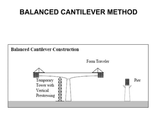
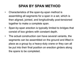
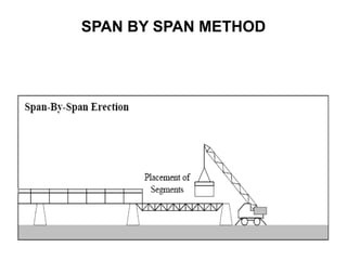
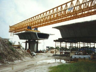
BRIDGE
LAUNCHING TECHNIQUES
• Two types of bridge construction:
– Pre-cast concrete segmental construction
– In-situ concrete segmental construction
• There are three launching techniques for bridge:
construction:
– Balanced cantilever method
– Span by span method
– Progressive placement method
TYPES
BALANCED CANTILEVER METHOD
• Balanced cantilever construction consists of building a
bridge superstructure from both sides of the pier table in
a scales-like fashion.
• The pier table element, serving as a base from which
cantilevering is begun, is usually between 6 and 12 m
long.
• To balance the weight of both arms of superstructure -
cantilever, the segments will be equally placed at both
ends.
BALANCED CANTILEVER METHOD
• Actual placement of new segments will hardly proceed
exactly at the same times. Therefore the pier can
undergo overturning bending moments and needs to be
designed accordingly. Temporary towers with vertical
pre-stressing or counterweights can provide additional
support.
• Balanced cantilevering can be carried out with cast-in-
place or pre-cast segments. For cast-inplace balanced
cantilevering a set of two form travelers is required, one
for each arm of the cantilever.
BALANCED CANTILEVER METHOD
• For multi-span bridges the form travelers can be
dismantled after finishing cantilevering from one pier
and can be set up for new use on the next pier.
• In case of a bridge with variable box girder depth the
pier table segment will be the most massive segment of
the superstructure. This segment needs to be
constructed prior to cantilevering to provide a working
platform from which the two form travelers can start.
The pier table segment will take a considerable amount
of time to construct, put into place either as large
precast segments or as cast-in-place with formwork
BALANCED CANTILEVER METHOD
SPAN BY SPAN METHOD
• Characteristics of the span-by-span method is
assembling all segments for a span in a set, which is
then aligned, jointed, and longitudinally post-tensioned
together to make a complete span.
• Span-by-span erection is typically limited to bridges that
consist of box girders with constant depth.
• The actual construction can have several variants, the
segments can be assembled on the ground and lifted in
place as a group by a heavy-duty crane or they can all
be put into their final position on erection girders along
the spans to be completed.
SPAN BY SPAN METHOD
SPAN BY SPAN METHOD
• Erection girders were supported at their ends by steel
falsework resting on the footings at each pier. After
completion of a span the erection girders were set forward
to the next span and adjusted.
• Fine adjustments of the segments on the erection girders
were possible by means of variable individual supports.
Finally, post-tensioning would be performed to link all the
segments together to form a complete span. With the
method described, an erection speed of one span per
about 3.5 days could be achieved.
• Erection girder need not rest on the ground, but can also
be supported by already existing substructure or
superstructure, e.g. piers of a span to be constructed.
• Project specific design of substructure and superstructure
and considerations as e.g. for traffic clearances set the
boundaries for erection with erection girders.
SPAN BY SPAN METHOD
PROGRESSIVE PLACEMENT METHOD
• The progressive placement method, in comparison with the
balanced cantilevering method, is a one-directional process.
• All cantilever segments are subsequently placed at the tip of
a cantilever that is built across all spans.
• Both cast-in-place and precast construction can be used.
• Often stay cables from the tip of a temporary tower on the
superstructure support the cantilever. With growing
cantilever superstructure this support mechanism has to be
advanced. Another method of support is use of temporary
towers.
• This method is competitive for spans between 30 to 50 m in
length, whereas incremental launching and balanced
cantilevering are used for much longer spans.
PROGRESSIVE PLACEMENT METHOD
• First of all, the placement process does not have to
switch sides as it occurs in the balanced cantilevering
method. Thus process control is simplified.
• In addition to this, good access to the placement
location is given on the already completed part of the
bridge superstructure.
• With the progressive placement method horizontal
curves can easily be accommodated.
ADVANTAGES
• From a structural point of view the progressive
placement method is advantageous in substructure
design. Only vertical forces from the dead load of the
superstructure under construction are experienced.
• In comparison with incremental launching and balanced
cantilevering, a simpler flow of forces takes place
between superstructure and the piers. No horizontal
forces are introduced in the piers and no unbalanced
bending moments have to be withstood by the piers. It
is therefore possible to immediately install the
permanent bearings.
ADVANTAGES
• As construction only progresses at the tip of one
cantilever, progress is slower than in balanced
cantilevering.
• Progressive placement resembles incremental
launching in that the superstructure undergoes stresses
very different from the permanent service conditions,
including even stress reversals. In both cases the
structure needs to incorporate temporary prestressing
tendons to account for these stresses.
• There is difficulty in erecting the first span with
progressive placement. Other construction methods
may have to be employed for this stage.
DISADVANTAGES
2.7 BRIDGE LAUNCHING.ppt

2.7 BRIDGE LAUNCHING.ppt

  • 1.
  • 2.
    • Two typesof bridge construction: – Pre-cast concrete segmental construction – In-situ concrete segmental construction • There are three launching techniques for bridge: construction: – Balanced cantilever method – Span by span method – Progressive placement method TYPES
  • 3.
    BALANCED CANTILEVER METHOD •Balanced cantilever construction consists of building a bridge superstructure from both sides of the pier table in a scales-like fashion. • The pier table element, serving as a base from which cantilevering is begun, is usually between 6 and 12 m long. • To balance the weight of both arms of superstructure - cantilever, the segments will be equally placed at both ends.
  • 4.
  • 5.
    • Actual placementof new segments will hardly proceed exactly at the same times. Therefore the pier can undergo overturning bending moments and needs to be designed accordingly. Temporary towers with vertical pre-stressing or counterweights can provide additional support. • Balanced cantilevering can be carried out with cast-in- place or pre-cast segments. For cast-inplace balanced cantilevering a set of two form travelers is required, one for each arm of the cantilever. BALANCED CANTILEVER METHOD
  • 6.
    • For multi-spanbridges the form travelers can be dismantled after finishing cantilevering from one pier and can be set up for new use on the next pier. • In case of a bridge with variable box girder depth the pier table segment will be the most massive segment of the superstructure. This segment needs to be constructed prior to cantilevering to provide a working platform from which the two form travelers can start. The pier table segment will take a considerable amount of time to construct, put into place either as large precast segments or as cast-in-place with formwork BALANCED CANTILEVER METHOD
  • 7.
    SPAN BY SPANMETHOD • Characteristics of the span-by-span method is assembling all segments for a span in a set, which is then aligned, jointed, and longitudinally post-tensioned together to make a complete span. • Span-by-span erection is typically limited to bridges that consist of box girders with constant depth. • The actual construction can have several variants, the segments can be assembled on the ground and lifted in place as a group by a heavy-duty crane or they can all be put into their final position on erection girders along the spans to be completed.
  • 8.
  • 9.
  • 10.
    • Erection girderswere supported at their ends by steel falsework resting on the footings at each pier. After completion of a span the erection girders were set forward to the next span and adjusted. • Fine adjustments of the segments on the erection girders were possible by means of variable individual supports. Finally, post-tensioning would be performed to link all the segments together to form a complete span. With the method described, an erection speed of one span per about 3.5 days could be achieved. • Erection girder need not rest on the ground, but can also be supported by already existing substructure or superstructure, e.g. piers of a span to be constructed. • Project specific design of substructure and superstructure and considerations as e.g. for traffic clearances set the boundaries for erection with erection girders. SPAN BY SPAN METHOD
  • 11.
    PROGRESSIVE PLACEMENT METHOD •The progressive placement method, in comparison with the balanced cantilevering method, is a one-directional process. • All cantilever segments are subsequently placed at the tip of a cantilever that is built across all spans. • Both cast-in-place and precast construction can be used. • Often stay cables from the tip of a temporary tower on the superstructure support the cantilever. With growing cantilever superstructure this support mechanism has to be advanced. Another method of support is use of temporary towers. • This method is competitive for spans between 30 to 50 m in length, whereas incremental launching and balanced cantilevering are used for much longer spans.
  • 12.
  • 13.
    • First ofall, the placement process does not have to switch sides as it occurs in the balanced cantilevering method. Thus process control is simplified. • In addition to this, good access to the placement location is given on the already completed part of the bridge superstructure. • With the progressive placement method horizontal curves can easily be accommodated. ADVANTAGES
  • 16.
    • From astructural point of view the progressive placement method is advantageous in substructure design. Only vertical forces from the dead load of the superstructure under construction are experienced. • In comparison with incremental launching and balanced cantilevering, a simpler flow of forces takes place between superstructure and the piers. No horizontal forces are introduced in the piers and no unbalanced bending moments have to be withstood by the piers. It is therefore possible to immediately install the permanent bearings. ADVANTAGES
  • 17.
    • As constructiononly progresses at the tip of one cantilever, progress is slower than in balanced cantilevering. • Progressive placement resembles incremental launching in that the superstructure undergoes stresses very different from the permanent service conditions, including even stress reversals. In both cases the structure needs to incorporate temporary prestressing tendons to account for these stresses. • There is difficulty in erecting the first span with progressive placement. Other construction methods may have to be employed for this stage. DISADVANTAGES