Download as PDF, PPTX
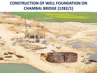

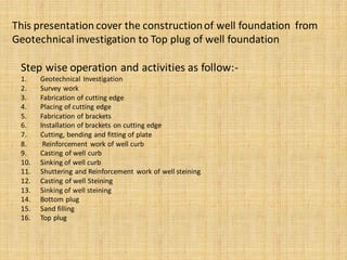
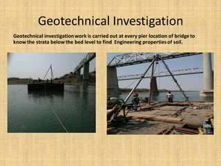
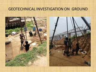

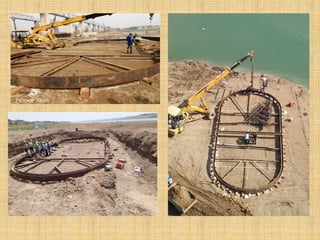
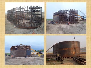
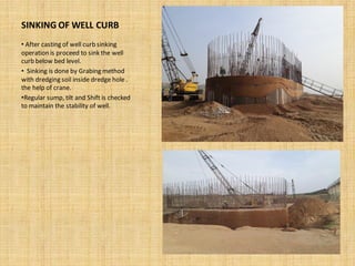
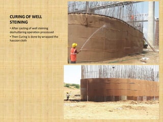
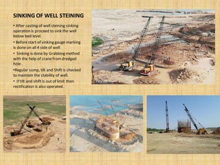
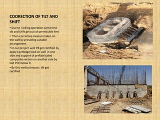
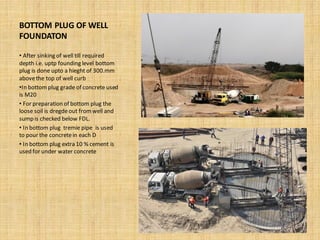
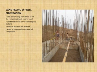
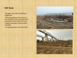


This presentation outlines the 16 step process for constructing a well foundation on a bridge, from geotechnical investigation to the top plug. The key steps include: 1) Conducting a geotechnical investigation to understand soil conditions. 2) Surveying and laying out the well locations. 3) Fabricating and installing the cutting edge and brackets that will form the base of the well. 4) Reinforcing and casting the well curb section below ground. 5) Sinking the well curb using a grabbing method. 6) Constructing and sinking the reinforced well steining section. 7) Pouring the bottom and top plug concrete sections to complete the well foundation.


