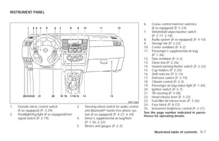
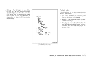
Download as PDF, PPTX


![Suggested upshift speeds
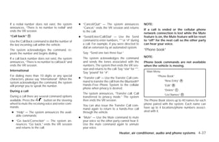
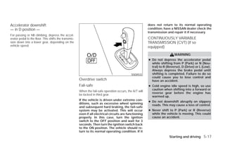
The following are suggested vehicle speeds for
shifting into a higher gear. These suggestions
relate to fuel economy and vehicle performance.
Actual upshift speeds will vary according to road
conditions, the weather and individual driving
habits.
For normal acceleration in low altitude areas (less
than 4,000 ft [1219 m]):
GEAR CHANGE MPH (km/h)
HR16DE MR18DE
1st to 2nd 15 (24) 8 (13)
SSD0535 SSD0552
2nd to 3rd 25 (40) 17 (27)
5 - speed 6 - speed
3rd to 4th 40 (64) 25 (40)
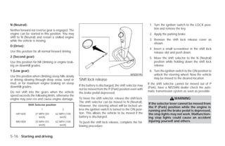
Shifting On the 5-speed manual transmission, you cannot
shift directly from 5th gear into R (Reverse). First 4th to 5th 45 (72) 36 (58)
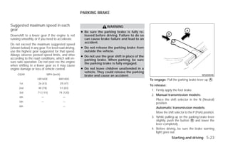
To change gears, or when upshifting or down- shift into N (Neutral), then into R (Reverse). 5th to 6th — 51(82)
shifting, depress the clutch pedal fully, shift into
On the 6–speed manual transmission to back up, For quick acceleration in low altitude areas and
the appropriate gear, then release the clutch lift up on the shift lever ring ᭺ and then move it to
1 high altitude areas (over 4,000 ft [1219 m]):
slowly and smoothly. the R (Reverse) position after stopping the ve-
Gear change MPH (km/h)
To ensure smooth gear changes, fully depress hicle completely.
the clutch pedal before operating the shift lever. If HR16DE MR18DE
The shift lever ring returns to its original position
the clutch pedal is not fully depressed before the when the shift lever is moved to the N (Neutral) 1st to 2nd 15 (24) 15 (24)
transmission is shifted, a gear noise may be position. 2nd to 3rd 25 (40) 25 (40)
heard. Transmission damage could occur.
If it is difficult to move the shift lever into R 3rd to 4th 40 (64) 40 (64)
Start the vehicle in 1st gear and shift to 2nd, 3rd, (Reverse) or 1 (1st), shift into N (Neutral), then 4th to 5th 45 (72) 45 (72)
4th up to 5th or 6th gear in sequence according release the clutch pedal. Depress the clutch
to vehicle speed. pedal again and shift into R (Reverse) or 1 (1st). 5th to 6th — 51 (82)
5-22 Starting and driving
੬ REVIEW COPY—2009 Versa (vrs)
Owners Manual—USA_English (nna)
09/10/08—debbie ੭](https://image.slidesharecdn.com/2009-versa-120818113428-phpapp02/85/2009-VERSA-OWNER-S-MANUAL-203-320.jpg)
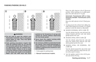
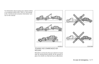
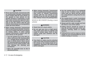
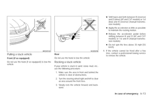

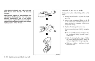
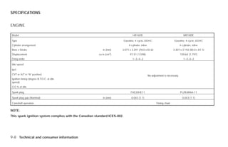


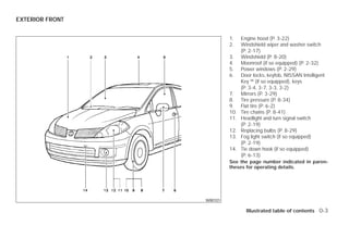
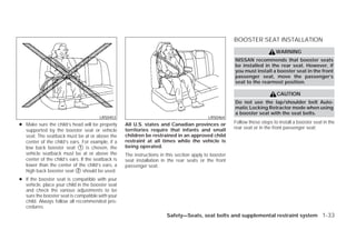
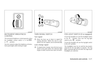
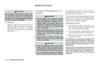
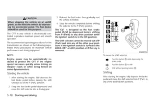
The document is the owner's manual for a Nissan Versa vehicle, providing detailed information on the operation and maintenance of the vehicle to ensure safe driving and compliance with regulations. It stresses the importance of reading the manual before driving, understanding safety features, and adhering to driving rules to prevent accidents. Included are warnings regarding modifications that may affect performance, safety, and warranty coverage.


![Carbene%20ppts%20(1)@[1].pptx](https://cdn.slidesharecdn.com/ss_thumbnails/carbene20ppts2011-230606145935-4ad73ba2-thumbnail.jpg?width=640&height=640&fit=bounds)


