Download as PDF, PPTX

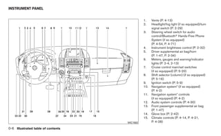
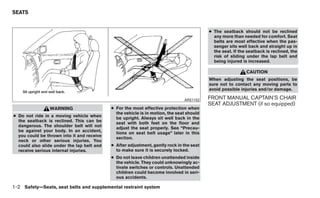
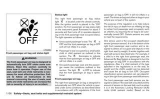

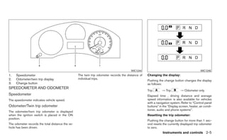
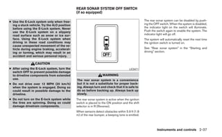
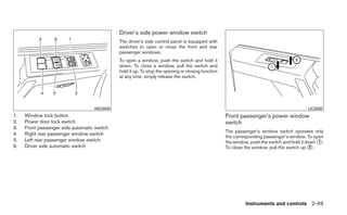

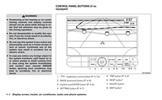
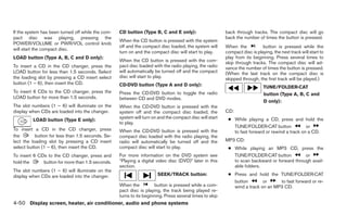
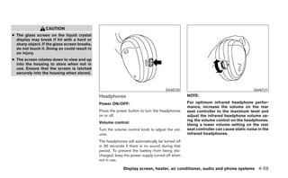
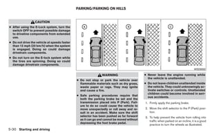
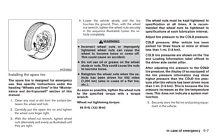
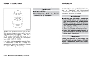
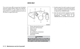
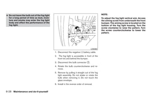
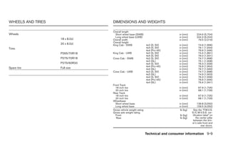
![CAUTION
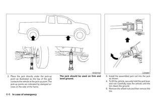
● The glass screen on the liquid crystal
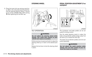
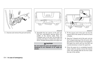
display may break if hit with a hard or
sharp object. If the glass breaks, do not
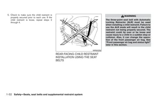
touch the liquid crystalline material,
which contains a small amount of mer-
cury. In case of contact with skin, wash
immediately with soap and water.
● Use a damp, soft cloth when cleaning
the Mobile Entertainment System com-
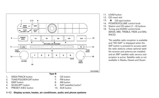
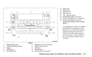
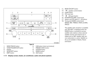
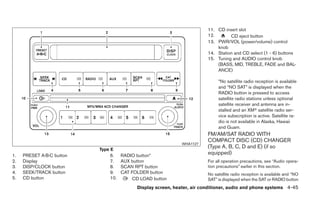
ponents. Do not use solvents or clean-
ing solutions.
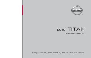
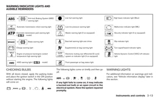
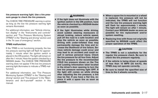
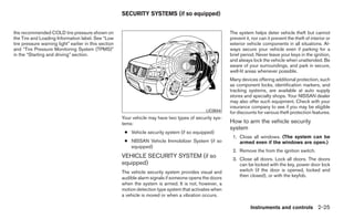
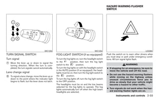
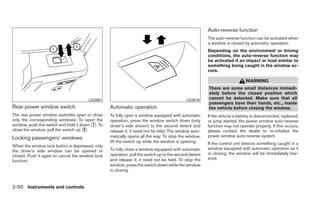
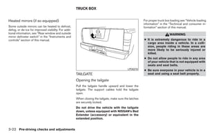
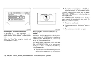
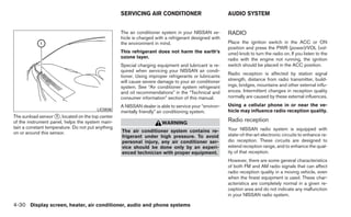
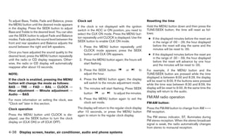
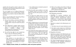
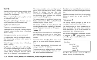
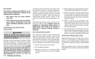
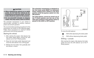
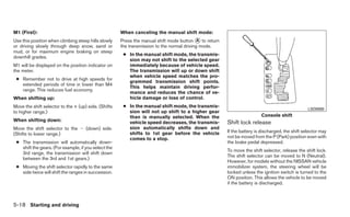
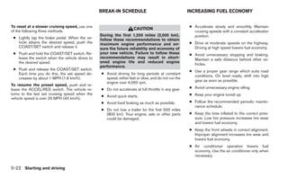
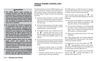
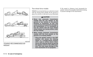
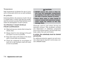
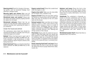
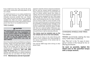
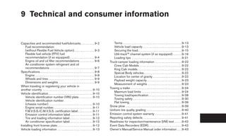
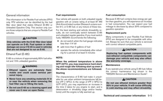
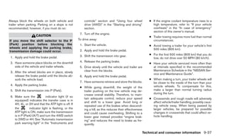
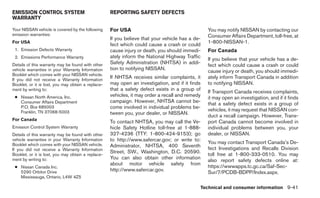
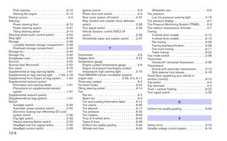
Do not attempt to use the system in extreme LHA0316
temperature conditions [below -4°F (-20°C) or
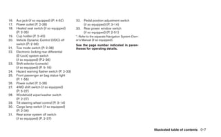
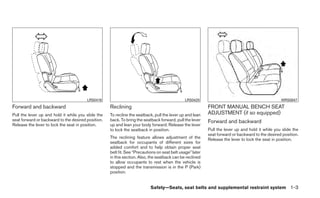
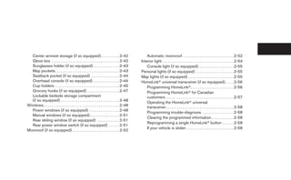
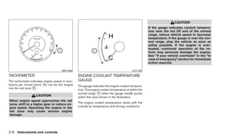
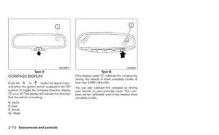
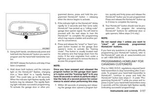
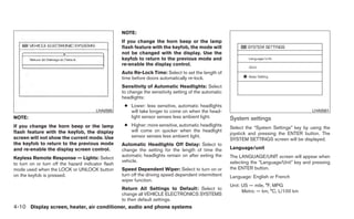
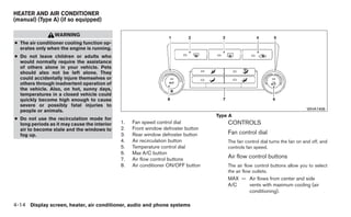
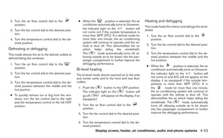
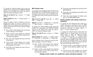
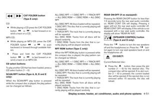
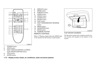
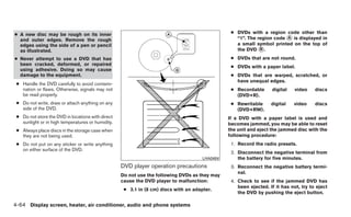
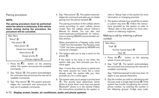
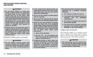
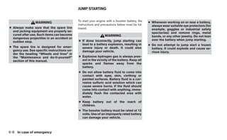
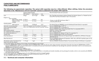
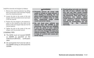
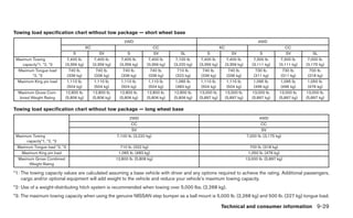
1. EJECT button DIGITAL VIDEO DISC (DVD) PLAYER
above 158°F (70°C)].
2. DVD slot CONTROLS
To avoid discharging the vehicle battery, do not 3. ENTER button
operate the system more than 15 minutes without Refer to “Playing a digital video disc (DVD)” later
4. POWER on/off button
starting the engine. in this section for the function of each button.
5. MODE button
6. Input jacks
7. STOP button
8. PLAY/PAUSE button
9. MENU button
10. DISPLAY button
11. NAVIGATION keys
Display screen, heater, air conditioner, audio and phone systems 4-57](https://image.slidesharecdn.com/2012-titan-120818114233-phpapp01/85/2012-TITAN-OWNER-S-MANUAL-227-320.jpg)
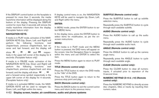
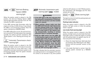
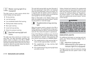
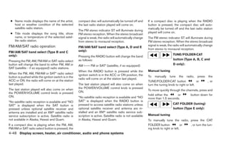
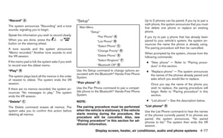
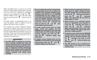
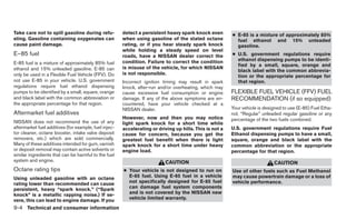
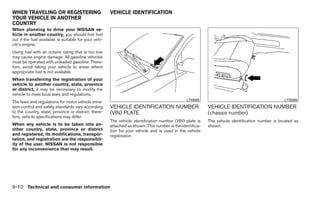
![Use the “≥10” button to input numbers greater To view the compatible device connected to the
than or equal to 10. Up to three digits can be AUX jacks, press the MODE button. For more
inputted when selecting the chapter/title/track information, see “Mode select button” earlier in
number. this section.
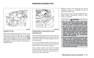
The subsequent actuation of numeric buttons will CARE AND MAINTENANCE
continuously shift the previously input number to
the “left”. Use a lightly dampened, lint free cloth to clean the
surfaces of your NISSAN Mobile Entertainment
The chapter/title/track number will be automati- System (DVD player face, screen, remote control,
cally selected (if valid, based on media content) if etc.).
3 seconds expire without any keypad inputs.
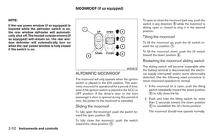
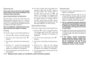
Do not attempt to use the system in extreme
The operator can cancel the input temperature conditions [below -4°F (-20°C) or
chapter/title/track number by actuating the above 158°F (70°C)].
CLEAR control prior to the expiration of the
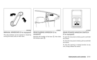
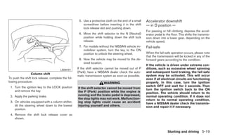
Do not attempt to operate the system in extreme LHA0049
3-second timer.
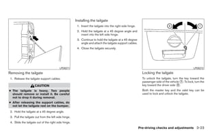
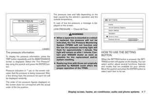
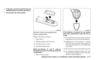
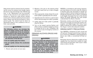
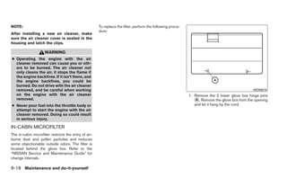
humidity conditions (less than 10% or more than HOW TO HANDLE THE DVD
These functions can be used only for the DVD 75%).
discs which correspond to them.
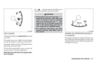
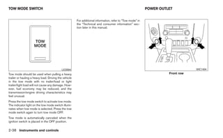
CAUTION
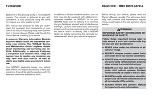
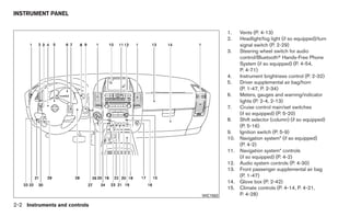
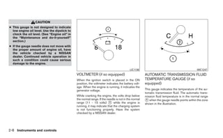
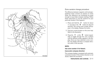
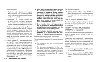
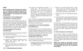
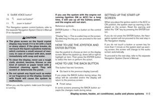
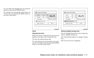
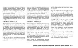
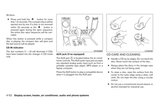
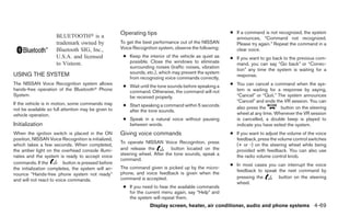
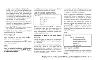
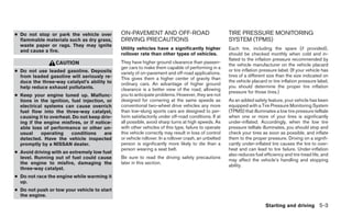
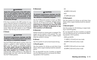
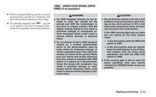
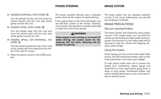
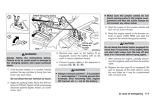
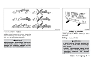
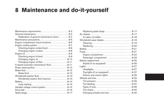
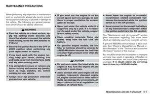
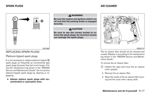
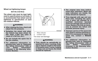
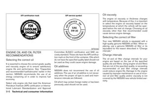
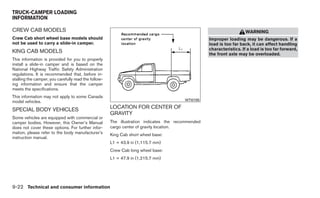
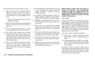
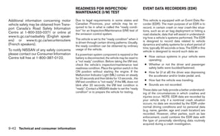
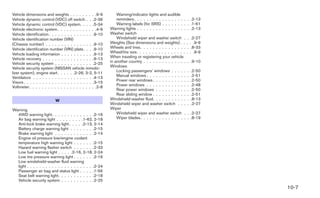
Auxiliary input jacks CAUTION
● Handle a DVD by its edges. Never touch
● Do not use any solvents or cleaning the surface of the disc.
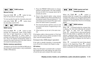
The auxiliary input jacks are located on the control
solutions when cleaning the video
panel. Compatible devices such as video games, ● To clean a disc, wipe the surface from
system.
camcorders and portable video players can be the center to the outer edge using a
connected to the auxiliary jacks. ● Do not use excessive force on the moni- clean, soft cloth. Do not wipe the disc
tor screen. using a circular motion.
The auxiliary jacks are color coded for identifica-
tion purposes. ● Avoid touching or scratching the moni- ● Do not use a conventional record
tor screen as it may become dirty or
● Yellow - video input damaged.
cleaner, benzine, thinner or alcohol in-
tended for industrial use.
● White - left channel audio input
● Red - right channel audio input
Display screen, heater, air conditioner, audio and phone systems 4-63](https://image.slidesharecdn.com/2012-titan-120818114233-phpapp01/85/2012-TITAN-OWNER-S-MANUAL-233-320.jpg)

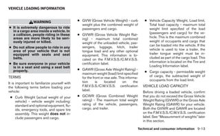


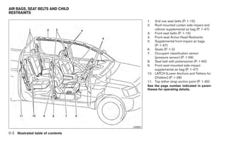
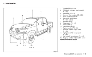
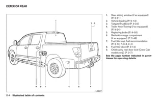
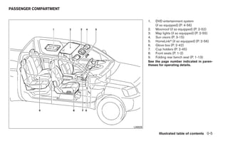
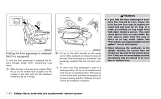
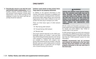
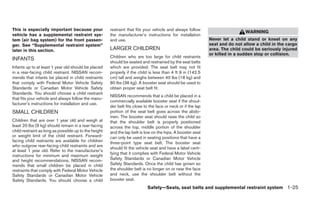
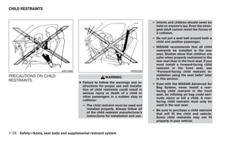
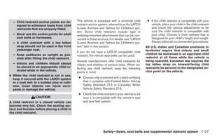
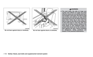
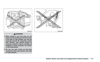
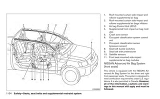
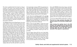
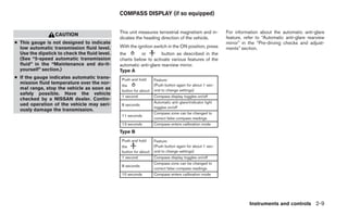
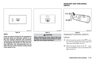
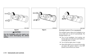
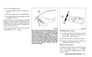
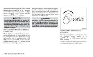
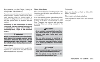
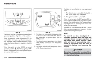
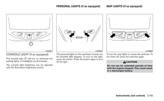
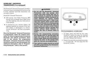
The 2012 Nissan Titan owner's manual provides essential safety and operational information for the vehicle, emphasizing the importance of reading the manual before driving. It includes guidelines for maintaining safety, using vehicle features, and understanding vehicle specifications. Additionally, the manual outlines customer care options and the contents necessary for vehicle operation and maintenance.


