Download as PDF, PPTX

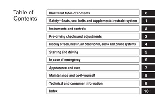

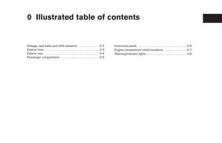
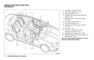
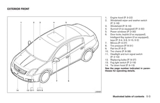
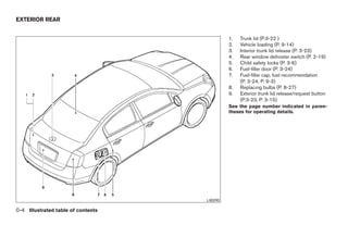
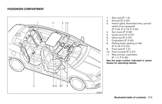
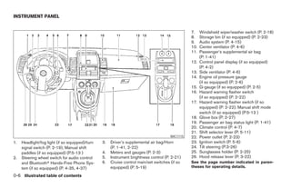
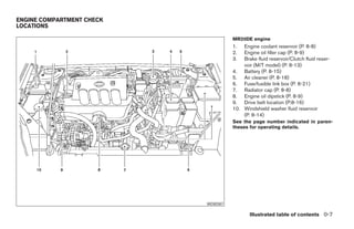
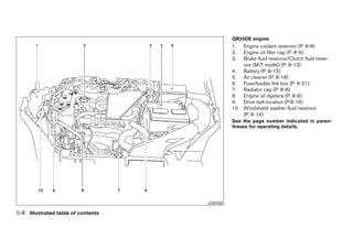
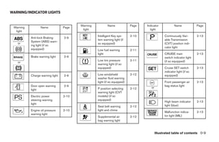
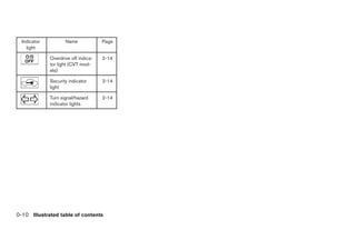

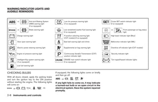

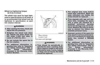


This owner's manual document contains important safety, operation, and maintenance information for a Nissan vehicle. It begins with a foreword emphasizing the importance of reading the manual before driving. The first section provides an illustrated guide to safety features like airbags and seat belts. Following sections outline exterior features, the instrument panel, the engine compartment, and warning lights. In summary, the document is an owner's manual that outlines key vehicle information to ensure safe and proper operation.