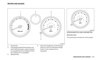
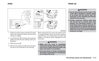
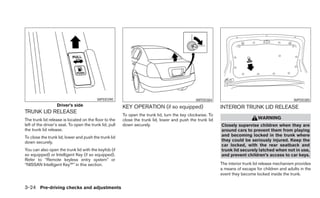
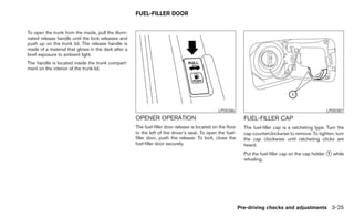
2010       SENTRA
                                  OWNER'S MANUAL


For your safety, read carefully and keep in this vehicle.
FOREWORD                                              READ FIRST—THEN DRIVE SAFELY


Welcome to the growing family of new NISSAN           Before driving your vehicle, please read this        MODIFICATION OF YOUR VEHICLE
owners. This vehicle is delivered to you with         Owner’s Manual carefully. This will ensure famil-
confidence. It was produced using the latest          iarity with controls and maintenance require-        This vehicle should not be modified.
techniques and strict quality control.                ments, assisting you in the safe operation of your   Modification      could      affect  its
                                                      vehicle.                                             performance, safety or durability, and
This manual was prepared to help you under-
                                                                                                           may     even     violate    governmental
stand the operation and maintenance of your
                                                                          WARNING                          regulations. In addition, damage or per-
vehicle so that you may enjoy many miles (kilome-
ters) of driving pleasure. Please read through this   IMPORTANT SAFETY INFORMATION RE-                     formance problems resulting from modi-
manual before operating your vehicle.                 MINDERS FOR SAFETY!                                  fications may not be covered under
                                                                                                           NISSAN warranties.
A separate Warranty Information Booklet               Follow these important driving rules to
explains details about the warranties cov-            help ensure a safe and comfortable trip
ering your vehicle. The “NISSAN Service               for you and your passengers!
and Maintenance Guide” explains details               ● NEVER drive under the influence of al-
about maintaining and servicing your ve-                cohol or drugs.
hicle. Additionally, a separate Customer
Care/Lemon Law Booklet (U.S. only) will               ● ALWAYS observe posted speed limits
explain how to resolve any concerns you                 and never drive too fast for conditions.
may have with your vehicle, as well as                ● ALWAYS give your full attention to driving
clarify your rights under your state’s lemon            and avoid using vehicle features or taking
law.                                                    other actions that could distract you.
Your NISSAN dealership knows your vehicle             ● ALWAYS use your seat belts and appro-
best. When you require any service or have any          priate child restraint systems. Preteen
questions, they will be glad to assist you with the     children should be seated in the rear seat.
extensive resources available to them.
                                                      ● ALWAYS provide information about the
                                                        proper use of vehicle safety features to
                                                        all occupants of the vehicle.
                                                      ● ALWAYS review this Owner’s Manual
                                                        for important safety information.
WHEN READING THE MANUAL


This manual includes information for all options                                                              CALIFORNIA PROPOSITION 65
available on this model. Therefore, you may find                                                              WARNING
some information that does not apply to your
vehicle.
                                                                                                                                WARNING
All information, specifications and illustrations in
                                                                                                              Engine exhaust, some of its constituents,
this manual are those in effect at the time of
                                                                                                              and certain vehicle components contain
printing. NISSAN reserves the right to change
                                                                                                              or emit chemicals known to the State of
specifications or design without notice and with-
                                                                                                              California to cause cancer and birth de-
out obligation.
                                                                                                              fects or other reproductive harm. In addi-
IMPORTANT INFORMATION ABOUT                                                                                   tion, certain fluids contained in vehicles
THIS MANUAL                                                                                                   and certain products of component wear
                                                                                                              contain or emit chemicals known to the
You will see various symbols in this manual. They                                                             State of California to cause cancer and
are used in the following ways:                                                                  APD1005      birth defects or other reproductive harm.
                                                       If you see this symbol, it means “Do not do this”      CALIFORNIA PERCHLORATE
                     WARNING                           or “Do not let this happen.”
This is used to indicate the presence of a                                                                    ADVISORY
hazard that could cause death or serious                                                                      Some vehicle parts, such as lithium batter-
personal injury. To avoid or reduce the                If you see a symbol similar to these in an illustra-   ies, may contain perchlorate material. The
risk, the procedures must be followed                  tion, it means the arrow points to the front of the
                                                                                                              following advisory is provided: “Perchlorate
precisely.                                             vehicle.
                                                                                                              Material – special handling may apply, See
                                                                                                              www.dtsc.ca.gov/hazardouswaste/perchlorate.”
                      CAUTION
                                                       Arrows in an illustration that are similar to these
This is used to indicate the presence of a
                                                       indicate movement or action.
hazard that could cause minor or moder-
ate personal injury or damage to your ve-
hicle. To avoid or reduce the risk, the pro-
cedures must be followed carefully.                    Arrows in an illustration that are similar to these
                                                       call attention to an item in the illustration.
BLUETOOTH௡ is a
                    trademark owned by
                    Bluetooth SIG, Inc.,
                    U.S.A. and licensed to
                    Visteon.

                    XM Radio௡ requires
                    subscription, sold
                    separately after first 90
                    days. Not available in
                    Alaska, Hawaii or
                    Guam. For more
                    information, visit
                    www.xmradio.com.


© Nissan Mexicana, S. A. de C. V.
All rights reserved. No part of this Owner’s
Manual may be reproduced or stored in a retrieval
system, or transmitted in any form, or by any
means, electronic, mechanical, photocopying,
recording or otherwise, without the prior written
permission of Nissan Mexicana, S. A. de C. V.
NISSAN CUSTOMER CARE PROGRAM
NISSAN CARES . . .
Both NISSAN and your NISSAN dealer are dedicated to serving all your automotive needs. Your satisfaction with your vehicle and your NISSAN dealer are
our primary concerns. Your NISSAN dealer is always available to assist you with all your automobile sales and service needs.
However, if there is something that your NISSAN      The Consumer Affairs Department will ask for the   You can write to NISSAN with the information at:
dealer cannot assist you with or you would like to   following information:
                                                                                                        For U.S. customers
provide NISSAN directly with comments or             – Your name, address, and telephone number          Nissan North America, Inc.
questions, please contact the NISSAN Con-
                                                     – Vehicle identification number (attached to the    Consumer Affairs Department
sumer Affairs Department using our toll-free
                                                       top of the instrument panel on the driver’s       P.O. Box 685003
number:
                                                       side)                                             Franklin, TN 37068-5003
For U.S. customers
                                                     – Date of purchase                                 For Canadian customers
 1-800-NISSAN-1
                                                                                                         Nissan Canada Inc.
 (1-800-647-7261)                                    – Current odometer reading                          5290 Orbitor Drive
For Canadian customers                               – Your NISSAN dealer’s name                         Mississauga, Ontario L4W 4Z5
 1-800-387-0122
                                                     – Your comments or questions
                                                     OR


                               We appreciate your interest in NISSAN and thank you for buying a quality NISSAN vehicle.
Table of   Illustrated table of contents                                      0
Contents   Safety—Seats, seat belts and supplemental restraint system         1
           Instruments and controls                                           2
           Pre-driving checks and adjustments                                 3
           Display screen, heater, air conditioner, audio and phone systems   4
           Starting and driving                                               5
           In case of emergency                                               6
           Appearance and care                                                7
           Maintenance and do-it-yourself                                     8
           Technical and consumer information                                 9
           Index                                                              10
0 Illustrated table of contents


Air bags, seat belts and child restraints . . . . . . . . . . . . . . 0-2                        Instrument panel. . . . . . . . . . . . . . . . . . . . . . . . . . . . . . . . . . . 0-6
Exterior front . . . . . . . . . . . . . . . . . . . . . . . . . . . . . . . . . . . . . . 0-3   Engine compartment check locations . . . . . . . . . . . . . . . . 0-7
Exterior rear. . . . . . . . . . . . . . . . . . . . . . . . . . . . . . . . . . . . . . . 0-4   Warning/indicator lights . . . . . . . . . . . . . . . . . . . . . . . . . . . . 0-9
Passenger compartment . . . . . . . . . . . . . . . . . . . . . . . . . . . 0-5
AIR BAGS, SEAT BELTS AND CHILD
RESTRAINTS

                                               1.   Top tether anchor (P. 1-28)
                                               2.   Rear headrest (P. 1-5)
                                               3.   Rear seat belts (P. 1-13)
                                               4.   Roof-mounted curtain side-impact
                                                    supplemental air bag (P. 1-42)
                                               5.   Front seat-mounted side-impact
                                                    supplemental air bag (P. 1-42)
                                               6.   Front-seat Active Head Restraint
                                                    (P. 1-10)
                                               7.   Front seat belts (P. 1-13)
                                               8.   Supplemental front-impact air bags
                                                    (P. 1-42)
                                               9.   Seats (P. 1-2)
                                              10.   Occupant classification sensor
                                                    (pressure sensor) (P.1-42)
                                              11.   Seat belt with pretensioner (P. 1-56)
                                              12.   LATCH (Lower Anchors and Tethers for
                                                    CHildren) (P. 1-26)
                                              See the page number indicated in paren-
                                              theses for operating details.


                                    LII0088

0-2 Illustrated table of contents
EXTERIOR FRONT


                           1.    Engine hood (P. 3-23)
                           2.    Windshield wiper and washer switch
                                 (P. 2-19)
                           3.    Windshield (P. 8-19)
                           4.    Moonroof (if so equipped) (P. 2-36)
                           5.    Power windows (if so equipped)
                                 (P. 2-33)
                           6.    Door locks, keyfob (if so equipped),
                                 NISSAN Intelligent Key ™
                                 (if so equipped), keys
                                 (P. 3-4, 3-7, 3-11, 3-2)
                           7.    Mirrors (P. 3-28)
                           8.    Tire pressure (P. 8-30)
                           9.    Flat tire (P. 6-2)
                           10.   Tire chains (P. 8-37)
                           11.   Headlight and turn signal switch
                                 (P. 2-21)
                           12.   Replacing bulbs (P. 8-27)
                           13.   Fog light switch (if so equipped)
                                 (P. 2-21)
                           14.   Tie down hook (if so equipped)
                                 (P. 6-13)
                           See the page number indicated in paren-
                           theses for operating details.


                 LII0089

                                   Illustrated table of contents 0-3
EXTERIOR REAR


                                              1.  Trunk lid (P.3-23 )
                                              2.  Vehicle loading (P. 9-13)
                                              3.  Interior trunk lid release (P. 3-24)
                                              4.  Rear window defroster switch (P. 2-20)
                                              5.  Child safety locks (P. 3-7)
                                              6.  Fuel-filler door (P. 3-25)
                                              7.  Fuel-filler cap, fuel recommendation
                                                  (P. 3-25, P. 9-3)
                                              8. Replacing bulbs (P. 8-27)
                                              9. Rear tie down hook (if so equipped)
                                                  (P. 6-13)
                                              10. Exterior trunk lid release/request button
                                                  (P. 3-17, 3-24)
                                              11. Rear view camera (P. 4-2)
                                              See the page number indicated in paren-
                                              theses for operating details.


                                    LII0176

0-4 Illustrated table of contents
PASSENGER COMPARTMENT


                                  1.  Rear seat (P. 1-3)
                                  2.  Moonroof (if so equipped) (P. 2-36)
                                  3.  Interior lights, illuminated entry,
                                      moonroof switch (if so equipped)
                                      (P. 2-39, P. 2-21, P. 2-36)
                                  4. Sun visors (P. 3-27)
                                  5. Rearview mirror (P. 3-28)
                                  6. Glove box (P. 2-30)
                                  7. Cup holders (P. 2-29)
                                  8. Parking brake, parking on hills
                                      (P. 5-18, P. 5-22)
                                  9. Front seat (P. 1-2)
                                  10. Front console (P. 2-30)
                                  11. Rear armrest, cup holders
                                      (if so equipped) (P. 1-7, P 2-29)
                                  See the page number indicated in paren-
                                  theses for operating details.


                        LII0091

                                         Illustrated table of contents 0-5
INSTRUMENT PANEL


                                                                                                 7.    Windshield wiper/washer switch (P. 2-19)
                                                                                                 8.    Storage bin (if so equipped) (P. 2-27)
                                                                                                 9.    Audio system (P. 4-13)
                                                                                                 10.   Center ventilator (P. 4-4)
                                                                                                 11.   Passenger’s supplemental air bag
                                                                                                       (P. 1-42)
                                                                                                 12.   Side ventilator (P. 4-4)
                                                                                                 13.   Storage bin (if so equipped) (P. 2-27)
                                                                                                 14.   Engine oil pressure gauge
                                                                                                       (if so equipped) (P. 2-7)
                                                                                                 15.   g (gravity)-force gauge (if so equipped)
                                                                                                       (P. 2-5)
                                                                                                 16.   Hazard warning flasher switch
                                                                                                       (if so equipped) (P. 2-23)
                                                                                                 17.   Hazard warning flasher switch
                                                                                                       (if so equipped) (P. 2-23); Manual shift
                                                                                                       mode switch (if so equipped) (P.5-14)
                                                                                                 18.   Glove box (P. 2-30)
                                                                                                 19.   Front passenger air bag status light
                                                                                                       (P. 1-42)
                                                                                                 20.   Climate control (P. 4-4)
                                                                                                 21.   Shift selector (P. 5-11)
                                                                                                 22.   Power outlet (P. 2-26)
                                                                                       WIC1532   23.   Ignition switch (P. 5-7)
1.   Headlight/fog light (if so equipped) /turn   3.   Driver’s supplemental air bag/Horn        24.   Tilt steering (P.3-27)
     signal switch (P. 2-21); Manual shift             (P. 1-42, 2-24)                           25.   Storage bin (P. 2-27)
     paddles (if so equipped) (P.5-14)            4.   Meters and gauges (P. 2-3)                26.   Hood release lever (P. 3-23)
2.   Steering wheel switch for audio control      5.   Instrument brightness control (P. 2-22)   27.   Vehicle Dynamic Control (VDC) off
     and Bluetoothா Hands-Free Phone Sys-         6.   Cruise control main/set switches                switch (if so equipped) (P.2-15)
     tem (if so equipped) (P. 4-40, 4-42)              (if so equipped) (P. 5-19)                See the page number indicated in paren-
                                                                                                 theses for operating details.
0-6 Illustrated table of contents
ENGINE COMPARTMENT CHECK
LOCATIONS
                                     MR20DE engine
                                     1.  Engine coolant reservoir (P. 8-8)
                                     2.  Engine oil filler cap (P. 8-9)
                                     3.  Brake fluid reservoir/Clutch fluid
                                         reservoir (M/T model) (P. 8-13)
                                     4. Battery (P. 8-15)
                                     5. Air cleaner (P. 8-18)
                                     6. Fuse/fusible link box (P. 8-21)
                                     7. Radiator cap (P. 8-8)
                                     8. Engine oil dipstick (P. 8-9)
                                     9. Drive belt location (P.8-16)
                                     10. Window washer fluid reservoir (P. 8-14)
                                     See the page number indicated in paren-
                                     theses for operating details.


                           WDI0587

                                            Illustrated table of contents 0-7
QR25DE engine
                                              1.  Engine coolant reservoir (P. 8-8)
                                              2.  Engine oil filler cap (P. 8-9)
                                              3.  Brake fluid reservoir/Clutch fluid
                                                  reservoir (M/T model) (P. 8-13)
                                              4. Battery (P. 8-15)
                                              5. Air cleaner (P. 8-18)
                                              6. Fuse/fusible link box (P. 8-21)
                                              7. Radiator cap (P. 8-8)
                                              8. Engine oil dipstick (P. 8-9)
                                              9. Drive belt location (P.8-16)
                                              10. Window washer fluid reservoir (P. 8-14)
                                              *Engine cover removed for clarity.
                                              See the page number indicated in paren-
                                              theses for operating details.


                                    WDI0637

0-8 Illustrated table of contents
WARNING/INDICATOR LIGHTS


 Warning          Name            Page   Warning           Name             Page   Indicator             Name             Page
  light                                   light                                      light

           Anti-lock Braking      2-9              Low tire pressure        2-11                 Continuously Vari-       2-13
           System (ABS) warn-                      warning light (if so                          able Transmission
   or
           ing light (if so                        equipped)                                     (CVT) position indi-
           equipped)                                                                             cator light (CVT
                                                   Low windshield           2-12                 models)
           Brake warning light    2-9              washer fluid warning
                                                   light (if so equipped)                        Cruise main switch       2-13
   or                                                                                            indicator light (if so
                                                   NISSAN Intelligent       3-3                  equipped)
                                                   Key™ warning light
                                                   (if so equipped)                              Cruise set switch        2-13
           Charge warning light   2-10                                                           indicator light (if so
                                                   P position selecting     2-12                 equipped)
                                                   warning light (CVT
           Door open warning      2-10             models) (if so                                Front passenger air      2-13
           light                                   equipped)                                     bag status light
                                                                                      or
           Electric power         2-10             Seat belt warning        2-12
           steering warning                        light and chime
           light
                                                   Supplemental air         2-13                 High beam indicator      2-13
           Engine oil pressure    2-10             bag warning light                             light (blue)
           warning light
                                                                                                 Malfunction Indica-      2-14
           Low fuel warning       2-11                                                           tor Light (MIL)
           light


                                                                                           Illustrated table of contents 0-9
Indicator           Name               Page
    light

              Overdrive off indica-      2-14
              tor light (CVT mod-
              els)

              Security indicator         2-14
              light

              Side light and head-       2-15
              light indicator light
              (green)

              Slip indicator light (if   2-15
              so equipped)

              Turn signal/hazard         2-15
              indicator lights

              Vehicle Dynamic            2-15
              Control (VDC) OFF
              indicator light (if so
              equipped)


0-10 Illustrated table of contents
1 Safety—Seats, seat belts and
supplemental restraint system

Seats . . . . . . . . . . . . . . . . . . . . . . . . . . . . . . . . . . . . . . . . . . . . 1-2     Precautions on child restraints . . . . . . . . . . . . . . . . . . 1-24
   Front manual seat adjustment . . . . . . . . . . . . . . . . . . . . 1-2                           LATCH (Lower Anchors and Tethers for
   Rear folding seat system (if so equipped) . . . . . . . . . 1-3                                    CHildren) System . . . . . . . . . . . . . . . . . . . . . . . . . . . . . 1-26
   Head restraints. . . . . . . . . . . . . . . . . . . . . . . . . . . . . . . . . 1-7               Rear-facing child restraint installation using
   Adjustable headrest (if so equipped). . . . . . . . . . . . . 1-10                                 LATCH . . . . . . . . . . . . . . . . . . . . . . . . . . . . . . . . . . . . . . . 1-28
Seat belts . . . . . . . . . . . . . . . . . . . . . . . . . . . . . . . . . . . . . . . 1-13         Rear-facing child restraint installation using
   Precautions on seat belt usage. . . . . . . . . . . . . . . . . . 1-13                             the seat belts . . . . . . . . . . . . . . . . . . . . . . . . . . . . . . . . . 1-31
   Pregnant women . . . . . . . . . . . . . . . . . . . . . . . . . . . . . . 1-16                    Forward-facing child restraint installation
   Injured persons. . . . . . . . . . . . . . . . . . . . . . . . . . . . . . . . 1-16                using LATCH. . . . . . . . . . . . . . . . . . . . . . . . . . . . . . . . . . 1-33
   Three-point type seat belt with retractor . . . . . . . . . . 1-16                                 Forward-facing child restraint installation
   Shoulder belt height adjustment (front seats) . . . . . 1-21                                       using the seat belts . . . . . . . . . . . . . . . . . . . . . . . . . . . . 1-35
   Seat belt extenders . . . . . . . . . . . . . . . . . . . . . . . . . . . . 1-22                   Installing top tether strap . . . . . . . . . . . . . . . . . . . . . . . 1-39
   Seat belt maintenance . . . . . . . . . . . . . . . . . . . . . . . . . 1-22                       Booster seats . . . . . . . . . . . . . . . . . . . . . . . . . . . . . . . . . 1-39
Child safety . . . . . . . . . . . . . . . . . . . . . . . . . . . . . . . . . . . . . . 1-23       Supplemental restraint system . . . . . . . . . . . . . . . . . . . . . 1-42
   Infants. . . . . . . . . . . . . . . . . . . . . . . . . . . . . . . . . . . . . . . . 1-23        Precautions on supplemental restraint
   Small children . . . . . . . . . . . . . . . . . . . . . . . . . . . . . . . . . 1-23              system . . . . . . . . . . . . . . . . . . . . . . . . . . . . . . . . . . . . . . . 1-42
   Larger children . . . . . . . . . . . . . . . . . . . . . . . . . . . . . . . . 1-24               Supplemental air bag warning labels . . . . . . . . . . . . . 1-57
Child restraints . . . . . . . . . . . . . . . . . . . . . . . . . . . . . . . . . . . 1-24           Supplemental air bag warning light . . . . . . . . . . . . . . 1-57
SEATS


                                                                                          ● The seatback should not be reclined
                                                                                            any more than needed for comfort. Seat
                                                                                            belts are most effective when the pas-
                                                                                            senger sits well back and straight up in
                                                                                            the seat. If the seatback is reclined, the
                                                                                            risk of sliding under the lap belt and
                                                                                            being injured is increased.

                                                                                                            CAUTION
                                                                                          When adjusting the seat positions, be
                                                                                          sure not to contact any moving parts to
                                                                                          avoid possible injuries and/or damage.
                                                                                          FRONT MANUAL SEAT
                                                                               ARS1152
                                                                                          ADJUSTMENT
                WARNING                     ● For the most effective protection when
                                              the vehicle is in motion, the seat should
● Do not ride in a moving vehicle when        be upright. Always sit well back in the
  the seatback is reclined. This can be       seat with both feet on the floor and
  dangerous. The shoulder belt will not       adjust the seat properly. See “Precau-
  be against your body. In an accident,       tions on seat belt usage” later in this
  you could be thrown into it and receive     section.
  neck or other serious injuries. You
  could also slide under the lap belt and   ● After adjustment, gently rock in the seat
  receive serious internal injuries.          to make sure it is securely locked.
                                            ● Do not leave children unattended inside
                                              the vehicle. They could unknowingly ac-
                                              tivate switches or controls. Unattended
                                              children could become involved in seri-
                                              ous accidents.

1-2 Safety—Seats, seat belts and supplemental restraint system
WRS0719                                                WRS0720                                              WRS0721
Forward and backward                                  Reclining                                              Seat lifter (if so equipped for driver’s
Pull the center of the bar up and hold it while you   To recline the seatback, pull the lever up and lean    seat)
slide the seat forward or backward to the desired     back. To bring the seatback forward, pull the lever    Pull up or push down the adjusting lever to adjust
position. Release the bar to lock the seat in         up and lean your body forward. Release the lever       the seat height until the desired position is
position.                                             to lock the seatback in position.                      achieved.
                                                      The reclining feature allows adjustment of the         REAR FOLDING SEAT SYSTEM (if so
                                                      seatback for occupants of different sizes for
                                                      added comfort and to help obtain proper seat           equipped)
                                                      belt fit. See “Precautions on seat belt usage” later
                                                      in this section. Also, the seatback can be reclined
                                                      to allow occupants to rest when the vehicle is
                                                      stopped and the shift selector (CVT) is in P (Park)
                                                      or the manual transmission is in N (Neutral) with
                                                      the parking brake applied.

                                                                             Safety—Seats, seat belts and supplemental restraint system 1-3
● When returning the seatbacks to the
                                                                                                       upright position, be certain they are
                                                                                                       completely secured in the latched posi-
                                                                                                       tion. If they are not completely secured,
                                                                                                       passengers may be injured in an acci-
                                                                                                       dent or sudden stop.
                                                                                                     ● Closely supervise children when they
                                                                                                       are around cars to prevent them from
                                                                                                       playing and becoming locked in the
                                                                                                       trunk where they could be seriously in-
                                                                                                       jured. Keep the car locked, with the rear
                                                                                                       seatback and trunk lid securely latched
                                                                                                       when not in use, and prevent children’s
                                          LRS0728                                        WRS0726       access to car keys.

Interior trunk access (if so equipped)                                  WARNING
The trunk can be accessed from the rear seat for      ● Never allow anyone to ride in the cargo
loading and unloading, as shown.                        area or on the rear seat when it is in the
 1. Stow outboard seat belts with clip before           fold-down position. Use of these areas
    folding rear seatbacks.                             by passengers without proper restraints
                                                        could result in serious injury in an acci-
When folding the passenger’s side rear seat-            dent or sudden stop.
back, first disconnect and stow the center seat
                                                      ● Properly secure all cargo with ropes or
belt. See “Stowing the rear center seat belt” later
                                                        straps to help prevent it from sliding or
in this section.
                                                        shifting. Do not place cargo higher than
                                                        the seatbacks. In a sudden stop or col-
 2. Pull up on the strap ᭺ located on the top
                          A                             lision, unsecured cargo could cause
    outboard side of the seat to be folded.             personal injury.
 3. Fold seatback down.
1-4 Safety—Seats, seat belts and supplemental restraint system
WRS0827                    LRS0730                                             LRS0733
Folding the rear cushions and                                                2. Fold down the rear headrest. Pull the head-
seatbacks (if so equipped)                                                      rest forward and rotate until it clicks into the
                                                                                locked position ᭺.
                                                                                                 1
 1. Lift up on the front edge of the seat cushion
    and fold it toward the front of the vehicle.


                                                    Safety—Seats, seat belts and supplemental restraint system 1-5
● Properly secure all cargo with ropes or
                                                                                                      straps to help prevent it from sliding or
                                                                                                      shifting. Do not place cargo higher than
                                                                                                      the seatbacks. In a sudden stop or col-
                                                                                                      lision, unsecured cargo could cause
                                                                                                      personal injury.
                                                                                                    ● When returning the seatbacks to the
                                                                                                      upright position, be certain they are
                                                                                                      completely secured in the latched posi-
                                                                                                      tion. If they are not completely secured,
                                                                                                      passengers may be injured in an acci-
                                                                                                      dent or sudden stop.
                                                                                                    ● Closely supervise children when they
                                         LRS0734                                         LRS0731      are around cars to prevent them from
 3. To return the headrest to the normal position,   4. Fold down seatbacks. See “Interior trunk      playing and becoming locked in the
    push down ᭺ and release then rotate up
                    1                                   access” earlier in this section.              trunk where they could be seriously in-
    until in position ᭺.
                      2                                                                               jured. Keep the car locked, with the rear
                                                                       WARNING                        seatback and trunk lid securely latched
                                                                                                      when not in use, and prevent children’s
                                                     ● Never allow anyone to ride in the cargo        access to car keys.
                                                       area or on the rear seat when it is in the
                                                       fold-down position. Use of these areas
                                                       by passengers without proper restraints
                                                       could result in serious injury in an acci-
                                                       dent or sudden stop.


1-6 Safety—Seats, seat belts and supplemental restraint system
HEAD RESTRAINTS
                                                                       WARNING
                                                     Head restraints supplement the other ve-
                                                     hicle safety systems. They may provide
                                                     additional protection against injury in cer-
                                                     tain rear end collisions. Adjust the head
                                                     restraints properly, as specified in this
                                                     section. Check the adjustment after
                                                     someone else uses the seat. Do not attach
                                                     anything to the head restraint stalks or
                                                     remove the head restraint. Do not use the
                                                     seat if the head restraint has been re-
                                           WIC1097
                                                     moved. If the head restraint was removed,                                              LRS0893
                                                     reinstall and properly adjust the head re-
Center armrest (if so equipped)                      straint before an occupant uses the seat-      The illustration shows the seating positions
                                                     ing position. Failure to follow these in-      equipped with head restraints. All of the head
Pull the armrest down until it is horizontal.                                                       restraints are adjustable.
                                                     structions can reduce the effectiveness of
                                                     the head restraints. This may increase the     ᭡ Indicates the seating position is equipped with
                                                     risk of serious injury or death in a           a head restraint.
                                                     collision.


                                                                        Safety—Seats, seat belts and supplemental restraint system 1-7
LRS0887                                         WRS0134                                                 LRS0888
Components                               Adjustment                                         To raise the head restraint, pull it up.
 1. Head restraint                       Adjust the head restraint so the center is level
                                         with the center of the seat occupant’s ears.
 2. Adjustment notches
 3. Lock knob
 4. Stalks


1-8 Safety—Seats, seat belts and supplemental restraint system
LRS0889                                             LRS0890                                              LRS0891
To lower, push and hold the lock knob and push   Removal                                              Install
the head restraint down.
                                                 Use the following procedure to remove the ad-         1. Align the head restraint stalks with the holes
                                                 justable head restraints.                                in the seat. Make sure the head restraint is
                                                                                                          facing the correct direction. The stalk with
                                                  1. Pull the head restraint up to the highest
                                                                                                          the adjustment notches ᭺ must be installed
                                                                                                                                    1
                                                     position.
                                                                                                          in the hole with the lock button ᭺.
                                                                                                                                            2
                                                  2. Push and hold the lock knob.
                                                                                                       2. Push and hold the lock knob and push the
                                                  3. Remove the head restraint from the seat.             head restraint down.
                                                  4. Store the head restraint properly so it is not    3. Properly adjust the head restraint before an
                                                     loose in the vehicle.                                occupant uses the seating position.
                                                  5. Install and properly adjust the head restraint
                                                     before an occupant uses the seating posi-
                                                     tion.

                                                                       Safety—Seats, seat belts and supplemental restraint system 1-9
Adjust the Active Head Restraints properly as
                                                      described in this section.
                                                      ADJUSTABLE HEADREST (if so
                                                      equipped)
                                                                        WARNING
                                                      The adjustable headrests supplement the
                                                      other vehicle safety systems. They may
                                                      provide additional protection against in-
                                                      jury in certain rear end collisions. Adjust
                                                      the headrests properly, as specified in this
                                                      section. Check the adjustment after
                                                      someone else uses the seat. Do not attach
                                         SPA1025      anything to the adjustable headrest stalks                                              LRS0898

Front-seat Active Head Restraints                     or remove the adjustable headrests. Do          The illustration shows the seating positions
                                                      not use the seat if the adjustable head-        equipped with adjustable headrests. All of the
The Active Head Restraint moves forward utiliz-       rests have been removed. If the headrest        headrests are adjustable.
ing the force that the seatback receives from the     was removed, reinstall and properly adjust
occupant in a rear-end collision. The movement                                                        Ⅲ Indicates the seating position is equipped with
                                                      the headrest before an occupant uses the
of the head restraint helps support the occu-                                                         an adjustable headrest.
                                                      seating position. Failure to follow these
pant’s head by reducing its backward movement         instructions can reduce the effectiveness       + Indicates the seating position is not equipped
and helping absorb some of the forces that may        of the adjustable headrests. This may in-       with a head restraint or adjustable headrest.
lead to whiplash-type injuries.                       crease the risk of serious injury or death in
Active Head Restraints are effective for collisions   a collision.
at low to medium speeds in which it is said that
whiplash injury occurs most.
Active Head Restraints operate only in certain
rear-end collisions. After the collision, the head
restraints return to their original position.
1-10 Safety—Seats, seat belts and supplemental restraint system
LRS0887                                            WRS0134                                           LRS0888
Components                         Adjustment                                            To raise the headrest, pull it up.
1. Adjustable headrest             Adjust the headrest so the center is level with the
                                   center of the seat occupant’s ears.
2. Adjustment notches
3. Lock knob
4. Stalks


                                                        Safety—Seats, seat belts and supplemental restraint system 1-11
LRS0889                                             LRS0890                                             LRS0891
To lower, push and hold the lock knob and push   Removal                                              Install
the headrest down.
                                                 Use the following procedure to remove the ad-         1. Align the headrest stalks with the holes in
                                                 justable headrests.                                      the seat. Make sure the headrest is facing
                                                                                                          the correct direction. The stalk with the ad-
                                                  1. Pull the headrest up to the highest position.
                                                                                                          justment notches ᭺ must be installed in the
                                                                                                                             1
                                                  2. Push and hold the lock knob.                         hole with the lock button ᭺.
                                                                                                                                     2

                                                  3. Remove the headrest from the seat.                2. Push and hold the lock knob and push the
                                                                                                          headrest down.
                                                  4. Store the headrest properly so it is not loose
                                                     in the vehicle.                                   3. Properly adjust the headrest before an oc-
                                                                                                          cupant uses the seating position.
                                                  5. Install and properly adjust the headrest be-
                                                     fore an occupant uses the seating position.


1-12 Safety—Seats, seat belts and supplemental restraint system
SEAT BELTS


                                                                      SSS0136
PRECAUTIONS ON SEAT BELT
USAGE
If you are wearing your seat belt properly ad-
justed and you are sitting upright and well back in
your seat with both feet on the floor, your chances
of being injured or killed in an accident and/or the
severity of injury may be greatly reduced.
NISSAN strongly encourages you and all of your
passengers to buckle up every time you drive,
even if your seating position includes a supple-
mental air bag.
Most U.S. states and Canadian provinces
or territories specify that seat belts be worn
at all times when a vehicle is being driven.

                                                       Safety—Seats, seat belts and supplemental restraint system 1-13
SSS0134                                       SSS0016

                 WARNING                                                                      WARNING
● Every person who drives or rides in this                                  ● The seat belt should be properly ad-
  vehicle should use a seat belt at all                                       justed to a snug fit. Failure to do so may
  times. Children should be properly re-                                      reduce the effectiveness of the entire
  strained in the rear seat and, if appro-                                    restraint system and increase the
  priate, in a child restraint.                                               chance or severity of injury in an acci-
                                                                              dent. Serious injury or death can occur
                                                                              if the seat belt is not worn properly.


1-14 Safety—Seats, seat belts and supplemental restraint system
● Be sure the seat belt tongue is securely    ● Once a seat belt pretensioner has acti-
                                                fastened to the proper buckle.                vated, it cannot be reused and must be
                                                                                              replaced together with the retractor.
                                              ● Do not wear the seat belt inside out or
                                                                                              See your NISSAN dealer.
                                                twisted. Doing so may reduce its
                                                effectiveness.                              ● Removal and installation of preten-
                                                                                              sioner system components should be
                                              ● Do not allow more than one person to
                                                                                              done by a NISSAN dealer.
                                                use the same seat belt.
                                                                                            ● All seat belt assemblies, including re-
                                              ● Never carry more people in the vehicle
                                                                                              tractors and attaching hardware,
                                                than there are seat belts.
                                                                                              should be inspected after any collision
                                              ● If the seat belt warning light glows con-     by a NISSAN dealer. NISSAN recom-
                                                tinuously while the ignition is turned        mends that all seat belt assemblies in
                                                ON with all doors closed and all seat         use during a collision be replaced un-
                                   SSS0014      belts fastened, it may indicate a mal-        less the collision was minor and the
                                                function in the system. Have the system       belts show no damage and continue to
                 WARNING                        checked by a NISSAN dealer.                   operate properly. Seat belt assemblies
● Always route the shoulder belt over         ● No changes should be made to the seat         not in use during a collision should also
  your shoulder and across your chest.          belt system. For example, do not modify       be inspected and replaced if either
  Never put the belt behind your back,          the seat belt, add material, or install       damage or improper operation is noted.
  under your arm or across your neck. The       devices that may change the seat belt       ● All child restraints and attaching hard-
  belt should be away from your face and        routing or tension. Doing so may affect       ware should be inspected after any col-
  neck, but not falling off your shoulder.      the operation of the seat belt system.        lision. Always follow the restraint
● Position the lap belt as low and snug as      Modifying or tampering with the seat          manufacturer’s inspection instructions
  possible AROUND THE HIPS, NOT THE             belt system may result in serious per-        and replacement recommendations.
  WAIST. A lap belt worn too high could         sonal injury.                                 The child restraints should be replaced
  increase the risk of internal injuries in                                                   if they are damaged.
  an accident.


                                                               Safety—Seats, seat belts and supplemental restraint system 1-15
PREGNANT WOMEN                                       THREE-POINT TYPE SEAT BELT
NISSAN recommends that pregnant women use            WITH RETRACTOR
seat belts. The seat belt should be worn snug and
always position the lap belt as low as possible                       WARNING
around the hips, not the waist. Place the shoulder   ● Every person who drives or rides in this
belt over your shoulder and across your chest.         vehicle should use a seat belt at all
Never run the lap/shoulder belt over your ab-          times.
dominal area. Contact your doctor for specific
recommendations.                                     ● Do not ride in a moving vehicle when
                                                       the seatback is reclined. This can be
INJURED PERSONS                                        dangerous. The shoulder belt will not
                                                       be against your body. In an accident,
NISSAN recommends that injured persons use
                                                       you could be thrown into it and receive
seat belts. Check with your doctor for specific
                                                       neck or other serious injuries. You
recommendations.                                                                                                                         WRS0719
                                                       could also slide under the lap belt and
                                                       receive serious internal injuries.                   Manual front seat shown
                                                     ● For the most effective protection when      Fastening the seat belts
                                                       the vehicle is in motion, the seat should    1. Adjust the seat. See “Seats” earlier in this
                                                       be upright. Always sit well back in the         section.
                                                       seat with both feet on the floor and
                                                       adjust the seat belt properly.


1-16 Safety—Seats, seat belts and supplemental restraint system
The Emergency Locking Retractor (ELR) mode
                                                                                                         allows the seat belt to extend and retract to allow
                                                                                                         the driver and passengers some freedom of
                                                                                                         movement in the seat. The ELR locks the seat belt
                                                                                                         when the vehicle slows down rapidly or during
                                                                                                         certain impacts.
                                                                                                         The Automatic Locking Retractor (ALR) mode
                                                                                                         (child restraint mode) locks the seat belt for child
                                                                                                         restraint installation.
                                                                                                         When the ALR mode is activated, the seat belt
                                                                                                         cannot be extended again until the seat belt
                                                                                                         tongue is detached from the buckle and fully
                                                                                                         retracted. The seat belt returns to the ELR mode
                                        WRS0137                                             WRS0138
                                                                                                         after the seat belt fully retracts. See “Child re-
᭺
2   Slowly pull the seat belt out of the retractor   ᭺
                                                     3   Position the lap belt portion low and snug      straints” later in this section for more information.
    and insert the tongue into the buckle until          on the hips as shown.
    you hear and feel the latch engage.                                                                  The ALR mode should be used only for
                                                     ᭺
                                                     4   Pull the shoulder belt portion toward the       child restraint installation. During normal
● The retractor is designed to lock during               retractor to take up extra slack. Be sure the
                                                                                                         seat belt use by an occupant, the ALR mode
  a sudden stop or on impact. A slow                     shoulder belt is routed over your shoulder
                                                                                                         should not be activated. If it is activated, it
  pulling motion permits the seat belt to                and across your chest.
  move, and allows you some freedom of                                                                   may cause uncomfortable seat belt ten-
                                                     The front passenger seat and the rear seating       sion. It can also change the operation of
  movement in the seat.
                                                     positions three-point seat belts have two modes     the front passenger air bag. See “Front
● If the seat belt cannot be pulled from             of operation:                                       passenger air bag and status light” later in
  its fully retracted position, firmly pull                                                              this section.
                                                      ● Emergency Locking Retractor (ELR)
  the belt and release it. Then smoothly
  pull the belt out of the retractor.                 ● Automatic Locking Retractor (ALR)


                                                                        Safety—Seats, seat belts and supplemental restraint system 1-17
To increase your confidence in the seat belts,
                 WARNING
                                                                                                   check the operation as follows:
When fastening the seat belts, be certain
that the seatbacks are completely se-                                                               ● Grasp the shoulder belt and pull forward
cured in the latched position. If they are                                                            quickly. The retractor should lock and re-
not completely secured, passengers may                                                                strict further belt movement.
be injured in an accident or sudden stop.                                                          If the retractor does not lock during this check or
                                                                                                   if you have any questions about seat belt opera-
                                                                                                   tion, see a NISSAN dealer.


                                                                                       LRS0767
                                             Unfastening the seat belts
                                             ᭺
                                             1   To unfasten the seat belt, press the button on
                                                 the buckle. The seat belt automatically re-
                                                 tracts.
                                             Checking seat belt operation
                                             Seat belt retractors are designed to lock seat belt
                                             movement by two separate methods:
                                              ● When the seat belt is pulled quickly from the
                                                retractor.
                                              ● When the vehicle slows down rapidly.


1-18 Safety—Seats, seat belts and supplemental restraint system
SSS0240                                         SSS0241
Center of the rear seat (except SE-R                                WARNING
model)
                                                  ● Always fasten the connector tongue
The rear seat center seat belt has a connector      and the seat belt in the order shown.
tongue ᭺ and a seat belt tongue ᭺. Both the
        1                           2
                                                  ● Always make sure both the connector
connector tongue and the seat belt tongue must
                                                    tongue and the seat belt tongue are
be securely latched for proper seat belt opera-
                                                    secured when using the seat belt or
tion.
                                                    installing a child restraint. Do not use
                                                    the seat belt or child restraint with only
                                                    the seat belt tongue attached. This
                                                    could result in serious personal injury in
                                                    case of an accident or a sudden stop.


                                                                                                                           WRS0735

                                                                    Safety—Seats, seat belts and supplemental restraint system 1-19
Stowing the rear center seat belt
                                                                       WARNING
When folding down the rear seat, the center seat      ● Do not unfasten the rear center seat
belt can be retracted into a stowed position as         belt connector except when folding
follows:                                                down the rear seat.
᭺
1   Hold the connector tongue so that the seat        ● When attaching the rear center seat
    belt does not retract suddenly when the             belt connector, be certain that the seat-
    tongue is released from the connector               backs are completely secured in the
    buckle. Release the connector tongue by             latched position and the rear center
    inserting a suitable tool such as key into the      seat belt connector is completely
    connector buckle ᭺. A
                                                        secured.
᭺
2   Retract the seat belt up to the retractor base.   ● If the rear center seat belt connector
᭺
3   Insert the seat belt connector buckle into the      and the seatbacks are not secured in
                                                        the correct position, serious personal
    fabric sleeve to stow.
                                                        injury may result in an accident or sud-
                                                        den stop.


                                                                                                    WRS0736

1-20 Safety—Seats, seat belts and supplemental restraint system
Attaching the rear center seat belt
                                                                     WARNING
Always be sure the center seat belt connector       ● Do not unfasten the rear center seat
tongue and connector buckle are attached. Dis-        belt connector except when folding
connect only when folding down the rear seat.         down the rear seat.
To connect the buckle:                              ● When attaching the rear center seat
᭺
1   Pull out the connector buckle from the fabric     belt connector, be certain that the seat-
    sleeve.                                           backs are completely secured in the
                                                      latched position and the rear center
᭺
2   Pull out the connector tongue.                    seat belt connector is completely
᭺
3   Pull the seat belt and secure the receiver        secured.
    buckle until it clicks.                         ● If the rear center seat belt connector
The center seat belt connector tongue and re-         and the seatbacks are not secured in
ceiver buckle are indicated by the > and < marks.     the correct position, serious personal                                                LRS0242
                                                      injury may result in an accident or sud-
The center seat belt connector tongue can be          den stop.                                   SHOULDER BELT HEIGHT
attached only into the rear center seat belt con-                                                 ADJUSTMENT (front seats)
nector buckle.
                                                                                                  The shoulder belt anchor height should be ad-
To fasten the seat belt, see “Fastening the seat                                                  justed to the position best for you. (See “Precau-
belts” earlier in this section.
                                                                                                  tions on seat belt usage” earlier in this section.)
                                                                                                  To adjust, pull out the adjustment button ᭺ and
                                                                                                                                              1
                                                                                                  move the shoulder belt anchor to the desired
                                                                                                  position ᭺, so the belt passes over the center of
                                                                                                            2
                                                                                                  the shoulder. The belt should be away from your
                                                                                                  face and neck, but not falling off your shoulder.
                                                                                                  Release the adjustment button to lock the shoul-
                                                                                                  der belt anchor into position.


                                                                     Safety—Seats, seat belts and supplemental restraint system 1-21
● If dirt builds up in the shoulder belt
                     WARNING                                             WARNING
                                                                                                            guide of the seat belt anchors, the seat
● After adjustment, release the adjust-               ● Only NISSAN seat belt extenders, made               belts may retract slowly. Wipe the shoulder
  ment button and try to move the shoul-                by the same company which made the                  belt guide with a clean, dry cloth.
  der belt anchor up and down to make                   original equipment seat belts, should
  sure it is securely fixed in position.                be used with NISSAN seat belts.                   ● Periodically check to see that the seat
                                                                                                            belt and the metal components, such as
● The shoulder belt anchor height should              ● Adults and children who can use the                 buckles, tongues, retractors, flexible wires
  be adjusted to the position best for you.             standard seat belt should not use an                and anchors work properly. If loose parts,
  Failure to do so may reduce the effec-                extender. Such unnecessary use could                deterioration, cuts or other damage on the
  tiveness of the entire restraint system               result in serious personal injury in the            webbing is found, the entire seat belt as-
  and increase the chance or severity of                event of an accident.                               sembly should be replaced.
  injury in an accident.
                                                      ● Never use seat belt extenders to install
SEAT BELT EXTENDERS                                     child restraints. If the child restraint is
                                                        not secured properly, the child could be
If, because of body size or driving position, it is     seriously injured in a collision or a sud-
not possible to properly fit the lap/shoulder belt      den stop.
and fasten it, an extender is available which is
compatible with the installed seat belts. The ex-     SEAT BELT MAINTENANCE
tender adds approximately 8 in (200 mm) of
                                                      ● To clean the seat belt webbing, apply a
length and may be used for either the driver or
                                                        mild soap solution or any solution recom-
front passenger seating position. See a NISSAN
                                                        mended for cleaning upholstery or carpet.
dealer for assistance if an extender is required.
                                                        Then wipe with a cloth and allow the seat
                                                        belts to dry in the shade. Do not allow the
                                                        seat belts to retract until they are completely
                                                        dry.


1-22 Safety—Seats, seat belts and supplemental restraint system
CHILD SAFETY


Children need adults to help protect them.                                                                   This is especially important because your
                                                                            WARNING
They need to be properly restrained.                                                                         vehicle has a supplemental restraint sys-
                                                       Infants and children need special protec-             tem (Air bag system) for the front passen-
In addition to the general information in this         tion. The vehicle’s seat belts may not fit            ger. See “Supplemental restraint system”
manual, child safety information is available from     them properly. The shoulder belt may                  later in this section.
many other sources, including doctors, teachers,       come too close to the face or neck. The
government traffic safety offices, and community       lap belt may not fit over their small hip             INFANTS
organizations. Every child is different, so be sure    bones. In an accident, an improperly fit-             Infants up to at least 1 year old should be placed
to learn the best way to transport your child.         ting seat belt could cause serious or fatal           in a rear-facing child restraint. NISSAN recom-
                                                       injury. Always use appropriate child                  mends that infants be placed in child restraints
There are three basic types of child restraint
                                                       restraints.                                           that comply with Federal Motor Vehicle Safety
systems:
                                                       All U.S. states and Canadian provinces or terri-      Standards or Canadian Motor Vehicle Safety
 ● Rear-facing child restraint                                                                               Standards. You should choose a child restraint
                                                       tories require the use of approved child restraints
 ● Forward-facing child restraint                      for infants and small children. See “Child Re-        that fits your vehicle and always follow the manu-
                                                       straints” later in this section.                      facturer’s instructions for installation and use.
 ● Booster seat
                                                       A child restraint may be secured in the vehicle by    SMALL CHILDREN
The proper restraint depends on the child’s size.      using either the LATCH (Lower Anchor and Teth-
Generally, infants up to about 1 year and less                                                               Children that are over one year old and weigh at
                                                       ers for CHildren) system or with the vehicle seat     least 20 lbs (9 kg) can be placed in a forward-
than 20 lbs (9 kg) should be placed in rear-facing     belt. See “Child Restraints” section for more in-     facing child restraint. Refer to the manufacturer’s
child restraints. Forward-facing child restraints      formation.                                            instructions for minimum and maximum weight
are available for children who outgrow rear-
                                                       NISSAN recommends that all pre-teens                  and height recommendations. NISSAN recom-
facing child restraints and are at least 1 year old.                                                         mends that small children be placed in child
                                                       and children be restrained in the rear seat.
Booster seats are used to help position a vehicle                                                            restraints that comply with Federal Motor Vehicle
                                                       Studies show that children are safer when
lap/shoulder belt on a child who can no longer         properly restrained in the rear seat than in          Safety Standards or Canadian Motor Vehicle
use a forward-facing child restraint.                  the front seat.                                       Safety Standards. You should choose a child
                                                                                                             restraint that fits your vehicle and always follow
                                                                                                             the manufacturer’s instructions for installation
                                                                                                             and use.


                                                                            Safety—Seats, seat belts and supplemental restraint system 1-23
CHILD RESTRAINTS


LARGER CHILDREN                                                          WARNING
Children who are too large for child restraints         Never let a child stand or kneel on any
should be seated and restrained by the seat belts       seat and do not allow a child in the cargo
which are provided. The seat belt may not fit           area. The child could be seriously injured
properly if the child is less than 4 ft 9 in (142.5     or killed in a sudden stop or collision.
cm) tall and weighs between 40 lbs (18 kg) and
80 lbs (36 kg). A booster seat should be used to
obtain proper seat belt fit.
NISSAN recommends that a child be placed in a
commercially available booster seat if the shoul-
der belt fits close to the face or neck or if the lap
portion of the seat belt goes across the abdo-
men. The booster seat should raise the child so                                                                             ARS1098
that the shoulder belt is properly positioned
across the top, middle portion of the shoulder                                                       PRECAUTIONS ON CHILD
and the lap belt is low on the hips. A booster seat                                                  RESTRAINTS
can only be used in seating positions that have a
three-point type seat belt. The booster seat
should fit the vehicle seat and have a label certi-
fying that it complies with Federal Motor Vehicle
Safety Standards or Canadian Motor Vehicle
Safety Standards. Once the child has grown so
the shoulder belt is no longer on or near the face
and neck, use the shoulder belt without the
booster seat.


1-24 Safety—Seats, seat belts and supplemental restraint system
– Infants and children should never be         – Child restraint anchor points are de-
                                               held on anyone’s lap. Even the stron-          signed to withstand loads from child
                                               gest adult cannot resist the forces of         restraints that are properly fitted.
                                               a collision.
                                                                                            – Never use the anchor points for adult
                                             – Do not put a seat belt around both a           seat belts or harnesses.
                                               child and another passenger.
                                                                                            – A child restraint with a top tether
                                             – NISSAN recommends that all child               strap should not be used in the front
                                               restraints be installed in the rear            passenger seat.
                                               seat. Studies show that children are
                                                                                            – Keep seatbacks as upright as pos-
                                               safer when properly restrained in the
                                                                                              sible after fitting the child restraint.
                                               rear seat than in the front seat. If you
                                               must install a forward-facing child          – Infants and children should always
                                               restraint in the front seat, see               be placed in an appropriate child re-
                                  WRS0256      “Forward-facing child restraint in-            straint while in the vehicle.
                                               stallation using the seat belts” later     ● When the child restraint is not in use,
                 WARNING                       in this section.                             keep it secured with the LATCH system
● Failure to follow the warnings and in-     – Even with the NISSAN Advanced Air            or a seat belt. In a sudden stop or colli-
  structions for proper use and installa-      Bag System, never install a rear-            sion, loose objects can injure occu-
  tion of child restraints could result in     facing child restraint in the front          pants or damage the vehicle.
  serious injury or death of a child or        seat. An inflating air bag could seri-
  other passengers in a sudden stop or         ously injure or kill a child. A rear-                        CAUTION
  collision:                                   facing child restraint must only be
                                               used in the rear seat.                     A child restraint in a closed vehicle can
  – The child restraint must be used and
                                                                                          become very hot. Check the seating sur-
    installed properly. Always follow all    – Be sure to purchase a child restraint      face and buckles before placing a child in
    of the child restraint manufacturer’s      that will fit the child and vehicle.       the child restraint.
    instructions for installation and use.     Some child restraints may not fit
                                               properly in your vehicle.


                                                            Safety—Seats, seat belts and supplemental restraint system 1-25
This vehicle is equipped with a universal child       ● If the child restraint is compatible with your
restraint anchor system, referred to as the LATCH       vehicle, place your child in the child restraint
(Lower Anchors and Tethers for CHildren) sys-           and check the various adjustments to be
tem. Some child restraints include rigid or             sure the child restraint is compatible with
webbing-mounted attachments that can be con-            your child. Choose a child restraint that is
nected to these anchors. For details, see “LATCH        designed for your child’s height and weight.
(Lower Anchors and Tethers for CHildren) sys-           Always follow all recommended procedures.
tem” later in this section.                          All U.S. states and Canadian provinces or
If you do not have a LATCH compatible child          territories require that infants and small
                                                     children be restrained in an approved child
restraint, the vehicle seat belts can be used.
                                                     restraint at all times while the vehicle is
Several manufacturers offer child restraints for     being operated. Canadian law requires the
infants and children of various sizes. When se-      top tether strap on forward-facing child
lecting any child restraint, keep the following      restraints be secured to the designated an-
                                                                                                                                                   LRS0724
points in mind:                                      chor point on the vehicle.
                                                                                                             LATCH system lower anchor locations
 ● Choose only a restraint with a label certifying                                                          LATCH (Lower Anchors and Tethers
   that it complies with Federal Motor Vehicle
   Safety Standard 213 or Canadian Motor
                                                                                                           for CHildren) SYSTEM
   Vehicle Safety Standard 213.                                                                            Your vehicle is equipped with special anchor
 ● Check the child restraint in your vehicle to be                                                         points that are used with LATCH (Lower Anchors
   sure it is compatible with the vehicle’s seat                                                           and Tethers for CHildren) system compatible
   and seat belt system.                                                                                   child restraints. This system may also be referred
                                                                                                           to as the ISOFIX or ISOFIX compatible system.
                                                                                                           With this system, you do not have to use a vehicle
                                                                                                           seat belt to secure the child restraint.


1-26 Safety—Seats, seat belts and supplemental restraint system
LATCH lower anchor
                  WARNING
Failure to follow the warnings and instruc-
tions for proper use and installation of
child restraints could result in serious in-
jury or death of a child or other passen-
gers in a sudden stop or collision:
  – Attach LATCH system compatible
    child restraints only at the locations
    shown in the illustration.
  – Do not secure a child restraint in the
    center rear seating position using                                                WRS0700                                                  LRS0661
    the LATCH lower anchors. The child
                                                      LATCH lower anchor location                     LATCH webbing-mounted attachment
    restraint will not be secured properly.
  – Inspect the lower anchors by insert-
                                               LATCH lower anchor location                         Installing child restraint LATCH lower
    ing your fingers into the lower anchor     The LATCH lower anchors are located at the rear     anchor attachments
    area. Feel to make sure there are no       of the seat cushion near the seatback. A label is   LATCH compatible child restraints include two
    obstructions over the anchors such         attached to the seatback to help you locate the     rigid or webbing-mounted attachments that can
    as seat belt webbing or seat cushion       LATCH lower anchors.                                be connected to two anchors located at certain
    material. The child restraint will not
                                                                                                   seating positions in your vehicle. With this sys-
    be secured properly if the lower an-
    chors are obstructed.                                                                          tem, you do not have to use a vehicle seat belt to
                                                                                                   secure the child restraint. Check your child re-
                                                                                                   straint for a label stating that it is compatible with
                                                                                                   LATCH. This information may also be in the in-
                                                                                                   structions provided by the child restraint manu-
                                                                                                   facturer.


                                                                   Safety—Seats, seat belts and supplemental restraint system 1-27
Top tether anchor
                                                                       WARNING
                                                     Do not allow cargo to contact the top
                                                     tether strap when it is attached to the top
                                                     tether anchor. Properly secure the cargo
                                                     so it does not contact the top tether strap.
                                                     Cargo that is not properly secured or
                                                     cargo that contacts the top tether strap
                                                     may damage it during a collision. A child
                                                     could be seriously injured or killed in a
                                                     collision if the top tether strap is
                                                     damaged.
                                        LRS0662                                                                                             LRS0723
     LATCH rigid-mounted attachment                                                                 Top tether anchor point locations
The child restraint top tether strap must be used
when installing the child restraint with the LATCH                                                  Anchor points ᭺ are located on the rear parcel
                                                                                                                  1
lower anchor attachments or seat belts. See “Top                                                    shelf.
tether anchor” for installation instructions.                                                       REAR-FACING CHILD RESTRAINT
When installing a child restraint, carefully read                                                   INSTALLATION USING LATCH
and follow the instructions in this manual and                                                      Refer to all Warnings and Cautions in the “Child
those supplied with the child restraint.                                                            Safety” and “Child Restraint” sections before in-
                                                                                                    stalling a child restraint.


1-28 Safety—Seats, seat belts and supplemental restraint system
Follow these steps to install a rear-facing child
restraint using the LATCH system:
 1. Position the child restraint on the seat. Al-
    ways follow the child restraint manufactur-
    er’s instructions.


                                                                                       WRS0801                                   WRS0802
                                                       Rear-facing web-mounted – step 2             Rear-facing rigid-mounted – step 2
                                                    2. Secure the child restraint anchor attach-
                                                       ments to the LATCH lower anchors. Check
                                                       to make sure the LATCH attachment is prop-
                                                       erly attached to the lower anchors.


                                                                     Safety—Seats, seat belts and supplemental restraint system 1-29
5. Check to make sure the child restraint is
                                                                                                               properly secured prior to each use. If the
                                                                                                               child restraint is loose, repeat steps 2
                                                                                                               through 4.


                                        LRS0673                                                LRS0674
            Rear-facing – step 3                                 Rear-facing – step 4
 3. For child restraints that are equipped with      4. After attaching the child restraint, test it be-
    webbing-mounted attachments, remove any             fore you place the child in it. Push it from side
    additional slack from the anchor attach-            to side while holding the child restraint near
    ments. Press downward and rearward firmly           the LATCH attachment path. The child re-
    in the center of the child restraint with your      straint should not move more than 1 inch (25
    hand to compress the vehicle seat cushion           mm), from side to side. Try to tug it forward
    and seatback while tightening the webbing           and check to see if the LATCH attachment
    of the anchor attachments.                          holds the restraint in place. If the restraint is
                                                        not secure, tighten the LATCH attachment
                                                        as necessary, or put the restraint in another
                                                        seat and test it again. You may need to try a
                                                        different child restraint or try installing by
                                                        using the vehicle seat belt (if applicable).
                                                        Not all child restraints fit in all types of ve-
                                                        hicles.
1-30 Safety—Seats, seat belts and supplemental restraint system
WARNING
                                 ● The three-point seat belt with Auto-
                                   matic Locking Retractor (ALR) must be
                                   used when installing a child restraint.
                                   Failure to use the ALR mode will result
                                   in the child restraint not being properly
                                   secured. The restraint could tip over or
                                   be loose and cause injury to a child in a
                                   sudden stop or collision. Also, it can
                                   change the operation of the front pas-
                                   senger air bag. See “Front passenger
                                   air bag and status light” later in this
                                   section.
                       WRS0256   ● When installing a child restraint system                                            WRS0256
                                   in the rear center position, both the                     Rear-facing – step 1
REAR-FACING CHILD RESTRAINT
                                   center seat belt connector tongue and       Refer to all Warnings and Cautions in the “Child
INSTALLATION USING THE SEAT        buckle tongue must be secured. See          Safety” and “Child Restraint” sections before in-
BELTS                              “Attaching the rear center seat belt” in    stalling a child restraint.
                                   this section.
                                                                               Follow these steps to install a rear-facing child
                                                                               restraint using the vehicle seat belts in the rear
                                                                               seats:
                                                                                1. Child restraints for infants must be
                                                                                   used in the rear-facing direction and
                                                                                   therefore must not be used in the front
                                                                                   seat. Position the child restraint on the seat.
                                                                                   Always follow the restraint manufacturer’s
                                                                                   instructions.


                                                  Safety—Seats, seat belts and supplemental restraint system 1-31
WRS0761                                               LRS0669                                             LRS0670
             Rear-facing – step 2                                   Rear-facing – step 3                                Rear-facing – step 4
 2. Route the seat belt tongue through the child        3. Pull the shoulder belt until the belt is fully    4. Allow the seat belt to retract. Pull up on the
    restraint and insert it into the buckle until you      extended. At this time, the seat belt retractor      shoulder belt to remove any slack in the belt.
    hear and feel the latch engage. Be sure to             is in the Automatic Locking Retractor (ALR)
    follow the child restraint manufacturer’s in-          mode (child restraint mode). It reverts to the
    structions for belt routing.                           Emergency Locking Retractor (ELR) mode
                                                           when the seat belt is fully retracted.


1-32 Safety—Seats, seat belts and supplemental restraint system
7. Check to make sure that the child restraint is
                                                                                                              properly secured prior to each use. If the
                                                                                                              seat belt is not locked, repeat steps 3
                                                                                                              through 6.
                                                                                                          After the child restraint is removed and the seat
                                                                                                          belt fully retracted, the ALR mode (child restraint
                                                                                                          mode) is canceled.
                                                                                                          FORWARD-FACING CHILD
                                                                                                          RESTRAINT INSTALLATION USING
                                                                                                          LATCH
                                                                                                          Refer to all Warnings and Cautions in the “Child
                                                                                                          Safety” and “Child Restraint” sections before in-
                                      WRS0762                                               WRS0763       stalling a child restraint.
            Rear-facing – step 5                               Rear-facing – step 6
                                                                                                          Follow these steps to install a forward-facing
5. Remove any additional slack from the seat       6. After attaching the child restraint, test it be-    child restraint using the LATCH system:
   belt; press downward and rearward firmly in        fore you place the child in it. Push it from side
   the center of the child restraint to compress      to side while holding the child restraint near       1. Position the child restraint on the seat. Al-
   the vehicle seat cushion and seatback while        the seat belt path. The child restraint should          ways follow the child restraint manufactur-
   pulling up on the seat belt.                       not move more than 1 inch (25 mm), from                 er’s instructions.
                                                      side to side. Try to tug it forward and check
                                                      to see if the belt holds the restraint in place.
                                                      If the restraint is not secure, tighten the seat
                                                      belt as necessary, or put the restraint in
                                                      another seat and test it again. You may need
                                                      to try a different child restraint. Not all child
                                                      restraints fit in all types of vehicles.


                                                                       Safety—Seats, seat belts and supplemental restraint system 1-33
WRS0799                                                WRS0800                                              LRS0671
  Forward-facing web-mounted – step 2                   Forward-facing rigid-mounted – step 2                          Forward-facing – step 4
 2. Secure the child restraint anchor attach-          3. The back of the child restraint should be           4. For child restraints that are equipped with
    ments to the LATCH lower anchors. Check               secured against the vehicle seatback.                  webbing-mounted attachments, remove any
    to make sure the LATCH attachment is prop-                                                                   additional slack from the anchor attach-
                                                          If necessary, adjust or remove the headrest
    erly attached to the lower anchors.                                                                          ments. Press downward and rearward firmly
                                                          to obtain the correct child restraint fit. If the
                                                                                                                 in the center of the child restraint with your
    If the child restraint is equipped with a top         headrest is removed, store it in a secure
                                                                                                                 knee to compress the vehicle seat cushion
    tether strap, route the top tether strap and          place. Be sure to reinstall the headrest
                                                                                                                 and seatback while tightening the webbing
    secure the tether strap to the tether anchor          when the child restraint is removed.
                                                                                                                 of the anchor attachments.
    point. See “Installing top tether strap” in this      See “Adjustable headrest” in this section for
                                                          headrest adjustment information.
    section. Do not install child restraints that
    require the use of a top tether strap in seat-        If the seating position does not have an
    ing positions that do not have a top tether           adjustable headrest and it is interfering with
    anchor.                                               the proper child restraint fit, try another seat-
                                                          ing position or a different child restraint.

1-34 Safety—Seats, seat belts and supplemental restraint system
6. Tighten the tether strap according to the
                                                          manufacturer’s instructions to remove any
                                                          slack.
                                                       7. Check to make sure the child restraint is
                                                          properly secured prior to each use. If the
                                                          child restraint is loose, repeat steps 3
                                                          through 5.
                                                       FORWARD-FACING CHILD
                                                       RESTRAINT INSTALLATION USING
                                                       THE SEAT BELTS
                                                                         WARNING
                                         WRS0697       The three-point seat belt with Automatic                                               WRS0699
          Forward-facing – step 5                      Locking Retractor (ALR) must be used            Forward-facing (front passenger seat) –
5. After attaching the child restraint, test it be-    when installing a child restraint. Failure to                          step 1
   fore you place the child in it. Push it from side   use the ALR mode will result in the child       Refer to all Warnings and Cautions in the “Child
   to side while holding the child restraint near      restraint not being properly secured. The       Safety” and “Child Restraint” sections before in-
   the LATCH attachment path. The child re-            restraint could tip over or be loose and        stalling a child restraint.
                                                       cause injury to a child in a sudden stop or
   straint should not move more than 1 inch (25                                                        Follow these steps to install a forward-facing
                                                       collision. Also, it can change the opera-
   mm), from side to side. Try to tug it forward                                                       child restraint using the vehicle seat belt in the
                                                       tion of the front passenger air bag. See
   and check to see if the LATCH attachment            “Front passenger air bag and status light”      rear seats or in the front passenger seat:
   holds the restraint in place. If the restraint is   later in this section.                            1. If you must install a child restraint in
   not secure, tighten the LATCH attachment
                                                       When installing a child restraint system in          the front seat, it should be placed in a
   as necessary, or put the restraint in another                                                            forward-facing direction only. Move
   seat and test it again. You may need to try a       the rear center position, both the center
                                                       seat belt connector tongue and buckle                the seat to the rearmost position. Child
   different child restraint. Not all child re-                                                             restraints for infants must be used in
   straints fit in all types of vehicles.              tongue must be secured. See “Attaching
                                                       the rear center seat belt” in this section.          the rear-facing direction and, there-
                                                                                                            fore, must not be used in the front seat.
                                                                         Safety—Seats, seat belts and supplemental restraint system 1-35
2. Position the child restraint on the seat. Al-
    ways follow the child restraint manufactur-
    er’s instructions.
    The back of the child restraint should be
    secured against the vehicle seatback.
    If necessary, adjust or remove the head re-
    straint or headrest to obtain the correct child
    restraint fit. If the head restraint or headrest
    is removed, store it in a secure place. Be
    sure to reinstall the head restraint or
    headrest when the child restraint is
    removed. See “Head restraints” or “Adjust-
    able headrest” in this section for head re-
    straint or headrest adjustment, removal and                                                 WRS0680                                               LRS0667
    installation information.                                   Forward-facing – step 3                                 Forward-facing – step 4
    If the seating position does not have an           3. Route the seat belt tongue through the child        4. Pull the shoulder belt until the belt is fully
    adjustable head restraint or headrest and it          restraint and insert it into the buckle until you      extended. At this time, the seat belt retractor
    is interfering with the proper child restraint        hear and feel the latch engage. Be sure to             is in the Automatic Locking Retractor (ALR)
    fit, try another seating position or a different      follow the child restraint manufacturer’s in-          mode (child restraint mode). It reverts to
    child restraint.                                      structions for belt routing.                           Emergency Locking Retractor (ELR) mode
                                                                                                                 when the seat belt is fully retracted.
                                                          If the child restraint is equipped with a top
                                                          tether strap, route the top tether strap and
                                                          secure the tether strap to the tether anchor
                                                          point (rear seat installation only). See “In-
                                                          stalling top tether strap” in this section. Do
                                                          not install child restraints that require the use
                                                          of a top tether strap in seating positions that
                                                          do not have a top tether anchor.


1-36 Safety—Seats, seat belts and supplemental restraint system
LRS0668                                          WRS0681                                               WRS0698
         Forward-facing – step 5                              Forward-facing – step 6                           Forward-facing – step 8
5. Allow the seat belt to retract. Pull up on the   6. Remove any additional slack from the seat     7. After attaching the child restraint, test it be-
   shoulder belt to remove any slack in the belt.      belt; press downward and rearward firmly in      fore you place the child in it. Push it from side
                                                       the center of the child restraint with your      to side while holding the child restraint near
                                                       knee to compress the vehicle seat cushion        the seat belt path. The child restraint should
                                                       and seatback while pulling up on the seat        not move more than 1 inch (25 mm), from
                                                       belt.                                            side to side. Try to tug it forward and check
                                                                                                        to see if the belt holds the restraint in place.
                                                                                                        If the restraint is not secure, tighten the seat
                                                                                                        belt as necessary, or put the restraint in
                                                                                                        another seat and test it again. You may need
                                                                                                        to try a different child restraint. Not all child
                                                                                                        restraints fit in all types of vehicles.


                                                                      Safety—Seats, seat belts and supplemental restraint system 1-37
8. Tighten the tether strap according to the
    manufacturer’s instructions to remove any
    slack.
 9. Check to make sure the child restraint is
    properly secured prior to each use. If the
    seat belt is not locked, repeat steps 3
    through 7.


                                                                              LRS0351                                               LRS0316
                                                 Forward-facing – step 10 (Type A)          Forward-facing — step 10 (Type B)
                                                                                        10. If the child restraint is installed in the front
                                                                                            passenger seat, place the ignition switch in
                                                                                            the ON position. The front passenger air bag
                                                                                            status light            or          should illumi-
                                                                                            nate. If this light is not illuminated see, ЉFront
                                                                                            passenger air bag and status lightЉ in this
                                                                                            section. Move the child restraint to an-
                                                                                            other seating position. Have the system
                                                                                            checked by a NISSAN dealer.
                                                                                        After the child restraint is removed and the seat
                                                                                        belt is fully retracted, the ALR mode (child re-
                                                                                        straint mode) is canceled.


1-38 Safety—Seats, seat belts and supplemental restraint system
4. Tighten the tether strap according to the
                                                        manufacturer’s instructions to remove any
                                                        slack.
                                                    If you have any questions when installing a
                                                    top tether strap, consult your NISSAN
                                                    dealer for details.
                                                    BOOSTER SEATS
                                                    Precautions on booster seats
                                                                      WARNING
                                                    If a booster seat and seat belt are not used
                                                    properly, the risk of a child being injured
                                        LRS0723                                                                                             LRS0455
                                                    in a sudden stop or collision greatly
INSTALLING TOP TETHER STRAP                         increases:                                      Booster seats of various sizes are offered by
                                                                                                    several manufacturers. When selecting any
First, secure the child restraint with the LATCH       – Make sure the shoulder portion of
                                                         the belt is away from the child’s face     booster seat, keep the following points in mind:
lower anchors (rear outboard seat positions only)
or the seat belt, as applicable.                         and neck and the lap portion of the         ● Choose only a booster seat with a label
                                                         belt does not cross the stomach.              certifying that it complies with Federal Motor
 1. Flip up the anchor cover ᭺ from the anchor
                             1
                                                                                                       Vehicle Safety Standard 213 or Canadian
                                                       – Make sure the shoulder belt is not
    point which is located directly behind the                                                         Motor Vehicle Safety Standard 213.
                                                         behind the child or under the child’s
    child seat.                                          arm.                                        ● Check the booster seat in your vehicle to be
 2. Position the top tether strap over the top of      – A booster seat must only be installed         sure it is compatible with the vehicle’s seat
    the seatback.                                        in a seating position that has a              and seat belt system.
 3. Secure the tether strap to the tether anchor         lap/shoulder belt.
    point on the rear parcel shelf.


                                                                      Safety—Seats, seat belts and supplemental restraint system 1-39
Booster seat installation
                                                                                                                             CAUTION
                                                                                                        Do not use the lap/shoulder belt in the
                                                                                                        Automatic Locking Retractor mode when
                                                                                                        using a booster seat with the seat belts.
                                                                                                        Refer to all Warnings and Cautions in the “Child
                                                                                                        Safety”, “Child Restraint” and “Booster Seats”
                                                                                                        sections before installing a child restraint.
                                                                                                        Follow these steps to install a booster seat in the
                                                                                                        rear seat or in the front passenger seat:

                                        LRS0453                                             LRS0464
 ● Make sure the child’s head will be properly      All U.S. states and Canadian provinces or
   supported by the booster seat or vehicle         territories require that infants and small
   seat. The seatback must be at or above the       children be restrained in an approved child
   center of the child’s ears. For example, if a    restraint at all times while the vehicle is
   low back booster seat ᭺ is chosen, the
                              1                     being operated.
   vehicle seatback must be at or above the         The instructions in this section apply to booster
   center of the child’s ears. If the seatback is   seat installation in the rear seats or the front
   lower than the center of the child’s ears, a     passenger seat.
   high back booster seat ᭺ should be used.
                            2

 ● If the booster seat is compatible with your
   vehicle, place the child in the booster seat
   and check the various adjustments to be
   sure the booster seat is compatible with the
   child. Always follow all recommended pro-
   cedures.
1-40 Safety—Seats, seat belts and supplemental restraint system
If the seating position does not have an
                                                                                                           adjustable head restraint or headrest and it
                                                                                                           is interfering with the proper booster seat fit,
                                                                                                           try another seating position or a different
                                                                                                           booster seat.
                                                                                                        4. Position the lap portion of the seat belt low
                                                                                                           and snug on the child’s hips. Be sure to
                                                                                                           follow the booster seat manufacturer’s in-
                                                                                                           structions for adjusting the seat belt routing.
                                                                                                        5. Pull the shoulder belt portion of the seat belt
                                                                                                           toward the retractor to take up extra slack.
                                                                                                           Be sure the shoulder belt is positioned
                                                                                                           across the top, middle portion of the child’s
                                     WRS0699                                               LRS0454         shoulder. Be sure to follow the booster seat
1. If you must install a booster seat in the              Front passenger position                         manufacturer’s instructions for adjusting the
   front seat, move the seat to the rear-                                                                  seat belt routing.
                                                  3. The booster seat should be positioned on
   most position.                                    the vehicle seat so that it is stable.             6. Follow the warnings, cautions and instruc-
2. Position the booster seat on the seat. Only                                                             tions for properly fastening a seat belt
                                                     If necessary, adjust or remove the head re-           shown in “Three-point type seat belt with
   place it in a front-facing direction. Always      straint or headrest to obtain the correct
   follow the booster seat manufacturer’s in-                                                              retractor” earlier in this section.
                                                     booster seat fit. If the head restraint or head-
   structions.                                       rest is removed, store it in a secure place. Be
                                                     sure to reinstall the head restraint or
                                                     headrest when the booster seat is re-
                                                     moved. See “Head restraints” or “Adjust-
                                                     able headrest” in this section for head re-
                                                     straint or headrest adjustment, removal and
                                                     installation information.


                                                                     Safety—Seats, seat belts and supplemental restraint system 1-41
SUPPLEMENTAL RESTRAINT
                                                                                             SYSTEM

                                                                                             PRECAUTIONS ON
                                                                                             SUPPLEMENTAL RESTRAINT
                                                                                             SYSTEM
                                                                                             This Supplemental Restraint System (SRS) sec-
                                                                                             tion contains important information concerning
                                                                                             the following systems:
                                                                                              ● Driver and passenger supplemental front-
                                                                                                impact air bag (NISSAN Advanced Air Bag
                                                                                                System)
                                                                                              ● Front seat-mounted side-impact supple-
                                                                                                mental air bag
                              LRS0351                                           LRS0316       ● Roof-mounted curtain side-impact supple-
               Type A                                         Type B                            mental air bag
                                         7. If the booster seat is installed in the front
                                                                                              ● Seat belt with pretensioner
                                            passenger seat, place the ignition switch in
                                            the ON position. The front passenger air bag     Supplemental front-impact air bag system:
                                            status light         or      may or may not      The NISSAN Advanced Air Bag System can help
                                            illuminate, depending on the size of the child   cushion the impact force to the head and chest of
                                            and the type of booster seat being used. See     the driver and front passenger in certain frontal
                                            “Front passenger air bag and status light”       collisions.
                                            later in this section.
                                                                                             Front seat-mounted side-impact supple-
                                                                                             mental air bag system: This system can help
                                                                                             cushion the impact force to the chest and pelvic
                                                                                             area of the driver and front passenger in certain
                                                                                             side impact collisions. The side air bags are de-
                                                                                             signed to inflate on the side where the vehicle is
                                                                                             impacted.
1-42 Safety—Seats, seat belts and supplemental restraint system
Roof-mounted curtain side-impact supple-
mental air bag system: This system can help
cushion the impact force to the head of occu-
pants in front and rear outboard seating positions
in certain side-impact collisions. The curtain air
bags are designed to inflate on the side where
the vehicle is impacted.
These supplemental restraint systems are de-
signed to supplement the crash protection pro-
vided by the driver and front passenger seat belts
and are not a substitute for them. Seat belts
should always be correctly worn and the occu-
pant seated a suitable distance away from the
steering wheel, instrument panel and door finish-
ers. (See “Seat belts” earlier in this section for                                                                                       WRS0031
instructions and precautions on seat belt usage.)                      WARNING                       ● The seat belts and the front air bags are
The supplemental air bags operate only                                                                 most effective when you are sitting well
                                                     ● The front air bags ordinarily will not          back and upright in the seat. The front
when the ignition switch is in the ON or               inflate in the event of a side impact, rear
START position.                                                                                        air bags inflate with great force. Even
                                                       impact, rollover, or lower severity fron-       with the NISSAN Advanced Air Bag Sys-
After placing the ignition switch in the ON            tal collision. Always wear your seat            tem, if you are unrestrained, leaning
position, the supplemental air bag warning             belts to help reduce the risk or severity       forward, sitting sideways or out of posi-
light illuminates. The supplemental air bag            of injury in various kinds of accidents.        tion in any way, you are at greater risk of
warning light will turn off after about 7            ● The front passenger air bag will not            injury or death in a crash. You may also
seconds if the system is operational.                  inflate if the passenger air bag status         receive serious or fatal injuries from the
                                                       light is lit or if the front passenger seat     front air bag if you are up against it
                                                       is unoccupied. See “Front passenger air         when it inflates. Always sit back against
                                                       bag and status light” later in this             the seatback and as far away as practi-
                                                       section.                                        cal from the steering wheel or instru-
                                                                                                       ment panel. Always use the seat belts.

                                                                       Safety—Seats, seat belts and supplemental restraint system 1-43
● The driver and front passenger seat belt
  buckles are equipped with sensors that
  detect if the seat belts are fastened. The
  Advanced Air Bag System monitors the
  severity of a collision and seat belt us-
  age then inflates the air bags. Failure to
  properly wear seat belts can increase
  the risk or severity of injury in an
  accident.
● The front passenger seat is equipped
  with an occupant classification sensor
  (pressure sensor) that turns the front
  passenger air bag OFF under some
  conditions. This sensor is only used in                         ARS1133
  this seat. Failure to be properly seated
  and wearing the seat belt can increase
  the risk or severity of injury in an acci-
  dent. See “Front Passenger air bag and
  status light” later in this section.
● Keep hands on the outside of the steer-
  ing wheel. Placing them inside the
  steering wheel rim could increase the
  risk that they are injured when the front
  air bag inflates.


1-44 Safety—Seats, seat belts and supplemental restraint system
ARS1041                  ARS1042                                  ARS1043

                WARNING
● Never let children ride unrestrained or
  extend their hands or face out of the
  window. Do not attempt to hold them in
  your lap or arms. Some examples of
  dangerous riding positions are shown
  in the illustrations.


                                            Safety—Seats, seat belts and supplemental restraint system 1-45
ARS1044                            ARS1045                                      WRS0256

                                                                                             WARNING
                                                                            ● Children may be severely injured or
                                                                              killed when the front air bags, side air
                                                                              bags or curtain air bags inflate if they
                                                                              are not properly restrained. Pre-teens
                                                                              and children should be properly re-
                                                                              strained in the rear seat, if possible.
                                                                            ● Even with the NISSAN Advanced Air
                                                                              Bag System, never install a rear-facing
                                                                              child restraint in the front seat. An in-
                                                                              flating front air bag could seriously in-
                                                                              jure or kill your child. See “Child re-
                                                                              straints” earlier in this section for
                                                                              details.

1-46 Safety—Seats, seat belts and supplemental restraint system
WARNING
                                                                         ● The seat belts, the side air bags and
                                                                           curtain air bags are most effective when
                                                                           you are sitting well back and upright in
                                                                           the seat with both feet on the floor. The
                                                                           side air bag and curtain air bag inflate
                                                                           with great force. Do not allow anyone to
                                                                           place their hand, leg or face near the
                                                                           side air bag on the side of the seatback
                                                                           of the front seat or near the side roof
                                                                           rails. Do not allow anyone sitting in the
                                                                           front seats or rear outboard seats to
                                                                           extend their hand out of the window or
                                     SSS0101                   SSS0188     lean against the door. Some examples
                                                                           of dangerous riding positions are
                  WARNING                                                  shown in the previous illustrations.
Front seat-mounted side-impact supple-
mental air bags and roof-mounted curtain
side-impact supplemental air bags:
● The side air bags and curtain air bags
  ordinarily will not inflate in the event of
  a frontal impact, rear impact, rollover or
  lower severity side collision. Always
  wear your seat belts to help reduce the
  risk or severity of injury in various kinds
  of accidents.


                                                Safety—Seats, seat belts and supplemental restraint system 1-47
WRS0032                        SSS0159   SSS0162

                 WARNING
● When sitting in the rear seat, do not
  hold onto the seatback of the front seat.
  If the side air bag inflates, you may be
  seriously injured. Be especially careful
  with children, who should always be
  properly restrained. Some examples of
  dangerous riding positions are shown
  in the illustrations.
● Do not use seat covers on the front
  seatbacks. They may interfere with side
  air bag inflation.


1-48 Safety—Seats, seat belts and supplemental restraint system
1.    Roof-mounted curtain side-impact
                               supplemental air bags
                         2.    Front seat-mounted side-impact
                               supplemental air bag modules
                         3.    Supplemental front-impact air bag mod-
                               ules
                         4.    Crash zone sensor
                         5.    Air Bag Control Unit (ACU)
                         6.    Occupant classification sensor (pres-
                               sure sensor)
                         7.    Pretensioner
                         8.    Side satellite sensor
                         NISSAN Advanced Air Bag System
                         (front seats)
                         This vehicle is equipped with the NISSAN Ad-
                         vanced Air Bag System for the driver and front
                         passenger seats. This system is designed to
                         meet certification requirements under U.S. regu-
                         lations. It is also permitted in Canada. However,
                         all of the information, cautions and warn-
                         ings in this manual still apply and must be
                         followed.
                         The driver supplemental front-impact air bag is
                         located in the center of the steering wheel. The
                         passenger supplemental front-impact air bag is
                         mounted in the dashboard above the glove box.
                         The front air bags are designed to inflate in higher
               LRS0725
                         severity frontal collisions, although they may in-
Safety—Seats, seat belts and supplemental restraint system 1-49
flate if the forces in another type of collision are     this section for further details. One front air bag      force of the front air bag inflating can increase the
similar to those of a higher severity frontal impact.    inflating does not indicate improper performance         risk of injury if the occupant is too close to, or is
They may not inflate in certain frontal collisions.      of the system.                                           against, the front air bag module during inflation.
Vehicle damage (or lack of it) is not always an                                                                   The front air bags deflate quickly after a collision.
                                                         If you have any questions about your air bag
indication of proper front air bag system opera-
                                                         system, please contact NISSAN or your NISSAN             The front air bags operate only when the
tion.
                                                         dealer. If you are considering modification of your      ignition switch is in the ON or START posi-
The NISSAN Advanced Air Bag System has dual              vehicle due to a disability, you may also contact        tion.
stage inflators. It also monitors information from       NISSAN. Contact information is contained in the
the crash zone sensor, the Air bag Control Unit          front of this Owner’s Manual.                            After placing the ignition switch in the ON
(ACU), seat belt buckle sensors, occupant clas-                                                                   position, the supplemental air bag warning
                                                         When a front air bag inflates, a fairly loud noise       light illuminates. The supplemental air bag
sification sensor (pressure sensor) and passen-          may be heard, followed by the release of smoke.          warning light will turn off after about 7
ger seat belt tension sensor. Inflator operation is      This smoke is not harmful and does not indicate a        seconds if the system is operational.
based on the severity of a collision and seat belt       fire. Care should be taken to not inhale it, as it may
usage for the driver. For the front passenger, it        cause irritation and choking. Those with a history
additionally monitors the weight of an occupant          of a breathing condition should get fresh air
or object on the seat and seat belt tension. Based       promptly.
on information from the sensors, only one front air
                                                         Front air bags, along with the use of seat belts,
bag may inflate in a crash, depending on the
                                                         help to cushion the impact force on the face and
crash severity and whether the front occupants           chest of the front occupants. They can help save
are belted or unbelted. Additionally, the front          lives and reduce serious injuries. However, an
passenger air bag may be automatically turned            inflating front air bag may cause facial abrasions
OFF under some conditions, depending on the              or other injuries. Front air bags do not provide
weight detected on the passenger seat and how            restraint to the lower body.
the seat belt is used. If the front passenger air bag
is OFF, the passenger air bag status light will be       Even with NISSAN advanced air bags, seat belts
illuminated (if the seat is unoccupied, the light will   should be correctly worn and the driver and pas-
                                                         senger seated upright as far as practical away
not be illuminated, but the air bag will be off). See
                                                         from the steering wheel or instrument panel. The
“Front passenger air bag and status light” later in
                                                         front air bags inflate quickly in order to help
                                                         protect the front occupants. Because of this, the
1-50 Safety—Seats, seat belts and supplemental restraint system
● Occupied passenger seat and the passen-
                                                                                                        ger meet the conditions outlined in this sec-
                                                                                                        tion: The light      or        is OFF to in-
                                                                                                        dicate that the front passenger air bag is
                                                                                                        operational.
                                                                                                     Front passenger air bag
                                                                                                     The front passenger air bag is designed to auto-
                                                                                                     matically turn OFF when the vehicle is operated
                                                                                                     under some conditions as described below in
                                                                                                     accordance with U.S. regulations. If the front
                                                                                                     passenger air bag is OFF, it will not inflate in a
                                                                                                     crash. The driver air bag and other air bags in your
                                                                                                     vehicle are not part of this system.
                                    LRS0351                                             LRS0316
                 Type A                                             Type B                           The purpose of the regulation is to help reduce
                                                                                                     the risk of injury or death from an inflating air bag
Front passenger air bag and status light       Status light                                          to certain front passenger seat occupants, such
                                               The front passenger air bag status light              as children, by requiring the air bag to be auto-
                  WARNING                                                                            matically turned OFF. Certain sensors are used
                                               or        is located near the climate controls. The
The front passenger air bag is designed to                                                           to meet the requirements.
                                               light operates as follows:
automatically turn OFF under some con-                                                               One sensor used is the occupant classification
ditions. Read this section carefully to         ● Unoccupied passenger’s seat: The                   sensor (pressure sensor). It is in the bottom of the
learn how it operates. Proper use of the          or      is OFF and the front passenger air         front passenger seat cushion and is designed to
seat, seat belt and child restraints is nec-      bag is OFF and will not inflate in a crash.        detect an occupant and objects on the seat by
essary for most effective protection. Fail-                                                          weight. It works together with seat belt sensors
ure to follow all instructions in this          ● Passenger’s seat occupied by a small adult,        described later. For example, if a child is in the
manual concerning the use of seats, seat          child or child restraint as outlined in this       front passenger seat, the Advanced Air Bag Sys-
belts and child restraints can increase the       section: The         or         illuminates to     tem is designed to turn the passenger air bag
risk or severity of injury in an accident.        indicate that the front passenger air bag is       OFF in accordance with the regulations. Also, if a
                                                  OFF and will not inflate in a crash.               child restraint of the type specified in the regula-
                                                                    Safety—Seats, seat belts and supplemental restraint system 1-51
tions is on the seat, its weight and the child’s       seated and wearing the seat belt properly for the       Using the passenger air bag status light, you can
weight can be detected and cause the air bag to        most effective protection by the seat belt and          monitor when the front passenger air bag is au-
turn OFF. Occupant classification sensor opera-        supplemental air bag.                                   tomatically turned OFF with the seat occupied.
tion can vary depending on the front passenger                                                                 The light will not illuminate when the front pas-
                                                       NISSAN recommends that pre-teens and chil-
seat belt sensors.                                                                                             senger seat is unoccupied.
                                                       dren be properly restrained in a rear seat.
The front passenger seat belt sensors are de-          NISSAN also recommends that appropriate child           If an adult occupant is in the seat but the passen-
signed to detect if the seat belt is buckled and the   restraints and booster seats be properly installed      ger air bag status light is illuminated (indicating
amount of tension on the seat belt, such as when       in a rear seat. If this is not possible, the occupant   that the air bag is OFF), it could be that the
it is in the Automatic Locking Retractor (ALR)         classification sensor and seat belt sensors are         person is a small adult, or is not sitting on the seat
mode (child restraint mode). Based on the              designed to operate as described above to turn          properly or not using the seat belt properly.
weight on the seat detected by the occupant            the front passenger air bag OFF for specified
                                                       child restraints as required by the regulations.        If a child restraint must be used in the front seat,
classification sensor and the belt tension de-
                                                       Failing to properly secure child restraints and to      the passenger air bag status light may or may not
tected on the seat belt, the Advanced Air Bag
                                                       use the ALR mode (child restraint mode) may             be illuminated, depending on the size of the child
System determines whether the front passenger
                                                       allow the restraint to tip or move in an accident or    and the type of child restraint being used. If the air
air bag should be automatically turned OFF as
                                                       sudden stop. This can also result in the passen-        bag status light is not illuminated (indicating that
required by the regulations.
                                                       ger air bag inflating in a crash instead of being       the air bag might inflate in a crash), it could be
Front passenger seat adult occupants who are           OFF. See “Child restraints” earlier in this section     that the child restraint or seat belt is not being
properly seated and using the seat belt as out-        for proper use and installation.                        used properly. Make sure that the child restraint is
lined in this manual should not cause the passen-                                                              installed properly, the seat belt is used properly
                                                       If the front passenger seat is not occupied the
ger air bag to be automatically turned OFF. For                                                                and the occupant is positioned properly. If the air
                                                       passenger air bag is designed not to inflate in a
small adults it may be turned OFF, however if the                                                              bag status light is not illuminated, reposition the
                                                       crash. However, heavy objects placed on the
occupant takes his/her weight off the seat cush-                                                               occupant or child restraint in a rear seat.
                                                       seat could result in air bag inflation, because of
ion (for example, by not sitting upright, by sitting   the object’s weight detected by the occupant            If the passenger air bag status light will not illu-
on an edge of the seat, or by otherwise being out      classification sensor. Other conditions could also      minate even though you believe that the child
of position), this could cause the sensor to turn      result in air bag inflation, such as if a child is      restraint, the seat belts and the occupant are
the air bag OFF. In addition, if the occupant          standing on the seat, or if two children are on the     properly positioned, the system may be sensing
improperly uses the seat belt in the ALR mode          seat, contrary to the instructions in this manual.      an unoccupied seat (in which case the air bag is
(child restraint mode), this could cause the air       Always be sure that you and all vehicle occupants       OFF). Your NISSAN dealer can check that the
bag to be turned OFF. Always be sure to be             are seated and restrained properly.                     system is OFF by using a special tool. However,
1-52 Safety—Seats, seat belts and supplemental restraint system
until you have confirmed with your dealer that       ● Immediately after inflation, several       ● Modifying or tampering with the front
your air bag is working properly, reposition the       front air bag system components will be      passenger seat may result in serious
occupant or child restraint in a rear seat.            hot. Do not touch them; you may se-          personal injury. For example, do not
The air bag system and passenger air bag status        verely burn yourself.                        change the front seats by placing mate-
light will take a few seconds to register a change                                                  rial on the seat cushion or by installing
                                                     ● No unauthorized changes should be
in the passenger seat status. For example, if a                                                     additional trim material, such as seat
                                                       made to any components or wiring of
                                                                                                    covers, on the seat that are not specifi-
large adult who is sitting in the front passenger      the supplemental air bag system. This is
                                                                                                    cally designed to assure proper air bag
seat exits the vehicle, the passenger air bag          to prevent accidental inflation of the
                                                                                                    operation. Additionally, do not stow any
status light will go from OFF to ON for a few          supplemental air bag or damage to the
                                                                                                    objects under the front passenger seat
seconds and then to OFF. This is normal system         supplemental air bag system.
                                                                                                    or the seat cushion and seatback. Such
operation and does not indicate a malfunction.       ● Do not make unauthorized changes to          objects may interfere with the proper
If a malfunction occurs in the front passenger air     your vehicle’s electrical system, sus-       operation of the occupant classifica-
bag system, the supplemental air bag warning           pension system or front end structure.       tion sensor (pressure sensor).
                                                       This could affect proper operation of
light      , located in the meter and gauges area                                                 ● No unauthorized changes should be
                                                       the front air bag system.
in the center of the instrument panel, will blink.                                                  made to any components or wiring of
Have the system checked by a NISSAN dealer.          ● Tampering with the front air bag system      the seat belt system. This may affect the
                                                       may result in serious personal injury.       front air bag system. Tampering with
Other supplemental front-impact air bag                Tampering includes changes to the            the seat belt system may result in seri-
precautions                                            steering wheel and the instrument            ous personal injury.
                                                       panel assembly by placing material
                    WARNING                            over the steering wheel pad and above
● Do not place any objects on the steer-               the instrument panel or by installing
  ing wheel pad or on the instrument                   additional trim material around the air
  panel. Also, do not place any objects                bag system.
  between any occupant and the steering
  wheel or instrument panel. Such ob-
  jects may become dangerous projec-
  tiles and cause injury if the front air
  bags inflate.

                                                                      Safety—Seats, seat belts and supplemental restraint system 1-53
● Work on and around the front air bag                                                                    inflate if the forces in another type of collision are
  system should be done by a NISSAN                                                                       similar to those of a higher severity side impact.
  dealer. Installation of electrical equip-                                                               They are designed to inflate on the side where the
  ment should also be done by a NISSAN                                                                    vehicle is impacted. They may not inflate in cer-
  dealer. The Supplemental Restraint                                                                      tain side collisions.
  System (SRS) wiring should not be                                                                       Vehicle damage (or lack of it) is not always an
  modified or disconnected. Unautho-
                                                                                                          indication of proper side air bag and curtain air
  rized electrical test equipment and
                                                                                                          bag operation.
  probing devices should not be used on
  the air bag system.                                                                                     When the side air bags and curtain air bags
                                                                                                          inflate, a fairly loud noise may be heard, followed
● A cracked windshield should be re-
                                                                                                          by release of smoke. This smoke is not harmful
  placed immediately by a qualified re-
                                                                                                          and does not indicate a fire. Care should be taken
  pair facility. A cracked windshield could
                                                                                                          not to inhale it, as it may cause irritation and
  affect the function of the supplemental                                                     LRS0259     choking. Those with a history of a breathing con-
  air bag system.
                                                    Front seat-mounted side-impact                        dition should get fresh air promptly.
*The SRS wiring harness connectors are
yellow and orange for easy identification.
                                                    supplemental air bag and roof-                        Side air bags, along with the use of seat belts,
                                                    mounted curtain side-impact                           help to cushion the impact force on the chest of
When selling your vehicle, we request that you                                                            the front occupants. Curtain air bags help to
inform the buyer about the supplemental front air
                                                    supplemental air bag systems                          cushion the impact force to the head of occu-
bag system and guide the buyer to the appropri-     The side air bags are located in the outside of the   pants in the front and rear outboard seating po-
ate sections in this Owner’s Manual.                seatback of the front seats. The curtain air bags     sitions. They can help save lives and reduce
                                                    are located in the side roof rails. These systems     serious injuries. However, an inflating side air bag
                                                    are designed to meet voluntary guidelines to help     and curtain air bag may cause abrasions or other
                                                    reduce the risk of injury to out-of-position occu-    injuries. Side air bags and curtain air bags do not
                                                                                                          provide restraint to the lower body.
                                                    pants. However, all of the information, cau-
                                                    tions and warnings in this manual still ap-           The seat belts should be correctly worn and the
                                                    ply and must be followed. The side air bags           driver and passenger seated upright as far as
                                                    and curtain air bags are designed to inflate in       practical away from the side air bag. Rear seat
                                                    higher severity side collisions, although they may    passengers should be seated as far away as
1-54 Safety—Seats, seat belts and supplemental restraint system
practical from the door finishers and side roof          ● Right after inflation, several side air bag   ● Work around and on the side air bag
rails. The side air bags and curtain air bags inflate      and curtain air bag system components           and curtain air bag systems should be
quickly in order to help protect the front and rear        will be hot. Do not touch them; you may         done by a NISSAN dealer. Installation
outboard occupants. Because of this, the force of          severely burn yourself.                         of electrical equipment should also be
the side air bag and curtain air bag inflating can                                                         done by a NISSAN dealer. The SRS wir-
increase the risk of injury if the occupant is too       ● No unauthorized changes should be
                                                                                                           ing harnesses* should not be modified
                                                           made to any components or wiring of
close to, or is against, these air bag modules                                                             or disconnected. Unauthorized electri-
                                                           the side air bag and curtain air bag
during inflation. The side air bags and curtain air                                                        cal test equipment and probing devices
                                                           systems. This is to prevent damage to or
bags will deflate quickly after the collision is over.                                                     should not be used on the side air bag
                                                           accidental inflation of the side air bag
                                                                                                           system.
The side air bags and curtain air bags op-                 and curtain air bag or damage to the
erate only when the ignition switch is in the              side air bag and curtain air bag systems.     * The SRS wiring harness connectors are yellow
ON or START position.                                    ● Do not make unauthorized changes to           and orange for easy identification.
After placing the ignition switch in the ON                your vehicle’s electrical system, sus-        When selling your vehicle, we request that you
position, the supplemental air bag warning                 pension system or side panel. This            inform the buyer about the side air bag and
                                                           could affect proper operation of the          curtain air bag systems and guide the buyer to
light illuminates. The supplemental air bag
                                                           side air bag and curtain air bag systems.     the appropriate sections in this Owner’s Manual.
warning light will turn off after about 7
seconds if the system is operational.                    ● Tampering with the side air bag system
                                                           may result in serious personal injury.
                      WARNING                              For example, do not change the front
                                                           seats by placing material near the seat-
● Do not place any objects near the seat-                  backs or by installing additional trim
  back of the front seats. Also, do not                    material, such as seat covers, around
  place any objects (an umbrella, bag,                     the side air bag.
  etc.) between the front door finisher
  and the front seat. Such objects may
  become dangerous projectiles and
  cause injury if a side air bag inflates.


                                                                           Safety—Seats, seat belts and supplemental restraint system 1-55
Seat belts with pretensioners (front          ● If you need to dispose of a pretensioner            ON or START position. In this case, the preten-
seats)                                          or scrap the vehicle, contact a NISSAN              sioner system may not function properly. They
                                                dealer. Incorrect disposal procedures               must be checked and repaired. Take your vehicle
                                                could cause personal injury.                        to the nearest NISSAN dealer.
                 WARNING
                                                                                                    When selling your vehicle, we request that you
● The pretensioners cannot be reused af-      The pretensioner system activates in conjunction      inform the buyer about the pretensioner system
  ter activation. They must be replaced       with the front air bag system. Working with the       and guide the buyer to the appropriate sections
  together with the retractor and buckle      seat belt retractor, it helps tighten the seat belt   in this Owner’s Manual.
  as a unit.                                  when the vehicle becomes involved in certain
● If the vehicle becomes involved in a        types of collisions, helping to restrain front seat
  frontal collision but a pretensioner is     occupants.
  not activated, be sure to have the pre-     The pretensioner is encased within the seat belt
  tensioner system checked and, if nec-       retractor. These seat belts are used the same way
  essary, replaced by your NISSAN             as conventional seat belts.
  dealer.
                                              When a pretensioner activates, smoke is re-
● No unauthorized changes should be           leased and a loud noise may be heard. This
  made to any components or wiring of         smoke is not harmful and does not indicate a fire.
  the pretensioner system. This is to pre-    Care should be taken not to inhale it, as it may
  vent damage to or accidental activation     cause irritation and choking. Those with a history
  of the pretensioners. Tampering with        of a breathing condition should get fresh air
  the pretensioner system may result in       promptly.
  serious personal injury.
                                              After pretensioner activation, load limiters allow
● Work around and on the pretensioner         the seat belt to release webbing (if necessary) to
  system should be done by a NISSAN           reduce forces against the chest.
  dealer. Installation of electrical equip-
  ment should also be done by a NISSAN        If any abnormality occurs in the pretensioner sys-
  dealer. Unauthorized electrical test        tem, the supplemental air bag warning
  equipment and probing devices should        light       will not come on, will flash intermit-
  not be used on the pretensioner system.     tently or will turn on for 7 seconds and remain on
                                              after the ignition switch has been placed in the
1-56 Safety—Seats, seat belts and supplemental restraint system
When the ignition switch is placed in the ON or
                                                                                                          START position, the supplemental air bag warn-
                                                                                                          ing light illuminates for about 7 seconds and then
                                                                                                          turns off. This means the system is operational.
                                                                                                          If any of the following conditions occur, the front
                                                                                                          air bag, side air bag, curtain air bag and preten-
                                                                                                          sioner systems need servicing:
                                                                                                           ● The supplemental air bag warning light re-
                                                                                                             mains on after approximately 7 seconds.
                                                                                                           ● The supplemental air bag warning light
                                                                                                             flashes intermittently.
                                                                                                           ● The supplemental air bag warning light does
                                        WRS0897                                               LRS0100
                                                                                                             not come on at all.
1.   SRS Front Air Bag Warning Labels                SUPPLEMENTAL AIR BAG
                                                                                                          Under these conditions, the front air bag, side air
SUPPLEMENTAL AIR BAG                                 WARNING LIGHT                                        bag, curtain air bag or pretensioner systems may
WARNING LABELS                                       The supplemental air bag warning light,              not operate properly. They must be checked and
Warning labels about the supplemental front-         displaying         in the instrument panel, moni-    repaired. Take your vehicle to the nearest
impact air bag system are placed in the vehicle as   tors the circuits of the supplemental front-impact   NISSAN dealer.
shown in the illustration.                           air bag, front seat-mounted side-impact supple-
                                                     mental air bag, roof-mounted curtain side-impact                          WARNING
                                                     supplemental air bag and seat belt pretensioner      If the supplemental air bag warning light
                                                     systems. The monitored circuits include the Air      is on, it could mean that the front air bag,
                                                     bag Control Unit (ACU), crash zone sensor, sat-      side air bag, curtain air bag and/or preten-
                                                     ellite sensors, occupant classification system,      sioner systems will not operate in an ac-
                                                     front air bag modules, side air bag modules,         cident. To help avoid injury to yourself or
                                                     curtain air bag modules, pretensioners and all       others, have your vehicle checked by a
                                                     related wiring.                                      NISSAN dealer as soon as possible.

                                                                         Safety—Seats, seat belts and supplemental restraint system 1-57
Repair and replacement procedure                        ● The front air bag, side air bag, curtain
The front air bags, side air bags, curtain air bags       air bag systems and the pretensioner
                                                          system should be inspected by a
and pretensioners are designed to inflate on a
                                                          NISSAN dealer if there is any damage to
one-time-only basis. As a reminder, unless it is
                                                          the front end or side portion of the
damaged, the supplemental air bag warning light           vehicle.
remains illuminated after inflation has occurred.
Repair and replacement of these supplemental            ● If you need to dispose of the supple-
air bag systems should be done only by a                  mental air bag or pretensioner systems
NISSAN dealer.                                            or scrap the vehicle, contact a NISSAN
                                                          dealer. Incorrect disposal procedures
When maintenance work is required on the ve-              could cause personal injury.
hicle, the front air bags, side air bags, curtain air
bags, pretensioners and related parts should be
pointed out to the person performing the mainte-
nance. The ignition switch should always be
placed in the LOCK position when working under
the hood or inside the vehicle.

                      WARNING
● Once a front air bag, side air bag, or
  curtain air bag has inflated, the air bag
  module will not function again and
  must be replaced. Additionally, if any of
  the front air bags inflate, the activated
  pretensioner must also be replaced.
  The air bag module and pretensioner
  should be replaced by a NISSAN dealer.
  The air bag module and pretensioner
  cannot be repaired.

1-58 Safety—Seats, seat belts and supplemental restraint system
MEMO


       Safety—Seats, seat belts and supplemental restraint system 1-59
2 Instruments and controls


Instrument panel. . . . . . . . . . . . . . . . . . . . . . . . . . . . . . . . . . . 2-2         Headlight control switch. . . . . . . . . . . . . . . . . . . . . . . . 2-21
Meters and gauges . . . . . . . . . . . . . . . . . . . . . . . . . . . . . . . . 2-3             Daytime running light system (Canada only) . . . . . . 2-22
    Speedometer and odometer . . . . . . . . . . . . . . . . . . . . . 2-3                        Instrument brightness control . . . . . . . . . . . . . . . . . . . 2-22
    Trip computer (if so equipped) . . . . . . . . . . . . . . . . . . . 2-4                      Turn signal switch . . . . . . . . . . . . . . . . . . . . . . . . . . . . . 2-23
    Tachometer . . . . . . . . . . . . . . . . . . . . . . . . . . . . . . . . . . . . 2-5        Fog light switch (if so equipped) . . . . . . . . . . . . . . . . 2-23
    g (gravity)-force gauge (if so equipped) . . . . . . . . . . . 2-5                       Hazard warning flasher switch . . . . . . . . . . . . . . . . . . . . . 2-23
    Fuel gauge . . . . . . . . . . . . . . . . . . . . . . . . . . . . . . . . . . . . 2-6   Horn . . . . . . . . . . . . . . . . . . . . . . . . . . . . . . . . . . . . . . . . . . . . 2-24
    Engine coolant temperature gauge . . . . . . . . . . . . . . . 2-6                       Vehicle Dynamic Control (VDC) off switch
    Engine oil pressure gauge (if so equipped) . . . . . . . . 2-7                           (if so equipped) . . . . . . . . . . . . . . . . . . . . . . . . . . . . . . . . . . 2-24
    Outside temperature display (if so equipped) . . . . . . 2-7                             Heated seat (if so equipped). . . . . . . . . . . . . . . . . . . . . . . 2-25
Warning/indicator lights and audible reminders . . . . . . . 2-8                             Power outlet . . . . . . . . . . . . . . . . . . . . . . . . . . . . . . . . . . . . . 2-26
    Checking bulbs . . . . . . . . . . . . . . . . . . . . . . . . . . . . . . . . 2-9       Storage . . . . . . . . . . . . . . . . . . . . . . . . . . . . . . . . . . . . . . . . . 2-27
    Warning lights . . . . . . . . . . . . . . . . . . . . . . . . . . . . . . . . . 2-9          Map pockets . . . . . . . . . . . . . . . . . . . . . . . . . . . . . . . . . . 2-27
    Indicator lights . . . . . . . . . . . . . . . . . . . . . . . . . . . . . . . . 2-13         Storage bin . . . . . . . . . . . . . . . . . . . . . . . . . . . . . . . . . . . 2-27
    Audible reminders . . . . . . . . . . . . . . . . . . . . . . . . . . . . . 2-15              Storage trays . . . . . . . . . . . . . . . . . . . . . . . . . . . . . . . . . 2-27
Security systems . . . . . . . . . . . . . . . . . . . . . . . . . . . . . . . . . 2-16           Instrument panel storage (if so equipped) . . . . . . . . 2-28
    Vehicle security system (if so equipped) . . . . . . . . . . 2-16                             Seatback pockets (if so equipped) . . . . . . . . . . . . . . 2-28
    NISSAN vehicle immobilizer system . . . . . . . . . . . . . 2-18                              Cup holders . . . . . . . . . . . . . . . . . . . . . . . . . . . . . . . . . . 2-29
Windshield wiper and washer switch . . . . . . . . . . . . . . . 2-19                             Glove box . . . . . . . . . . . . . . . . . . . . . . . . . . . . . . . . . . . . 2-30
    Switch operation . . . . . . . . . . . . . . . . . . . . . . . . . . . . . . 2-19             Console box . . . . . . . . . . . . . . . . . . . . . . . . . . . . . . . . . . 2-30
Rear window and outside mirror (if so equipped)                                                   Trunk divider (if so equipped) . . . . . . . . . . . . . . . . . . . 2-30
defroster switch . . . . . . . . . . . . . . . . . . . . . . . . . . . . . . . . . . 2-20         Cargo net (if so equipped). . . . . . . . . . . . . . . . . . . . . . 2-32
Headlight and turn signal switch. . . . . . . . . . . . . . . . . . . . 2-21                      Grocery hooks (if so equipped) . . . . . . . . . . . . . . . . . 2-33
Windows . . . . . . . . . . . . . . . . . . . . . . . . . . . . . . . . . . . . . . . . 2-33       Electric moonroof. . . . . . . . . . . . . . . . . . . . . . . . . . . . . . 2-36
  Power windows (if so equipped) . . . . . . . . . . . . . . . . 2-33                          Interior light . . . . . . . . . . . . . . . . . . . . . . . . . . . . . . . . . . . . . . 2-39
  Manual windows (if so equipped). . . . . . . . . . . . . . . . 2-36                          Map lights (if so equipped) . . . . . . . . . . . . . . . . . . . . . . . . 2-40
Moonroof (if so equipped) . . . . . . . . . . . . . . . . . . . . . . . . . 2-36               Trunk light . . . . . . . . . . . . . . . . . . . . . . . . . . . . . . . . . . . . . . . 2-40
INSTRUMENT PANEL


                                                                                                 7.    Windshield wiper/washer switch (P. 2-19)
                                                                                                 8.    Storage bin (if so equipped) (P. 2-27)
                                                                                                 9.    Audio system (P. 4-13)
                                                                                                 10.   Center ventilator (P. 4-4)
                                                                                                 11.   Passenger’s supplemental air bag
                                                                                                       (P. 1-42)
                                                                                                 12.   Side ventilator (P. 4-4)
                                                                                                 13.   Storage bin (if so equipped) (P. 2-27)
                                                                                                 14.   Engine oil pressure gauge
                                                                                                       (if so equipped) (P. 2-7)
                                                                                                 15.   g (gravity)-force gauge (if so equipped)
                                                                                                       (P. 2-5)
                                                                                                 16.   Hazard warning flasher switch
                                                                                                       (if so equipped) (P. 2-23)
                                                                                                 17.   Hazard warning flasher switch (if so
                                                                                                       equipped) (P. 2-23); Manual shift mode
                                                                                                       switch (if so equipped) (P.5-14)
                                                                                                 18.   Glove box (P. 2-30)
                                                                                                 19.   Front passenger air bag status light
                                                                                                       (P. 1-42)
                                                                                                 20.   Climate control (P. 4-4)
                                                                                                 21.   Shift selector (P. 5-11)
                                                                                                 22.   Power outlet (P. 2-26)
                                                                                       WIC1532   23.   Ignition switch (P. 5-7)
                                                                                                 24.   Tilt steering (P.3-27)
1.   Headlight/fog light (if so equipped) /turn   3.   Driver’s supplemental air bag/Horn
                                                                                                 25.   Storage bin (P. 2-27)
     signal switch (P. 2-21); Manual shift             (P. 1-42, 2-24)                           26.   Hood release lever (P. 3-23)
     paddles (if so equipped) (P.5-14)            4.   Meters and gauges (P. 2-3)                27.   Vehicle Dynamic Control (VDC) off
2.   Steering wheel switch for audio control      5.   Instrument brightness control (P. 2-22)
                                                                                                       switch (if so equipped) (P.2-15)
     and Bluetoothா Hands-Free Phone Sys-         6.   Cruise control main/set switches
     tem (if so equipped) (P. 4-40, 4-42)              (if so equipped) (P. 5-19)                See the page number indicated in paren-
                                                                                                 theses for operating details.
2-2 Instruments and controls
METERS AND GAUGES


                                                                                                                                    LIC1015
                                                                                              SPEEDOMETER AND ODOMETER
                                                                                              Speedometer
                                                                                              The speedometer indicates the vehicle speed.


                                                                                    LIC1014
1.   Tachometer                                 4.   Instrument brightness control/change
2.   Fuel gauge/odometer/transmission po-            button for twin trip odometer/change
     sition indicator/engine coolant tempera-        button for trip computer (if so
     ture gauge/Instrument brightness level/         equipped)
     trip computer (if so equipped)
3.   Speedometer
                                                                                                        Instruments and controls 2-3
Changing the display                              Distance to empty (dte—mile or km)
                                                   Push the instrument brightness control/change     The distance to empty (dte) mode provides you
                                                   button to change the display as follows:          with an estimation of the distance that can be
                                                   With twin trip odometer:                          driven before refueling. The dte is constantly be-
                                                                                                     ing calculated, based on the amount of fuel in the
                                                   Odometer → Trip A → Trip B → Odometer             fuel tank and the actual fuel consumption.
                                                   With trip computer:
                                                                                                     The display is updated every 30 seconds.
                                                   Odometer → Trip A → Trip B → DTE → Instant
                                                   Fuel Economy → Average Fuel Economy → Av-         NOTE:
                                                   erage Speed → Journey time → Odometer
                                                                                                     When driving uphill or rounding curves, the
                                                   Resetting the trip odometer                       fuel in the tank shifts, which may momen-
                                                   Push the instrument brightness control/change     tarily change the display.
                                       WIC1508
                                                   button for more than 1 second to reset the cur-   Instant fuel economy
Odometer/Twin trip odometer                        rently displayed trip odometer to zero.
                                                                                                     The instant fuel economy mode shows the instant
The odometer/twin trip odometer is displayed       TRIP COMPUTER (if so equipped)                    fuel consumption. The display updates instantly
when the ignition switch is placed in the ON                                                         when driving.
                                                   When the ignition switch is placed in the ON
position.
                                                   position, modes of the trip computer can be
The odometer records the total distance the ve-    selected by pushing the trip computer change
                                                                                                     Average fuel consumption (Mpg or
hicle has been driven.                             button on the instrument panel located near the   l/100km)
                                                   speedometer. The following modes can be se-       The average fuel consumption mode shows the
The twin trip odometer records the distance of     lected in the display:
individual trips.                                                                                    average fuel consumption since the last reset.
                                                     ● Distance to empty                             Resetting is done by pressing the change button
To switch between the odometer and the twin trip     ● Instant fuel economy                          for more than approximately 1 second. The dis-
odometers press the instrument brightness            ● Average fuel consumption                      play is updated every 30 seconds. At about the
control/change button.                                                                               first 1/3 miles (500 m) after a reset, the display
                                                     ● Average speed
                                                     ● Journey time                                  shows (----).

2-4 Instruments and controls
Average speed (mph or km/h)
The average speed mode shows the average
vehicle speed since last reset. Resetting is done
by pressing the trip or change button for more
than approximately 1 second. The display is up-
dated every 30 seconds. The first 30 seconds
after a reset, the display shows (----).
Journey time
The journey time mode shows the time since the
last reset. The displayed time can be reset by
pressing the change button for more than ap-
proximately 1 second.
                                                                                           LIC1021                                            LIC1113
Trip computer reset
                                                    TACHOMETER                                        g (gravity)-FORCE GAUGE (if so
Pushing the change button for more than 3 sec-
onds will reset all modes except Trip A and dis-    The tachometer indicates engine speed in revo-    equipped)
tance to empty (dte).                               lutions per minute (rpm). Do not rev the engine   This gauge shows the straight-line acceleration
                                                    into the red zone ᭺.
                                                                      1                               and deceleration g-forces while you are driving.

                                                                       CAUTION                        NOTE:
                                                    When engine speed approaches the red              The g-force gauge does not indicate cor-
                                                    zone, shift to a higher gear or reduce en-        nering g-forces.
                                                    gine speed. Operating the engine in the
                                                    red zone may cause serious engine
                                                    damage.


                                                                                                                 Instruments and controls 2-5
The        indicates that the fuel-filler door is
                                                    located on the passenger’s side of the vehicle.

                                                                        CAUTION
                                                    ● If the vehicle runs out of fuel,
                                                      the         Malfunction Indicator Light
                                                      (MIL) may come on. Refuel as soon as
                                                      possible. After a few driving trips,
                                                      the         light should turn off. If the
                                                      light remains on after a few driving
                                                      trips, have the vehicle inspected by a
                                                      NISSAN dealer.
                                         LIC1529    ● For additional information, see “Mal-                                                       LIC1530

FUEL GAUGE                                            function Indicator Light (MIL)” later in          ENGINE COOLANT TEMPERATURE
                                                      this section.
                                                                                                        GAUGE
NOTE:
The ignition switch must be placed in the                                                               NOTE:
ON position for the gauge to give a reading.                                                            The ignition switch must be placed in the
The gauge indicates the approximate fuel level                                                          ON position for the gauge to give a reading.
in the tank.                                                                                            The gauge indicates the engine coolant tempera-
The gauge may move slightly during braking,                                                             ture. The engine coolant temperature is within the
turning, acceleration, or going up or down hills.                                                       normal range when the reading is within the zone
The low fuel warning light comes on when the                                                            ᭺ shown in the illustration.
                                                                                                         A

amount of fuel in the tank is getting low.                                                              The engine coolant temperature varies with the
Refill the fuel tank before the gauge regis-                                                            outside air temperature and driving conditions.
ters E (Empty).
2-6 Instruments and controls
CAUTION                                                                                              CAUTION
If the gauge indicates a coolant tempera-                                                        ● This gauge is not designed to indicate
ture near the hot (H) end of the normal                                                            low engine oil level. Use the dipstick to
range, reduce vehicle speed to decrease                                                            check the oil level. (See “Engine oil” in
the temperature. If the gauge is over the                                                          the “Maintenance and do-it-yourself”
normal range, stop the vehicle as soon as                                                          section.)
safely possible. If the engine is over-
                                                                                                 ● If the gauge needle does not move with
heated, continued operation of the ve-
                                                                                                   the proper amount of engine oil, have
hicle may seriously damage the engine.
                                                                                                   the vehicle checked by a NISSAN
See “If your vehicle overheats” in the “In
                                                                                                   dealer. Continued vehicle operation in
case of emergency” section for immediate
                                                                                                   such a condition could cause serious
action required
                                                                                                   damage to the engine.
                                                                                      LIC1114    OUTSIDE TEMPERATURE DISPLAY
                                             ENGINE OIL PRESSURE GAUGE (if                       (if so equipped)
                                             so equipped)                                        The outside temperature function provides a dis-
                                                                                                 play of the outside temperature when the ignition
                                             The gauge indicates the engine lubrication sys-     switch is placed in the ON position.
                                             tem oil pressure while the engine is running.
                                             When the engine speed is high, the engine oil       The display of positive temperatures is unsigned
                                             pressure is also high. When the engine speed is     (blank), negative temperatures are prefixed with a
                                             low, the gauge indicates lower oil pressure.        minus sign.

                                             Engine oil pressure also changes based on en-
                                             gine temperature. The oil pressure will be higher
                                             when the engine is cold and lower when the
                                             engine is warm.


                                                                                                            Instruments and controls 2-7
WARNING/INDICATOR LIGHTS AND
AUDIBLE REMINDERS


        or            Anti-lock Braking System (ABS)       NISSAN Intelligent Key™ warning light (if so         Malfunction Indicator Light (MIL)
                      warning light (if so equipped)       equipped)


        or            Brake warning light                  P position selecting warning light (CVT mod-         Overdrive off indicator light (CVT models)
                                                           els) (if so equipped)


        Charge warning light                               Seat belt warning light and chime                    Security indicator light


        Door open warning light                            Supplemental air bag warning light                   Side light and headlight indicator light (green)


        Electric power steering warning light              Continuously Variable Transmission (CVT) po-         Slip indicator light (if so equipped)
                                                           sition indicator light (CVT models)


        Engine oil pressure warning light                  Cruise main switch indicator light (if so            Turn signal/hazard indicator lights
                                                           equipped)


        Low fuel warning light                             Cruise set switch indicator light (if so equipped)   Vehicle Dynamic Control (VDC) OFF indicator
                                                                                                                light (if so equipped)


        Low tire pressure warning light (if so equipped)   or              Front passenger air bag status
                                                                           light


        Low windshield washer fluid warning light (if so   High beam indicator light (Blue)
        equipped)


2-8 Instruments and controls
CHECKING BULBS                                       If the ABS warning light illuminates while the           2. If the brake fluid level is correct, have the
                                                     engine is running, or while driving, it may indicate        warning system checked by a NISSAN
With all doors closed, apply the parking brake       the ABS is not functioning properly. Have the               dealer.
and place the ignition switch in the ON position     system checked by a NISSAN dealer.
without starting the engine. The following lights                                                                                WARNING
will come on:                                        If an ABS malfunction occurs, the anti-lock function
                                                     is turned off. The brake system then operates nor-      ● Your brake system may not be working
                                                     mally, but without anti-lock assistance. See ЉBrake       properly if the warning light is on. Driv-
      or         ,       ,        ,       ,   ,      systemЉ in the ЉStarting and drivingЉ section.            ing could be dangerous. If you judge it
                                                                                                               to be safe, drive carefully to the nearest
If equipped, the following lights come on briefly              or            Brake warning light               service station for repairs. Otherwise,
and then go off:                                                                                               have your vehicle towed because driv-
                                                     This light functions for both the parking brake and       ing it could be dangerous.
       or            ,       ,        ,              the foot brake systems.                                 ● Pressing the brake pedal with the en-
If any light fails to come on, it may indicate       Parking brake indicator                                   gine stopped and/or a low brake fluid
an open circuit in the electrical system.                                                                      level may increase your stopping dis-
Have the system repaired promptly.                   When the ignition switch is placed in the ON              tance and braking will require greater
                                                     position, the light comes on when the parking             pedal effort as well as pedal travel.
WARNING LIGHTS                                       brake is applied.                                       ● If the brake fluid      level is below the
            or               Anti-lock Braking       Low brake fluid warning light                             MINIMUM or MIN          mark on the brake
                                                                                                               fluid reservoir, do     not drive until the
                             System (ABS)            When the ignition switch is placed in the ON              brake system has        been checked at a
                                                     position, the light warns of a low brake fluid level.     NISSAN dealer.
                             warning light (if so    If the light comes on while the engine is running
                             equipped)               with the parking brake not applied, stop the ve-        Anti-lock Braking System (ABS) warning
                                                     hicle and perform the following:                        indicator:
When the ignition switch is placed in the ON
                                                      1. Check the brake fluid level. Add brake fluid        When the parking brake is released and the
position, the Anti-lock Braking System (ABS)
                                                         as necessary. See “Brake fluid” in the “Main-       brake fluid level is sufficient, if both the brake
warning light illuminates and then turns off. This
                                                         tenance and do-it-yourself” section of this         warning light and the Anti-lock Braking System
indicates the ABS is operational.
                                                         manual.                                             (ABS) waning light illuminate, it may indicate the
                                                                                                                        Instruments and controls 2-9
ABS is not functioning properly. Have the brake                 Electric power steering                    power assist for the steering but you will still have
system checked, and if necessary repaired by a                                                             control of the vehicle. At this time, greater steer-
                                                                warning light                              ing effort is required to operate the steering
NISSAN dealer promptly. Avoid high-speed driv-
ing and abrupt braking. (See “Anti-lock Braking                                                            wheel, especially in sharp turns and at low
System (ABS) warning light” earlier in this sec-                          WARNING                          speeds.
tion.)                                                ● If the engine is not running or is turned          See “Power steering” in the “Starting and driving”
                                                        off while driving, the power assist for            section.
         Charge warning light                           the steering will not work. Steering will
                                                        be harder to operate.                                        Engine oil pressure warning
If this light comes on while the engine is running,   ● When the power steering warning light                        light
it may indicate the charging system is not func-        illuminates with the engine running,
tioning properly. Turn the engine off and check                                                            This light warns of low engine oil pressure. If the
                                                        there will be no power assist for the
the generator belt. If the belt is loose, broken,                                                          light flickers or comes on during normal driving,
                                                        steering. You will still have control of
missing, or if the light remains on, see a NISSAN                                                          pull off the road in a safe area, stop the engine
                                                        the vehicle but the steering will be
dealer immediately.                                                                                        immediately and call a NISSAN dealer or other
                                                        harder to operate. Have the power
                                                                                                           authorized repair shop.
                                                        steering system checked by a NISSAN
                     CAUTION                            dealer.                                            The engine oil pressure warning light is not
Do not continue driving if the generator                                                                   designed to indicate a low oil level. Use the
                                                      When the ignition switch is placed in the ON         dipstick to check the oil level. See “Engine oil” in
belt is loose, broken or missing.                     position, the power steering warning light illumi-   the “Maintenance and do-it-yourself” section of
                                                      nates. After starting the engine, the power steer-   this manual.
          Door open warning light                     ing warning light turns off. This indicates the
                                                      power steering system is operational.
                                                                                                                                 CAUTION
This light comes on when any of the doors are not     If the power steering warning light illuminates
closed securely while the ignition switch is                                                               Running the engine with the engine oil
                                                      while the engine is running, it may indicate the
placed in the ON position.                                                                                 pressure warning light on could cause se-
                                                      power steering system is not functioning properly
                                                                                                           rious damage to the engine almost imme-
                                                      and may need servicing. Have the power steering
                                                                                                           diately. Such damage is not covered by
                                                      system checked by a NISSAN dealer.
                                                                                                           warranty. Turn off the engine as soon as it
                                                      When the power steering warning light illumi-        is safe to do so.
                                                      nates with the engine running, there will be no
2-10 Instruments and controls
Tire and Loading Information label located
         Low fuel warning light                                                                                                WARNING
                                                      in the driver’s door opening. The low tire
                                                      pressure warning light does not automati-             ● If the light does not illuminate with the
This light comes on when the fuel level in the fuel   cally turn off when the tire pressure is ad-            ignition switch placed in the ON posi-
tank is getting low. Refuel as soon as it is conve-   justed. After the tire is inflated to the rec-          tion, have the vehicle checked by a
nient, preferably before the fuel gauge reaches E     ommended pressure, the vehicle must be                  NISSAN dealer as soon as possible.
(Empty). There will be a small reserve of fuel        driven at speeds above 16 MPH (25 km/h)               ● If the light illuminates while driving,
in the tank when the fuel gauge reaches E             to activate the TPMS and turn off the low               avoid sudden steering maneuvers or
(Empty), showing no more fuel bars.                   tire pressure warning light. Use a tire pres-           abrupt braking, reduce vehicle speed,
          Low tire pressure warning light             sure gauge to check the tire pressure.                  pull off the road to a safe location and
                                                                                                              stop the vehicle as soon as possible.
          (if so equipped)                            For additional information, see “Tire Pressure          Driving with under-inflated tires may
                                                      Monitoring System (TPMS)” in the “Starting and          permanently damage the tires and in-
Your vehicle is equipped with a Tire Pressure         driving” section and in the “In case of emergency”
Monitoring System (TPMS) that monitors the tire                                                               crease the likelihood of tire failure. Se-
                                                      section.                                                rious vehicle damage could occur and
pressure of all tires except the spare.
                                                      TPMS malfunction:                                       may lead to an accident and could re-
The low tire pressure warning light warns of low                                                              sult in serious personal injury. Check
tire pressure or indicates that the TPMS is not       If the TPMS is not functioning properly, the low        the tire pressure for all four tires. Adjust
functioning properly.                                 tire pressure warning light will flash for approxi-     the tire pressure to the recommended
After the ignition switch is placed in the ON         mately 1 minute when the ignition switch is             COLD tire pressure shown on the Tire
position, this light illuminates for about 1 second   placed in the ON position. The light will remain on     and Loading Information label located
and turns off.                                        after the 1 minute. Have the system checked by a        in the driver’s door opening to turn the
                                                      NISSAN dealer.                                          low tire pressure warning light OFF. If
Low tire pressure warning:                                                                                    the light still comes on while driving
                                                      For additional information, see “Tire Pressure          after adjusting the tire pressure, a tire
If the vehicle is being driven with low tire          Monitoring System (TPMS)” in the “Starting and          may be flat. If you have a flat tire, re-
pressure, the warning light will illuminate.          driving” section and “Tire pressure” in the “Main-      place it with a spare tire as soon as
When the low tire pressure warning light              tenance and do-it-yourself” section.                    possible.
illuminates, you should stop and adjust the
tire pressure of all 4 tires to the recom-
mended COLD tire pressure shown on the
                                                                                                                     Instruments and controls 2-11
● When a spare tire is mounted or a wheel              as necessary. See “Window washer fluid” in the                    P position selecting warning
  is replacedthe TPMS will not function                “Maintenance and do-it-yourself” section of this
                                                       manual.                                                           light (CVT models) (if so
  and the low tire pressure warning light
  will flash for approximately 1 minute.                                                                                 equipped)
                                                                 NISSAN Intelligent Key™
  The light will remain on after 1 minute.                                                                     The light blinks red and the warning buzzer
  Contact your NISSAN dealer as soon as                          warning light (if so equipped)
                                                                                                               sounds if you are outside of the vehicle with the
  possible for tire replacement and/or                 The Intelligent Key warning light illuminates green     Intelligent Key and the engine is off, but the shift
  system resetting.                                    when the ignition switch can be turned. The             selector is not in the P (Park) position.
● Replacing tires with those not originally            Intelligent Key warning light illuminates red when
  specified by NISSAN could affect the                 the ignition switch cannot be turned.                   When the warning light blinks, place the ignition
  proper operation of the TPMS.                                                                                switch in the ON position, move the shift selector
                                                       The Intelligent Key warning light blinks red if the     to the P position, then place the ignition switch in
                                                       Intelligent Key is taken outside of the vehicle         the LOCK position.
                      CAUTION                          while the ignition switch is placed in the ACC or
● The TPMS is not a substitute for the                 ON position.                                                      Seat belt warning light and
  regular tire pressure check. Be sure to               ● If the Intelligent Key warning light blinks,                   chime
  check the tire pressure regularly.                      make sure of the location of the Intelligent
● If the vehicle is being driven at speeds                Key as soon as possible. The Intelligent Key         The light and chime remind you to fasten your
  of less than 16 MPH (25 km/h), the                      should be carried by the driver while operat-        seat belts. The light illuminates whenever the
  TPMS may not operate correctly.                         ing the vehicle.                                     ignition switch is placed in the ON or START
                                                                                                               position and remains illuminated until the driver’s
● Be sure to install the specified size of              ● The Intelligent Key warning light turns off
                                                                                                               seat belt is fastened. At the same time, the chime
  tires to the 4 wheels correctly.                        about 10 seconds after the Intelligent Key is
                                                                                                               sounds for about 6 seconds unless the driver’s
                                                          brought inside the vehicle.
                                                                                                               seat belt is securely fastened.
          Low windshield washer fluid                  The Intelligent Key warning light blinks green
          warning light (if so equipped)                                                                       The seat belt warning light may also illuminate if
                                                       indicating that the Intelligent Key battery is almost
                                                                                                               the front passenger’s seat belt is not fastened
                                                       discharged.
This light comes on when the windshield washer                                                                 when the front passenger’s seat is occupied . For
fluid is at a low level. Add windshield washer fluid   See “NISSAN Intelligent Key™ (if so equipped)”          7 seconds after the ignition switch is placed in
                                                       in the “Pre-driving checks and adjustments” sec-        the ON position, the system does not activate the
                                                       tion.                                                   warning light for the front passenger.
2-12 Instruments and controls
Refer to “Seat belts” in the “Safety—Seats, seat
                                                                            WARNING                                     Cruise set switch indicator
belts and supplemental restraint system” section
for precautions on seat belt usage.                   If the supplemental air bag warning light                         light (if so equipped)
                                                      is on, it could mean that the front air bag,            The light comes on while the vehicle speed is
         Supplemental air bag warning                 side air bag, curtain air bag systems
                                                                                                              controlled by the cruise control system. If the light
         light                                        and/or pretensioner systems will not op-
                                                                                                              blinks while the engine is running, it may indicate
                                                      erate in an accident. To help avoid injury
                                                      to yourself or others, have your vehicle                the cruise control system is not functioning prop-
When the ignition switch is placed in the ON or
                                                      checked by a NISSAN dealer as soon as                   erly. Have the system checked by a NISSAN
START position, the supplemental air bag warn-
                                                      possible.                                               dealer.
ing light illuminates for about 7 seconds and then
turns off. This means the system is operational.
                                                      INDICATOR LIGHTS                                                  or             Front passenger air
If any of the following conditions occur, the front                                                                                    bag status light
air bag, side air bag, curtain air bag, and preten-             Continuously Variable
sioner systems need servicing and your vehicle                  Transmission (CVT) position                   The front passenger air bag status light (
must be taken to a NISSAN dealer:
                                                                indicator light (CVT models)                  or      ) will be lit and the passenger front air
 ● The supplemental air bag warning light re-                                                                 bag will be OFF depending on how the front
   mains on after approximately 7 seconds.            When the ignition switch is placed in the ON            passenger seat is being used.
                                                      position, this indicator light shows the shift selec-
 ● The supplemental air bag warning light             tor position. See “Driving the vehicle” in the          For front passenger air bag status light operation,
   flashes intermittently.                            “Starting and driving” section of this manual.          see “Front passenger air bag and status light” in
                                                                                                              the “Safety — Seats, seat belts and supplemental
 ● The supplemental air bag warning light does                  Cruise main switch indicator                  restraint system” section of this manual.
   not come on at all.
                                                                light (if so equipped)                                  High beam indicator light
Unless checked and repaired, the supplemental
restraint system (air bag system) and/or the pre-     The light comes on when the cruise control main                   (blue)
tensioners may not function properly. For addi-       switch is pushed. The light goes out when the
tional details see “Supplemental restraint sys-       main switch is pushed again. When the cruise            This blue light comes on when the headlight high
tem” in the “Safety—Seats, seat belts and             main switch indicator light comes on, the cruise        beams are on and goes out when the low beams
supplemental restraint system” section of this        control system is operational.                          are selected.
manual.
                                                                                                                        Instruments and controls 2-13
The high beam indicator light also comes on             Operation                                               The Malfunction Indicator Light may stop blinking
when the passing signal is activated.                                                                           and come on steady. Have the vehicle inspected
                                                        The Malfunction Indicator Light will come on in
                                                                                                                by a NISSAN dealer. You do not need to have
          Malfunction Indicator Light                   one of two ways:
                                                                                                                your vehicle towed to the dealer.
          (MIL)                                          ● Malfunction Indicator Light on steady — An
                                                           emission control system malfunction has                                   CAUTION
If this indicator light comes on steady or blinks          been detected. Check the fuel-filler cap. If
while the engine is running, it may indicate a                                                                  Continued vehicle operation without hav-
                                                           the fuel-filler cap is loose or missing, tighten     ing the emission control system checked
potential emission control malfunction.                    or install the cap and continue to drive the         and repaired as necessary could lead to
The Malfunction Indicator Light may also come              vehicle. The           light should turn off after   poor driveability, reduced fuel economy,
on steady if the fuel-filler cap is loose or missing,      a few driving trips. If the        light does not    and possible damage to the emission con-
or if the vehicle runs out of fuel. Check to make          turn off after a few driving trips, have the         trol system.
sure the fuel-filler cap is installed and closed           vehicle inspected by a NISSAN dealer. You
tightly, and that the vehicle has at least 3 gallons       do not need to have your vehicle towed to                     Overdrive off indicator light
(11.4 liters) of fuel in the fuel tank.                    the dealer.                                                   (CVT models)
After a few driving trips, the     light should          ● Malfunction Indicator Light blinking — An            The overdrive off indicator light illuminates when
turn off if no other potential emission control            engine misfire has been detected which may           the overdrive off mode is selected.
system malfunction exists.                                 damage the emission control system. To re-
                                                           duce or avoid emission control system dam-           For additional information, see “Continuously
If this indicator light comes on steady for 20                                                                  Variable Transmission (CVT)” in the “Starting and
                                                           age:
seconds and then blinks for 10 seconds when                                                                     driving” section of this manual.
the engine is not running, it indicates that the            – do not drive at speeds above 45 MPH
vehicle is not ready for an emission control sys-             (72 km/h).                                                  Security indicator light
tem inspection/maintenance test. See “Readi-
                                                            – avoid hard acceleration or deceleration.
ness for inspection/maintenance (I/M) test” in the                                                              For vehicles without Intelligent Key: This light
“Technical and consumer information” section of             – avoid steep uphill grades.                        blinks whenever the ignition switch is placed in
this manual.                                                                                                    the LOCK, OFF or ACC position.
                                                            – if possible, reduce the amount of cargo
                                                              being hauled or towed.

2-14 Instruments and controls
For vehicles with Intelligent Key: This light blinks   The         indicator light also comes on when         The Vehicle Dynamic Control light also comes on
when the ignition switch is placed in the LOCK         you place the ignition switch in the ON position.      when you place the ignition switch in the ON
position with the key removed from the ignition        The light will turn off after approximately 2 sec-     position. The light will turn off after about 2 sec-
switch.                                                onds if the system is operational. If the light does   onds if the system is operational. If the light stays
                                                       not come on have the system checked by a               on or comes on along with the SLIP indicator light
The blinking security indicator light indicates that
                                                       NISSAN dealer.                                         while you are driving, have the Vehicle Dynamic
the security systems equipped on the vehicle are
                                                                                                              Control system checked by a NISSAN dealer.
operational.                                                    Turn signal/hazard indicator
                                                                                                              While the Vehicle Dynamic Control system is
For additional information, see “Security sys-                   lights                                       operating, you might feel slight vibration or hear
tems” later in this section.
                                                       The appropriate light flashes when the turn signal     the system working when starting the vehicle or
          Side light and headlight                     switch is activated.                                   accelerating, but this is normal.
          indicator light (green)                      Both lights flash when the hazard switch is turned     AUDIBLE REMINDERS
                                                       on.
The side light and headlight indicator light illumi-                                                          Brake pad wear warning
nates when the side light or headlight position is               Vehicle Dynamic Control
selected. See “Headlight and turn signal switch”                                                              The disc brake pads have audible wear warnings.
later in this section for further details.                       (VDC) OFF indicator light (if so             When a disc brake pad requires replacement, it
                                                                 equipped)                                    makes a high pitched scraping sound when the
          Slip indicator light (if so                                                                         vehicle is in motion, whether or not the brake
          equipped)                                    This indicator light comes on when the Vehicle         pedal is depressed. Have the brakes checked as
                                                       Dynamic Control off switch is pushed to OFF.           soon as possible if the warning sound is heard.
This indicator will blink when the VDC system is       This indicates the Vehicle Dynamic Control sys-
operating, thus alerting the driver to the fact that   tem is not operating.                                  Key reminder chime
the road surface is slippery and the vehicle is
                                                       Push the Vehicle Dynamic Control off switch            A chime sounds if the driver’s door is opened
nearing its traction limits.
                                                       again or restart the engine and the system will        while the key is left in the ignition switch. Remove
You may feel or hear the system working; this is       operate normally. See “Vehicle Dynamic Control         the key and take it with you when leaving the
normal.                                                (VDC) system” in the “Starting and driving” sec-       vehicle.
The light will blink for a few seconds after the       tion of this manual.
VDC system stops limiting wheel spin.
                                                                                                                        Instruments and controls 2-15
SECURITY SYSTEMS


NISSAN Intelligent Key™ door buzzer                  Parking brake reminder chime
(if so equipped)                                     A chime sounds if the parking brake is set and the
The Intelligent Key door buzzer sounds if any one    vehicle is driven. The chime will stop if the parking
of the following improper operations is found.       brake is released or the vehicle speed returns to
                                                     zero.
 ● The ignition switch is not returned to the
   LOCK position when locking the doors.
 ● The Intelligent Key is left inside the vehicle
   when locking the doors.
 ● The Intelligent Key is taken outside the ve-
   hicle when operating the vehicle.
 ● Any doors are not closed securely when
                                                                                                                                                     LIC0301
   locking the doors.
                                                                                                             Your vehicle may have two types of security sys-
When the buzzer sounds, be sure to check both                                                                tems:
the vehicle and the Intelligent Key. See “NISSAN
Intelligent Key™” in the “Pre-driving checks and                                                              ● Vehicle security system (if so equipped)
adjustments” section.                                                                                         ● NISSAN Vehicle Immobilizer System
Light reminder chime                                                                                         VEHICLE SECURITY SYSTEM (if so
With the ignition switch placed in the OFF posi-                                                             equipped)
tion, a chime sounds when the driver’s door is
                                                                                                             The vehicle security system provides visual and
opened if the headlights or parking lights are on.
                                                                                                             audible alarm signals if someone opens the doors
Turn the headlight control switch off before leav-                                                           when the system is armed. It is not, however, a
ing the vehicle.                                                                                             motion detection type system that activates when
                                                                                                             a vehicle is moved or when a vibration occurs.


2-16 Instruments and controls
The system helps deter vehicle theft but cannot              ● any request switch (Intelligent Key models).      ● If the key is turned slowly when locking
prevent it, nor can it prevent the theft of interior or                                                            the driver’s door, the system may not
                                                             ● the keyfob or Intelligent Key.
exterior vehicle components in all situations. Al-                                                                 arm. Furthermore, if the key is turned
ways secure your vehicle even if parking for a               Keyfob and Intelligent Key operation:                 beyond the vertical position toward the
brief period. Never leave your keys in the ignition,                                                               unlock position to remove the key, the
and always lock the vehicle when unattended. Be              ● Push the            button. All doors lock.         system may be disarmed when the key
aware of your surroundings, and park in secure,                The hazard lights flash twice and the horn          is removed. If the indicator light fails to
well-lit areas whenever possible.                              beeps once to indicate all doors are                glow for 30 seconds, unlock the door
                                                               locked.                                             once and lock it again.
Many devices offering additional protection, such
as component locks, identification markers, and              ● When the           button is pushed with          ● Even when the driver and/or passen-
tracking systems, are available at auto supply                 all doors locked, the hazard lights flash           gers are in the vehicle, the system will
stores and specialty shops. Your NISSAN dealer                 twice and the horn beeps once as a re-              arm with all doors closed and locked
may also offer such equipment. Check with your                 minder that the doors are already locked.           with the ignition switch placed in the
insurance company to see if you may be eligible                                                                    OFF position.
for discounts for various theft protection features.         The horn may or may not beep. Refer to
                                                             “Silencing the horn beep feature” in the
                                                                                                                Vehicle security system activation
How to arm the vehicle security                              “Pre-driving checks and adjustments” sec-
system                                                       tion later in this manual.                         The vehicle security system will give the following
                                                                                                                alarm:
 1. Close all windows. (The system can be                 4. Confirm that the        indicator light comes
    armed even if the windows are open.)                     on. The         light stays on for about 30         ● The headlights blink and the horn sounds
                                                             seconds. The vehicle security system is now           intermittently.
 2. Place the ignition switch in the LOCK posi-              pre-armed. After about 30 seconds the ve-
    tion and remove the key.                                 hicle security system automatically shifts          ● The alarm automatically turns off after ap-
                                                                                                                   proximately 50 seconds. However, the alarm
 3. Close all doors. Lock all doors. The doors               into the armed phase. The          light begins
    can be locked with:                                                                                            reactivates if the vehicle is tampered with
                                                             to flash once every 3 seconds. If, during the
                                                             30-second pre-arm time period, the driver’s           again. The alarm can be shut off by unlocking
     ● the power door lock switch (if the door is                                                                  the driver’s door with the key, a request
                                                             door is unlocked by the key, a request
       opened, locked and then closed).                                                                            switch or by pressing the          button on
                                                             switch, the keyfob or Intelligent Key, or if the
     ● the key — master or mechanical (Intelli-              ignition switch is placed in the ACC or ON            the keyfob or Intelligent Key.
       gent Key models).                                     position, the system will not arm.
                                                                                                                          Instruments and controls 2-17
The alarm is activated by:                             2. Place the ignition switch in the OFF or        CHANGES OR MODIFICATIONS NOT EX-
                                                          LOCK position and wait approximately 10        PRESSLY APPROVED BY THE PARTY RE-
 ● opening a door without using the key, a                seconds.                                       SPONSIBLE FOR COMPLIANCE COULD
   request switch, keyfob or Intelligent Key                                                             VOID THE USER’S AUTHORITY TO OPER-
   (even if the door is unlocked by using the          3. Repeat steps 1 and 2.
                                                                                                         ATE THE EQUIPMENT.
   inside lock knob or the power door lock             4. Restart the engine while holding the device
   switch).                                               (which may have caused the interference)
                                                          separate from the registered key.
How to stop an activated alarm
                                                      If the no start condition re-occurs, NISSAN rec-
The alarm stops only by unlocking the driver’s        ommends placing the registered key on a sepa-
door with the key, pressing the         button on     rate key ring to avoid interference from other
the keyfob or Intelligent Key, or by unlocking all    devices.
doors with any request switch (Intelligent Key
models).                                              Statement related to Section 15 of FCC
                                                      Rules for NISSAN Vehicle Immobilizer Sys-
NISSAN VEHICLE IMMOBILIZER                            tem (CONT ASSY — IMMOBILIZER, ANT
SYSTEM                                                ASSY — IMMOBILIZER)
                                                      This device complies with part 15 of the
The NISSAN Vehicle Immobilizer System will not
                                                      FCC Rules and RSS-210 of Industry
allow the engine to start without the use of a        Canada. Operation is subject to the follow-
registered key.                                       ing two conditions;
If the engine fails to start using a registered key   (1) This device may not cause harmful in-
(for example, when interference is caused by          terference, and (2) this device must accept
another registered key, an automated toll road        any interference received, including inter-
device or automatic payment device on the key         ference that may cause undesired opera-
ring), restart the engine using the following pro-    tion of the device.
cedures:
 1. Leave the ignition switch placed in the ON
    position for approximately 5 seconds.

2-18 Instruments and controls
WINDSHIELD WIPER AND WASHER
                                                                                                      SWITCH

                                                       If the light still remains on and/or the en-
                                                       gine will not start, see a NISSAN dealer for
                                                       NISSAN Vehicle Immobilizer System ser-
                                                       vice as soon as possible. Please bring all
                                                       registered keys that you have when visiting
                                                       your NISSAN dealer for service.


                                           LIC0474                                                                                            WIC0854

Security indicator light                                                                              SWITCH OPERATION
For vehicles without Intelligent Key: This light                                                      The windshield wiper and washer operates when
blinks whenever the ignition switch is placed in                                                      the ignition switch is placed in the ON position.
the LOCK, OFF or ACC position.
                                                                                                      Push the lever down to operate the wiper at the
For vehicles with Intelligent Key: This light blinks                                                  following speed:
when the ignition switch is placed in the LOCK
position with the key removed from the ignition                                                       ᭺
                                                                                                      1   Intermittent (INT) — intermittent operation
                                                                                                          can be adjusted by turning the knob toward
switch.
                                                                                                          ᭺ (Slower) or ᭺ (Faster).
                                                                                                           A               B
This function indicates the NISSAN Vehicle Im-
mobilizer System is operational.                                                                      ᭺
                                                                                                      2   Low (LO) — continuous low speed operation

If the NISSAN Vehicle Immobilizer System is mal-                                                      ᭺
                                                                                                      3   High (HI) — continuous high speed opera-
                                                                                                          tion
functioning, the light will remain on while the
ignition switch is placed in the ON position.
                                                                                                                Instruments and controls 2-19
REAR WINDOW AND OUTSIDE
                                                                                                MIRROR (if so equipped)
                                                                                                DEFROSTER SWITCH
Push the lever up ᭺ to have one sweep opera-
                    4
                                                     ● Pre-mix washer fluid concentrates with
tion (MIST) of the wiper.                              water to the manufacturer’s recom-
Pull the lever toward you ᭺ to operate the
                              5                        mended levels before pouring the fluid
washer. The wiper will also operate several times.     into the window washer reservoir tank.
                                                       Do not use the window washer reservoir
                    WARNING                            tank to mix the washer fluid concen-
                                                       trate and water.
In freezing temperatures the washer solu-
tion may freeze on the windshield and
obscure your vision which may lead to an
accident. Warm the windshield with the
defroster before you wash the windshield.

                     CAUTION
                                                                                                                                         LIC0720
● Do not operate the washer continu-
                                                                                                To defrost the rear window glass and outside
  ously for more than 30 seconds.
                                                                                                mirrors (if so equipped), start the engine and
● Do not operate the washer if the reser-                                                       push the rear window defroster switch on. The
  voir tank is empty.                                                                           rear window defroster indicator light on the
● Do not fill the window washer reservoir                                                       switch comes on. Push the switch again to turn
  tank with washer fluid concentrates at                                                        the defroster off.
  full strength. Some methyl alcohol                                                            The rear window defroster automatically turns off
  based washer fluid concentrates may                                                           after approximately 15 minutes.
  permanently stain the grille if spilled
  while filling the window washer reser-                                                                            CAUTION
  voir tank.
                                                                                                When cleaning the inner side of the rear
                                                                                                window, be careful not to scratch or dam-
                                                                                                age the rear window defroster.


2-20 Instruments and controls
HEADLIGHT AND TURN SIGNAL
SWITCH


                                           LIC0706                                     LIC0688                                                WIC0859
                     Type A                                            Type B                    Headlight beam select
HEADLIGHT CONTROL SWITCH                                               CAUTION
                                                                                                 ᭺
                                                                                                 1    To select the high beam function, push the
Lighting                                               Use the headlights with the engine run-        lever forward. The high beam lights come on
                                                       ning to avoid discharging the vehicle          and the         light illuminates.
᭺
1   When turning the switch to the             posi-   battery.
    tion, the front parking, tail, license plate and                                             ᭺
                                                                                                 2    Pull the lever back to select the low beam.
    instrument panel lights come on.
                                                                                                 ᭺
                                                                                                 3    Pulling and releasing the lever flashes the
                                                                                                      headlight high beams on and off.
᭺
2   When turning the switch to the           posi-
    tion, the headlights come on and all the other                                               Battery saver system
    lights remain on.
                                                                                                 If the ignition switch is placed in the OFF position
                                                                                                 while the headlight switch is in the
                                                                                                 or         position, the headlights will turn off after
                                                                                                 5 minutes.
                                                                                                            Instruments and controls 2-21
CAUTION                                           WARNING
Even though the battery saver feature au-              When the daytime running light system is
tomatically turns off the headlights after a           active, tail lights on your vehicle are not
period of time, you should turn the head-              on. It is necessary at dusk to turn on your
light switch to the OFF position when the              headlights. Failure to do so could cause
engine is not running to avoid discharging             an accident injuring yourself and others.
the vehicle battery.

DAYTIME RUNNING LIGHT SYSTEM
(Canada only)
The headlights automatically illuminate at a re-
duced intensity when the engine is started with
the parking brake released. The daytime running                                                                                                WIC1294
lights operate with the headlight switch in the
OFF position or in the          position. Turn the                                                   INSTRUMENT BRIGHTNESS
headlight switch to the           position for full                                                  CONTROL
illumination when driving at night.                                                                  The instrument brightness control operates when
If the parking brake is applied before the engine is                                                 the headlight control switch is in the
started, the daytime running lights do not illumi-                                                   or         position and the ignition switch is
nate. The daytime running lights illuminate when                                                     placed in the ON position.
the parking brake is released. The daytime run-                                                      The brightness level will be shown briefly in the
ning lights will remain on until the ignition switch                                                 meter’s display area whenever the control is op-
is placed in the OFF position.                                                                       erated.
                                                                                                     Turn the control to adjust the brightness of instru-
                                                                                                     ment panel lights when driving at night. When
                                                                                                     the maximum or minimum intensity is met,
                                                                                                     a short chime will sound.

2-22 Instruments and controls
HAZARD WARNING FLASHER
                                                                                                             SWITCH


                                         WIC0860                                                WIC0861                                           LIC0394
TURN SIGNAL SWITCH                                   FOG LIGHT SWITCH (if so equipped)                       Push the switch on to warn other drivers when
                                                                                                             you must stop or park under emergency condi-
Turn signal                                          To turn the fog lights on, turn the headlight switch    tions. All turn signal lights flash.
                                                     to the         position, then turn the fog light
᭺
1   Move the lever up or down to signal the
                                                     switch to the         position.                                           WARNING
    turning direction. When the turn is com-
    pleted, the turn signals cancel automatically.   To turn the fog lights off, turn the fog light switch   ● If stopping for an emergency, be sure to
                                                     to the OFF position.                                      move the vehicle well off the road.
Lane change signal
                                                     The headlights must be on and the low beams             ● Do not use the hazard warning flashers
᭺
2   To signal a lane change, move the lever up or    selected for the fog lights to operate. The fog           while moving on the highway unless
    down to the point where the indicator light      lights automatically turn off when the high beam          unusual circumstances force you to
    begins to flash, but the lever does not latch.   headlights are selected.                                  drive so slowly that your vehicle might
                                                                                                               become a hazard to other traffic.
                                                                                                             ● Turn signals do not work when the haz-
                                                                                                               ard warning flasher lights are on.

                                                                                                                      Instruments and controls 2-23
HORN                                             VEHICLE DYNAMIC CONTROL (VDC)
                                                                                                      OFF SWITCH (if so equipped)

The flashers will operate with the ignition switch
placed in any position.
Some state laws may prohibit the use of
the hazard warning flasher switch while
driving.


                                                                                          WIC1324                                                WIC0534
                                                     To sound the horn, push the top portion of the   The vehicle should be driven with the Vehicle
                                                     steering wheel’s center pad.                     Dynamic Control (VDC) system on for most driv-
                                                                                                      ing conditions.
                                                                        WARNING                       If the vehicle is stuck in mud or snow, the VDC
                                                     Do not disassemble the horn. Doing so            system reduces the engine output to reduce
                                                     could affect proper operation of the             wheel spin. The engine speed will be reduced
                                                     supplemental front air bag system. Tam-          even if the accelerator is depressed to the floor. If
                                                     pering with the supplemental front air bag       maximum engine power is needed to free a stuck
                                                     system may result in serious personal            vehicle, turn the VDC system off.
                                                     injury.
                                                                                                      To turn off the VDC system, push the VDC OFF
                                                                                                      switch. The       indicator will come on.


2-24 Instruments and controls
HEATED SEAT (if so equipped)


Push the VDC OFF switch again or restart the
                                                                                                                           CAUTION
engine to turn on the system. See “Vehicle Dy-
namic Control (VDC) system” in the “Starting and                                                        ● Do not use the seat heater for extended
driving” section.                                                                                         periods or when no one is using the
                                                                                                          seat.
                                                                                                        ● Do not put anything on the seat which
                                                                                                          insulates heat, such as a blanket, cush-
                                                                                                          ion, seat cover, etc. Otherwise, the seat
                                                                                                          may become overheated.
                                                                                                        ● Do not place anything hard or heavy on
                                                                                                          the seat or pierce it with a pin or similar
                                                                                                          object. This may result in damage to the
                                                                                                          heater.
                                                                                            WIC1441     ● Any liquid spilled on the heated seat
                                                                                                          should be removed immediately with a
                                                   The front seats are warmed by built-in heaters.        dry cloth.
                                                    1. Start the engine.                                ● When cleaning the seat, never use
                                                                                                          gasoline, benzine, thinner, or any simi-
                                                    2. Push the low or high position of the switch,
                                                                                                          lar materials.
                                                       as desired, depending on the temperature.
                                                       The indicator light in the switch will illumi-   ● If any abnormalities are found or the
                                                       nate.                                              heated seat does not operate, turn the
                                                                                                          switch off and have the system checked
                                                       The heater is controlled by a thermostat,          by your NISSAN dealer.
                                                       automatically turning the heater on and off.
                                                       The indicator light will remain on as long as    ● The battery could run down if the seat
                                                       the switch is on.                                  heater is operated while the engine is
                                                                                                          not running.
                                                    3. When the seat is warmed or before you
                                                       leave the vehicle, be sure to turn the switch
                                                       off.
                                                                                                                Instruments and controls 2-25
POWER OUTLET


                                                                                                   ● Avoid using power outlets when the air
                                                                                                     conditioner, headlights or rear window
                                                                                                     defroster is on.
                                                                                                   ● Before inserting or disconnecting a
                                                                                                     plug, be sure the electrical accessory
                                                                                                     being used is turned OFF.
                                                                                                   ● Push the plug in as far as it will go. If
                                                                                                     good contact is not made, the plug may
                                                                                                     overheat or the internal temperature
                                                                                                     fuse may open.
                                                                                                   ● When not in use, be sure to close the
                                                                                                     cap. Do not allow water to contact the
                                          LIC1022                                        LIC1478     outlet.
               Instrument panel                               Console (if so equipped)
The power outlets are for powering electrical
                                                                      CAUTION
accessories such as cellular telephones. They
are rated at 12 Volt, 120W (10A) maximum.             ● The outlet and plug may be hot during
                                                        or immediately after use.
The power outlet located on the bottom center
portion of the instrument panel is powered di-        ● The power outlets are not designed for
rectly by the vehicle’s battery. The power outlet       use with a cigarette lighter.
located in the console (if so equipped) is pow-       ● Do not use with accessories that ex-
ered only when the ignition switch is placed in the     ceed a 12 volt, 120W (10A) power draw.
ACC or ON position.                                     Do not use double adapters or more
                                                        than one electrical accessory.
                                                      ● Use power outlets with the engine run-
                                                        ning to avoid discharging the vehicle
                                                        battery.

2-26 Instruments and controls
STORAGE


              LIC1023                                            LIC1025                                      WIC1036
MAP POCKETS             STORAGE BIN                                        STORAGE TRAYS
                        Pull the lid down to open the storage bin.
                                                                                            WARNING
                        Some models are equipped with a soft lining in
                                                                           Do not place sharp objects in the trays to
                        the storage bin for storing sunglasses.
                                                                           help prevent injury in an accident or sud-
                                                                           den stop.
                                            WARNING
                        Keep the storage bin closed while driving
                        to prevent an accident.


                                                                                   Instruments and controls 2-27
● The inside of the storage tray can get hot. Do
                                                     not place objects inside which can melt or
                                                     be easily deformed.

                                                                      WARNING
                                                   Keep the tray lid closed while driving to
                                                   help prevent contents from becoming pro-
                                                   jectiles causing injury in an accident or
                                                   during a sudden stop.


                                                                                                                                             LIC1116
                                                                                                                         Type A
                                                                                                      SEATBACK POCKETS (if so
                                                                                                      equipped)
                                                                                                      The seatback pockets are located on the back of
                                                                                                      the driver’s and passenger’s seats. The pockets
                                                                                                      can be used to store maps.
                                        LIC1024

INSTRUMENT PANEL STORAGE (if
so equipped)
To open the storage tray, push and release. The
storage tray will automatically move to the open
position.

2-28 Instruments and controls
CAUTION
                                                                       ● Avoid abrupt starting and braking when
                                                                         the cup holder is being used to prevent
                                                                         spilling the drink. If the liquid is hot, it
                                                                         can scald you or your passenger.
                                                                       ● Use only soft cups in the cup holder.
                                                                         Hard objects can injure you in an
                                                                         accident.


         LIC1328                                          WIC1531
Type B                                  Front
                   CUP HOLDERS
                   Adjust the cup holder size by turning the adjust-
                   ment knob and sliding the cup holder divider to
                   the desired position.


                                                                                Instruments and controls 2-29
WIC1097                                            WIC1487                                             WIC1504
            Rear (if so equipped)                 GLOVE BOX                                        CONSOLE BOX
Lower the rear center armrest to access the cup
holders.                                          Open the glove box by pulling the handle.        To open the console box, press in on the lever ᭺
                                                                                                                                                  1
                                                                                                   and raise the lid ᭺.
                                                                                                                     2
                                                                     WARNING
                                                                                                   To close, push the lid down until the lock latches.
                                                  Keep glove box lid closed while driving to
                                                  help prevent injury in an accident or a          TRUNK DIVIDER (if so equipped)
                                                  sudden stop.
                                                                                                                        CAUTION
                                                                                                   The trunk divider does not contain any
                                                                                                   secure locking mechanisms so it should
                                                                                                   not be used as a secure storage for
                                                                                                   valuables.


2-30 Instruments and controls
The trunk divider allows for the creation of a
hidden storage compartment in the trunk or when
lowered, a temporary storage surface for wet
items.
The trunk divider can be accessed through the
lowering of the rear seats or through the trunk.


                                                                                             LIC1030                                                 LIC1031
                                                           Accessing through rear seats                              Accessing through trunk
                                                   Once the rear seats have been lowered, the trunk      Access the trunk divider by opening the trunk. To
                                                   divider can be opened by pressing down on the         remove the trunk divider, press down on securing
                                                   securing latch and pushing the divider toward the     latch ᭺ and lower the trunk divider to about 45°.
                                                                                                                1
                                                   rear of the vehicle. For more information on the      Pull and lift the divider out of the holding brackets
                                                   lowering of rear seats, see “Interior trunk access”   ᭺ to remove from the trunk.
                                                                                                          2
                                                   in the “Safety — Seats, seat belts and supple-
                                                   mental restraint system” section of this manual.


                                                                                                                   Instruments and controls 2-31
The cargo net helps keep packages in the cargo
                                              area from moving around while the vehicle is in
                                              motion.


                                   WIC1032                                                                                              LIC0802

CARGO NET (if so equipped)                                                                      To install the cargo net, attach the net to the
                                                                                                retainers.
                 WARNING                                                                        To remove the cargo net, detach the net from the
● Properly secure all cargo with ropes or                                                       cargo net retainers.
  straps to help prevent it from sliding or
  shifting. In a sudden stop or collision,
  unsecured cargo could cause personal
  injury.
● Be sure to secure all four hooks into the
  retainers. The cargo restrained in the
  net must not exceed 30 lbs. (13.6 kg) or
  the net may not stay secured.


2-32 Instruments and controls
WINDOWS


                                                 POWER WINDOWS (if so equipped)
                                                                     WARNING
                                                 ● Make sure that all passengers have
                                                   their hands, etc. inside the vehicle while
                                                   it is in motion and before closing the
                                                   windows. Use the window lock switch
                                                   to prevent unexpected use of the power
                                                   windows.
                                                 ● Do not leave children unattended inside
                                                   the vehicle. They could unknowingly ac-
                                                   tivate switches or controls and become
                                                   trapped in a window. Unattended chil-
                                      LIC0748      dren could become involved in serious                                                WIC1100
GROCERY HOOKS (if so equipped)                     accidents.                                        1.   Window lock button
                                                 The power windows operate when the ignition         2.   Power door lock switch
The grocery hooks are located in the trunk and
can be used to hang a standard size plastic      switch is placed in the ON position, or for about   3.   Front passenger’s side window switch
grocery bag.                                     45 seconds after the ignition switch is placed in   4.   Right rear passenger’s window switch
                                                 the OFF position. If the driver’s or passenger’s    5.   Left rear passenger’s window switch
                   CAUTION                       door is opened during this period of about 45       6.   Driver’s side automatic switch
                                                 seconds, power to the windows is canceled.
Do not apply a total load of more than 20
lbs (9 kg) to a single grocery hook.


                                                                                                             Instruments and controls 2-33
Driver’s side power window switch
The driver’s side control panel is equipped with
switches to open or close the front and rear
passenger windows.
To open a window, push the switch to the first
detent and continue to hold it down until the
desired window position is reached. To close a
window, pull the switch to the first detent and
continue to hold up until the desired window
position is reached.


                                                                                         WIC1129                                            LIC0718
                                                   Front passenger’s power window                    Rear power window switch
                                                   switch                                            The rear power window switches open or close
                                                   The passenger’s window switch operates only       only the corresponding windows. To open the
                                                   the corresponding passenger’s window. To open     window, push the switch and hold it down ᭺. To
                                                                                                                                              1
                                                   the window, push the switch to the first detent   close the window, pull the switch up ᭺.
                                                                                                                                           2
                                                   and continue to hold it down until the desired
                                                   window position is reached ᭺. To close the
                                                                                   1
                                                                                                     Locking passengers’ windows
                                                   window, pull the switch to the first detent and   When the window lock button is depressed, only
                                                   continue to hold it up until the desired window   the driver’s side window can be opened or
                                                   position is reached ᭺.
                                                                        2                            closed. Push it again to cancel the window lock
                                                                                                     function.


2-34 Instruments and controls
Auto-reverse function                                 When the automatic operation for the
                                                     The auto-reverse function can be activated when       driver’s power window switch does
                                                     a window is closed by automatic operation.            not operate
                                                     Depending on the environment or driving               If the automatic operation for the driver’s power
                                                     conditions, the auto-reverse function may             window switch does not operate properly, per-
                                                     be activated if an impact or load similar to          form the following procedure to initialize the
                                                     something being caught in the window oc-              power window switch.
                                                     curs.                                                  1. Place the ignition switch in the ON position.
                                                                          WARNING                           2. Press and hold the driver’s window switch
                                                                                                               down until the window opens completely.
                                                     There are some small distances immedi-
                                                     ately before the closed position which                 3. Release the switch.
                                          LIC0410    cannot be detected. Make sure that all
                                                     passengers have their hands, etc., inside              4. Pull and hold the driver’s window switch up
Automatic operation                                  the vehicle before closing the window.                    to the second detent until the window glass
To fully open a window equipped with automatic                                                                 has reached the full close position. Con-
                                                     If the vehicle’s battery is disconnected, replaced,       tinue to hold the window switch in the
operation, press the window switch down to the
                                                     or jump started, the power window auto-reverse            up position for 5 seconds after the win-
second detent and release it; it need not be held.
                                                     function may not operate properly. If this occurs,        dow glass has reached the full close
The window automatically opens all the way. To
                                                     please contact the dealer to re-initialize the            position. (It is necessary for this entire step
stop the window, lift the switch up while the
                                                     power window auto-reverse system.                         to be completed with one continuous pull of
window is opening.
                                                                                                               the window switch.)
                                                     If the control unit detects something caught in a
To fully close a window equipped with automatic
                                                     window equipped with automatic operation as it         5. Release the switch.
operation, pull the switch up to the second detent
                                                     is closing, the window will be immediately low-
and release it; it need not be held. The window                                                            Initialization is now complete. The automatic op-
                                                     ered.
automatically closes all the way. To stop the win-                                                         eration for the driver’s power window switch
dow, press the switch down while the window is                                                             should now operate.
closing.

                                                                                                                     Instruments and controls 2-35
MOONROOF (if so equipped)


If the automatic operation does not operate prop-
erly after performing the above procedure, see a
NISSAN dealer for assistance.
No initialization is required for all the other win-
dow switches.


                                                                                          WIC0263                                            WIC1482
                                                       MANUAL WINDOWS (if so equipped)               ELECTRIC MOONROOF
                                                       The side windows can be opened or closed by   This moonroof only operates with the ignition
                                                       turning the hand crank on each door.          switch placed in the ON position.

                                                                                                     NOTE:
                                                                                                     If the battery is discharged or is discon-
                                                                                                     nected, the moonroof may not operate cor-
                                                                                                     rectly, and must be reset.
                                                                                                     See “Resetting the moonroof switch” later in this
                                                                                                     section.


2-36 Instruments and controls
Sliding the moonroof                              ● Do not allow anyone to stand up or               Use the following reset procedure to return
                                                    extend any portion of their body out of          moonroof operation to normal.
To open the moonroof, push and hold the switch
                                                    the moonroof opening while the vehicle            1. Press the UP/CLOSE side of the moonroof
toward DOWN/OPEN. The moonroof will stop
                                                    is in motion or while the moonroof is                switch, until it stops and then release the
when the switch is released or when the moon-
                                                    closing.                                             switch.
roof is fully open.
To close the moonroof, push and hold the switch                       CAUTION                         2. Push and hold the UP/CLOSE side of the
toward UP/CLOSE. The moonroof will stop when                                                             moonroof switch. The moonroof panel will
                                                  ● Remove water drops, snow, ice or sand                begin to move in about 10 seconds.
the switch is released or when the moonroof is
                                                    from the moonroof before opening.
fully closed.                                                                                         3. Continue to hold the UP/CLOSE side of the
                                                  ● Do not place heavy objects on the
Tilting the moonroof                                                                                     moonroof switch while the panel moves in a
                                                    moonroof or surrounding area.
                                                                                                         jogging motion to the full tilt position. When
Close the moonroof by pushing and holding the     Resetting the moonroof switch                          the panel reaches the full tilt position it will
switch toward UP/CLOSE. Release the switch,                                                              back up a little and stop.
then push and hold the UP/CLOSE switch to tilt    The moonroof switch may not operate properly
the moonroof up. The moonroof will stop when      and may need to be reset if any of the following    4. Release the UP/CLOSE side of the moon-
the switch is released or when the moonroof       conditions have occurred:                              roof switch.
reaches the maximum tilt position.                                                                    5. Within 5 seconds of completing step 4,
                                                   ● the battery terminal has been disconnected,
To tilt the moonroof down, push and hold the                                                             press and continuously hold the UP/CLOSE
                                                   ● the moonroof has been manually moved,               side of the moonroof switch. After a delay of
switch toward DOWN/OPEN. The moonroof will
stop when the switch is released or when the       ● the moonroof motor has been removed and             5 seconds, the panel will move from the tilt
moonroof is fully closed.                            reinstalled after the moonroof has been re-         position to the open position and back to the
                                                     positioned or adjusted,                             close position.
                   WARNING                         ● the moonroof glass panel has been adjusted       6. Release the UP/CLOSE side of the moon-
● In an accident you could be thrown from            or changed, or                                      roof switch. Do not disconnect the power for
  the vehicle through an open moonroof.                                                                  at least 2 seconds. The moonroof is now
  Always use seat belts and child                  ● the electrical supply interrupted and/or            restarted.
  restraints.                                        some malfunction has been detected.

                                                                                                               Instruments and controls 2-37
NOTE:
                                                                           WARNING                                             WARNING
If the UP/CLOSE side of the moonroof                  There are some small distances immedi-                ● In an accident you could be thrown from
switch is released anytime during the re-             ately before the closed position which                  the vehicle through an open moonroof.
starting process, all learned profile data            cannot be detected. Make sure that all                  Always use seat belts and child
will be discarded and the procedure will              passengers have their hands, etc., inside               restraints.
have to be started over.                              the vehicle before closing the moonroof.
                                                                                                            ● Do not allow anyone to stand up or
If the moonroof still does not operate properly,      When closing:                                           extend any portion of their body out of
have the moonroof system checked, and if nec-                                                                 the moonroof opening while the vehicle
essary repaired, by a NISSAN dealer.                  If the control unit detects something caught in the     is in motion or while the moonroof is
                                                      moonroof as it moves to the front, the moonroof         closing.
Auto-reverse function (when closing or                will immediately open backward.
tilting down the moonroof)                            When tilting down:                                                       CAUTION
The auto-reverse function can be activated when       If the control unit detects something caught in the   ● Remove water drops, snow, ice or sand
the moonroof is closed or tilted down by auto-        moonroof as it tilts down, the moonroof will im-        from the moonroof before opening.
matic operation when the ignition switch is           mediately tilt up.                                    ● Do not place heavy objects on the
placed in the ON position or for about 45 sec-        If the auto-reverse function malfunctions and re-       moonroof or surrounding area.
onds after the ignition switch is placed in the OFF   peats opening or tilting up the moonroof, keep
position.                                             pushing the tilt down switch within 5 seconds         Sunshade
Depending on the environment or driving               after it happens; the moonroof will fully close       Open and close the sunshade by sliding it for-
conditions, the auto-reverse function may             gradually. Make sure nothing is caught in the         ward or backward.
be activated if an impact or load similar to          moonroof.
something being caught in the moonroof
                                                                                                            If the moonroof does not close
occurs.                                                                                                     Have your NISSAN dealer check and repair the
                                                                                                            moonroof.


2-38 Instruments and controls
INTERIOR LIGHT


                                                        ● The driver’s door is opened and then closed          For information regarding the interior light bulb
                                                          while the ignition switch is placed in the OFF       replacement, refer to “Exterior and interior lights”
                                                          position.                                            in the “Maintenance and do-it-yourself” section of
                                                                                                               this manual.
                                                        ● The ignition switch is placed in the OFF
                                                          position while all doors are closed.
                                                                                                                                     CAUTION
                                                       The interior light will turn off while the 30 second
                                                                                                               Do not use for extended periods of time
                                                       timer is activated when:
                                                                                                               with the engine stopped. This could result
                                                        ● The driver’s door is locked by the keyfob, a         in a discharged battery.
                                                          key or the lock-unlock switch.
                                                        ● The ignition switch is placed in the ON po-
                                                          sition.
                                                       When the switch is in the OFF position ᭺, the
                                                                                                  2
                                          WIC0264
                                                       interior light does not illuminate, regardless of
                                                       door position.
The interior light has a three-position switch and
operates regardless of ignition switch position.       Some vehicles are equipped with a battery saver
                                                       feature that will automatically turn off the interior
When the switch is in the ON position ᭺, the 1         lights after approximately 10 minutes if:
interior light illuminates, regardless of door posi-
tion.                                                   ● doors are open, or

When the switch is in the center O position, the        ● the interior light switch is in the ON position.
interior light illuminates by opening a door.
                                                       NOTE:
The interior light will stay on for about 30 seconds
                                                       If the interior lights are turned off automati-
when:                                                  cally by the battery saver feature, the igni-
 ● The doors are unlocked while the ignition           tion switch must be placed in the ON posi-
   switch is placed in the OFF position and all        tion before the interior lights will illuminate
   doors are closed..                                  again.

                                                                                                                         Instruments and controls 2-39
MAP LIGHTS (if so equipped)                       TRUNK LIGHT


                                                  The light illuminates when the trunk lid is opened.
                                                  When the trunk lid is closed, the light goes off.
                                                  For bulb replacement procedures, refer to “Exte-
                                                  rior and interior lights” in the “Maintenance and
                                                  do-it-yourself” section of this manual.


                                      WIC1540
To turn the map lights on, press the button. To
turn them off, press the button again.

                   CAUTION
Do not use for extended periods of time
with the engine stopped. This could result
in a discharged battery.


2-40 Instruments and controls
3 Pre-driving checks and adjustments


Keys . . . . . . . . . . . . . . . . . . . . . . . . . . . . . . . . . . . . . . . . . . . . . 3-2      Warning lights and audible reminders . . . . . . . . . . . . 3-20
   NISSAN Vehicle Immobilizer System keys . . . . . . . . . 3-2                                         Warning signals . . . . . . . . . . . . . . . . . . . . . . . . . . . . . . . 3-21
   NISSAN Intelligent Key™ (if so equipped) . . . . . . . . . 3-3                                       Troubleshooting guide . . . . . . . . . . . . . . . . . . . . . . . . . 3-22
Doors . . . . . . . . . . . . . . . . . . . . . . . . . . . . . . . . . . . . . . . . . . . . 3-4    Hood . . . . . . . . . . . . . . . . . . . . . . . . . . . . . . . . . . . . . . . . . . . 3-23
   Locking with key. . . . . . . . . . . . . . . . . . . . . . . . . . . . . . . . 3-5               Trunk lid . . . . . . . . . . . . . . . . . . . . . . . . . . . . . . . . . . . . . . . . . 3-23
   Locking with inside lock knob . . . . . . . . . . . . . . . . . . . . 3-5                            Trunk lid release . . . . . . . . . . . . . . . . . . . . . . . . . . . . . . . 3-24
   Locking with power door lock switch . . . . . . . . . . . . . 3-6                                    Key operation (if so equipped) . . . . . . . . . . . . . . . . . . 3-24
   Automatic door locks . . . . . . . . . . . . . . . . . . . . . . . . . . . 3-6                       Interior trunk lid release . . . . . . . . . . . . . . . . . . . . . . . . 3-24
   Child safety rear door lock . . . . . . . . . . . . . . . . . . . . . . . 3-7                     Fuel-filler door . . . . . . . . . . . . . . . . . . . . . . . . . . . . . . . . . . . 3-25
Remote keyless entry system (models without                                                             Opener operation. . . . . . . . . . . . . . . . . . . . . . . . . . . . . . 3-25
NISSAN Intelligent Key™) (if so equipped) . . . . . . . . . . . . 3-7                                   Fuel-filler cap . . . . . . . . . . . . . . . . . . . . . . . . . . . . . . . . . 3-25
   How to use remote keyless entry system . . . . . . . . . . 3-8                                    Steering wheel . . . . . . . . . . . . . . . . . . . . . . . . . . . . . . . . . . . 3-27
NISSAN Intelligent Key™ (if so equipped) . . . . . . . . . . . 3-11                                     Tilt operation . . . . . . . . . . . . . . . . . . . . . . . . . . . . . . . . . . 3-27
   Operating range. . . . . . . . . . . . . . . . . . . . . . . . . . . . . . . 3-13                 Sun visors . . . . . . . . . . . . . . . . . . . . . . . . . . . . . . . . . . . . . . . 3-27
   Door locks/unlocks precaution . . . . . . . . . . . . . . . . . . 3-13                               Vanity mirrors (if so equipped). . . . . . . . . . . . . . . . . . . 3-27
   NISSAN Intelligent Key™ Operation. . . . . . . . . . . . . . 3-14                                 Mirrors . . . . . . . . . . . . . . . . . . . . . . . . . . . . . . . . . . . . . . . . . . 3-28
   How to use the remote keyless entry                                                                  Rearview mirror . . . . . . . . . . . . . . . . . . . . . . . . . . . . . . . 3-28
   function . . . . . . . . . . . . . . . . . . . . . . . . . . . . . . . . . . . . . . 3-17            Outside mirrors . . . . . . . . . . . . . . . . . . . . . . . . . . . . . . . 3-28
KEYS


                                                         from. If you still have a key, your NISSAN dealer   Any key that is not given to your dealer at the time
                                                         can duplicate it.                                   of registration will no longer be able to start your
                                                                                                             vehicle.
                                                         NISSAN VEHICLE IMMOBILIZER
                                                                                                             Do not allow the immobilizer system key, which
                                                         SYSTEM KEYS                                         contains an electrical transponder, to come into
                                                         You can only drive your vehicle using the master    contact with salt water. This could affect system
                                                         keys which are registered to the NISSAN Vehicle     function.
                                                         Immobilizer System components in your vehicle.
                                                         These keys have a transponder chip in the key
                                                         head.
                                                         The master key can be used for all the locks.
                                                         Never leave these keys in the vehicle.
                                            LPD0348
                                                         Additional or replacement keys:
1.    Two master keys (black) with transpon-
                                                         If you still have a key, the key number is not
      der chip and chrome NISSAN brand
                                                         necessary when you need extra NISSAN Vehicle
      symbol on one side
                                                         Immobilizer System keys. Your dealer can dupli-
2.    Transponder chip                                   cate your existing key. As many as 5 NISSAN
3.    Key number plate                                   Vehicle Immobilizer System keys can be used
A key number plate is supplied with your keys.           with one vehicle. You should bring all NISSAN
Record the key number and keep it in a safe place        Vehicle Immobilizer System keys that you have to
(such as your wallet), not in the vehicle. If you lose   your NISSAN dealer for registration. This is be-
your keys, see a NISSAN dealer for duplicates by         cause the registration process will erase the
using the key number. NISSAN does not record             memory of all key codes previously registered
key numbers so it is very important to keep track        into the NISSAN Vehicle Immobilizer System.
of your key number plate.                                After the registration process, these components
A key number is only necessary when you have             will only recognize keys coded into the NISSAN
lost all keys and do not have one to duplicate           Vehicle Immobilizer System during registration.

3-2 Pre-driving checks and adjustments
Never leave these keys in the vehicle.                 ● Wetting may damage the Intelligent
                                                       As many as 4 Intelligent Keys can be registered          Key. If the Intelligent Key gets wet, im-
                                                       and used with one vehicle. The new keys must be          mediately wipe until it is completely dry.
                                                       registered by a NISSAN dealer prior to use with        ● Do not place the Intelligent Key for an
                                                       the Intelligent Key and NISSAN Vehicle Immobi-           extended period in an area where tem-
                                                       lizer System of your vehicle. Since the registra-        peratures exceed 140°F (60°C).
                                                       tion process requires erasing all memory in the
                                                                                                              ● Do not attach the Intelligent Key with a
                                                       Intelligent Key components when registering new          key holder that contains a magnet.
                                                       keys, be sure to take all Intelligent Keys that you
                                                       have to the NISSAN dealer.                             ● Do not place the Intelligent Key near
                                                                                                                equipment that produces a magnetic
                                                                            CAUTION                             field, such as a TV, audio equipment and
                                                                                                                personal computers.
                                                       Listed below are conditions or occur-
                                          WPD0363
                                                       rences which will damage the Intelligent               If an Intelligent Key is lost or stolen,
1.    Two Intelligent Keys                             Key:                                                   NISSAN recommends erasing the ID code
2.    Mechanical keys (inside Intelligent                                                                     of that Intelligent Key from the vehicle.
                                                       ● Do not allow the Intelligent Key, which              This may prevent the unauthorized use of
      Keys)                                              contains electrical components, to                   the Intelligent Key to operate the vehicle.
3.    Key number plate                                   come into contact with water or salt                 For information regarding the erasing
NISSAN INTELLIGENT KEY™ (if so                           water. This could affect the system                  procedure, contact a NISSAN dealer.
                                                         function.
equipped)
                                                       ● Do not drop the Intelligent Key.
Your vehicle can only be driven with the Intelligent
Keys which are registered to your vehicle’s Intel-     ● Do not strike the Intelligent Key sharply
ligent Key components and NISSAN Vehicle Im-             against another object.
mobilizer System components.                           ● Do not change or modify the Intelligent
                                                         Key.


                                                                                                             Pre-driving checks and adjustments 3-3
DOORS


                                                                                                          When the doors are locked using one of the
                                                                           CAUTION
                                                                                                          following methods, the doors can not be opened
                                                       Always carry the mechanical key installed          using the inside or outside door handles. The
                                                       in the Intelligent Key slot.                       doors must be unlocked to open the doors.
                                                       See “Doors” in this section and “Storage” in the
                                                       “Instruments and Controls” section of this
                                                                                                                             WARNING
                                                       manual.                                            ● Always have the doors locked while
                                                                                                            driving. Along with the use of seat belts,
                                                                                                            this provides greater safety in the event
                                                                                                            of an accident by helping to prevent
                                                                                                            persons from being thrown from the
                                                                                                            vehicle. This also helps keep children
                                                                                                            and others from unintentionally open-
                                                                                                            ing the doors, and will help keep out
                                          SPA1951
                                                                                                            intruders.
Mechanical key                                                                                            ● Before opening any door, always look
The Intelligent Key contains the mechanical key,                                                            for and avoid oncoming traffic.
which can be used in case of a discharged bat-                                                            ● Do not leave children unattended inside
tery.                                                                                                       the vehicle. They could unknowingly ac-
                                                                                                            tivate switches or controls. Unattended
To remove the mechanical key, release the lock
                                                                                                            children could become involved in seri-
knob on the back of the Intelligent Key.
                                                                                                            ous accidents.
To install the mechanical key, firmly insert it into
the Intelligent Key until the lock knob returns to
the lock position.
The mechanical key can be used for operation in
the same way as an ordinary key.


3-4 Pre-driving checks and adjustments
LPD0349                                              LPD0483                                             WPD0291
                  Driver’s side                        Power (if so equipped)                                                 Inside lock
LOCKING WITH KEY                                                                                            LOCKING WITH INSIDE LOCK
                                                       The power door lock system allows you to lock or
Manual (if so equipped)                                unlock all doors at the same time.                   KNOB
                                                       Turning the key toward the front ᭺ of the vehicle
                                                                                        1                   To lock the door without the key, move the inside
To lock a door, turn the key toward the front of the
                                                                                                            lock knob to the lock position ᭺, then close the
                                                                                                                                           1
vehicle ᭺. To unlock, turn the key toward the rear
         1                                             locks all doors.
                                                                                                            door.
᭺.
 2
                                                       Turning the key one time toward the rear ᭺ of the
                                                                                                2
                                                       vehicle unlocks that door. From that position,       To unlock the door without the key, move the
                                                       returning the key to neutral ᭺ (where the key can
                                                                                    3                       inside lock knob to the unlock position ᭺.
                                                                                                                                                    2
                                                       only be removed and inserted) and turning it
                                                       toward the rear again within 5 seconds unlocks
                                                       all doors ᭺.
                                                                  4


                                                                                                           Pre-driving checks and adjustments 3-5
Lockout protection                                     3. Do one of the following within 20 seconds of
                                                                                                                performing Step #2:
                                                      When the power door lock switch (driver’s or
                                                      front passenger’s side) is moved to the lock              ● To change AUTO UNLOCK settings:
                                                      position with the key in the ignition switch and any        push and hold the power door lock switch
                                                      door open, all doors will lock and then unlock              to the      position (UNLOCK) for more
                                                      automatically. This helps to prevent the keys from          than 5 seconds.
                                                      being accidently locked inside the vehicle.
                                                                                                                ● To change AUTO LOCK settings: push
                                                      AUTOMATIC DOOR LOCKS                                        and hold the power door lock switch to
                                                                                                                  the         position (LOCK) for more
                                                       ● All doors lock automatically when the vehicle            than 5 seconds.
                                                         speed reaches 15 MPH (24 km/h).
                                                                                                             4. When activated, the hazard indicator will
                                                       ● All doors unlock automatically when the ig-            flash twice. When deactivated, the hazard
                                                         nition is placed in the OFF position (Intelli-         indicator will flash once.
                                        WPD0381
                                                         gent Key equipped vehicles) or when the key
               Door lock switch                          is removed from the ignition switch (non-           5. The ignition switch must be placed in the
LOCKING WITH POWER DOOR                                  Intelligent Key equipped vehicles).                    OFF and ON position again between each
                                                                                                                setting change.
LOCK SWITCH                                           The automatic lock and unlock functions
                                                      can be deactivated or activated indepen-
To lock all the doors without a key, push the door    dently of each other. To deactivate or activate
lock switch (driver’s or front passenger’s side) to   the automatic door lock or unlock system, per-
the lock position ᭺. When locking the door this
                   1
                                                      form the following procedure:
way, be certain not to leave the key inside the
vehicle.                                               1. Close all doors.

To unlock all the doors without a key, push the        2. Place the ignition switch in the ON position.
door lock switch (driver’s or front passenger’s
side) to the unlock position ᭺.
                             2


3-6 Pre-driving checks and adjustments
REMOTE KEYLESS ENTRY SYSTEM
                                                  (models without NISSAN Intelligent
                                                  Key™) (if so equipped)
                                                                                                         As many as 5 keyfobs can be used with one
                                                                       WARNING
                                                                                                         vehicle. For information concerning the purchase
                                                  ● Radio waves could adversely affect                   and use of additional keyfobs, contact a NISSAN
                                                    electric medical equipment. Those who                dealer.
                                                    use a pacemaker should contact the
                                                    electric medical equipment manufac-                  The keyfob will not function when:
                                                    turer for the possible influences before              ● the battery is discharged
                                                    use.
                                                                                                          ● the distance between the vehicle and the
                                                  ● The remote keyless entry keyfob trans-
                                                                                                            keyfob is over 33 ft (10 m)
                                                    mits radio waves when the buttons are
                                                    pressed. The FAA advises radio waves                 The panic alarm will not activate when the
                                                    may affect aircraft navigation and com-              key is in the ignition switch.
                                                    munication systems. Do not operate the
                                                    remote keyless entry keyfob while on                                     CAUTION
                                       LIC0716      an airplane. Make sure the buttons are
                                                    not operated unintentionally when the                Listed below are conditions or occur-
CHILD SAFETY REAR DOOR LOCK                                                                              rences which will damage the keyfob:
                                                    unit is stored for a flight.
Child safety locks help prevent the rear doors                                                           ● Do not allow the keyfob, which contains
from being opened accidentally, especially when   It is possible to lock/unlock all doors, turn the
                                                                                                           electrical components, to come into
small children are in the vehicle.                interior lights on, and activate the panic alarm by      contact with water or salt water. This
                                                  using the keyfob from outside the vehicle.               could affect the system function.
The child safety lock levers are located on the
edge of the rear doors.                           Be sure to remove the key from the vehicle             ● Do not drop the keyfob.
When the lever is in the unlock position ᭺, the
                                         1        before locking the doors.
                                                                                                         ● Do not strike the keyfob sharply against
door can be opened from the outside or the        The keyfob can operate at a distance of approxi-         another object.
inside.                                           mately 33 ft (10 m) from the vehicle. The effective
                                                                                                         ● Do not change or modify the keyfob.
When the lever is in the lock position ᭺,
                                       2          distance depends on the conditions around the
the door can be opened only from the out-         vehicle.                                               ● Wetting may damage the keyfob. If the
side.                                                                                                      keyfob gets wet, immediately wipe until
                                                                                                           it is completely dry.

                                                                                                        Pre-driving checks and adjustments 3-7
● Do not place the keyfob for an extended                                                         ● When the           button is pressed with all
  period in an area where temperatures                                                              doors locked, the hazard lights flash twice
  exceed 140°F (60°C).                                                                              and the horn beeps once as a reminder that
                                                                                                    the doors are already locked.
● Do not attach the keyfob with a key
  holder that contains a magnet.                                                                  ● If a door is open and you press the
                                                                                                    button, the doors will lock but the horn will
● Do not place the keyfob near equip-
                                                                                                    not beep and the hazard lights will not flash.
  ment that produces a magnetic field,
  such as a TV, audio equipment and per-                                                         The horn may or may not beep once. Refer to
  sonal computers.                                                                               “Silencing the horn beep feature” in this section
If a keyfob is lost or stolen, NISSAN rec-                                                       for details.
ommends erasing the ID code of that key-
fob. This will prevent the keyfob from un-
authorized use to unlock the vehicle. For                                            LPD0209
information regarding the erasing proce-
dure, please contact a NISSAN dealer.        HOW TO USE REMOTE KEYLESS
                                             ENTRY SYSTEM
                                             Locking doors
                                              1. Close all windows.
                                              2. Remove the key from the ignition switch.
                                              3. Close the hood, trunk lid, and all doors.
                                              4. Press the          button on the keyfob. All
                                                 the doors lock. The hazard lights flash twice
                                                 and the horn beeps once to indicate all
                                                 doors are locked.


3-8 Pre-driving checks and adjustments
Press the         button on the keyfob again
                                                     within 5 seconds.
                                                      ● All doors unlock.
                                                      ● The hazard warning lights flash once if all
                                                        doors are completely closed.
                                                     The interior lights can be turned off without wait-
                                                     ing 30 seconds by inserting the key into the
                                                     ignition and turning it to the ON or START posi-
                                                     tion, locking the doors with the keyfob or pushing
                                                     the interior light switch to the OFF position.
                                                     Auto relock
                                         LPD0210     When the          button on the keyfob is pressed,                                            WPD0319
                                                     all doors will lock automatically within 1 minute
Unlocking doors                                      unless one of the following operations is per-
                                                                                                            Releasing the trunk lid (if so equipped)
Press the        button on the keyfob once.          formed:                                                Press the        button on the keyfob for longer
                                                      ● Any door is opened.                                 than 0.5 seconds to open the trunk lid. The trunk
 ● Only the driver’s door unlocks.                                                                          release button on the keyfob will not operate
 ● The hazard warning lights flash once if all        ● A key is inserted into the ignition switch and      when the ignition switch is in the ON position.
                                                        the switch is cycled from OFF to ON.
   doors are completely closed with the ignition
   switch in any position except the ON posi-
   tion.
 ● The interior light turns on and the light timer
   activates for 30 seconds when the switch is
   in the center O position with the ignition
   switch in any position except the ON posi-
   tion.

                                                                                                           Pre-driving checks and adjustments 3-9
Using the interior light
                                                     Press the          button on the keyfob once to
                                                     turn on the interior lights.
                                                     For additional information, refer to “Interior light”
                                                     in the “Instruments and controls” section in this
                                                     manual.


                                         LPD0211                                                                                                       LPD0262
Using the panic alarm (if so equipped)                                                                       Silencing the horn beep feature
If you are near your vehicle and feel threatened,                                                            If desired, the horn beep feature can be deacti-
you may activate the panic alarm to call attention                                                           vated using the keyfob.
by pressing and holding the        button on the
keyfob for longer than 0.5 seconds.                                                                          To deactivate: Press and hold the
                                                                                                             and      buttons for at least 2 seconds.
The panic alarm and headlights will stay on for 25
seconds.                                                                                                     The hazard warning lights will flash three times to
                                                                                                             confirm that the horn beep feature has been
The panic alarm stops when:
                                                                                                             deactivated.
 ● it has run for 25 seconds, or
                                                                                                             To activate: Press and hold the
 ● any button is pressed on the keyfob.
                                                                                                             and      buttons for at least 2 seconds
                                                                                                             once more.


3-10 Pre-driving checks and adjustments
NISSAN INTELLIGENT KEY™ (if so
                                                    equipped)

The hazard warning lights will flash once and the
                                                                        WARNING                                                 CAUTION
horn will sound once to confirm that the horn
beep feature has been reactivated.                  ● Radio waves could adversely affect                   ● Be sure to carry the Intelligent Key with
                                                      electric medical equipment. Those who                  you when operating the vehicle.
Deactivating the horn beep feature does not si-       use a pacemaker should contact the
lence the horn if the alarm is triggered.                                                                  ● Never leave the Intelligent Key in the
                                                      electric medical equipment manufac-
                                                                                                             vehicle when you leave the vehicle.
                                                      turer for the possible influences before
                                                      use.                                                 The Intelligent Key is always communicating with
                                                    ● The Intelligent Key transmits radio                  the vehicle as it receives radio waves. The Intel-
                                                      waves when the buttons are pressed.                  ligent Key transmits weak radio waves. Environ-
                                                      The FAA advises the radio waves may                  mental conditions may interfere with the opera-
                                                      affect aircraft navigation and communi-              tion of the Intelligent Key under the following
                                                      cation systems. Do not operate the In-               operating conditions:
                                                      telligent Key while on an airplane. Make
                                                      sure the buttons are not operated unin-               ● When operating near a location where
                                                      tentionally when the unit is stored for a               strong radio waves are transmitted, such as
                                                      flight.                                                 a TV tower, power station and broadcasting
                                                                                                              station.
                                                    The Intelligent Key can operate all the door locks
                                                    using the remote controller function or pushing         ● When in possession of wireless equipment,
                                                    the request switch on the vehicle without taking          such as a cellular telephone, transceiver,
                                                    the key out from a pocket or purse. The operating         and CB radio.
                                                    environment and/or conditions may affect the            ● When the Intelligent Key is in contact with or
                                                    Intelligent Key operation.                                covered by metallic materials.
                                                    Be sure to read the following before using the
                                                                                                            ● When any type of radio wave remote control
                                                    Intelligent Key.
                                                                                                              is used nearby.
                                                                                                            ● When the Intelligent Key is placed near an
                                                                                                              electric appliance such as a personal com-
                                                                                                              puter.

                                                                                                         Pre-driving checks and adjustments 3-11
● When the vehicle is parked near a parking                                                         If an Intelligent Key is lost or stolen, NISSAN
                                                                        CAUTION
   meter.                                                                                            recommends erasing the ID code of that Intelli-
                                                      Listed below are conditions or occur-          gent Key from the vehicle. This may prevent the
In such cases, correct the operating conditions       rences which will damage the Intelligent       unauthorized use of the Intelligent Key to operate
before using the Intelligent Key function or use      Key:                                           the vehicle. For information regarding the erasing
the mechanical key.                                                                                  procedure, contact a NISSAN dealer.
                                                      ● Do not allow the Intelligent Key, which
Although the life of the battery varies depending       contains electrical components, to
on the operating conditions, the battery’s life is      come into contact with water or salt
approximately 2 years. If the battery is dis-           water. This could affect the system
charged, replace it with a new one.                     function.
When the Intelligent Key battery is low, the Intel-   ● Do not drop the Intelligent Key.
ligent Key system warning light (      ) will blink   ● Do not strike the Intelligent Key sharply
green for about 30 seconds after the ignition           against another object.
switch is placed in the ON position.
                                                      ● Do not change or modify the Intelligent
Since the Intelligent Key is continuously receiving     Key.
radio waves, if the key is left near equipment        ● Wetting may damage the Intelligent
which transmits strong radio waves, such as sig-        Key. If the Intelligent Key gets wet, im-
nals from a TV and personal computer, the bat-          mediately wipe until it is completely dry.
tery life may become shorter.
                                                      ● Do not place the Intelligent Key for an
For information regarding replacement of a bat-         extended period in an area where tem-
tery, see “Battery replacement” in the “Mainte-         peratures exceed 140°F (60°C).
nance and do-it-yourself” section.                    ● Do not attach the Intelligent Key with a
As many as 4 Intelligent Keys can be registered         key holder that contains a magnet.
and used with one vehicle. For information about      ● Do not place the Intelligent Key near
the purchase and use of additional Intelligent          equipment that produces a magnetic
Keys, contact a NISSAN dealer.                          field, such as a TV, audio equipment and
                                                        personal computers.

3-12 Pre-driving checks and adjustments
SPA2038                                                 WPD0375

OPERATING RANGE                                     If the Intelligent Key is too close to the door glass,     DOOR LOCKS/UNLOCKS
                                                    handle or rear bumper, the request switches may
The Intelligent Key functions can only be used      not function.
                                                                                                               PRECAUTION
when the Intelligent Key is within the specified                                                                ● Do not push the door handle request switch
operating range from the request switch ᭺.
                                         1          When the Intelligent Key is within the operating
                                                    range, it is possible for anyone, even someone                with the Intelligent Key held in your hand as
When the Intelligent Key battery is discharged or   who does not carry the Intelligent Key, to push the           illustrated. The close distance to the door
strong radio waves are present near the operat-     request switch to lock/unlock the doors.                      handle will cause the Intelligent Key system
ing location, the Intelligent Key operating range                                                                 to have difficulty recognizing that the Intelli-
becomes narrower, and the Intelligent Key may                                                                     gent Key is outside the vehicle.
not function properly.                                                                                          ● After locking with the door handle request
The operating range is within 31.50 in (80 cm)                                                                    switch, verify the doors are securely locked
from each request switch ᭺.
                          1                                                                                       by testing them.


                                                                                                             Pre-driving checks and adjustments 3-13
● To prevent the Intelligent Key from being left
   inside the vehicle, make sure you carry the
   Intelligent Key with you and then lock the
   doors.
 ● Do not pull the door handle before pushing
   the door handle request switch. The door
   will be unlocked but will not open. Release
   the door handle once and pull it again to
   open the door.


                                                                                          WPD0376                                               WPD0377
                                                    NISSAN INTELLIGENT KEY™                            Locking doors
                                                    OPERATION                                           1. Place the ignition switch in the LOCK posi-
                                                    You can lock or unlock the doors without taking        tion. (Remove the key if any key is in the
                                                    the Intelligent Key out of your pocket or bag.         ignition switch.)
                                                    When you carry the Intelligent Key with you, you    2. Close all doors.
                                                    can lock or unlock all doors by pushing the door
                                                    handle request switch within the range of opera-    3. Push any door handle request switch ᭺       1
                                                    tion.                                                  while carrying the Intelligent Key with you.
                                                                                                        4. All doors and the trunk will lock.
                                                                                                        5. The hazard warning lights flash twice and
                                                                                                           the outside buzzer sounds twice.


3-14 Pre-driving checks and adjustments
● Doors do not lock with the door handle              inside the vehicle and all the doors are closed;
                                                      request switch with the Intelligent Key inside      the lock will automatically unlock and the door
                                                      the vehicle and a beep sounds to warn you.          buzzer sounds.
                                                      However, when an Intelligent Key is inside
                                                      the vehicle, doors can be locked with an-           NOTE:
                                                      other Intelligent Key.                              The doors may not lock when the Intelli-
                                                                                                          gent Key is in the same hand that is oper-
                                                                        CAUTION                           ating the request switch to lock the door.
                                                   ● After locking the doors using the re-                Put the Intelligent Key in a purse, pocket or
                                                     quest switch, make sure that the doors               your other hand.
                                                     have been securely locked by operating
                                                     the door handles or the trunk opener                                     CAUTION
                                                     switch.                                              The lockout protection may not function
                                      WPD0369      ● When locking the doors using the re-                 under the following conditions:
NOTE:                                                quest switch, make sure to have the                  ● When the Intelligent Key is placed on
                                                     Intelligent Key in your possession be-                 top of the instrument panel.
● Doors lock with the door handle request            fore operating the request switch to
  switch while a mechanical key is in the igni-      prevent the Intelligent Key from being               ● When the Intelligent Key is placed on
  tion switch or the ignition switch is pushed       left in the vehicle.                                   top of the rear parcel shelf.
  in.                                                                                                     ● When the Intelligent Key is placed in-
                                                   ● The request switch is operational only
● Doors lock with the door handle request            when the Intelligent Key has been de-                  side the glove box or a storage bin.
  switch while the ignition switch is not in the     tected by the Intelligent Key system.                ● When the Intelligent Key is placed in-
  LOCK position.                                   Lockout protection                                       side the door pockets.
● Doors do not lock by pushing the door                                                                   ● When the Intelligent Key is placed on or
                                                   To prevent the Intelligent Key from being acci-
  handle request switch while any door is                                                                   under the spare tire area.
                                                   dentally locked in the vehicle, lockout protection
  open. However, doors lock with the me-           is equipped with the Intelligent Key.                  ● When the Intelligent Key is placed in-
  chanical key even if any door is open.                                                                    side or near metallic materials.
                                                   When the driver’s side door is open, the doors
                                                   are locked, and then the Intelligent Key is put
                                                                                                        Pre-driving checks and adjustments 3-15
● Placing the ignition switch in the ON posi-
                                                                                                                tion.
                                                                                                              ● Locking the doors with the remote controller.
                                                                                                              ● Switching the room light switch to the OFF
                                                                                                                position.


                                          WPD0377                                                WPD0369

Unlocking doors                                        All doors will be locked automatically unless one
                                                       of the following operations is performed within 60
 1. Carry the Intelligent Key.                         seconds after pushing the request switch.
 2. Push the door handle request switch ᭺.
                                        1
                                                        ● Opening any door.
 3. The hazard warning lights flash once and the        ● Pushing the ignition switch.
    outside buzzer sounds once.
                                                        ● Inserting the mechanical key into the ignition
 4. Push the door handle request switch ᭺     1
                                                          switch.
    again within 60 seconds to unlock all doors.
                                                       The interior light timer illuminates for a maximum
If a door handle is pulled while unlocking the
                                                       of 30 seconds when a door is unlocked and the
doors, that door may not be unlocked. Returning
                                                       room light switch is in the DOOR position.
the door handle to its original position will unlock
the door. If the door does not unlock after return-    The interior light can be turned off without waiting
ing the door handle, push the door handle re-          for 30 seconds by performing one of the follow-
quest switch to unlock the door.                       ing operations.
3-16 Pre-driving checks and adjustments
When all doors are locked and the trunk lid is
                                                      closed with the Intelligent Key inside the trunk,
                                                      the outside buzzer will sound and the trunk will
                                                      open.
                                                      HOW TO USE THE REMOTE
                                                      KEYLESS ENTRY FUNCTION
                                                      The remote keyless entry function can operate all
                                                      door locks using the remote keyless function of
                                                      the Intelligent Key. The remote keyless function
                                                      can operate at a distance of 33 ft (10 m) away
                                                      from the vehicle. The operating distance de-
                                                      pends upon the conditions around the vehicle.
                                          LPD0478     The remote keyless entry function will not func-                                             WPD0359
                                                      tion under the following conditions:
Opening the trunk lid                                                                                       Locking doors
                                                       ● When the Intelligent Key is not within the
 1. Push the trunk opener request switch ᭺ for
                                          A              operational range.                                  1. Place the ignition switch in the LOCK posi-
    more than 1 second while carrying the Intel-                                                                tion.
    ligent Key with you.                               ● When the doors or the trunk are open or not
                                                         closed securely.                                    2. Close all doors.
 2. The trunk will unlatch. A chime will sound 4
                                                       ● When the Intelligent Key battery is dis-            3. Press the           button on the Intelligent
    times.
                                                         charged.                                               Key.
 3. Raise the trunk lid to open the trunk.
                                                                          CAUTION                            4. The hazard warning lights flash twice and
Lockout protection                                                                                              the horn beeps once.
                                                      When locking the doors using the Intelli-
To prevent the Intelligent Key from being acci-       gent Key, be sure not to leave the key in              5. All doors will be locked.
dentally locked in the trunk, lockout protection is   the vehicle.
equipped with the Intelligent Key.


                                                                                                          Pre-driving checks and adjustments 3-17
● Inserting the mechanical key into the ignition
                 CAUTION
                                                                                                    switch.
After locking the doors using the Intelli-
gent Key, be sure that the doors have been                                                       The interior light illuminates for a maximum of 30
securely locked by operating the door                                                            seconds when a door is unlocked and the room
handles.                                                                                         light switch is in the DOOR position.
                                                                                                 The light can be turned off without waiting for 30
                                                                                                 seconds by performing one of the following op-
                                                                                                 erations.
                                                                                                  ● Placing the ignition switch in the ON posi-
                                                                                                    tion.
                                                                                                  ● Locking the doors with the remote controller.
                                                                                                  ● Switching the room light switch to the OFF
                                                                                    WPD0360
                                                                                                    position.
                                             Unlocking doors
                                              1. Press the          button on the Intelligent
                                                 Key.
                                              2. The hazard warning lights flash once.
                                              3. Press the       button again within 60 sec-
                                                 onds to unlock all doors.
                                             All doors will be locked automatically unless one
                                             of the following operations is performed within 1
                                             minute after pressing the        button.
                                              ● Opening any doors.
                                              ● Pushing the ignition switch.

3-18 Pre-driving checks and adjustments
The panic alarm stops when:
                                                                                                              ● It has run for 25 seconds, or
                                                                                                              ● Any button is pressed on the Intelligent Key.
                                                                                                              ● Pushing the request switch on the driver or
                                                                                                                passenger door with the Intelligent Key in
                                                                                                                range of the door handle.


                                         WPD0364                                              WPD0361
Releasing the trunk lid                               Using the panic alarm
Press the         button for longer than 0.5 sec-     If you are near your vehicle and feel threatened,
onds to open the trunk lid. The trunk release         you may activate the panic alarm to call attention
button will not operate when the ignition switch is   by pressing and holding the        button on the
placed in the ON position.                            Intelligent Key for longer than 0.5 seconds.
                                                      The panic alarm and headlights will stay on for 25
                                                      seconds.


                                                                                                           Pre-driving checks and adjustments 3-19
The hazard warning lights will flash once and the
                                                   horn will sound once to confirm that the horn
                                                   beep feature has been reactivated.
                                                   Deactivating the horn beep feature does not si-
                                                   lence the horn if the alarm is triggered.


                                      WPD0362                                                                                                  WPD0382

Silencing the horn beep feature                                                                        ᭺
                                                                                                       1     P (Park) position selecting warning
                                                                                                             light
If desired, the horn beep feature can be deacti-
vated using the Intelligent Key.                                                                       ᭺
                                                                                                       2     NISSAN Intelligent Key™ warning light
                                                                                                       WARNING LIGHTS AND AUDIBLE
To deactivate: Press and hold the                                                                      REMINDERS
and      buttons for at least 2 seconds.
                                                                                                       The Intelligent Key is equipped with a function
The hazard warning lights will flash 3 times to                                                        that is designed to minimize improper operations
confirm that the horn beep feature has been                                                            and to help prevent the vehicle from being stolen.
deactivated.                                                                                           The warning buzzer sounds and the warning light
To activate: Press and hold the                                                                        illuminates when improper operations are de-
                                                                                                       tected.
and      buttons for at least 2 seconds
once more.


3-20 Pre-driving checks and adjustments
CAUTION                         Audible reminder and warning when                      Alarm and warning when the engine
                                                     the engine stops                                       starts
When the buzzer sounds and the warning
light illuminates, be sure to check both             When the P position selecting warning light            When the Intelligent Key system warning light
the vehicle and the Intelligent Key.                 (    ) in the instrument panel blinks in red:          (      ) blinks red and the outside buzzer
                                                                                                            sounds, make sure the Intelligent Key is inside the
WARNING SIGNALS                                       ● Make sure the shift selector is in the P (Park)     vehicle.
To help prevent the vehicle from moving unex-           position.
pectedly by erroneous operation of the Intelligent
                                                                                                            Warning for low battery power
                                                     When the chime sounds intermittently:
Key or to help prevent the vehicle from being                                                               When the Intelligent Key battery is low, the Intel-
stolen, a chime or buzzer sounds from inside and      ● Make sure the shift selector is in the P (Park)
                                                                                                            ligent Key system warning light (          ) will blink
outside the vehicle and a warning light comes on        position and the ignition switch is placed in       green for about 30 seconds after the ignition
in the instrument panel.                                the LOCK position.                                  switch is placed in the ON position. This warning
When a chime or beep sounds or the warning           If the chime sounds continuously when the driv-        is to let you know that the battery of the Intelligent
light comes on, be sure to check the vehicle and     er’s door is opened, check the following:              Key will run down soon. Replace it with a new
the Intelligent Key.                                                                                        one. Refer to “Battery replacement” in the “Main-
                                                      ● The shift selector is placed in the P (Park)        tenance and do-it-yourself” section.
Audible reminder and warning when                       position and the ignition switch is placed in
                                                                                                            NISSAN recommends replacing the battery at a
locking the doors                                       the LOCK position.
                                                                                                            NISSAN dealer.
When the chime or buzzer sounds from inside           ● The mechanical key is not inserted into the
                                                        ignition switch.                                    Preventing the Intelligent Key from
and outside the vehicle, check for the following:
                                                                                                            being left in the vehicle
 ● The ignition switch is placed in the LOCK          ● The warning chime may stop when one of
   position.                                            the following is performed:                         If you lock all doors using the power door lock
                                                                                                            switch with the Intelligent Key in the vehicle, all of
 ● The Intelligent Key is not left inside the ve-        – Returning the ignition switch to the LOCK        the doors unlock immediately and the buzzer will
   hicle.                                                  position.                                        warn you when the door is closed.
 ● The shift selector is in the P (Park) position.       – Removing the mechanical key.
                                                         – Closing the doors.

                                                                                                          Pre-driving checks and adjustments 3-21
TROUBLESHOOTING GUIDE
                                   Symptom                                                     Possible Cause                                            Remedy
When pushing the door handle request   The front door beep sounds for ap-                                                       Take out the Intelligent Key from the vehicle and push
                                                                                  The doors cannot be locked.
switch                                 proximately 2 seconds.                                                                   the door handle request switch.
                                       The front door beep sounds for ap-         The ignition knob is not placed in the        Place the ignition switch in the LOCK position.
                                       proximately 10 seconds.                    LOCK position.
                                       The key warning light in the instrument    The Intelligent Key is not in the vehicle.    Be sure to carry the Intelligent Key with you.
                                       panel blinks in red and the front door
When closing the doors                 warning beep sounds for approximately
                                       3 seconds.
                                       The front door beep sounds for ap-         The Intelligent Key is left in the vehicle.   Take out the Intelligent Key from the vehicle and close
                                       proximately 3 seconds and all doors                                                      the door.
                                       unlock.
                                                                                  The ignition switch is not in the LOCK        Place the ignition switch in the LOCK position.
When opening the driver’s door         A warning chime sounds continuously.       position, or the mechanical key is in-
                                                                                  serted into the ignition switch.              Remove the mechanical key from the ignition switch.

When stopping the engine               The P (Park) position warning light in     The shift selector is not in the P (Park)     Make sure that the shift selector is in the P (Park) posi-
                                       the instrument panel blinks in red.        position.                                     tion and place the ignition switch in the LOCK position.
When starting the engine               The key warning light in the instrument    The battery charge is low.                    Replace the battery with a new one. See “Battery re-
                                       panel blinks in green.                                                                   placement” in the “Maintenance and do-it-yourself”
                                                                                                                                section.
When turning the ignition switch       A warning chime sounds continuously.       The ignition switch is not placed in the      Place the ignition switch in the LOCK position.
                                                                                  LOCK position.
When pushing the ignition switch       The Intelligent Key warning light in the   The Intelligent Key is not in the vehicle.    If the Intelligent Key warning light illuminates red even
                                       instrument panel illuminates red.                                                        while you are carrying the Intelligent Key, the battery is
                                                                                                                                completely discharged. Replace the battery with a new
                                                                                                                                one. See “Battery replacement” in the “Maintenance and
                                                                                                                                do-it-yourself” section.


3-22 Pre-driving checks and adjustments
HOOD                                                                                                     TRUNK LID


                                                                                                                           WARNING
                                                                                                         ● Do not drive with the trunk lid open. This
                                                                                                           could allow dangerous exhaust gases
                                                                                                           to be drawn into the vehicle. See “Ex-
                                                                                                           haust gas” in the “Starting and driving”
                                                                                                           section of this manual.
                                                                                                         ● Closely supervise children when they
                                                                                                           are around cars to prevent them from
                                                                                                           playing and becoming locked in the
                                                                                                           trunk where they could be seriously in-
                                                                                                           jured. Keep the car locked, with the rear
                                                                                                           seatback and trunk lid securely latched
                                                                                                           when not in use, and prevent children’s
                                                                                          WPD0383          access to car keys.
1. Pull the hood lock release handle ᭺ located
                                     1            When closing the hood, return the support rod to
   below the instrument panel until the hood      it’s original position, lower the hood to approxi-
   springs up slightly.                           mately 30 cm (12 inches) above the latch and
                                                  release it. This allows proper engagement of the
2. Locate the lever ᭺ in between the hood and
                     2
                                                  hood latch.
   grille and push the lever sideways with your
   fingertips.
                                                                      WARNING
3. Raise the hood ᭺.
                  3
                                                  ● Make sure the hood is completely
4. Remove the support rod ᭺ and insert it into
                             4                      closed and latched before driving. Fail-
   the slot on the underside of the hood ᭺.
                                         5          ure to do so could cause the hood to fly
                                                    open and result in an accident.
                                                  ● If you see steam or smoke coming from
                                                    the engine compartment, to avoid injury
                                                    do not open the hood.

                                                                                                       Pre-driving checks and adjustments 3-23
WPD0390                                              WPD0384                                             WPD0385
                   Driver’s side                         KEY OPERATION (if so equipped)                      INTERIOR TRUNK LID RELEASE
TRUNK LID RELEASE
                                                         To open the trunk lid, turn the key clockwise. To
The trunk lid release is located on the floor to the     close the trunk lid, lower and push the trunk lid                       WARNING
left of the driver’s seat. To open the trunk lid, pull   down securely.                                      Closely supervise children when they are
the trunk lid release.                                                                                       around cars to prevent them from playing
To close the trunk lid, lower and push the trunk lid                                                         and becoming locked in the trunk where
down securely.                                                                                               they could be seriously injured. Keep the
                                                                                                             car locked, with the rear seatback and
You can also open the trunk lid with the keyfob (if                                                          trunk lid securely latched when not in use,
so equipped) or Intelligent Key (if so equipped).                                                            and prevent children’s access to car keys.
Refer to “Remote keyless entry system” or
“NISSAN Intelligent Key™” in this section.                                                                   The interior trunk lid release mechanism provides
                                                                                                             a means of escape for children and adults in the
                                                                                                             event they become locked inside the trunk.


3-24 Pre-driving checks and adjustments
FUEL-FILLER DOOR


To open the trunk from the inside, pull the illumi-
nated release handle until the lock releases and
push up on the trunk lid. The release handle is
made of a material that glows in the dark after a
brief exposure to ambient light.
The handle is located inside the trunk compart-
ment on the interior of the trunk lid.


                                                                                                 LPD0386                                                LPD0387
                                                      OPENER OPERATION                                         FUEL-FILLER CAP
                                                      The fuel-filler door release is located on the floor     The fuel-filler cap is a ratcheting type. Turn the
                                                      to the left of the driver’s seat. To open the fuel-      cap counterclockwise to remove. To tighten, turn
                                                      filler door, push the release. To lock, close the        the cap clockwise until ratcheting clicks are
                                                      fuel-filler door securely.                               heard.
                                                                                                               Put the fuel-filler cap on the cap holder ᭺ while
                                                                                                                                                         1
                                                                                                               refueling.


                                                                                                             Pre-driving checks and adjustments 3-25
WARNING                      ● Do not fill a portable fuel container in                        CAUTION
                                                 the vehicle or trailer. Static electricity
● Gasoline is extremely flammable and            can cause an explosion of flammable          ● If fuel is spilled on the vehicle body,
  highly explosive under certain condi-          liquid, vapor or gas in any vehicle or         flush it away with water to avoid paint
  tions. You could be burned or seriously        trailer. To reduce the risk of serious         damage.
  injured if it is misused or mishandled.        injury or death when filling portable fuel   ● Insert the fuel-filler cap straight into the
  Always stop the engine and do not              containers:                                    fuel-filler tube, then tighten until the
  smoke or allow open flames or sparks
                                                 – Always place the container on the            fuel-filler cap clicks. Failure to tighten
  near the vehicle when refueling.
                                                   ground when filling.                         the fuel-filler cap properly may cause
● Do not attempt to top off the fuel tank                                                       the           Malfunction Indicator Light
  after the fuel pump nozzle shuts off           – Do not use electronic devices when
  automatically. Continued refueling may           filling.                                     (MIL) to illuminate. If the           light
  cause fuel overflow, resulting in fuel         – Keep the pump nozzle in contact              illuminates because the fuel-filler cap
  spray and possibly a fire.                       with the container while you are fill-       is loose or missing, tighten or install the
● Use only an original equipment type              ing it.                                      cap and continue to drive the vehicle.
  fuel-filler cap as a replacement. It has a     – Use only approved portable fuel con-         The          light should turn off after a
  built-in safety valve needed for proper          tainers for flammable liquid.
  operation of the fuel system and emis-                                                        few driving trips. If the         light
  sion control system. An incorrect cap                                                         does not turn off after a few driving
  can result in a serious malfunction and                                                       trips, have the vehicle inspected by a
  possible injury. It could also cause the                                                      NISSAN dealer
  malfunction indicator light to come on.
                                                                                              ● For additional information, see the
● Never pour fuel into the throttle body to                                                     “Malfunction Indicator Light (MIL)” in
  attempt to start your vehicle.                                                                the “Instruments and Controls” section
                                                                                                in this manual.


3-26 Pre-driving checks and adjustments
STEERING WHEEL                                         SUN VISORS


                                           LPD0388                                                                                                  LPD0389
TILT OPERATION                                                                                               VANITY MIRRORS (if so equipped)
Push the lock lever ᭺ down and adjust the
                     1                                                                                       To access the vanity mirror, pull the sun visor
steering wheel up or down ᭺ to the desired
                          2                                                                                  down and flip open the mirror cover. Some vanity
position.                                                                                                    mirrors are illuminated and turn on when the
                                                                                                             mirror cover is open.
Pull the lock lever up to lock the steering wheel in
place.
                                                                                                SIC2872
                     WARNING
                                                       To block out glare from the front, swing down the
Do not adjust the steering wheel while                 sun visor ᭺.
                                                                 1
driving. You could lose control of your
vehicle and cause an accident.                         To block glare from the side, disconnect the sun
                                                       visor from the center mount and swing it to the
                                                       side ᭺.
                                                             2


                                                                                                           Pre-driving checks and adjustments 3-27
MIRRORS


                                                  OUTSIDE MIRRORS
                                                                  WARNING
                                                  Objects viewed in the outside mirror on
                                                  the passenger side are closer than they
                                                  appear. Be careful when moving to the
                                                  right. Using only this mirror could cause
                                                  an accident. Use the inside mirror or
                                                  glance over your shoulder to properly
                                                  judge distances to other objects.


                                      WPD0126                                                                                        LPD0029
REARVIEW MIRROR                                                                               Manual control type (if so equipped)
The night position ᭺ reduces glare from the
                     1                                                                        The outside mirror can be moved in any direction
headlights of vehicles behind you at night.                                                   for a better rear view.
Use the day position ᭺ when driving in daylight
                     2
hours.

                   WARNING
Use the night position only when neces-
sary, because it reduces rear view clarity.


3-28 Pre-driving checks and adjustments
Heated mirrors (Canada only) (if so
                                                       equipped)
                                                       Some outside mirrors can be heated to defrost,
                                                       defog, or de-ice for improved visibility. Push the
                                                       rear window defroster switch to activate the heat-
                                                       ing function. Push the switch again to deactivate,
                                                       or the heating function will automatically turn off
                                                       after approximately 15 minutes.


                                          WPD0274
Electric control type (if so equipped)
The outside mirror remote control only operates
when the ignition switch is in the ACC or ON
position.
Rotate the control lever to select the right or left
mirror. Adjust the mirror to the desired position by
moving the control lever.


                                                                                                             Pre-driving checks and adjustments 3-29
MEMO


3-30 Pre-driving checks and adjustments
4 Display screen, heater, air conditioner,
audio and phone systems

RearView Monitor (if so equipped). . . . . . . . . . . . . . . . . . . 4-2                               FM/AM/SAT radio with compact disc (CD)
   How to read the displayed lines . . . . . . . . . . . . . . . . . . 4-2                               player (if so equipped) . . . . . . . . . . . . . . . . . . . . . . . . . 4-28
   Adjusting the screen . . . . . . . . . . . . . . . . . . . . . . . . . . . . 4-3                      iPodா* Player Operation (Type A)
   Operating tips. . . . . . . . . . . . . . . . . . . . . . . . . . . . . . . . . . 4-3                 (if so equipped) . . . . . . . . . . . . . . . . . . . . . . . . . . . . . . . 4-34
Vents . . . . . . . . . . . . . . . . . . . . . . . . . . . . . . . . . . . . . . . . . . . . 4-4        iPodா* Player Operation (Type B)
                                                                                                         (if so equipped) . . . . . . . . . . . . . . . . . . . . . . . . . . . . . . . 4-35
Heater and air conditioner (manual). . . . . . . . . . . . . . . . . . 4-4
                                                                                                         USB interface (if so equipped) . . . . . . . . . . . . . . . . . . 4-37
   Controls . . . . . . . . . . . . . . . . . . . . . . . . . . . . . . . . . . . . . . . 4-6
                                                                                                         CD care and cleaning . . . . . . . . . . . . . . . . . . . . . . . . . . 4-39
   Heater operation . . . . . . . . . . . . . . . . . . . . . . . . . . . . . . . 4-7                    Steering wheel switch for audio control
   Air conditioner operation (if so equipped) . . . . . . . . . 4-8                                      (if so equipped) . . . . . . . . . . . . . . . . . . . . . . . . . . . . . . . 4-40
   Air flow charts. . . . . . . . . . . . . . . . . . . . . . . . . . . . . . . . . . 4-9                Antenna . . . . . . . . . . . . . . . . . . . . . . . . . . . . . . . . . . . . . . 4-41
Servicing air conditioner (if so equipped) . . . . . . . . . . . . 4-12                             Car phone or CB radio . . . . . . . . . . . . . . . . . . . . . . . . . . . . 4-41
Audio system . . . . . . . . . . . . . . . . . . . . . . . . . . . . . . . . . . . . 4-13           Bluetoothா Hands-Free Phone System
   Radio . . . . . . . . . . . . . . . . . . . . . . . . . . . . . . . . . . . . . . . . 4-13       (if so equipped) . . . . . . . . . . . . . . . . . . . . . . . . . . . . . . . . . . 4-42
   FM radio reception . . . . . . . . . . . . . . . . . . . . . . . . . . . . 4-13                       Regulatory Information . . . . . . . . . . . . . . . . . . . . . . . . . 4-44
   AM radio reception . . . . . . . . . . . . . . . . . . . . . . . . . . . . 4-13                       Using the system . . . . . . . . . . . . . . . . . . . . . . . . . . . . . . 4-44
   Satellite radio reception (if so equipped) . . . . . . . . . 4-14                                     Control buttons . . . . . . . . . . . . . . . . . . . . . . . . . . . . . . . 4-46
   Audio operation precautions . . . . . . . . . . . . . . . . . . . . 4-14                              Getting started . . . . . . . . . . . . . . . . . . . . . . . . . . . . . . . . 4-47
   FM/AM radio with compact disc (CD) player                                                             List of voice commands . . . . . . . . . . . . . . . . . . . . . . . . 4-49
   (Type A) (if so equipped) . . . . . . . . . . . . . . . . . . . . . . . 4-21                          Speaker adaptation (SA) mode. . . . . . . . . . . . . . . . . . 4-53
   FM/AM radio with compact disc (CD) player                                                             Manual Control. . . . . . . . . . . . . . . . . . . . . . . . . . . . . . . . 4-55
   (Type B) (if so equipped) . . . . . . . . . . . . . . . . . . . . . . . 4-24                          Troubleshooting guide . . . . . . . . . . . . . . . . . . . . . . . . . 4-56
REARVIEW MONITOR (if so
equipped)

When the shift selector is shifted into the R       ● When washing the vehicle with high-
(Reverse) position, the monitor display shows the     pressure water, be sure not to spray it
view directly to the rear of the vehicle.             around the camera. Otherwise, water
                                                      may enter the camera unit causing wa-
                    WARNING                           ter condensation on the lens, a mal-
● The system is designed as an aid to the             function, fire or an electric shock.
  driver in detecting large stationary ob-          ● Do not strike the camera. It is a preci-
  jects to help avoid damaging the ve-                sion instrument. Otherwise, it may mal-
  hicle. The system will not detect small             function or cause damage resulting in a
  objects below the bumper, and may not               fire or an electric shock.
  detect objects close to the bumper or
  on the ground.                                                       CAUTION
● The RearView Monitor is a convenience             There is a plastic cover over the camera.
  but it is not a substitute for proper back-       Do not scratch the cover when cleaning                                                    LHA0437
  ing. Always turn and check that it is safe        dirt or snow from the cover.                     They are indicated as reference distances to
  to do so before backing up. Always                                                                 objects. The lines and colors in the display indi-
  back up slowly.                                   HOW TO READ THE DISPLAYED                        cate distances from the back bumper line ᭺ inA
● Objects viewed in the RearView Moni-              LINES                                            the illustration.
  tor differ from actual distance because
  a wide-angle lens is used.
                                                    Lines which indicate the vehicle clearance and   ᭺
                                                                                                     1   1.5 ft (0.5 m) red
                                                    distances to objects with reference to the
● Make sure that the trunk is securely              bumper line ᭺ are displayed on the monitor.
                                                                A                                    ᭺
                                                                                                     2   3 ft (1 m) yellow
  closed when backing up.                                                                            ᭺
                                                                                                     3   7 ft (2 m) green
● Do not put anything on the rearview                                                                ᭺
                                                                                                     4   10 ft (3 m) green
  camera. The rearview camera is in-
                                                                                                     The vehicle clearance lines are wider than
  stalled beside the license plate light.
                                                                                                     the actual clearance.


4-2 Display screen, heater, air conditioner, audio and phone systems
OPERATING TIPS                                      ● The colors of objects on the RearView Moni-
                                                                                                         tor may differ somewhat from those of the
                                                   ● When the shift selector is shifted to R (Re-        actual object.
                                                     verse), the monitor screen automatically
                                                     changes to the RearView Monitor mode.             ● When the contrast of objects is low at night,
                                                     However, the radio can be heard.                    pressing the SETTING button may not
                                                                                                         change the brightness.
                                                   ● It may take some time until the RearView
                                                                                                       ● Objects on the monitor may not be clear in a
                                                     Monitor is displayed after the shift selector
                                                                                                         dark place or at night.
                                                     has been shifted to R (Reverse). Objects
                                                     may be distorted momentarily until the Rear-      ● If dirt, rain or snow attaches to the camera,
                                                     View Monitor screen is displayed com-               the RearView Monitor may not display ob-
                                                     pletely. When the shift selector is returned to     jects. Clean the camera.
                                                     a position other than R (Reverse), it may take    ● Do not use alcohol, benzine or thinner to
                                       LHA1272       some time until the screen changes. Objects         clean the camera. This will cause discolora-
                                                     on the screen may be distorted until they are       tion. To clean the camera, wipe with a cloth
ADJUSTING THE SCREEN                                 completely displayed.                               dampened with a diluted mild cleaning agent
To adjust the quality of the screen, press the                                                           and then wipe with a dry cloth.
                                                   ● When the temperature is extremely high or
setting control knob on the audio system.            low, the screen may not clearly display ob-       ● Do not damage the camera as the monitor
 ● To adjust the Brightness or Contrast, press       jects. This is not a malfunction.                   screen may be adversely affected.
   the setting control knob repeatedly until the                                                       ● Do not use body wax on the camera window.
                                                   ● When strong light directly enters the cam-
   setting you wish to adjust is displayed. Use                                                          If body wax does get on the camera window,
   the TUNE/SCROLL knob to adjust the dis-           era, objects may not be displayed clearly.
                                                                                                         wipe off the wax with a clean cloth damp-
   play to the desired level.                      ● Vertical lines may be seen in objects on the        ened with mild detergent diluted with water.
 ● Do not adjust the Brightness or Contrast of       screen. This is due to strong reflected light
   the RearView Monitor while the vehicle is         from the bumper. This is not a malfunction.
   moving.                                         ● The screen may flicker under fluorescent
                                                     light. This is not a malfunction.


                                                                  Display screen, heater, air conditioner, audio and phone systems 4-3
VENTS                                                                  HEATER AND AIR CONDITIONER
                                                                       (manual)

                                                                                        WARNING
                                                                       ● The air conditioner cooling function op-
                                                                         erates only when the engine is running.
                                                                       ● Do not leave children or adults who
                                                                         would normally require the assistance
                                                                         of others alone in your vehicle. Pets
                                                                         should also not be left alone. They
                                                                         could accidentally injure themselves or
                                                                         others through inadvertent operation of
                                                                         the vehicle. Also, on hot, sunny days,
                                                                         temperatures in a closed vehicle could
                                                                         quickly become high enough to cause
                                                                         severe or possibly fatal injuries to
                                                      WHA0772            people or animals.
Adjust air flow direction for the driver’s and pas-                    ● Do not use the recirculation mode for
senger’s side ᭺, and center ᭺ ventilators by
                1                 2                                      long periods as it may cause the interior
moving the ventilator slide and/or ventilator as-                        air to become stale and the windows to
semblies.                                                                fog up.

Open or close the ventilators ᭺ by using the dial.
                               1
Move the dial toward the         to open the ven-
tilators or toward the       to close them.


4-4 Display screen, heater, air conditioner, audio and phone systems
WHA0470
                                Type A
1.   Fan control dial
2.   Air recirculation button
3.   Temperature control dial
4.   Air flow control dial
5.   Rear window defroster


                                         Display screen, heater, air conditioner, audio and phone systems 4-5
— Air flows mainly from foot
                                                                                                                         outlets.
                                                                                                                       — Air flows from defroster out-
                                                                                                                         lets and foot outlets.
                                                                                                                       — Air flows mainly from de-
                                                                                                                         froster outlets.
                                                                                                           ● You can also select the middle position
                                                                                                              between          and        or between
                                                                                                              and     .

                                                                                                           ● When the         ,       or      position is
                                                                                                             selected, the air recirculation      mode
                                                                                             LHA0440         cannot be turned on. This prevents the win-
                                                                                                             dows from fogging.
                                                Type B
1.   Fan control dial                                Air flow control dial                                Temperature control dial
2.   Air recirculation button                                                                             The temperature control dial allows you to adjust
                                                     The air flow control dial allows you to select the
3.   Temperature control dial                                                                             the temperature of the outlet air. To lower the
                                                     air flow outlets.
4.   Air conditioner button                                                                               temperature, turn the dial to the left. To increase
5.   Air flow control dial                           MAX A/C      — Air flows from center and             the temperature, turn the dial to the right.
6.   Rear window defroster                                          side vents with maximum
                                                                    cooling (air conditioning if                   Air recirculation button
CONTROLS
                                                                    so equipped).
                                                                                                          NOTE:
Fan control dial                                                  — Air flows from center and
                                                                    side vents.                           The air recirculation feature is available
The fan control dial turns the fan on and off, and                                                        only on those vehicles equipped with air
                                                                  — Air flows from center and
controls fan speed.                                                                                       conditioning.
                                                                    side vents and foot outlets.


4-6 Display screen, heater, air conditioner, audio and phone systems
On position (Indicator light on):                      turn on the air conditioner. The indicator light     Ventilation
Interior air is recirculated inside the vehicle.       comes on when the air conditioner is operating.
                                                       To turn off the air conditioner, push the            This mode directs outside air to the side and
Press the         button to the on position when:      button again.                                        center vents.
 ● driving on a dusty road.                            The air conditioner cooling function oper-            1. Push the         button to the off position.
 ● to prevent traffic fumes from entering pas-         ates only when the engine is running.
                                                                                                             2. Turn the air flow control dial to the
   senger compartment.                                 Rear window defroster switch                             position.
 ● for maximum cooling when using the air con-         For more information about the rear window de-        3. Turn the fan control dial to the desired posi-
   ditioner.                                           froster switch, see “Rear window and outside             tion.
When the            button is pressed, the air con-    mirror defroster switch” in the “Instruments and
                                                       controls” section of this manual.                     4. Turn the temperature control dial to the de-
ditioner automatically turns on and the indicator                                                               sired position.
illuminates. When the            button is pressed     HEATER OPERATION
again, the air recirculation mode turns off, but the                                                        Defrosting or defogging
air conditioner remains on.                            Heating
                                                                                                            This mode directs the air to the defrost outlets
Off position (Indicator light off):                    This mode is used to direct heated air to the foot   and outboard vents to defrost/defog the win-
Outside air is drawn into the passenger compart-       outlets. Some air also flows from the defrost        dows.
ment and distributed through the selected outlet.      outlets and outboard vents.
                                                                                                             1. Turn the air flow control dial to the
Use the off position for normal heater or air con-      1. Push the        button to the off position for       position.
ditioner operation.                                        normal heating.
                                                                                                             2. Turn the fan control dial to the desired posi-
          Air conditioner button (if so                 2. Turn the air flow control dial to the                tion.
                                                           position.
          equipped)                                                                                          3. Turn the temperature control dial to the de-
                                                        3. Turn the fan control dial to the desired posi-       sired position between the middle and the
The button is provided only on vehicles equipped           tion.                                                hot position.
with an air conditioner.
                                                        4. Turn the temperature control dial to the de-
Start the engine, turn the fan control dial to the         sired position between the middle and the
desired position and push the           button to          hot position.
                                                                       Display screen, heater, air conditioner, audio and phone systems 4-7
● To quickly remove ice or fog from the win-         4. Turn the temperature control dial to the de-     Operating tips
   dows, turn the fan control dial to HI and the         sired position.
   temperature control lever to the full HOT                                                              Clear snow and ice from the wiper blades
   position.
                                                     Heating and defogging                                and air inlet in front of the windshield. This
                                                     This mode heats the interior and defogs the wind-    improves heater operation.
 ● When the             or         position is se-   shield.
   lected, the air conditioner automatically
                                                                                                          AIR CONDITIONER OPERATION (if
   turns on (however, the indicator light will not    1. Turn the air flow control dial to the            so equipped)
   illuminate). In this position, the A/C cannot         position.                                        Start the engine, turn the fan control dial to the
   be turned off. When the air flow control dial      2. Turn the fan control dial to the desired posi-   desired position, and push in the       button to
   is turned to any position other than                  tion.                                            activate the air conditioner. When the air condi-
   or        , the A/C light will illuminate (the                                                         tioner is on, cooling and dehumidifying functions
                                                      3. Turn the temperature control dial to the de-
   A/C will continue operating) and can be                                                                are added to the heater operation.
                                                         sired position between the middle and the
   turned off using the A/C button. This dehu-           hot position.                                    The air conditioner cooling function oper-
   midifies the air which helps defog the wind-                                                           ates only when the engine is running.
   shield. The          mode automatically turns      ● When the             or         position is se-
   off, allowing outside air to be drawn into the       lected, the air conditioner automatically         Cooling
   passenger compartment to further improve             turns on (however, the indicator light will not
                                                                                                          This mode is used to cool and dehumidify the air.
   the defogging performance.                           illuminate). In this position, the A/C cannot
                                                        be turned off. When the air flow control dial      1. Push the         button to the off position.
Bi-level heating                                        is turned to any position other than
                                                                                                           2. Turn the air flow control dial to the MAX A/C
This mode directs air from the side, center and         or         the A/C light will illuminate (the
                                                                                                              or        position.
the foot outlets.                                       A/C will continue operating) and can be
                                                        turned off using the A/C button. This dehu-        3. Turn the fan control dial to the desired posi-
 1. Push the         button to the off position.        midifies the air which helps defog the wind-          tion.
                                                        shield. The          mode automatically turns
 2. Turn the air flow control dial to the               off, allowing outside air to be drawn into the     4. Push the          button. The indicator light
    position.                                           passenger compartment to further improve              comes on.
 3. Turn the fan control dial to the desired posi-      the defogging performance.                         5. Turn the temperature control dial to the de-
    tion.                                                                                                     sired position.
4-8 Display screen, heater, air conditioner, audio and phone systems
● For quick cooling when the outside tem-            3. Push the            button. The indicator light        ● The air conditioning system should be
   perature is high, push the          button to         comes on.                                                operated for approximately 10 minutes
   the on position (indicator light on). Be sure                                                                  at least once a month. This helps pre-
                                                     When the           or          position is selected,         vent damage to the system due to lack
   to return the       button to the off position
                                                     the air conditioner automatically turns on (how-             of lubrication.
   for normal cooling. MAX A/C may be used
   for quick cooling.                                ever, the indicator light will not illuminate). In this    ● A visible mist may be seen coming from the
                                                     position, the A/C cannot be turned off. When the             vents in hot, humid conditions as the air is
Dehumidified heating                                 air flow control is turned to any position other             cooled rapidly. This does not indicate a mal-
This mode is used to heat and dehumidify the air.    than         or       the A/C light will illuminate          function.
                                                     (the A/C will continue operating) and can be               ● If the engine coolant temperature
 1. Push the         button to the off position.     turned off using the A/C button. This dehumidi-              gauge indicates engine coolant tem-
 2. Turn the air flow control dial to the            fies the air which helps defog the windshield.               perature over the normal range, turn
    position.                                        The         mode automatically turns off, allowing           the air conditioner off. See “If your
                                                     outside air to be drawn into the passenger com-              vehicle overheats” in the “In case of
 3. Turn the fan control dial to the desired posi-   partment to further improve the defogging perfor-            emergency” section of this manual.
    tion.
                                                     mance.
                                                                                                               AIR FLOW CHARTS
 4. Push the          button. The indicator light     4. Turn the temperature control dial to the de-
    comes on.                                                                                                  The following charts show the button and dial
                                                         sired position.
                                                                                                               positions for MAXIMUM AND QUICK heating,
 5. Turn the temperature control dial to the de-                                                               cooling or defrosting. The air recirculation
    sired position.                                  Operating tips
                                                                                                               button should always be in the OFF posi-
Dehumidified defogging                                ● Keep the windows and moonroof closed                   tion for heating and defrosting.
                                                        while the air conditioner is in operation.
This mode is used to defog the windows and
dehumidify the air.                                   ● After parking in the sun, drive for 2 or 3
                                                        minutes with the windows open to vent hot
 1. Turn the air flow control dial to the               air from the passenger compartment. Then,
    position.                                           close the windows. This allows the air con-
 2. Turn the fan control dial to the desired posi-      ditioner to cool the interior more quickly.
    tion.
                                                                       Display screen, heater, air conditioner, audio and phone systems 4-9
WHA1116             WHA1117

4-10 Display screen, heater, air conditioner, audio and phone systems
WHA1118                                                       WHA1119

 Display screen, heater, air conditioner, audio and phone systems 4-11
SERVICING AIR CONDITIONER (if so
                                                                        equipped)

                                                                        The air conditioner system in your NISSAN ve-
                                                                        hicle is charged with a refrigerant designed with
                                                                        the environment in mind.
                                                                        This refrigerant does not harm the earth’s
                                                                        ozone layer.
                                                                        Special charging equipment and lubricant is re-
                                                                        quired when servicing your NISSAN air condi-
                                                                        tioner. Using improper refrigerants or lubricants
                                                                        will cause severe damage to your air conditioner
                                                                        system. See “Air conditioner system refrigerant
                                                                        and oil recommendations” in the “Technical and
                                                                        consumer information” section of this manual.
                                                                        A NISSAN dealer is able to service your “environ-
                                                                        mentally friendly” air conditioning system.

                                                                                            WARNING
                                                                        The air conditioner system contains re-
                                                                        frigerant under high pressure. To avoid
                                                                        personal injury, any air conditioner ser-
                                                                        vice should be done only by an experi-
                                                                        enced technician with proper equipment.


                                                    WHA1121

4-12 Display screen, heater, air conditioner, audio and phone systems
AUDIO SYSTEM


RADIO                                                  Reception conditions will constantly change be-        Static and flutter: During signal interference from
                                                       cause of vehicle movement. Buildings, terrain,         buildings, large hills or due to antenna position
Place the ignition switch in the ACC or ON             signal distance and interference from other ve-        (usually in conjunction with increased distance
position and press the POWER/VOLUME con-               hicles can work against ideal reception. De-           from the station transmitter), static or flutter can
trol knob to turn the radio on. If you listen to the   scribed below are some of the factors that can         be heard. This can be reduced by adjusting the
radio with the engine not running, the ignition        affect your radio reception.                           treble control to reduce treble response.
switch should be placed in the ACC position.
                                                       Some cellular phones or other devices may              Multipath reception: Because of the reflective
Radio reception is affected by station signal          cause interference or a buzzing noise to come          characteristics of FM signals, direct and reflected
strength, distance from radio transmitter, build-      from the audio system speakers. Storing the de-        signals reach the receiver at the same time. The
ings, bridges, mountains and other external influ-     vice in a different location may reduce or elimi-      signals may cancel each other, resulting in mo-
ences. Intermittent changes in reception quality       nate the noise.                                        mentary flutter or loss of sound.
normally are caused by these external influences.      FM RADIO RECEPTION                                     AM RADIO RECEPTION
Using a cellular phone in or near the ve-              Range: FM range is normally limited to 25 – 30 mi      AM signals, because of their low frequency, can
hicle may influence radio reception quality.           (40 – 48 km), with monaural (single channel) FM        bend around objects and skip along the ground.
Radio reception                                        having slightly more range than stereo FM. Exter-      In addition, the signals can be bounced off the
                                                       nal influences may sometimes interfere with FM         ionosphere and bent back to earth. Because of
Your NISSAN radio system is equipped with              station reception even if the FM station is within     these characteristics, AM signals are also sub-
state-of-the-art electronic circuits to enhance ra-    25 mi (40 km). The strength of the FM signal is        ject to interference as they travel from transmitter
dio reception. These circuits are designed to          directly related to the distance between the           to receiver.
extend reception range, and to enhance the qual-       transmitter and receiver. FM signals follow a line-
                                                                                                              Fading: Occurs while the vehicle is passing
ity of that reception.                                 of-sight path, exhibiting many of the same char-
                                                                                                              through freeway underpasses or in areas with
                                                       acteristics as light. For example, they will reflect
However, there are some general characteristics                                                               many tall buildings. It can also occur for several
                                                       off objects.
of both FM and AM radio signals that can affect                                                               seconds during ionospheric turbulence even in
radio reception quality in a moving vehicle, even      Fade and drift: As your vehicle moves away from        areas where no obstacles exist.
when the finest equipment is used. These char-         a station transmitter, the signals will tend to fade
                                                                                                              Static: Caused by thunderstorms, electrical
                                                       and/or drift.
acteristics are completely normal in a given re-                                                              power lines, electric signs and even traffic lights.
ception area and do not indicate any malfunction
in your NISSAN radio system.

                                                                      Display screen, heater, air conditioner, audio and phone systems 4-13
SATELLITE RADIO RECEPTION (if so                                                       Compact disc (CD) player
equipped)
                                                                                                        CAUTION
When the satellite radio is used for the first time
or the battery has been replaced, the satellite                                        ● Do not force a compact disc into the CD
radio may not work properly. This is not a mal-                                          insert slot. This could damage the CD
function. Wait more than 10 minutes with satellite                                       and/or CD player.
radio ON and the vehicle outside of any metal or                                       ● Trying to load a CD with the CD door
large building for satellite radio to receive all of                                     closed could damage the CD and/or CD
the necessary data.                                                                      player.
No satellite radio reception is available when the                                     ● Only one CD can be loaded into the CD
RADIO button is pressed to access satellite radio                                        player at a time.
stations unless optional satellite receiver and an-
tenna are installed and an XMா satellite radio                                          ● Only use high quality 4.7 in (12 cm)
service subscription is active. Satellite radio is                                        round discs that have the “COMPACT
not available in Alaska, Hawaii and Guam.                                                 disc DIGITAL AUDIO” logo on the disc
Satellite radio performance may be affected if                                            or packaging.
cargo carried on the roof blocks the satellite radio                                    ● During cold weather or rainy days, the
signal.                                                                                   player may malfunction due to the hu-
If possible, do not put cargo over the satellite                                          midity. If this occurs, remove the CD
antenna.                                                                                  and dehumidify or ventilate the player
                                                                                          completely.
A build up of ice on the satellite radio antenna can                         LHA0099
affect satellite radio performance. Remove the                                          ● The player may skip while driving on
ice to restore satellite radio reception.              AUDIO OPERATION PRECAUTIONS        rough roads.
                                                                                        ● The CD player sometimes cannot func-
                                                                                          tion when the compartment tempera-
                                                                                          ture is extremely high or low.
                                                                                          Decrease/increase the temperature
                                                                                          before use.
4-14 Display screen, heater, air conditioner, audio and phone systems
● Do not expose the CD to direct sun-        CHECK DISC:                                 Compact Disc with MP3 or WMA (if
  light.                                                                                 so equipped)
                                             ● Confirm that the CD is inserted cor-
● CDs that are in poor condition or are        rectly (the label side is facing up,      Terms:
  dirty, scratched or covered with finger-     etc.).
  prints may not work properly.                                                           ● MP3 — MP3 is short for Moving Pictures
                                             ● Confirm that the CD is not bent or           Experts Group Audio Layer 3. MP3 is the
● The following CDs may not work prop-         warped and it is free of scratches.
  erly:                                                                                     most well-known compressed digital audio
                                             PRESS EJECT:                                   file format. This format allows for near “CD
  ● Copy control compact discs (CCCD)                                                       quality” sound, but at a fraction of the size of
                                             This is an error due to excessive tem-         normal audio files. MP3 conversion of an
  ● Recordable compact discs (CD-R)          perature inside the player. Remove the         audio track from CD-ROM can reduce the
  ● Rewritable compact discs (CD-RW)         CD by pressing the EJECT button. After         file size by approximately a 10:1 ratio with
                                             a short time, reinsert the CD. The CD          virtually no perceptible loss in quality. MP3
● Do not use the following CDs as they
                                             can be played when the temperature of          compression removes the redundant and
  may cause the CD player to malfunc-
  tion:                                      the player returns to normal.                  irrelevant parts of a sound signal that the
                                             UNPLAYABLE:                                    human ear doesn’t hear.
  ● 3.1 in (8 cm) discs with an adapter
  ● CDs that are not round                   The file is unplayable in this audio sys-    ● WMA — Windows Media Audio (WMA)* is a
                                             tem (only MP3 or WMA (if so equipped)          compressed audio format created by Mi-
  ● CDs with a paper label                   CD).                                           crosoft as an alternative to MP3. The WMA
  ● CDs that are warped, scratched, or                                                      codec offers greater file compression than
    have abnormal edges                                                                     the MP3 codec, enabling storage of more
                                                                                            digital audio tracks in the same amount of
● This audio system can only play pre-                                                      space when compared to MP3s at the same
  recorded CDs. It has no capability to                                                     level of quality.
  record or burn CDs.
                                                                                          ● Bit rate — Bit rate denotes the number of
● If the CD cannot be played, one of the                                                    bits per second used by a digital music file.
  following messages will be displayed.                                                     The size and quality of a compressed digital
                                                                                            audio file is determined by the bit rate used
                                                                                            when encoding the file.
                                                      Display screen, heater, air conditioner, audio and phone systems 4-15
● Sampling frequency — Sampling frequency                                                          ● If there is a file in the top level of the disc,
   is the rate at which the samples of a signal                                                       “Root Folder” is displayed.
   are converted from analog to digital (A/D
                                                                                                    ● The playback order is the order in which the
   conversion) per second.
                                                                                                      files were written by the writing software.
 ● Multisession — Multisession is one of the                                                          Therefore, the files might not play in the
   methods for writing data to media. Writing                                                         desired order.
   data once to the media is called a single
   session, and writing more than once is called
   a multisession.
 ● ID3/WMA Tag — The ID3/WMA tag is the
   part of the encoded MP3 or WMA file that
   contains information about the digital music
   file such as song title, artist, encoding bit
   rate, track time duration, etc. ID3 tag infor-
   mation is displayed on the Artist/song title
   line on the display.
* Windowsா and Windows Mediaா are regis-
tered trademarks and trademarks in the United
States of America and other countries of Mi-
crosoft Corporation of the USA.

                                                                                       WHA1078
                                                              Playback order chart
                                                    Playback order:
                                                    Music playback order of a CD with MP3 or WMA
                                                    files is as illustrated.
                                                     ● The names of folders not containing MP3 or
                                                       WMA files are not shown in the display.
4-16 Display screen, heater, air conditioner, audio and phone systems
Specification chart:

 Supported media                                   CD, CD-R, CD-RW
 Supported file systems                            ISO9660 LEVEL1, ISO9660 LEVEL2, Apple ISO, Romeo, Joliet * ISO9660 Level 3 (packet writing) is not supported.
                              Version              MPEG1, MPEG2, MPEG2.5
                   MP3        Sampling frequency   8 kHz - 48 kHz
 Supported                    Bit rate             8 kbps - 320 kbps, VBR
 versions*1        WMA        Version              WMA7, WMA8, WMA9
                              Sampling frequency   32 kHz - 48 kHz
                              Bit rate             48 kbps - 192 kbps, VBR
 Tag information                                   ID3 tag VER1.0, VER1.1, VER2.2, VER2.3 (MP3 only)
 Folder levels                                     Folder levels: 8, Max folders: 255 (including root folder), Files: 512 (Max. 255 files for one folder)
 Text character number limitation                  128 characters
                                                   01: ASCII, 02: ISO-8859-1, 03: UNICODE (UTF-16 BOM Big Endian), 04: UNICODE (UTF-16 Non-BOM Big Endian), 05:
 Displayable character codes*2
                                                   UNICODE (UTF-8), 06: UNICODE (Non-UTF-16 BOM Little Endian)

*1 Files created with a combination of 48 kHz sampling frequency and 64 kbps bit rate cannot be played.
*2 Available codes depend on what kind of media, versions and information are going to be displayed.


                                                                              Display screen, heater, air conditioner, audio and phone systems 4-17
Troubleshooting guide:

Symptom                                                                                          Cause and Countermeasure
                                  Check if the disc was inserted correctly.
                                  Check if the disc is scratched or dirty.
                                  Check if there is condensation inside the player. If there is, wait until the condensation is gone (about 1 hour) before using the player.
                                  If there is a temperature increase error, the CD player will play correctly after it returns to the normal temperature.
Cannot play                       If there is a mixture of music CD files (CD-DA data) and MP3/WMA files on a CD, only the music CD files (CD-DA data) will be played.
                                  Files with extensions other than “.MP3”,“.WMA”, “.mp3” or “.wma” cannot be played. In addition, the character codes and number of characters for
                                  folder names and file names should be in compliance with the specifications.
                                  Check if the finalization process, such as session close and disc close, is done for the disc.
                                  Check if the disc is protected by copyright.
                                  Check if the disc is scratched or dirty.
Poor sound quality
                                  Bit rate may be too low.
It takes a relatively long time   If there are many folders or file levels on the MP3/WMA disc, or if it is a multisession disc, some time may be required before the music starts playing.
before the music starts
playing.
                                  The writing software and hardware combination might not match, or the writing speed, writing depth, writing width, etc., might not match the
Music cuts off or skips
                                  specifications. Try using the slowest writing speed.
Skipping with high bit rate       Skipping may occur with large quantities of data, such as for high bit rate data.
files
Moves immediately to the          When a non-MP3/WMA file has been given an extension of “.MP3”, “.WMA”, .“mp3”or “.wma”, or when play is prohibited by copyright protection, there
next song when playing            will be approximately 5 seconds of no sound and then the player will skip to the next song.
Songs do not play back in         The playback order is the order in which the files were written by the writing software. Therefore, the files might not play in the desired order.
the desired order


4-18 Display screen, heater, air conditioner, audio and phone systems
Universal Serial Bus (USB) memory (if              ● The USB device cannot be formatted with           ● The iPodா nano (1st Generation) may re-
so equipped)                                         this system. If you want to format the USB          main in fast forward or rewind mode if it is
                                                     memory, use your personal computer.                 connected during a seek operation. In this
This system supports various USB memory                                                                  case, please manually reset the iPodா.
sticks, USB hard drives and iPodா players. There   ● Partitioned USB devices may not be played
are some USB devices which may not be sup-           correctly.                                        ● The iPodா nano (2nd Generation) will con-
ported with this system.                                                                                 tinue to fast forward or rewind if it is discon-
                                                   ● Some characters used in other languages
                                                                                                         nected during a seek operation.
 ● Make sure that the USB device is connected        (Chinese, Japanese, etc.) are not displayed
   correctly into the USB connector.                 properly on the vehicle center screen.            ● An incorrect song title may appear when the
                                                     NISSAN recommends using English lan-                Play Mode is changed while using the iPodா
 ● Do not force the memory stick or USB cable        guage characters with USB devices.                  nano (2nd generation).
   into the USB connector.
                                                   ● Do not connect the USB device if the con-         ● If you are using an iPodா (3rd Generation
 ● During cold weather or rainy days, the player     nector or cable is wet. Allow the cable             with Dock connector), do not use very long
   may malfunction due to the humidity. If this      and/or connectors to dry completely before          names for the song title, album name or artist
   occurs, remove the USB memory stick and           connecting the USB device.                          name to avoid the iPodா resetting itself.
   dehumidify or ventilate the player com-
   pletely.                                        ● Large video podcast files cause slow re-         iPodா is a trademark of Apple Inc., registered in
                                                     sponses in the iPodா. The vehicle center         the U.S. and other countries.
 ● The player sometimes cannot function when         display may momentarily black out, but it will
   the passenger compartment temperature is          soon recover.                                    iPodா* player (if so equipped)
   extremely high. Decrease the temperature                                                            ● Some characters used in other languages
   before use.                                     ● If the iPodா automatically selects large video
                                                     podcast files while in the shuffle mode, the        (Chinese, Japanese, etc.) are not displayed
 ● Do not leave the USB memory in a place            vehicle center display may momentarily              properly on the vehicle center screen. We
   prone to static electricity or where the air      black out, but it will soon recover.                recommend using English language charac-
   conditioner blows directly. The data in the                                                           ters with an iPodா.
   USB memory may be damaged.                      ● Audiobooks may not play in the same order
                                                     as they appear on the iPodா.                      ● Large video podcast files cause slow re-
 ● Prepare the USB device by yourself be-                                                                sponses in the iPodா. The vehicle center
   cause it is not equipped with the vehicle.                                                            display may momentarily black out, but it will
                                                                                                         soon recover.
                                                                Display screen, heater, air conditioner, audio and phone systems 4-19
● If the iPodா automatically selects large video     ● Be careful not to do the following, or the       ● If the cable is damaged (insulation cut, con-
   podcast files while in the shuffle mode, the         cable could be damaged and a loss of func-         nectors cracked, contamination such as liq-
   vehicle center display may momentarily               tion may occur:                                    uids, dust, dirt, etc. in the connectors), do
   black out, but it will soon recover.                                                                    not use the cable and contact a NISSAN
                                                         ● Bend the cable excessively (1.6 in (40          dealer to replace the cable with a new one.
 ● Improperly plugging in the iPodா may cause              mm) radius maximum).
   a checkmark to be displayed on and off                                                                ● When not in use for extended periods of
                                                         ● Twist the cable excessively (more than          time, store the cable in a clean, dust free
   (flickering). Always make sure that the iPodா
                                                           180 degrees).                                   environment at room temperature and with-
   is connected properly.
                                                         ● Pull or drop the cable.                         out direct sun exposure.
 ● The iPodா nano (2nd Generation) will con-
                                                                                                         ● Do not use the cable for any other purposes
   tinue to fast forward or rewind if it is discon-      ● Close the center console lid on the cable
                                                                                                           other than its intended use in the vehicle.
   nected during a seek operation.                         or connectors.
                                                                                                        *iPodா is a trademark of Apple Inc., registered in
 ● An incorrect song title may appear when the           ● Store objects with sharp edges in the        the U.S. and other countries.
   Play Mode is changed while using the iPodா              storage where the cable is stored.
   nano (2nd Generation).
                                                         ● Spill liquids on the cable and connectors.
 ● Audiobooks may not play in the same order
                                                      ● Do not connect the cable to the iPodா if the
   as they appear on the iPodா.
                                                        cable and/or connectors are wet. It may
 ● The iPodா nano (1st Generation) may re-              damage the iPodா.
   main in fast forward or rewind mode if it is       ● If the cable and connectors are exposed to
   connected during a seek operation. In this           water, allow the cable and/or connectors to
   case, please manually reset the iPodா.               dry completely before connecting the cable
 ● If you are using an iPodா (3rd Generation            to the iPodா (wait 24 hours for it to dry).
   with Dock connector), do not use very long         ● If the connector is exposed to fluids other
   names for the song title, album name or artist       than water, evaporative residue may cause a
   name to prevent the iPodா from resetting             short between the connector pins. In this
   itself.                                              case, replace the cable, otherwise damage
                                                        to the iPodா and a loss of function may
                                                        occur.
4-20 Display screen, heater, air conditioner, audio and phone systems
11.   VOLUME control knob
                                                                          12.   PWR button
                                                                          13.   SCAN button
                                                                          14.   RDM button
                                                                          15.   Station select (1 - 6) buttons
                                                                          FM/AM RADIO WITH COMPACT
                                                                          DISC (CD) PLAYER (Type A) (if so
                                                                          equipped)
                                                                          For all operation precautions, see ЉAudio opera-
                                                                          tion precautionsЉ in this section.
                                                                          Audio main operation
                                                                          POWER/VOLUME control:
                                                                          Place the ignition switch in the ACC or ON
                                                                          position. Press the PWR button while the system
                                                                          is off to call up the mode (radio, CD or AUX) that
                                                                          was playing immediately before the system was
                                                                          turned off. While the system is on, pressing the
                                                                          PWR button turns the system off.
                                                               LHA1224    Turn the VOL control knob to adjust the volume.
                            Type A                                        MENU button (Bass, Treble, Fade, Balance
1.   FM-AM button               6.    AUX button                          and Clock):
2.        CD eject button       7.    TUNE button                         Press the MENU button to change the mode as
3.   SEEK button                8.    MENU button                         follows:
4.   CD button                  9.    RPT button
                                                                          BAS (Bass) → TRE (Treble) → FAD (Fade) →
5.   CD insert slot             10.   AUX IN jack                         BAL (Balance) → Clock → Normal mode
                                            Display screen, heater, air conditioner, audio and phone systems 4-21
Press the SEEK           or       or TUNE               4. Press the SEEK button               or         or                       SEEK tuning:
or        button to adjust the Bass, Treble, Fade           the TUNE button            or           to adjust
and Balance to the desired level. Fade adjusts              the minutes.                                        Press the SEEK button             or      to tune
the sound level between the front and rear speak-                                                               from low to high or high to low frequencies and to
ers and Balance adjusts the sound between the           5. Press the MENU button again to exit the              stop at the next broadcasting station.
right and left speakers.                                   clock set mode.
                                                                                                                SCAN tuning:
Once you have adjusted the sound quality to the        If no action is taken, the display will return to the
desired level, press the MENU button repeatedly        regular clock display after 10 seconds.                  Press the SCAN button to stop at each broad-
until the radio or CD display reappears. If no                                                                  casting station for 5 seconds. Pressing the but-
action is taken, the radio or CD display will auto-    FM/AM radio operation                                    ton again during this 5 second period will stop
matically reappear after approximately 10 sec-         FM·AM button:                                            SCAN tuning and the radio will remain tuned to
onds.                                                                                                           that station. If the SCAN button is not pressed
                                                       Press the FM·AM button to change the band as             within 5 seconds, SCAN tuning moves to the
Clock set                                              follows:                                                 next station.
If the clock is not displayed with the ignition        AM → FM1 → FM2 → AM                                      1 to 6 Station memory operations:
switch in the ACC or ON position, you need to
select the CLK-ON mode. Press the MENU but-            If another audio source is playing when the              Twelve stations can be set for the FM band (6 for
ton repeatedly until CLK-OFF mode is displayed.        FM·AM button is pressed, the audio source play-          FM1, 6 for FM2) and six stations can be set for
Use the TUNE/FF-REW/FOLDER button to en-               ing will automatically be turned off and the last        the AM band.
able CLK-ON mode.                                      radio station played will begin playing.
                                                                                                                 1. Choose the radio band AM, FM1 or FM2
 1. Press the MENU button repeatedly until             The FM stereo indicator (ST) illuminates during              using the AM·FM select button.
    “Clock:” appears. The hours will begin flash-      FM stereo reception. When the stereo broadcast
    ing.                                               signal is weak, the radio automatically changes           2. Tune to the desired station using manual,
                                                       from stereo to monaural reception.                           SEEK or SCAN tuning. Press and hold any
 2. Press the SEEK button             or          or                                                                of the desired station memory buttons (1 –
    the TUNE button       or               to adjust                       TUNE button (Tuning):                    6) until a beep sound is heard.
    the hours.                                                                                                   3. The channel indicator will then come on and
 3. Press the MENU button again. The minutes           Press the TUNE button                 or           for       the sound will resume. Programming is now
    will begin flashing.                               manual tuning.                                               complete.
4-22 Display screen, heater, air conditioner, audio and phone systems
4. Other buttons can be set in the same man-           disc plays at an increased speed while reversing or   RPT button:
    ner.                                                fast forwarding. When the button is released, the
                                                                                                              When the RPT button is pressed while a com-
                                                        compact disc returns to normal play speed.
If the battery cable is disconnected or if the fuse                                                           pact disc is playing, the play pattern can be
opens, the radio memory will be canceled. In that                          SEEK button:                       changed as follows:
case, reset the desired stations.                                                                             1 TR RPT ←→ 1 CD RPT
                                                        When the SEEK button              is pressed while
Compact disc (CD) player operation                      the compact disc is playing, the next track follow-   1 TR RPT: the current track will be repeated.
Place the ignition switch in the ACC or ON              ing the present one starts to play from the begin-    1 CD RPT: play pattern returns to normal.
position and carefully insert the compact disc          ning. Press the SEEK button           several times
                                                        to skip several tracks. Each time the button is       AUX (Auxiliary) button:
into the slot with the label side up. The compact
disc is automatically pulled into the slot and starts   pressed, the CD advances one additional track.        The AUX IN jack is located on the front of the
to play.                                                The track number appears in the display window.       radio. The AUX IN audio input jack accepts any
                                                        (When the last track on the compact disc is           standard analog audio input such as from a por-
If the radio is already operating, it automatically     skipped, the first track is played.)                  table cassette tape/CD player, MP3 player or a
turns off and the compact disc begins to play.                                                                laptop computer.
                                                        When the SEEK button              is pressed, the
CD button:                                              track being played returns to the beginning.          Press the AUX button to play a compatible device
When the CD button is pressed with the system           Press the SEEK button            several times to     when it is plugged into the AUX IN jack.
off and the compact disc loaded, the system will        skip back several tracks. Each time the button is              EJECT button:
turn on and the compact disc will start to play.        pressed the CD moves back one track.
When the CD button is pressed with a compact            RDM button:                                           When the          button is pressed with a com-
disc loaded and the radio playing, the radio will                                                             pact disc loaded, the compact disc will eject and
                                                        When the RDM button is pressed while a com-
automatically be turned off and the compact disc                                                              the last source will be played.
                                                        pact disc is playing, the play pattern can be
will start to play.
                                                        changed as follows:                                   When the          button is pressed twice with a
                    TUNE (Rewind or Fast                                                                      compact disc loaded, the compact disc will be
                                                        1 CD RDM ←→ 1 CD RPT
                    Forward) button:                                                                          ejected further for easier CD removal. If the disc
                                                        1 CD RDM: all tracks on the disc will be played       is not removed within 15 seconds, the disc will
                                                        randomly.                                             reload.
When the TUNE button        or        is pressed
while the compact disc is playing, the compact          1 CD RPT: play pattern returns to normal.
                                                                       Display screen, heater, air conditioner, audio and phone systems 4-23
11.   SCAN/RPT button
                                                                                  12.   AUDIO button
                                                                                  13.   AUX IN jack
                                                                                  14.   Station select (1 - 6) buttons
                                                                                  15.   VOLUME control knob
                                                                                  16.   PWR button
                                                                                  17.   iPod MENU button
                                                                                  18.   BACK button
                                                                                  19.   ENTER button
                                                                                  20.   SEEK/TRACK button
                                                                                  FM/AM RADIO WITH COMPACT
                                                                                  DISC (CD) PLAYER (Type B) (if so
                                                                                  equipped)
                                                                                  For all operation precautions, see ЉAudio opera-
                                                                                  tion precautionsЉ in this section.
                                                                                  Audio main operation
                                                                                  POWER/VOLUME control:
                                                                                  Place the ignition switch in the ACC or ON
                                                                        LHA1225   position. Press the PWR button while the system
                                     Type B                                       is off to call up the mode (radio, CD or AUX) that
                                                                                  was playing immediately before the system was
1.        MUTE button                    6.    iPod button
                                                                                  turned off. While the system is on, pressing the
2.   DISP/TEXT button                    7.    AUX button
                                                                                  PWR button turns the system off.
3.   FM-AM button                        8.    CLOCK button
4.   CD button                           9.          CD eject button              Turn the VOL control knob to adjust the volume.
5.   CD insert slot                      10.   TUNE/FF-REW/FOLDER button
4-24 Display screen, heater, air conditioner, audio and phone systems
MUTE button:                             To change the Speed Sensitive Volume (SSV)            If no action is taken, the display will return to the
                                                     mode to OFF, LOW, MID or HIGH, press the              regular clock display after 10 seconds.
Press the        button to mute the audio sound.     TUNE button           or         until the desired    DISP (display) button
                                                     setting is displayed.
Press the         button again to resume playing                                                           This button works during FM, CD and iPodா
                                                     Once you have adjusted the sound quality to the       operation. See the detailed function for this but-
the audio at its previous volume.
                                                     desired level, press the AUDIO button repeatedly      ton in the section for each mode.
AUDIO button (Bass, Treble, Fade, Balance,           until the radio or CD display reappears. If no
SSV, Beep):                                          action is taken, the radio or CD display will auto-   iPODா MENU, ENTER and BACK buttons
                                                     matically reappear after approximately 5 sec-         These buttons can only be used for iPodா opera-
Press the AUDIO button to change the mode as
                                                     onds.                                                 tions (if so equipped). See “iPodா Player Opera-
follows:
                                                     Clock set                                             tion (Type A)” later in this section for details about
Bass → Treble → Fade → Balance → Speed                                                                     the functions of these buttons.
Sensitive Volume (SSV) → Beep ON/OFF →               If the clock is not displayed with the ignition
Normal mode                                          switch in the ACC or ON position, you need to         FM/AM radio operation
                                                     select the CLK-ON mode. Press the MENU but-           FM·AM button:
To adjust Bass, Treble, Fade and Balance, press
                                                     ton repeatedly until CLK-OFF mode is displayed.
the AUDIO button until the desired mode ap-                                                                Press the FM·AM button to change the band as
                                                     Use the TUNE/FF-REW/FOLDER button to en-
pears in the display. Press the TUNE                 able CLK-ON mode.                                     follows:
or        or SEEK         or       button to ad-      1. Press and hold the CLOCK button until the         AM → FM1 → FM2 → AM
just the selected mode to the desired level. Fade        clock display starts to flash.
adjusts the sound level between the front and                                                              If another audio source is playing when the
rear speakers and Balance adjusts the sound           2. Press    the SEEK/TRACK button                    FM·AM button is pressed, the audio source play-
between the right and left speakers.                     or        to adjust the hours.                    ing will automatically be turned off and the last
                                                                                                           radio station played will begin playing.
To change the Beep to ON or OFF, press the            3. Press      the        TUNE/FF-REW/FOLDER
TUNE button up or down until the desired mode                                                              The FM stereo indicator (ST) illuminates during
                                                         button           or      to adjust the minutes.   FM stereo reception. When the stereo broadcast
is displayed. This will enable or disable the beep
sound heard during menu selection.                    4. Press the CLOCK button again to exit the          signal is weak, the radio automatically changes
                                                         clock set mode.                                   from stereo to monaural reception.

                                                                    Display screen, heater, air conditioner, audio and phone systems 4-25
TUNE button (Tuning):              3. The channel indicator will then come on and         When the CD button is pressed with a compact
                                                         the sound will resume. Programming is now           disc loaded and the radio playing, the radio will
Press the TUNE/FF-REW/FOLDER button                      complete.                                           automatically be turned off and the compact disc
or       for manual tuning.                                                                                  will start to play.
                                                      4. Other buttons can be set in the same man-
                   SEEK tuning:                          ner.                                                DISP/TEXT button:
                                                     If the battery cable is disconnected or if the fuse     When the DISP/TEXT button is pressed while a
Press the SEEK/TRACK button             or           opens, the radio memory will be canceled. In that       CD is playing, the display will change as follows:
to tune from low to high or high to low frequen-     case, reset the desired stations.
cies and to stop at the next broadcasting station.                                                           CD:
                                                     DISP/TEXT button:
SCAN tuning:                                                                                                 Track number → Disc title → Song title → Track
                                                     When the DISP/TEXT button is pressed while in           number
Press the SCAN/RPT button to stop at each            FM radio mode, the radio display will change as
broadcasting station for 5 seconds. Pressing the                                                             CD with MP3 or WMA:
                                                     follows:
button again during this 5 second period will stop                                                           Track number → Folder title → Album title →
SCAN tuning and the radio will remain tuned to       Frequency → PTY → PS → Frequency
                                                                                                             Artist → Song title → Track number
that station. If the SCAN/RPT button is not
pressed within 5 seconds, SCAN tuning moves          Compact disc (CD) player operation                                         TUNE/FF-REW/FOLDER
to the next station.                                 Place the ignition switch in the ACC or ON                                 (Reverse or Fast Forward)
1 to 6 Station memory operations:                    position and carefully insert the compact disc                             button:
                                                     into the slot with the label side up. The compact
Twelve stations can be set for the FM band (6 for    disc is automatically pulled into the slot and starts
FM1, 6 for FM2) and six stations can be set for                                                              CD:
                                                     to play.
the AM band.                                                                                                 When the TUNE/FF-REW/FOLDER button
                                                     If the radio is already operating, it automatically
 1. Choose the radio band AM, FM1 or FM2                                                                     (fast forward) or        (reverse) is pressed while
                                                     turns off and the compact disc begins to play.
    using the AM·FM select button.                                                                           the compact disc is playing, the compact disc plays
                                                     CD button:                                              at an increased speed while reversing or fast for-
 2. Tune to the desired station using manual,
    SEEK or SCAN tuning. Press and hold any          When the CD button is pressed with the system           warding. When the button is released, the compact
    of the desired station memory buttons (1 –       off and the compact disc loaded, the system will        disc returns to normal play speed.
    6) until a beep sound is heard.                  turn on and the compact disc will start to play.
4-26 Display screen, heater, air conditioner, audio and phone systems
CD with MP3 or WMA:                                    button        several times to skip back several   AUX (Auxiliary) button:
When        the        TUNE/FF-REW/FOLDER              tracks. Each time the button is pressed the CD     The AUX IN jack is located on the front of the
                                                       moves back one track.                              radio. The AUX IN audio input jack accepts any
button       (fast forward) or         (reverse) is
pressed for less than 1.5 seconds while the            SCAN/RPT button:                                   standard analog audio input such as from a por-
compact disc is playing, the folders in the CD will                                                       table cassette tape/CD player, MP3 player or a
                                                       When the SCAN/RPT button is pressed while a        laptop computer.
change.
                                                       compact disc is playing, the play pattern can be
When        the        TUNE/FF-REW/FOLDER                                                                 Press the AUX button to play a compatible device
                                                       changed as follows:
                                                                                                          when it is plugged into the AUX IN jack.
button       (fast forward) or      (reverse) is       CD:
pressed for more than 1.5 seconds while the                                                                        EJECT button:
compact disc is playing, the compact disc plays        REPEAT TRACK → RANDOM TRACK → RE-
at an increased speed while reversing or fast          PEAT DISC                                          When the          button is pressed with a com-
forwarding. When the button is released, the                                                              pact disc loaded, the compact disc will eject and
compact disc returns to normal play speed.             CD with MP3 or WMA:
                                                                                                          the last source will be played.
                    SEEK/TRACK button:                 REPEAT FOLDER → REPEAT TRACK → RAN-
                                                       DOM TRACK → RANDOM FOLDER → REPEAT                 When the          button is pressed twice with a
                                                       DISC                                               compact disc loaded, the compact disc will be
When the SEEK/TRACK button                        is                                                      ejected further for easier CD removal. If the disc
pressed while the compact disc is playing, the         REPEAT TRACK: the current track will be re-        is not removed within 15 seconds, the disc will
next track following the present one starts to play    peated.                                            reload.
from the beginning. Press the SEEK/TRACK
                                                       RANDOM TRACK: all tracks on the disc will be
button         several times to skip several tracks.
                                                       played randomly.
Each time the button is pressed, the CD ad-
vances one additional track. The track number          REPEAT DISC: play pattern returns to normal.
appears in the display window. (When the last
track on the compact disc is skipped, the first        REPEAT FOLDER: the current folder will be re-
track is played.)                                      peated.

When the SEEK/TRACK button                   is        RANDOM FOLDER: all tracks in the current
pressed, the track being played returns to the         folder will be played randomly.
beginning.     Press    the     SEEK/TRACK
                                                                     Display screen, heater, air conditioner, audio and phone systems 4-27
11.   FM-AM button
                                                                                  12.   RPT button
                                                                                  13.   POWER/VOLUME control knob
                                                                                  14.   RDM button

                                                                                        *No satellite radio reception is available
                                                                                        when the AUX button is pressed to ac-
                                                                                        cess satellite radio stations unless op-
                                                                                        tional satellite receiver and antenna are
                                                                                        installed and an XMா satellite radio ser-
                                                                                        vice subscription is active. Satellite ra-
                                                                                        dio is not available in Alaska, Hawaii
                                                                                        and Guam.
                                                                                  FM/AM/SAT RADIO WITH
                                                                                  COMPACT DISC (CD) PLAYER (if so
                                                                                  equipped)
                                                                                  For all operation precautions, see ЉAudio opera-
                                                                                  tion precautionsЉ in this section.
                                                                                  Audio main operation
                                                                        LHA1269
                                                                                  VOL/ON·OFF control:
1.   SCAN button                         6.  TUNE/FOLDER knob/Setting control
2.   Station select (1 - 6) buttons          button                               Place the ignition switch in the ACC or ON
3.   CD insert slot                      7. SEEK/TRACK buttons                    position and push the VOL/ON·OFF control knob
4.   iPod MENU button                    8. AUX IN jack                           while the system is off to call up the mode (radio
                                                                                  or CD) that was playing immediately before the
5.         CD eject button               9. AUX button*
                                                                                  system was turned off.
                                         10. CD button
4-28 Display screen, heater, air conditioner, audio and phone systems
To turn the system off, press the VOL/ON·OFF
control knob.
Turn the VOL/ON·OFF control knob to adjust the
volume.
This vehicle may be equipped with Speed Sen-
sitive Volume (SSV) for audio. When this feature
is active, the audio volume changes as the driving
speed changes.
Setting control knob (Audio, Display and
Clock):
Press the ENTER button to adjust the audio,
display and clock settings as follows:
                                                                                            LHA1270                                                  LHA1271
Bass → Treble → Fade → Balance → Speed
Sensitive Volume (SSV) (if so equipped) →             Audio settings:                                   Speed Sensitive Volume (if so equipped):
Brightness → Contrast → On-screen Clock →             Adjust the bass, treble, fade and balance by      To change the Speed Sensitive Volume (SSV)
Clock Adjust → Bass                                   selecting the desired setting with the ENTER      level from 1 to 5, or to turn the feature off entirely,
Once the desired setting is displayed on the          button and then adjusting the level with the      choose the Speed Sensitive Volume (SSV) set-
screen, turn the TUNE/SCROLL knob left or right       TUNE/SCROLL knob. Balance adjusts the             ting with the ENTER button and then adjust the
to adjust the chosen setting. Press the ENTER         sound between the left and right speakers. Fade   level with the TUNE/SCROLL knob. Speed Sen-
button to move to the next setting or wait approxi-   adjusts the sound between the front and rear      sitive Volume (SSV) adjusts the volume of the
mately five seconds to exit the setting adjustment    speakers.                                         audio system as the vehicle’s driving speed
mode.                                                                                                   changes.


                                                                    Display screen, heater, air conditioner, audio and phone systems 4-29
LHA1272                                                LHA1273                                              LHA1274
Display settings:                                     On-screen Clock:                                       Clock adjust:
To adjust the brightness or contrast of the display   The clock is shown in the upper right corner of        To adjust the time, perform the following steps:
screen, press the ENTER button until the chosen       the screen. To turn this feature off or to re-enable
setting is displayed. Use the TUNE/SCROLL             the clock display after it has been turned off,         1. Press the ENTER button repeatedly until the
knob to adjust the display to the desired level.      press the ENTER button until the On-screen                 Clock Adjust mode is displayed on the
                                                      Clock    mode       is    displayed.      Use    the       screen.
                                                      TUNE/SCROLL knob to toggle the feature on or            2. The hours will begin blinking. Adjust the
                                                      off.                                                       hours by turning the TUNE/SCROLL knob
                                                                                                                 left or right and press the ENTER button.
                                                                                                              3. The minutes will begin blinking. Adjust the
                                                                                                                 minutes by turning the TUNE/SCROLL knob
                                                                                                                 left or right and press the ENTER button.


4-30 Display screen, heater, air conditioner, audio and phone systems
iPodா MENU button                                       When the AUX button is pressed while the igni-        SCAN tuning:
                                                        tion switch is in the ACC or ON position, the
This button can only be used for iPodா operations                                                             Press the SCAN button to stop at each broad-
                                                        radio will come on at the station last played.
(if so equipped). See “iPodா Player Operation                                                                 casting station for 5 seconds. SCAN will appear
(Type B)” later in this section for details about the   The last station played will also come on when        on the screen while the radio is scan tuning.
function of this button.                                the VOL/ON-OFF control knob is pressed to turn
                                                                                                              Pressing the button again during this 5 second
                                                        the radio on.
FM/AM/SAT radio operation                                                                                     period will stop SCAN tuning and the radio will
                                                        *When the AUX button is pressed, the satellite        remain tuned to that station. If the SCAN button is
FM·AM button:                                           radio mode will be skipped unless an optional         not pressed within 5 seconds, SCAN tuning
Press the FM·AM button to change the band as            satellite receiver and antenna are installed and an   moves to the next station.
follows:                                                XMா satellite radio service subscription is active.
                                                                                                              1 to 6 Station memory operations:
                                                        Satellite radio is not available in Alaska, Hawaii
AM → FM1 → FM2 → AM                                     and Guam.                                             Twelve stations can be set for the FM band (6 for
If another audio source is playing when the                                                                   FM1, 6 for FM2) and six stations can be set for
                                                        If a compact disc is playing when the AUX button
FM·AM button is pressed, the audio source play-                                                               the AM band.
                                                        is pressed, the compact disc will automatically be
ing will automatically be turned off and the last       turned off and the last radio station played will      1. Choose the radio band AM, FM1 or FM2
radio station played will begin playing.                come on.                                                  using the FM·AM select button.
The FM stereo indicator (STEREO) is shown on            TUNE/SCROLL knob (Tuning):                             2. Tune to the desired station using manual,
the screen during FM stereo reception. When the                                                                   SEEK or SCAN tuning. Press and hold any
stereo broadcast signal is weak, the radio auto-        Turn the TUNE/SCROLL knob to the left or right
                                                                                                                  of the desired station memory buttons (1 –
matically changes from stereo to monaural re-           for manual tuning.
                                                                                                                  6) until a beep sound is heard.
ception.                                                                   SEEK tuning:
                                                                                                               3. The channel indicator will then come on and
SAT band select:                                                                                                  the sound will resume. Programming is now
Pressing the AUX button will change the band as         Press the SEEK buttons            or       to tune        complete.
follows:                                                from low to high or high to low frequencies and to     4. Other buttons can be set in the same man-
                                                        stop at the next broadcasting station.                    ner.
AUX → XM1* → XM2* → AUX (satellite, if so
equipped)

                                                                       Display screen, heater, air conditioner, audio and phone systems 4-31
If the battery cable is disconnected or if the fuse                                                                                   SEEK/CAT (Reverse or
opens, the radio memory will be canceled. In that                                                                                     Fast Forward) buttons:
case, reset the desired stations.
Compact disc (CD) player operation                                                                                Press and hold the SEEK/CAT buttons
                                                                                                                  or        for 1.5 seconds while the compact disc
Place the ignition switch in the ACC or ON                                                                        is playing to reverse of fast forward the track
position and carefully insert the compact disc                                                                    being played. The compact disc plays at an in-
into the slot with the label side up. The compact                                                                 creased speed while reversing or fast forwarding.
disc is automatically pulled into the slot and starts                                                             When the button is released, the compact disc
to play.                                                                                                          returns to normal play speed.
If the radio is already operating, it automatically                                                                                   SEEK/CAT buttons:
turns off and the compact disc begins to play.
CD button:                                                                                                        Press the SEEK/CAT button           while a CD or
                                                                                                     LHA1275
When the CD button is pressed with the system                                                                     MP3/WMA CD is playing to return to the begin-
off and the compact disc loaded, the system will        CD/MP3 display mode:                                      ning of the current track. Press the SEEK/CAT
turn on and the compact disc will start to play.        While listening to a CD or an MP3/WMA CD,                 button       several times to skip backward sev-
                                                        certain text may be displayed on the screen if the        eral tracks.
When the CD button is pressed with a compact
disc loaded and the radio playing, the radio will       CD has been encoded with text information. De-            Press the SEEK/CAT button             while a CD or
automatically be turned off and the compact disc        pending on how the CD or MP3/WMA CD is                    MP3/WMA CD is playing to advance one track.
will start to play.                                     encoded, information such as Artist, Song and             Press the SEEK/CAT button             several times
                                                        Folder will be displayed.                                 to skip forward several tracks. If the last track on
                                                        The track number and the total number of tracks           a CD is skipped, the first track on the disc is
                                                        in the current folder or on the current disc are          played. If the last track in a folder of an
                                                        displayed on the screen as well. For example, the         MP3/WMA CD is skipped, the first track of the
                                                                                                                  next folder is played.
                                                        first track out of fourteen total is currently playing.


4-32 Display screen, heater, air conditioner, audio and phone systems
TUNE/SCROLL knob (MP3/WMA CD only):                  RDM button:                                          Press the AUX button to play a compatible device
                                                                                                          plugged into the AUX IN jack. The AUX button is
If an MP3/WMA CD with multiple folders is play-      When the RDM button is pressed while a com-
                                                                                                          also used to switch the audio system to a source
ing, turn the TUNE/SCROLL knob to change             pact disc is playing, the play pattern can be
                                                                                                          plugged into the USB input jack in the center
folders. Turn the knob to the left to skip back a    changed as follows:
                                                                                                          console. When a device is plugged into the AUX
folder. Turn the knob to the right to skip ahead a   CD:                                                  IN jack while another device is plugged into the
folder.                                                                                                   USB input jack, the AUX button is used to toggle
                                                     1 DISC RDM ←→ OFF                                    between the two functions.
RPT button:
                                                     CD with MP3 or WMA:                                  For more information about the USB input jack,
When the RPT button is pressed while a com-
                                                     1 DISC RDM → 1 FOLDER RDM → OFF                      see “USB interface” in this section.
pact disc is playing, the play pattern can be
changed as follows:                                  1 DISC RDM: all tracks on the disc will be played             EJECT button:
                                                     randomly.
CD:
                                                     1 FOLDER RDM: all tracks in the current folder       When the          button is pressed with a com-
1 TRK RPT ←→ OFF                                                                                          pact disc loaded, the compact disc will eject and
                                                     will be played randomly.
CD with MP3 or WMA:                                                                                       the last source will be played.
                                                     OFF: No random play pattern is applied. The
1 FOLDER RPT → 1 TRK RPT → OFF                       indicator on the display will turn off.              When the          button is pressed twice with a
                                                                                                          compact disc loaded, the compact disc will be
1 TRK RPT: the current track will be repeated.       The current play pattern of the CD is displayed on
                                                                                                          ejected further for easier CD removal. If the disc
                                                     the screen unless no pattern is applied.
1 FOLDER RPT: the current folder will be re-                                                              is not removed within 20 seconds, the disc will
peated.                                              AUX button:                                          reload.

OFF: No repeat play pattern is applied. The indi-    The AUX IN jack is located on the CD player. The
cator on the display will turn off.                  AUX IN audio input jack accepts any standard
                                                     analog audio input such as from a portable cas-
The current play pattern of the CD is displayed on   sette tape/CD player, MP3 player or a laptop
the screen unless no pattern is applied.             computer.


                                                                   Display screen, heater, air conditioner, audio and phone systems 4-33
While connected to the vehicle, the iPodா can         If another audio source is playing and the iPodா is
                                                       only be operated by the vehicle audio controls.       connected, press the iPodா button to switch to
                                                                                                             the iPodா mode.
                                                       To disconnect the cable from the vehicle outlet,
                                                       fully depress the center connector button to un-      If the system is turned off while the iPodா is
                                                       latch the connector and pull the connector            playing, the iPodா will start when the PWR button
                                                       straight out of the outlet. To disconnect the cable   is pressed.
                                                       from the iPodா, fully depress the side connector
                                                       buttons and pull the iPodா connector straight out     Top menu item selecting:
                                                       of the iPodா.                                         Press the iPodா MENU button while the iPodா is
                                                       * iPodா is a trademark of Apple Inc., registered in   connected to show the interface for iPodா opera-
                                                       the U.S. and other countries.                         tion on the audio display. The items can be cho-
                                                                                                             sen from the menu list screen by pressing the
                                                       Compatibility
                                                                                                             SEEK button          or        while the iPodா is
                                         WHA1355       The following models are available:                   operational. The display pattern can be changed
iPodா* PLAYER OPERATION (Type A)                        ● iPodா Classic - 1st through 6th generation         as follows:
(if so equipped)                                                                                             Playlists → Artists → Albums → Songs → Pod-
                                                        ● iPodா Mini - 1st and 2nd generation
                                                                                                             casts → Genres → Composers → Audiobooks
Connecting iPodா                                        ● iPodா Nano - 1st through 3rd generation
                                                                                                             For more information about each item, see the
The iPodா outlet connector is located on the            ● iPodா Touch - 1st generation                       iPodா owner’s manual.
center console. Your vehicle is equipped with the
specialized cable for connecting the iPodா to           ● iPhoneா - 1st generation                           ENTER and BACK buttons:
your vehicle audio unit. To connect the iPodா, first   Make sure that your iPodா firmware is updated.        Press the ENTER button while the top menu is
open the protective cover from the connector in
                                                       Audio main operation                                  displayed to show program details on the audio
the center console ᭺. Next, connect one end of
                     1
the iPodா cable to the iPodா and the other end of                                                            display. Use the SEEK buttons         or     to
                                                       iPodா button:
the cable to the connector in the center console                                                             scroll through the choices and press the ENTER
                                                       Place the ignition switch in the ACC or ON
᭺. If compatible, the battery of your iPodா is
 2
                                                       position and press the iPodா button to switch to
                                                                                                             button to make a selection. Press the BACK
                                                                                                             button to return to the previous display.
charged during the connection to the vehicle.
                                                       the iPodா mode.
4-34 Display screen, heater, air conditioner, audio and phone systems
iPodா play information:                              SCAN/RPT button:
Press the DISP TEXT button for less than 1.5         Press the SCAN/RPT button while a track is
seconds while a program is playing to change the     playing to change the play pattern as follows:
displayed program information as follows:            Excluding Podcast and Audiobook:
Excluding Podcast:                                   ALL RPT → TRK RPT → ALL RDM → ALBUM
Album Title → Artist Name → Song Title →             RDM
Normal Mode                                          Podcast:
Podcast:                                             ALL RPT ←→ TRK RPT
Album Title → Song Title → Normal Mode               For more information about Podcasts, see the
                                                     iPodா owner’s manual.
For more information about Podcasts, see the
iPodா owner’s manual.                                Audiobook:
                                                                                                                                             WHA1358
TUNE/FF-REW/FOLDER button:                           NORMAL → FAST → SLOW
                                                                                                      iPodா* PLAYER OPERATION (Type
When the TUNE/FF-REW/FOLDER button is                                                                 B) (if so equipped)
pressed          or       for more than 1.5 sec-
onds while the iPodா is playing, the iPodா will
                                                                                                      Connecting iPodா
play while fast forwarding or reversing. When the                                                     To connect an iPodா to the vehicle so that the
button is released, the iPodா will return to the                                                      iPodா can be controlled with the audio system
normal play speed.                                                                                    controls and display screen, use the USB jack
                                                                                                      located in the center console. Open the protec-
When the TUNE/FF-REW/FOLDER button is                                                                 tive cover ᭺ on the USB jack in the center
                                                                                                                    1
pressed         or       for less than 1.5 sec-                                                       console. Then connect the iPodா-specific end of
onds while the iPodா is playing, the next track or                                                    the cable to the iPodா and the USB end of the
the beginning of the current track on the iPodா                                                       cable to the USB jack ᭺ on the vehicle. When
                                                                                                                                 2
will be played.                                                                                       the ignition switch is in the ACC or ON position,
                                                                                                      the battery of your iPodா (if compatible) is
                                                                                                      charged during the connection to the vehicle.
                                                                  Display screen, heater, air conditioner, audio and phone systems 4-35
While connected to the vehicle, the iPodா can         If another audio source is playing and the iPodா is    ● Composers
only be operated by the vehicle audio controls.       connected, press the AUX button repeatedly to
                                                                                                             ● Audiobooks
                                                      switch to the iPodா mode.
To disconnect the iPodா from the vehicle, remove                                                             ● ShuffleSongs
the USB end of the cable from the USB jack on         If the vehicle audio system is turned off while the
the vehicle, then remove the cable from the           iPodா is playing, the iPodா will start when the                          SEEK/CAT buttons:
iPodா.                                                VOL/ON-OFF control knob is pressed.

* iPodா is a trademark of Apple Inc., registered in   Interface:                                            Press the SEEK/CAT buttons          or           to
the U.S. and other countries.                         The interface for iPodா operation shown on the        skip backward or forward one track.
                                                      vehicle’s audio system display screen is similar to
Compatibility                                         the iPodா interface. Use the TUNE/SCROLL
                                                                                                            Press and hold the SEEK/CAT buttons
                                                      knob and ENTER button to navigate the menus           or       for 1.5 seconds while a track is playing
The following models are available:                                                                         to reverse of fast forward the track being played.
                                                      on the screen. The iPodா MENU button on the
 ● iPodா Classic - 1st through 6th generation         vehicle audio system is used to move up one level     The track plays at an increased speed while
                                                      in the iPodா menus.                                   reversing or fast forwarding. When the button is
 ● iPodா Mini - 1st and 2nd generation                                                                      released, the track returns to normal play speed.
 ● iPodா Nano - 1st through 3rd generation            Depending on the iPodா model, the following
                                                      items may be available on the menu list screen.       RPT button:
 ● iPodா Touch - 1st generation                       For further information about each item, see the      Press the RPT button while a track is playing to
                                                      iPodா Owner’s Manual.                                 change the play pattern as follows:
 ● iPhoneா - 1st generation
                                                       ● Playlists                                          1 TRK RPT → ALL RPT → RPT OFF
Make sure that your iPodா firmware is updated.
                                                       ● Artists                                            1 TRK RPT: the current track will be repeated.
Audio main operation
                                                       ● Albums                                             ALL RPT: all songs in the current list are re-
AUX button:                                                                                                 peated.
                                                       ● Songs
Place the ignition switch in the ACC or ON                                                                  RPT OFF: no repeat play pattern is applied.
                                                       ● Podcasts
position and press the AUX button repeatedly
until the iPodா mode is displayed on the screen.       ● Genres


4-36 Display screen, heater, air conditioner, audio and phone systems
RDM button:                                                                                             Audio file operation
Press the RDM button while a track is playing to                                                        AUX button:
change the play pattern as follows:
                                                                                                        Place the ignition switch in the ON or ACC
TRK SHUFFLE → ALBUM SHUFFLE →                                                                           position and press the AUX button to switch to
SHUFFLE OFF                                                                                             the USB input mode. If another audio source is
TRK SHUFFLE: the tracks in the current list will                                                        plugged in through the AUX IN jack on the radio,
be played randomly.                                                                                     the AUX button toggles between the two
                                                                                                        sources.
ALBUM SHUFFLE: the albums in the current list
will be played randomly.
SHUFFLE OFF: no random play pattern is ap-
plied.
                                                                                           WHA1358

                                                   USB INTERFACE (if so equipped)
                                                   Connecting a device to the USB input
                                                   jack
                                                   The USB input jack is located in the center con-
                                                   sole. Open the protective cover ᭺ on the USB
                                                                                      1
                                                   jack, then insert the USB device into the jack ᭺.
                                                                                                  2

                                                   When a compatible storage device is plugged
                                                   into the jack, compatible audio files on the stor-
                                                   age device can be played through the vehicle’s
                                                   audio system.


                                                                 Display screen, heater, air conditioner, audio and phone systems 4-37
SEEK/CAT (Reverse or                 RDM button:
                                                                          Fast Forward) buttons:               When the RDM button is pressed while an audio
                                                                                                               file on the USB device is playing, the play pattern
                                                      Press and hold the SEEK/CAT buttons                      can be changed as follows:
                                                      or         for 1.5 seconds while an audio file on
                                                      the USB device is playing to reverse or fast             ALL RDM → 1 FOLDER RDM → OFF
                                                      forward the track being played. The track plays at       ALL RDM: all tracks on the USB device will be
                                                      an increased speed while reversing or fast for-          played randomly.
                                                      warding. When the button is released, the audio
                                                      file returns to normal play speed.                       1 FOLDER RDM: all tracks in the current folder
                                                                                                               will be played randomly.
                                                                          SEEK/CAT buttons:
                                                                                                               OFF: No random play pattern is applied. The
                                                                                                               indicator on the display will turn off.
                                                      Press the SEEK/CAT button            while an au-
                                         LHA1280                                                               The current play pattern of the USB device is
                                                      dio file on the USB device is playing to return to
Play information                                                                                               displayed on the screen unless no pattern is
                                                      the beginning of the current track. Press the
                                                                                                               applied.
Information about the audio files being played        SEEK/CAT button           several times to skip
                                                      backward several tracks.                                 RPT button:
can be displayed on the display screen of the
vehicle’s audio system. Depending on how the          Press the SEEK/CAT button                while an au-    When the RPT button is pressed while an audio
audio files are encoded, information such as          dio file on the USB device is playing to advance         file on the USB device is playing, the play pattern
Folder, Song and Artist will be displayed.            one track. Press the SEEK/CAT button                     can be changed as follows:
The track number and number of total tracks in        several times to skip forward several tracks. If the     1 FOLDER RPT → 1 TRACK RPT → OFF
the folder are displayed on the screen as well. For   last track in a folder on the USB device is
                                                      skipped, the first track of the next folder is played.   1 TRACK RPT: the current track will be repeated.
example, the fourth track out of twelve total is
currently playing.                                                                                             1 FOLDER RPT: the current folder will be re-
                                                                                                               peated.


4-38 Display screen, heater, air conditioner, audio and phone systems
OFF: No repeat play pattern is applied. The indi-                                                       ● Do not use a conventional record cleaner or
cator on the display will turn off.                                                                       alcohol intended for industrial use.
The current play pattern of the USB device is                                                           ● A new disc may be rough on the inner and
displayed on the screen unless no pattern is                                                              outer edges. Remove the rough edges by
applied.                                                                                                  rubbing the inner and outer edges with the
                                                                                                          side of a pen or pencil as illustrated.
TUNE/SCROLL knob:
If an there are multiple folders with audio files on
the USB device, turn the TUNE/SCROLL knob to
change folders. Turn the knob to the left to skip
back a folder. Turn the knob to the right to skip
ahead a folder. If there is only one folder of audio
files on the USB device, turning the
TUNE/SCROLL knob in either direction will re-
                                                                                            LHA0049
turn to the first track on the USB device.
                                                       CD CARE AND CLEANING
                                                       ● Handle a CD by its edges. Do not bend the
                                                         disc. Never touch the surface of the disc.
                                                       ● Always place the discs in the storage case
                                                         when they are not being used.
                                                       ● To clean a disc, wipe the surface from the
                                                         center to the outer edge using a clean, soft
                                                         cloth. Do not wipe the disc using a circular
                                                         motion.


                                                                   Display screen, heater, air conditioner, audio and phone systems 4-39
POWER on/off switch
                                                                                      If you have the Type A switch, with the ignition
                                                                                      switch placed in the ACC or ON position, push
                                                                                      the POWER switch to turn the audio system on
                                                                                      or off.
                                                                                      If you have the Type B switch, with the ignition
                                                                                      switch placed in the ACC or ON position, push
                                                                                      the MODE switch to turn the audio system on.
                                                                                      MODE select switch
                                                                                      Push the MODE select switch to change the
                                                                                      mode in the following sequence:
                               LHA0692                                    WHA0693
                                                                                      AM → FM* → SAT** → CD*** → USB/iPod*** →
                  Type A                                  Type B                      AUX*** → AM
1.   Tuning switch                       1.   Tuning switch
2.   MODE select switch                  2.   Phone operation switch                  * When using the MODE switch, the audio mode
                                                                                      switches to the FM preset bank (FM1 or FM2)
3.   POWER on/off switch                 3.   POWER on and MODE select switch
                                                                                      that was last active. To switch between the FM1
4.   Volume control switch               4.   Volume control switch                   and FM2 preset banks, use the controls on the
                                         STEERING WHEEL SWITCH FOR                    audio system.
                                         AUDIO CONTROL (if so equipped)               ** When using the MODE switch, the audio mode
                                         The audio system can be operated using the   switches to the XM preset bank (XM1 or XM2)
                                         controls on the steering wheel.              that was last active. To switch between the XM1
                                                                                      and XM2 preset banks, use the controls on the
                                                                                      audio system.
                                                                                      *** These modes are only available when compat-
                                                                                      ible media is connected to the system.

4-40 Display screen, heater, air conditioner, audio and phone systems
CAR PHONE OR CB RADIO


Volume control switch                                                                                    When installing a CB, ham radio or car phone in
                                                                                                         your NISSAN, be sure to observe the following
Push the volume control switch up or down to                                                             precautions; otherwise, the new equipment may
increase or decrease the volume.                                                                         adversely affect the engine control system and
                   Tuning                                                                                other electronic parts.

Memory change (radio):                                                                                                      WARNING
                                                                                                         ● A cellular telephone should not be used
Push the tuning switch (     or          ) for less                                                        while driving so full attention may be
than 1.5 seconds to change presets.                                                                        given to vehicle operation. Some juris-
Seek tuning (radio):                                                                                       dictions prohibit the use of cellular tele-
                                                                                                           phones while driving.
Push the tuning switch (   or       ) for more
                                                                                                         ● If you must make a call while your ve-
than 1.5 seconds to seek the next or previous
                                                                                             LHA0709       hicle is in motion, the hands free cellu-
radio station.
                                                                                                           lar phone operational mode (if so
Next/Previous track (CD):                             ANTENNA                                              equipped) is highly recommended. Ex-
                                                      The antenna cannot be shortened, but can be          ercise extreme caution at all times so
Push the tuning switch          or        for less    removed. When you need to remove the antenna,        full attention may be given to vehicle
than 1.5 seconds to return to the beginning of the    turn the antenna rod counterclockwise ᭺.
                                                                                            B              operation.
present track or skip to the next track. Push
several times to skip back or skip through tracks.    To install the antenna rod, turn the antenna rod   ● If you are unable to devote full attention
                                                      clockwise ᭺ and hand tighten.
                                                                   A                                       to vehicle operation while talking on
                                                                                                           the phone, pull off the road to a safe
                                                                          CAUTION                          location and stop your vehicle.

                                                      Always properly tighten the antenna rod
                                                      during installation or the antenna rod may
                                                      break during vehicle operation.


                                                                    Display screen, heater, air conditioner, audio and phone systems 4-41
BLUETOOTHா HANDS-FREE PHONE
                                            SYSTEM (if so equipped)

                 CAUTION                                      WARNING
● Keep the antenna as far away as pos-      ● Use a phone after stopping your vehicle
  sible from the electronic control           in a safe location. If you have to use a
  modules.                                    phone while driving, exercise extreme
                                              caution at all times so full attention may
● Keep the antenna wire more than 8 in
                                              be given to vehicle operation.
  (20 cm) away from the electronic con-
  trol system harnesses. Do not route the   ● If you are unable to devote full attention
  antenna wire next to any harness.           to vehicle operation while talking on
                                              the phone, pull off the road to a safe
● Adjust the antenna standing-wave ratio
                                              location and stop your vehicle.
  as recommended by the manufacturer.
● Connect the ground wire from the CB                         CAUTION
  radio chassis to the body.
                                            To avoid discharging the vehicle battery,
● For details, consult a NISSAN dealer.     use a phone after starting the engine.


4-42 Display screen, heater, air conditioner, audio and phone systems
phone module when the ignition switch is placed
                                                                                                     in the ON position with the previously connected
                                                                                                     cellular phone turned on and carried in the ve-
                                                                                                     hicle.
                                                                                                     You can connect up to 5 different Bluetoothா
                                                                                                     cellular phones to the in-vehicle phone module.
                                                                                                     However, you can talk on only one cellular phone
                                                                                                     at a time.
                                                                                                     Before using the Bluetoothா Hands-Free Phone
                                                                                                     System, refer to the following notes.
                                                                                                      ● Set up the wireless connection between a
                                                                                                        cellular phone and the in-vehicle phone
                                                                                                        module before using the hands-free phone
                                                                                                        system.
                                                                                                      ● Some Bluetoothா enabled cellular phones
                                                                                                        may not be recognized by the in-vehicle
                                                                                                        phone     module.        Please      visit
                                                                                                        www.nissanusa.com/bluetooth for a recom-
                                                                                                        mended phone list and pairing.
                                                                                                      ● You will not be able to use a hands-free
                                                                                        WHA1356
                                                                                                        phone under the following conditions:
Your NISSAN is equipped with the Bluetoothா       make or receive a hands-free telephone call with
Hands-Free Phone System. If you have a com-       your cellular phone in the vehicle.                    – Your vehicle is outside of the cellular ser-
patible Bluetoothா enabled cellular phone, you                                                             vice area.
                                                  Once your cellular phone is connected to the
can set up the wireless connection between your                                                          – Your vehicle is in an area where it is
                                                  in-vehicle phone module, no other phone con-
cellular phone and the in-vehicle phone module.                                                            difficult to receive a cellular signal; such
                                                  necting procedure is required. Your phone is
With Bluetoothா wireless technology, you can                                                               as in a tunnel, in an underground parking
                                                  automatically connected with the in-vehicle
                                                                Display screen, heater, air conditioner, audio and phone systems 4-43
garage, near a tall building or in a moun-     ● Some cellular phones or other devices may           interference, including interference that may
       tainous area.                                    cause interference or a buzzing noise to            cause undesired operation of the device.
                                                        come from the audio system speakers. Stor-
    – Your cellular phone is locked to prevent it                                                         – This Class B digital apparatus meets all re-
                                                        ing the device in a different location may
      from being dialed.                                                                                    quirements of the Canadian Interference-
                                                        reduce or eliminate the noise.
                                                                                                            Causing Equipment Regulations.
 ● When the radio wave condition is not ideal
                                                      ● Refer to the cellular phone Owner’s Manual
   or ambient sound is too loud, it may be
                                                        regarding the telephone charges, cellular                             BLUETOOTH௡ is a
   difficult to hear the other person’s voice dur-
                                                        phone antenna and body, etc.                                          trademark owned by
   ing a call.
                                                     REGULATORY INFORMATION                                                   Bluetooth SIG, Inc.,
 ● Do not place the cellular phone in an area
   surrounded by metal or far away from the
                                                                                                                              U.S.A. and licensed to
                                                     FCC Regulatory information
   in-vehicle phone module to prevent tone                                                                                    Visteon.
   quality degradation and wireless connection       – CAUTION: To maintain compliance with
   disruption.                                         FCC’s RF exposure guidelines, use only the         USING THE SYSTEM
                                                       supplied antenna. Unauthorized antenna,
 ● While a cellular phone is connected through         modification, or attachments could damage          The NISSAN Voice Recognition system allows
   the Bluetoothா wireless connection, the bat-        the transmitter and may violate FCC regula-        hands-free operation of the Bluetoothா Phone
   tery power of the cellular phone may dis-           tions.                                             System.
   charge quicker than usual. The Bluetoothா         – Operation is subject to the following two con-     If the vehicle is in motion, some commands may
   Hands-Free Phone System cannot charge               ditions:                                           not be available so full attention may be given to
   cellular phones.                                                                                       vehicle operation.
                                                      1. This device may not cause interference and
 ● If the hands-free phone system seems to be                                                             Initialization
   malfunctioning, see “Troubleshooting guide”        2. this device must accept any interference,
   later in this section. You can also visit             including interference that may cause un-        When the ignition switch is placed in the ON
   www.nissanusa.com/bluetooth for trouble-              desired operation of the device.                 position, NISSAN Voice Recognition is initialized,
   shooting help.                                    IC Regulatory information                            which takes a few seconds. If the        button is
                                                                                                          pressed before the initialization completes, the
                                                     – Operation is subject to the following two con-
                                                       ditions: (1) this device may not cause interfer-   system will announce “Hands-free phone system
                                                       ence, and (2) this device must accept any          not ready” and will not react to voice commands.

4-44 Display screen, heater, air conditioner, audio and phone systems
Operating tips                                     ● If a command is not recognized, the system       ● To use the system faster, you may speak the
                                                     announces, “Command not recognized.                second level commands with the main menu
To get the best performance out of the NISSAN        Please try again.” Repeat the command in a         command on the main menu. For example,
Voice Recognition system, observe the following:     clear voice.                                       press the          button and after the tone
 ● Keep the interior of the vehicle as quiet as    ● If you want to go back to the previous com-        say, “Call Redial.”
   possible. Close the windows to eliminate          mand, you can say “Go back” or “Correc-
   surrounding noises (traffic noises, vibration                                                     NOTE:
                                                     tion” any time the system is waiting for a
   sounds, etc.), which may prevent the system
                                                     response.                                       The combined command of Call and (a
   from recognizing voice commands correctly.
                                                                                                     Name) cannot be used.
 ● Wait until the tone sounds before speaking a    ● You can cancel a command when the sys-
   command. Otherwise, the command will not          tem is waiting for a response by saying,        How to say numbers
   be received properly.                             “Cancel” or “Quit.” The system announces
                                                                                                     NISSAN Voice Recognition requires a certain
                                                     “Cancel” and ends the VR session. You can
 ● Start speaking a command within 5 seconds                                                         way to speak numbers in voice commands. Refer
                                                     also press and hold the        button on the    to the following rules and examples.
   after the tone sounds.
                                                     steering wheel for 5 seconds at any time to
 ● Speak in a natural voice without pausing          end the VR session. Whenever the VR ses-         ● Either “zero” or “oh” can be used for “0”.
   between words.                                    sion is cancelled, a double beep is played to       Example: 1-800-662-6200
                                                     indicate you have exited the system.
Giving voice commands                                                                                    – “One eight oh oh six six two six two oh
                                                   ● If you want to adjust the volume of the voice         oh”, or
To operate NISSAN Voice Recognition, press
                                                     feedback, press the volume control switches
and release the          button located on the       (+ or -) on the steering wheel while being          – “One eight zero zero six six two six two oh
steering wheel. After the tone sounds, speak a       provided with feedback. You can also use              oh”
command.
                                                     the radio volume control knob.                   ● Words can be used for the first 4 digits
The command given is picked up by the micro-                                                            places only.
                                                   ● In most cases you can interrupt the voice
phone, and voice feedback is given when the
command is accepted.                                 feedback to speak the next command by               Example: 1-800-662-6200
                                                     pressing the      button on the steering
 ● If you need to hear the available commands        wheel.                                              – “One eight hundred six six two six two oh
   for the current menu again, say “Help” and                                                              oh”,
   the system will repeat them.
                                                                Display screen, heater, air conditioner, audio and phone systems 4-45
– NOT “One eight hundred six six two sixty        ● Say “pause” for a 2-second pause (available
      two hundred,” and                                 only when storing a phone book number).
    – NOT “One eight oh oh six six two sixty two      ● You can say “star” for “*” and “pound” for “#”
      hundred”                                          at any time in any position of the phone
                                                        number (available only when using “Special
 ● Numbers can be spoken in small groups.
                                                        Dialing” command).
   The system will prompt you to continue en-
   tering digits, if desired.                            See “List of voice commands” and “Special
                                                         Dialing” in this section for more information.
    Example: 1-800-662-6200
                                                         Example: 1-555-1212 *123
    – “One eight zero zero”
                                                         – “One five five five one two one two star
    The system repeats the numbers and
                                                           one two three”
    prompts you to enter more.
    – “six six two”                                  NOTE:                                                                                      LHA0707

    The system repeats the numbers and               For best results, say phone numbers as               CONTROL BUTTONS
    prompts you to enter more.                       single digits.
                                                                                                          The control buttons for the Bluetoothா Hands-
    – “six two zero zero”                            The voice command “Help” is available at any         Free Phone System are located on the steering
                                                     time. Please use the “Help” command to get           wheel.
 ● Say “pound” for “#”. Say “star” for “*” (avail-   information on how to use the system.
   able when using the “Special Dialing” com-                                                                       PHONE/SEND
   mand and the “Send” command during a
                                                                                                                    Press the       button to initiate a
   call).
                                                                                                                    VR session or answer an incoming
 ● Say “plus” for “+” (available only when using                                                                    call.
   the “Special Dialing” command).


4-46 Display screen, heater, air conditioner, audio and phone systems
You can also use the          button     Choosing a language                                 NOTE:
           to interrupt the system feedback         You can interact with the Bluetoothா Hands-Free     You must press the       button within 5
           and give a command at once. See          Phone System using English, Spanish or French.      seconds to change the language.
           “List of voice commands” and
                                                    To change the language, perform the following.       5. If you decide not to change the language, do
           “During a call” in this section for
                                                                                                            not press either button. After 5 seconds, the
           more information.                         1. Press and hold the            button for more       VR session will end, and the language will
                                                        than 5 seconds.                                     not be changed.
           PHONE/END
                                                     2. The system announces: “Press the
           While the voice recognition system                                                           Pairing procedure
                                                        PHONE/SEND (          ) button for the
           is active, press and hold the                hands-free phone system to enter the            NOTE:
           button for 5 seconds to quit the             speaker adaptation mode or press the
           voice recognition system at any              PHONE/END (        ) button to select a dif-    The pairing procedure must be performed
           time.                                        ferent language.”                               when the vehicle is stationary. If the vehicle
                                                                                                        starts moving during the procedure, the
                                                     3. Press the           button.                     procedure will be cancelled.
           TUNING SWITCH
           While using the voice recognition            For information on speaker adaptation, see        Main Menu
           system, tilt the tuning switch up or         “Speaker adaptation (SA) mode” in this sec-        “Connect phone” ᭺
                                                                                                                           A
                                                        tion.
           down to manually control the                                                                      “Add phone” ᭺
                                                                                                                         B
           phone system.                             4. The system announces the current language               Initiate from handset ᭺
                                                                                                                                      C
GETTING STARTED                                         and gives you the option to change the lan-
                                                        guage to Spanish (in Spanish) or French (in               Name phone ᭺
                                                                                                                             D

The following procedures will help you get              French). To select the current language,         1. Press the        button on the steering
started using the Bluetoothா Hands-Free Phone           press the PHONE/SEND (           ) button. To       wheel. The system announces the available
System with NISSAN Voice Recognition. For ad-           select a different language, tilt the tuning        commands.
ditional command options, refer to “List of voice
commands” in this section.
                                                        switch (       or         ) up or down.          2. Say: “Connect phone” ᭺. The system ac-
                                                                                                                                      A
                                                                                                            knowledges the command and announces
                                                                                                            the next set of available commands.
                                                                    Display screen, heater, air conditioner, audio and phone systems 4-47
3. Say: “Add phone” ᭺. The system acknowl-
                       B                          Making a call by entering a phone                        four” as the 3rd group. For dialing more than
    edges the command and asks you to initiate    number                                                   10 digits or any special characters, say
    pairing from the phone handset ᭺.
                                   C                                                                       “Special Dialing”. See “How to say num-
                                                   Main Menu                                               bers” in this section for more information.
    The pairing procedure of the cellular phone
    varies according to each cellular phone          “Call” ᭺
                                                            A                                           5. When you have finished speaking the phone
    model. See the cellular phone Owner’s               “Phone Number” ᭺
                                                                       B                                   number, the system repeats it back and an-
    Manual for details. You can also visit                                                                 nounces the available commands.
                                                          Speak the digits ᭺
                                                                           C
    www.nissanusa.com/bluetooth for instruc-                                                            6. Say: “Dial” ᭺. The system acknowledges
                                                                                                                       D
    tions on pairing NISSAN recommended cel-                 “Dial” ᭺
                                                                    D
                                                                                                           the command and makes the call.
    lular phones.                                  1. Press the          button on the steering        For additional command options, see “List of
    When prompted for a Passkey code, enter           wheel. A tone will sound.                        voice commands” in this section.
    “1234” from the handset. The Passkey code      2. Say: “Call” ᭺. The system acknowledges
                                                                   A
                                                                                                       Receiving a call
    “1234” has been assigned by NISSAN and            the command and announces the next set of
    cannot be changed.                                available commands.                              When you hear the ring tone, press the
 4. The system asks you to say a name for the         Say: “Special Dialing” to dial more than 10      button on the steering wheel.
    phone ᭺.
           D                                          digits or any special characters.                Once the call has ended, press the        button
    If the name is too long or too short, the      3. Say “Phone Number” ᭺. The system ac-
                                                                                B                      on the steering wheel.
    system tells you, then prompts you for a          knowledges the command and announces
    name again.                                       the next set of available commands.              NOTE:

                                                   4. Say the number you wish to call starting with    If you do not wish to take the call when you
    Also, if more than one phone is paired and
    the name sounds too much like a name              the area code in single digit format ᭺. If the
                                                                                           C           hear the ring tone, press the         button
    already used, the system tells you, then          system has trouble recognizing the correct       on the steering wheel.
    prompts you for a name again.                     phone number, try entering the number in         For additional command options, see “List of
                                                      the following groups: 3-digit area code,         voice commands” later in this section.
                                                      3-digit prefix and the last 4-digits. For ex-
                                                      ample, 555-121-3354 can be said as “five
                                                      five five” as the 1st group, then “one two
                                                      one” as the 2nd group, and “three three five
4-48 Display screen, heater, air conditioner, audio and phone systems
LIST OF VOICE COMMANDS                                “Call”                                                (Speak Digits) ᭺
                                                                                                                           B

  Main Menu                                             Main Menu                                           When prompted by the system, say the number
                                                                                                            you wish to call. Refer to “How to say numbers”
           “Call”                                           “Call”                                          and “Making a call by entering a phone number”
           “Phonebook”                                            (Speak name) ᭺
                                                                               A                            in this section for more details.
           “Recent Calls”                                         “Phone Number”                            “Special Number” ᭺
                                                                                                                             C
           “Connect Phone”                                            (Speak Digits) ᭺
                                                                                     B
                                                                                                            For dialing more than 10 digits or any special
                                                                      “Special Number” ᭺
                                                                                       C                    characters, say “Special Number”. When the
When you press and release the    button on
the steering wheel, you can choose from the                       “Redial” ᭺
                                                                           D                                system acknowledges the command, the system
commands on the Main Menu. The following                          “Call Back” ᭺
                                                                              E                             will prompt you to speak the number.
pages describe these commands and the com-                                                                  “Redial” ᭺
                                                                                                                     D
mands in each sub-menu.                               (Speak Name) ᭺
                                                                   A
                                                                                                            Use the Redial command to call the last number
Remember to wait for the tone before                  If you have stored entries in the phonebook, you
                                                                                                            that was dialed.
speaking.                                             can dial a number associated with a name and
                                                      location.                                             The system acknowledges the command, re-
After the main menu, you can say “Help” to hear                                                             peats the number and begins dialing.
the list of commands currently available any time     See “Phonebook” in this section to learn how to
the system is waiting for a response.                 store entries.                                        If a redial number does not exist, the system
                                                                                                            announces, “There is no number to redial” and
If you want to end an action without completing it,   When prompted by the system, say the name of
                                                                                                            ends the VR session.
you can say “Cancel” or “Quit” at any time the        the phone book entry you wish to call. The system
system is waiting for a response. The system will     acknowledges the name.                                “Call back” ᭺
                                                                                                                        E
end the VR session. Whenever the VR session is        If there are multiple locations associated with the   Use the Call Back command to dial the number of
cancelled, a double beep is played to indicate        name, the system asks you to choose the loca-         the last incoming call within the vehicle.
you have exited the system.                           tion.
                                                                                                            The system acknowledges the command, re-
If you want to go back to the previous command,       Once you have confirmed the name and location,        peats the number and begins dialing.
you can say “Go back” or “Correction” any time        the system begins the call.
the system is waiting for a response.
                                                                     Display screen, heater, air conditioner, audio and phone systems 4-49
If a call back number does not exist, the system         ● “Transfer call” — Use the Transfer Call com-     “Phonebook” (phones without
announces, “There is no number to call back” and           mand to transfer the call from the Bluetoothா    automatic phonebook download
ends the VR session.                                       Hands-Free Phone System to the cellular
                                                           phone when privacy is desired.                   function)
During a call
                                                            The system announces, “Transfer call. Call      NOTE:
During a call there are several command options             transferred to privacy mode.” The system
available. Press the       button on the steering           then ends the VR session.                       The “Transfer Entry” command is not avail-
wheel to mute the receiving voice and enter com-                                                            able when the vehicle is moving.
                                                            To reconnect the call from the cellular phone
mands.                                                                                                        Main Menu
                                                            to the Bluetooth Hands-Free System, press
 ● “Help” — The system announces the avail-                 the        button.                                        “Phonebook”
   able commands.                                                                                                          “Transfer Entry” ᭺
                                                                                                                                            A
                                                         ● “Mute” — Use the Mute command to mute
 ● “Go back/Correction” — The system an-                   your voice so the other party cannot hear it.                   “Delete Entry” ᭺
                                                                                                                                          B
   nounces “Go back,” ends the VR session                  Use the mute command again to unmute
                                                                                                                           “List Names” ᭺
                                                                                                                                        C
   and returns to the call.                                your voice.
                                                                                                            For phones that do not support automatic down-
 ● “Cancel/Quit” — The system announces                 NOTE:                                               load of the phonebook (PBAP Bluetoothா pro-
   “Cancel,” ends the VR session and returns                                                                file), the “Phonebook” command is used to manu-
   to the call.                                         If a call is ended or the cellular phone
                                                        network connection is lost while the Mute           ally add entries to the vehicle phonebook.
 ● “Send/Enter/Call/Dial” — Use the Send                feature is on, the Mute feature will be reset       The phonebook stores up to 40 names for each
   command to enter numbers, “*” or “#” during          to “off” for the next call so the other party       phone paired with the system.
   a call. For example, if you were directed to         can hear your voice.
   dial an extension by an automated system:                                                                NOTE:
    Say: “Send one two three four.”                                                                         Each phone has its own separate phone-
                                                                                                            book. You cannot access Phone A’s phone-
    The system acknowledges the command
                                                                                                            book if you are currently connected with
    and sends the tones associated with the
                                                                                                            Phone B.
    numbers. The system then ends the VR ses-
    sion and returns to the call. Say “star” for “*”,
    Say “pound” for “#”.
4-50 Display screen, heater, air conditioner, audio and phone systems
“Transfer entry” ᭺
                 A                                    Manual for details. You can also visit              “Phonebook” (phones with automatic
                                                      www.nissanusa.com/bluetooth for instructions        phonebook download function)
Use the Transfer Entry command to store a new
                                                      on transferring phone numbers from NISSAN
name in the system.
                                                      recommended cellular phones.                        NOTE:
When prompted by the system, say the name you
would like to give the new entry.                     The system repeats the number and prompts you       The “Transfer Entry” command is not avail-
                                                      for the next command. When you have finished        able when the vehicle is moving.
     For example, say: “Mary.”                        entering numbers or transferring an entry, choose
If the name is too long or too short, the system      “Store.”                                              Main Menu
tells you, then prompts you for a name again.                                                                        “Phonebook”
                                                      The system confirms the name, location and
Also, if the name sounds too much like a name         number.                                                              “List Names” ᭺
                                                                                                                                        A
already stored, the system tells you, then prompts                                                                         “Transfer Entry” ᭺
                                                                                                                                            B
you for a name again.                                 “Delete Entry” ᭺
                                                                     B
                                                                                                                           “Delete Entry” ᭺
                                                                                                                                          C
The system will ask you to transfer a phone           Use the Delete Entry command to erase one
number stored in the cellular phone’s memory.         entry from the phonebook. After the system rec-                      “Record Name” ᭺
                                                                                                                                         D

                                                      ognizes the command, speak the name to delete       For phones that support automatic download of
Enter a phone number by voice command:
                                                      or say “List Names” to choose an entry.             the phonebook (PBAP Bluetoothா profile), the
For example, say: “five five five one two one two.”                                                       “Phonebook” command is used to manage en-
See “How to say numbers” in this section for          “List names” ᭺
                                                                   C
                                                                                                          tries to the vehicle phonebook. You can say the
more information.                                     Use the List Names command to hear all the          name of an entry at this menu to initiate dialing of
To transfer a phone number stored in the cellular     names in the phonebook.                             that entry.
phone’s memory:                                       The system recites the phonebook entries but        The phonebook stores up to 1000 names for
Say “Transfer entry.” The system acknowledges         does not include the actual phone numbers.          each phone paired with the system.
the command and asks you to initiate the transfer     When the playback of the list is complete, the
from the phone handset. The new contact phone         system goes back to the main menu.
number will be transferred from the cellular
                                                      You can stop the playback of the list at any time
phone via the Bluetoothா communication link.
                                                      by pressing the        button on the steering
The transfer procedure varies according to each       wheel. The system ends the VR session.
cellular phone. See the cellular phone Owner’s
                                                                    Display screen, heater, air conditioner, audio and phone systems 4-51
When a phone is connected to the system, the        “Transfer entry” ᭺
                                                                     B                                    Manual for details. You can also visit
phonebook is automatically downloaded to the                                                              www.nissanusa.com/bluetooth for instructions
                                                    Use the Transfer Entry command to store a new         on transferring phone numbers from NISSAN
vehicle. This feature allows you to access your
                                                    name in the system.                                   recommended cellular phones.
phonebook from the Bluetoothா system and call
contacts by name. You can record a custom           When prompted by the system, say the name you         The system repeats the number and prompts you
voice tag for contact names that the system has     would like to give the new entry.                     for the next command. When you have finished
difficulty recognizing. For more information see         For example, say: “Mary.”                        entering numbers or transferring an entry, choose
“Record Name” in this section.                      If the name is too long or too short, the system      “Store.”
                                                    tells you, then prompts you for a name again.         The system confirms the name, location and
NOTE:
                                                    Also, if the name sounds too much like a name         number.
Each phone has its own separate phone-              already stored, the system tells you, then prompts
book. You cannot access Phone A’s phone-                                                                  “Delete Entry” ᭺
                                                                                                                         C
                                                    you for a name again.
book if you are currently connected with                                                                  Use the Delete Entry command to erase one
Phone B.                                            The system will ask you to transfer a phone           entry from the phonebook. After the system rec-
                                                    number stored in the cellular phone’s memory.         ognizes the command, speak the name to delete
“List names” ᭺
             A
                                                                                                          or say “List Names” to choose an entry.
                                                    Enter a phone number by voice command:
Use the List Names command to hear all the                                                                “Record name” ᭺
                                                                                                                        D
names and locations in the phone book.              For example, say: “five five five one two one two.”
                                                    See “How to say numbers” in this section for          The system allows you to record custom voice
The system recites the phone book entries but       more information.                                     tags for contact names in the phonebook that the
does not include the actual phone numbers.                                                                vehicle has difficulty recognizing. This feature can
When the playback of the list is complete, the      To transfer a phone number stored in the cellular
                                                    phone’s memory:                                       also be used to record voice tags to directly dial
system goes back to the main menu.                                                                        an entry with multiple numbers. Up to 40 voice
You can stop the playback of the list at any time   Say “Transfer entry.” The system acknowledges         tags can be recorded to the system.
                                                    the command and asks you to initiate the transfer
by pressing the          button on the steering
                                                    from the phone handset. The new contact phone
wheel. The system ends the VR session. See the
                                                    number will be transferred from the cellular
“Record Name” command in this section for in-
                                                    phone via the Bluetoothா communication link.
formation about recording custom voice tags for
list entries that the system has difficulty pro-    The transfer procedure varies according to each
nouncing.                                           cellular phone. See the cellular phone Owner’s
4-52 Display screen, heater, air conditioner, audio and phone systems
“Recent Calls”                                     “Connect Phone”                                     “Delete Phone” ᭺
                                                                                                                      C

  Main Menu                                                                                            Use the Delete Phone command to delete a
                                                   NOTE:                                               phone that is connected to the vehicle. The sys-
          “Recent Calls”                                                                               tem will list the names assigned to each phone
                                                   The Add Phone command is not available
                   “Outgoing” ᭺
                              A                    when the vehicle is moving.                         and then prompt you for the phone you wish to
                   “Incoming” ᭺
                              B                                                                        delete. Deleting a phone from the vehicle will also
                                                     Main Menu                                         delete that phonebook for that phone.
                   “Missed” ᭺
                            C
                                                             “Connect Phone”
                                                                                                       “Turn Bluetooth OFF” ᭺
                                                                                                                            D
Use the Recent Calls command to access out-                        “Add Phone” ᭺
                                                                               A
going, incoming or missed calls.                                                                       Use the Turn Bluetooth OFF command to prevent
                                                                   “Select Phone” ᭺
                                                                                  B
                                                                                                       a wireless connection to your phone.
“Outgoing” ᭺   A
                                                                   “Delete Phone” ᭺
                                                                                  C
                                                                                                       SPEAKER ADAPTATION (SA) MODE
Use the Outgoing command to list the outgoing                      “Turn Bluetooth OFF” ᭺
                                                                                        D
calls made from the vehicle.                                                                           Speaker Adaptation allows up to two out-of-
                                                   Use the Connect Phone commands to manage            dialect users to train the system to improve rec-
“Incoming” ᭺   B                                   the phones connecting to the vehicle or to enable   ognition accuracy. By repeating a number of
Use the Incoming command to list the incoming      the Bluetoothா function on the vehicle.             commands, the users can create a voice model of
calls made to the vehicle.                         “Add Phone” ᭺
                                                               A                                       their own voice that is stored in the system. The
“Missed” ᭺ C                                                                                           system is capable of storing a different speaker
                                                   Use the Add Phone command to add a phone to         adaptation model for each connected phone.
Use the Missed command to list the calls made to   the vehicle. See “Pairing procedure” in this sec-
the vehicle that were not answered.                tion for more information.                          Training procedure
                                                   “Select Phone” ᭺
                                                                  B                                    The procedure for training a voice is as follows.
                                                   Use the Select Phone command to select from a        1. Position the vehicle in a reasonably quiet
                                                   list of phones connected to the vehicle. The sys-       outdoor location.
                                                   tem will list the names assigned to each phone
                                                   and then prompt you for the phone you wish to        2. Sit in the driver’s seat with the engine run-
                                                   select. Only one phone can be active at a time.         ning, the parking brake on, and the transmis-
                                                                                                           sion in P (Park).
                                                                 Display screen, heater, air conditioner, audio and phone systems 4-53
3. Press and hold the           button for more      10. The system will announce that speaker ad-       ● next entry
    than 5 seconds.                                       aptation has been completed and the sys-
                                                                                                          ● dial star two one seven oh
                                                          tem is ready.
 4. The system announces: “Press the                                                                      ● yes
    PHONE/SEND (          ) button for the            The SA mode will stop if:
    hands-free phone system to enter the                                                                  ● no
                                                       ● The       button is pressed for more than 5
    speaker adaptation mode or press the                 seconds in SA mode.                              ● select
    PHONE/END (        ) button to select a dif-
                                                       ● The vehicle begins moving during SA mode.        ● missed
    ferent language.”
                                                       ● The ignition switch is placed in the OFF or      ● dial eight five six nine two
 5. Press the         button.
                                                         LOCK position.                                   ● Bluetooth on
    For information on selecting a different lan-
    guage, see “Choosing a language” in this          Training phrases                                    ● outgoing
    section.                                          During the SA mode, the system instructs the        ● call three one nine oh two
 6. Voice memory A or memory B is selected            trainer to say the following phrases. (The system
                                                      will prompt you for each phrase.)                   ● nine seven pause pause three oh eight
    automatically. If both memory locations are
    already in use, the system will prompt you to      ● phonebook transfer entry                         ● cancel
    overwrite one. Follow the instructions pro-                                                           ● call back number
    vided by the system.                               ● dial three oh four two nine
                                                       ● delete call back number                          ● call star two zero nine five
 7. When preparation is complete and you are
    ready to begin, press the     button.              ● incoming                                         ● delete phone

 8. The SA mode will be explained. Follow the          ● transfer entry                                   ● dial eight three zero five one
    instructions provided by the system.                                                                  ● record name
                                                       ● eight pause nine three two pause seven
 9. When training is finished, the system will tell                                                       ● four three pause two nine pause zero
    you an adequate number of phrases have             ● delete all entries
    been recorded.                                     ● call seven two four zero nine                    ● delete redial number

                                                       ● phonebook delete entry                           ● phonebook list names

4-54 Display screen, heater, air conditioner, audio and phone systems
● call eight oh five four one                         Operating tips
 ● correction                                           ● To enter manual control mode, start the
 ● connect phone                                          voice recognition system and tilt the tuning
                                                          (      ) switch up or down. The system will
 ● dial seven four oh one eight                           speak ЉShowing Manual OptionsЉ when
 ● previous entry                                         manual controls are initially activated.
                                                        ● To browse the menu options, tilt the tuning
 ● delete
                                                          (     ) switch up or down. The system will
 ● dial nine seven two six six                            always speak the current menu option. De-
                                                          pending on the audio display, it will also
 ● call seven six three oh one
                                                          show the current menu option.
 ● go back
                                                        ● To select the current menu option, press the
 ● call five six two eight zero                           PHONE/SEND (           ) button.
 ● dial six six four three seven                        ● To go back to the previous menu, press the
                                                          PHONE/END (          ) button. If the current
MANUAL CONTROL                                            menu is the Main Menu, pressing the
While using the voice recognition system, it is           PHONE/END (           ) button will exit the
possible to select menu options by using the              Phone system.
steering wheel controls instead of speaking voice       ● To exit the manual control mode, press and
commands. The manual control mode does not
                                                          hold the PHONE/END (         ) button for 5
allow dialing a phone number by digits. The user          seconds.
may select an entry from the Phonebook or Re-
cent Calls lists. To re-activate voice recognition,
exit the manual control mode by pressing and
holding the PHONE/END (            ) button. At that
time, pressing the PHONE/SEND (            ) button
will start the Hands Free Phone System.

                                                                     Display screen, heater, air conditioner, audio and phone systems 4-55
TROUBLESHOOTING GUIDE
The system should respond correctly to all voice
commands without difficulty. If problems are en-
countered, try the following solutions.
Where the solutions are listed by number, try
each solution in turn, starting with number 1, until
the problem is resolved.
 Symptom                                                    Solution
                                                            1. Ensure that the command is valid. See “List of voice commands” in this section.
                                                            2. Ensure that the command is spoken after the tone.
                                                            3. Speak clearly without pausing between words and at a level appropriate to the ambient noise level in the vehicle.

 System fails to interpret the command correctly.           4. Ensure that the ambient noise level is not excessive (for example, windows open or defroster on). NOTE: If it is too
                                                            noisy to use the phone, it is likely that the voice commands will not be recognized.
                                                            5. If more than one command was said at a time, try saying the commands separately.
                                                            6. If the system consistently fails to recognize commands, the voice training procedure should be carried out to im-
                                                            prove the recognition response for the speaker. See “Speaker adaptation (SA) mode” in this section.
                                                            1. Ensure that the phone book entry name requested matches what was originally stored. This can be confirmed by
 The system consistently selects the wrong entry from the   using the “List Names” command. See “Phonebook” in this section.
 phone book.
                                                            2. Replace one of the names being confused with a new name.


4-56 Display screen, heater, air conditioner, audio and phone systems
5 Starting and driving


Precautions when starting and driving. . . . . . . . . . . . . . . . 5-2                       Cruise control (if so equipped) . . . . . . . . . . . . . . . . . . . . . 5-19
   Exhaust gas (carbon monoxide) . . . . . . . . . . . . . . . . . . 5-2                            Precautions on cruise control . . . . . . . . . . . . . . . . . . . 5-19
   Three-way catalyst. . . . . . . . . . . . . . . . . . . . . . . . . . . . . . 5-2                Cruise control operations. . . . . . . . . . . . . . . . . . . . . . . 5-20
   Tire Pressure Monitoring System (TPMS)                                                      Break-in schedule . . . . . . . . . . . . . . . . . . . . . . . . . . . . . . . . 5-21
   (if so equipped) . . . . . . . . . . . . . . . . . . . . . . . . . . . . . . . . 5-3        Increasing fuel economy. . . . . . . . . . . . . . . . . . . . . . . . . . . 5-21
   Avoiding collision and rollover . . . . . . . . . . . . . . . . . . . . 5-5                 Parking/parking on hills. . . . . . . . . . . . . . . . . . . . . . . . . . . . 5-22
   Off-road recovery. . . . . . . . . . . . . . . . . . . . . . . . . . . . . . . 5-5          Power steering . . . . . . . . . . . . . . . . . . . . . . . . . . . . . . . . . . . 5-23
   Rapid air pressure loss . . . . . . . . . . . . . . . . . . . . . . . . . . 5-6
                                                                                               Brake system . . . . . . . . . . . . . . . . . . . . . . . . . . . . . . . . . . . . 5-23
   Drinking alcohol/drugs and driving. . . . . . . . . . . . . . . . 5-6
                                                                                                    Brake precautions . . . . . . . . . . . . . . . . . . . . . . . . . . . . . 5-23
Ignition switch. . . . . . . . . . . . . . . . . . . . . . . . . . . . . . . . . . . . . 5-7
                                                                                                    Anti-lock Braking System (ABS)
   NISSAN Intelligent Key™ (if so equipped) . . . . . . . . . 5-7
                                                                                                    (if so equipped) . . . . . . . . . . . . . . . . . . . . . . . . . . . . . . . 5-24
   Continuously Variable Transmission (CVT)
   (if so equipped) . . . . . . . . . . . . . . . . . . . . . . . . . . . . . . . . 5-8        Vehicle Dynamic Control (VDC) system
                                                                                               (if so equipped) . . . . . . . . . . . . . . . . . . . . . . . . . . . . . . . . . . 5-25
   Manual transmission (if so equipped) . . . . . . . . . . . . . 5-9
   Key positions . . . . . . . . . . . . . . . . . . . . . . . . . . . . . . . . . . 5-9       Cold weather driving . . . . . . . . . . . . . . . . . . . . . . . . . . . . . . 5-27
   Nissan vehicle immobilizer system . . . . . . . . . . . . . . . . 5-9                            Freeing a frozen door lock . . . . . . . . . . . . . . . . . . . . . . 5-27
Before starting the engine . . . . . . . . . . . . . . . . . . . . . . . . . 5-10                   Anti-freeze . . . . . . . . . . . . . . . . . . . . . . . . . . . . . . . . . . . . 5-27
Starting the engine . . . . . . . . . . . . . . . . . . . . . . . . . . . . . . . 5-10              Battery . . . . . . . . . . . . . . . . . . . . . . . . . . . . . . . . . . . . . . . 5-27
Driving the vehicle . . . . . . . . . . . . . . . . . . . . . . . . . . . . . . . . 5-11            Draining of coolant water . . . . . . . . . . . . . . . . . . . . . . . 5-27
   Continuously Variable Transmission (CVT)                                                         Tire equipment . . . . . . . . . . . . . . . . . . . . . . . . . . . . . . . . 5-27
   (if so equipped) . . . . . . . . . . . . . . . . . . . . . . . . . . . . . . . 5-11              Special winter equipment. . . . . . . . . . . . . . . . . . . . . . . 5-27
   Manual transmission (if so equipped) . . . . . . . . . . . . 5-16                                Driving on snow or ice . . . . . . . . . . . . . . . . . . . . . . . . . 5-27
Parking brake . . . . . . . . . . . . . . . . . . . . . . . . . . . . . . . . . . . . 5-18          Engine block heater (if so equipped) . . . . . . . . . . . . . 5-28
PRECAUTIONS WHEN STARTING
AND DRIVING

                 WARNING                      ● If you suspect that exhaust fumes are           a. The vehicle is raised for service.
                                                entering the vehicle, drive with all win-
● Do not leave children or adults who                                                           b. You suspect that exhaust fumes are
                                                dows fully open, and have the vehicle
  would normally require the assistance                                                            entering  into    the   passenger
                                                inspected immediately.
  of others alone in your vehicle. Pets                                                            compartment.
  should also not be left alone. They         ● Do not run the engine in closed spaces
                                                                                                c. You notice a change in the sound of
  could accidentally injure themselves or       such as a garage.
                                                                                                   the exhaust system.
  others through inadvertent operation of     ● Do not park the vehicle with the engine
  the vehicle. Also, on hot, sunny days,                                                        d. You have had an accident involving
                                                running for any extended length of time.
  temperatures in a closed vehicle could                                                           damage to the exhaust system, un-
  quickly become high enough to cause         ● Keep the trunk lid closed while driving,           derbody, or rear of the vehicle.
  severe or possibly fatal injuries to          otherwise exhaust gases could be
  people or animals.                            drawn into the passenger compart-            THREE-WAY CATALYST
                                                ment. If you must drive with the trunk lid
● Closely supervise children when they                                                       The three-way catalyst is an emission control
                                                open, follow these precautions:
  are around cars to prevent them from                                                       device installed in the exhaust system. Exhaust
  playing and becoming locked in the            1. Open all the windows.                     gases in the three-way catalyst are burned at
  trunk where they could be seriously in-                                                    high temperatures to help reduce pollutants.
                                                2. Set the         air recirculation but-
  jured. Keep the car locked, with the rear
                                                   ton to off and the fan control dial to
  seatback and trunk lid securely latched                                                                       WARNING
                                                   HI to circulate the air.
  when not in use, and prevent children’s
  access to car keys.                         ● If electrical wiring or other cable con-     ● The exhaust gas and the exhaust sys-
                                                nections must pass to a trailer through        tem are very hot. Keep people, animals
EXHAUST GAS (carbon monoxide)                   the seal on the trunk lid or the body,         or flammable materials away from the
                                                follow the manufacturer’s recommen-            exhaust system components.
                 WARNING                        dation to prevent carbon monoxide en-        ● Do not stop or park the vehicle over
● Do not breathe exhaust gases; they            try into the vehicle.                          flammable materials such as dry grass,
  contain colorless and odorless carbon       ● The exhaust system and body should be          waste paper or rags. They may ignite
  monoxide. Carbon monoxide is danger-          inspected by a qualified mechanic              and cause a fire.
  ous. It can cause unconsciousness or          whenever:
  death.

5-2 Starting and driving
CAUTION                     TIRE PRESSURE MONITORING                                 even if under-inflation has not reached the level to
                                              SYSTEM (TPMS) (if so equipped)                           trigger illumination of the TPMS low tire pressure
● Do not use leaded gasoline. Deposits                                                                 telltale.
  from leaded gasoline will seriously re-     Each tire, including the spare (if provided),
  duce the three-way catalyst’s ability to    should be checked monthly when cold and in-              Your vehicle has also been equipped with a
  help reduce exhaust pollutants.             flated to the inflation pressure recommended by          TPMS malfunction indicator to indicate when the
                                              the vehicle manufacturer on the vehicle placard          system is not operating properly. The TPMS mal-
● Keep your engine tuned up. Malfunc-                                                                  function indicator is combined with the low tire
  tions in the ignition, fuel injection, or   or tire inflation pressure label. (If your vehicle has
                                              tires of a different size than the size indicated on     pressure telltale. When the system detects a
  electrical systems can cause overrich
                                              the vehicle placard or tire inflation pressure label,    malfunction, the telltale will flash for approxi-
  fuel flow into the three-way catalyst,
  causing it to overheat. Do not keep driv-   you should determine the proper tire inflation           mately one minute and then remain continuously
  ing if the engine misfires, or if notice-   pressure for those tires.)                               illuminated. This sequence will continue upon
  able loss of performance or other un-                                                                subsequent vehicle start-ups as long as the mal-
  usual     operating    conditions     are   As an added safety feature, your vehicle has been        function exists. When the malfunction indicator is
  detected. Have the vehicle inspected        equipped with a Tire Pressure Monitoring System          illuminated, the system may not be able to detect
  promptly by a NISSAN dealer.                (TPMS) that illuminates a low tire pressure telltale     or signal low tire pressure as intended. TPMS
                                              when one or more of your tires is significantly          malfunctions may occur for a variety of reasons,
● Avoid driving with an extremely low fuel    under-inflated. Accordingly, when the low tire           including the installation of replacement or alter-
  level. Running out of fuel could cause      pressure telltale illuminates, you should stop and       nate tires or wheels on the vehicle that prevent
  the engine to misfire, damaging the
                                              check all 4 tires as soon as possible, and inflate       the TPMS from functioning properly. Always
  three-way catalyst.
                                              them to the proper pressure. Driving on a signifi-       check the TPMS malfunction telltale after replac-
● Do not race the engine while warming it     cantly under-inflated tire causes the tire to over-      ing one or more tires or wheels on your vehicle to
  up.                                         heat and can lead to tire failure. Under-inflation       ensure that the replacement or alternate tires and
● Do not push or tow your vehicle to start    also reduces fuel efficiency and tire tread life, and    wheels allow the TPMS to continue to function
  the engine.                                 may affect the vehicle’s handling and stopping           properly.
                                              ability.
                                                                                                       Additional information:
                                              Please note that the TPMS is not a substitute for
                                              proper tire maintenance, and it is the driver’s           ● The TPMS does not monitor the tire
                                              responsibility to maintain correct tire pressure,           pressure of the spare tire.


                                                                                                                          Starting and driving 5-3
● The TPMS will activate only when the vehicle       For additional information, see “Low tire pressure   ● When a spare tire is mounted or a wheel
   is driven at speeds above 16 MPH (25               warning light” in the “Instruments and controls”       is replaced, the TPMS will not function
   km/h). Also, this system may not detect a          section and “Tire Pressure Monitoring System           and the low tire pressure warning light
   sudden drop in tire pressure (for example a        (TPMS)” in the “In case of emergency” section.         will flash for approximately 1 minute.
   flat tire while driving).                                                                                 The light will remain on after 1 minute.
                                                                          WARNING                            Contact your NISSAN dealer as soon as
 ● The low tire pressure warning light does not
                                                      ● If the low tire pressure warning light               possible for tire replacement and/or
   automatically turn off when the tire pressure
                                                        illuminates while driving, avoid sudden              system resetting.
   is adjusted for all 4 tires. After the tires are
   inflated to the recommended pressure, the            steering maneuvers or abrupt braking,              ● Replacing tires with those not originally
   vehicle must be driven at speeds above 16            reduce vehicle speed, pull off the road              specified by NISSAN could affect the
   MPH (25 km/h) to activate the TPMS and               to a safe location and stop the vehicle              proper operation of the TPMS.
   turn off the low tire pressure warning light.        as soon as possible. Driving with under-
                                                        inflated tires may permanently damage              ● Do not inject any tire liquid or aerosol
   Use a tire pressure gauge to check the tire                                                               tire sealant into the tires, as this may
                                                        the tires and increase the likelihood of
   pressure.                                                                                                 cause a malfunction of the tire pressure
                                                        tire failure. Serious vehicle damage
                                                        could occur and may lead to an acci-                 sensors.
 ● Tire pressure rises and falls depending on
   the heat caused by the vehicle’s operation           dent and could result in serious per-
   and the outside temperature. Low outside             sonal injury. Check the tire pressure for                               CAUTION
   temperature can lower the temperature of             all four tires. Adjust the tire pressure to        Do not place metalized film or any metal
   the air inside the tire which can cause a            the recommended COLD tire pressure                 parts (antenna, etc.) on the windows. This
   lower tire inflation pressure. This may cause        shown on the Tire and Loading Informa-             may cause poor reception of the signals
   the low tire pressure warning light to illumi-       tion label, located on the driver’s door           from the tire pressure sensors, and the
   nate. If the warning light illuminates in low        opening, to turn the low tire pressure             TPMS will not function properly.
                                                        warning light OFF. If you have a flat tire,
   ambient temperature, check the tire pres-                                                               Some devices and transmitters may temporarily
                                                        replace it with a spare tire as soon as
   sure for all four tires.                                                                                interfere with the operation of the TPMS and
                                                        possible. (See “Flat tire” in the “In case
 ● The Tire and Loading Information label (also         of emergency” section for changing a               cause the low tire pressure warning light to illu-
   referred to as the vehicle placard or tire           flat tire.)                                        minate.
   inflation pressure label) is located in the
   driver’s door opening.

5-4 Starting and driving
Some examples are:                                     AVOIDING COLLISION AND                                    OFF-ROAD RECOVERY
– Facilities or electric devices using similar radio   ROLLOVER                                                  While driving, the right side or left side wheels
  frequencies are near the vehicle.                                                                              may unintentionally leave the road surface. If this
                                                                             WARNING                             occurs, maintain control of the vehicle by follow-
– If a transmitter set to similar frequencies is
  being used in or near the vehicle.                   Failure to operate this vehicle in a safe                 ing the procedure below. Please note that this
                                                       and prudent manner may result in loss of                  procedure is only a general guide. The vehicle
– If a computer (or similar equipment) or a
                                                       control or an accident.                                   must be driven as appropriate based on the con-
  DC/AC converter is being used in or near the
                                                                                                                 ditions of the vehicle, road and traffic.
  vehicle.                                             Be alert and drive defensively at all times. Obey
FCC Notice:                                            all traffic regulations. Avoid excessive speed,            1. Remain calm and do not overreact.
                                                       high speed cornering, or sudden steering ma-               2. Do not apply the brakes.
Changes or modifications not expressly ap-             neuvers, because these driving practices could
proved by the party responsible for compli-            cause you to lose control of your vehicle. As with         3. Maintain a firm grip on the steering wheel
ance could void the user’s authority to op-            any vehicle, loss of control could result in a                with both hands and try to hold a straight
erate the equipment.                                   collision with other vehicles or objects or                   course.
This device complies with Part 15 of the               cause the vehicle to roll over, particularly if
                                                       the loss of control causes the vehicle to                  4. When appropriate , slowly release the accel-
FCC Rules and RSS-210 of Industry                                                                                    erator pedal to gradually slow the vehicle.
Canada.                                                slide sideways. Be attentive at all times, and
                                                       avoid driving when tired. Never drive when under           5. If there is nothing in the way, steer the ve-
Operation is subject to the following two              the influence of alcohol or drugs (including pre-             hicle to follow the road while vehicle speed
conditions: (1) This device may not cause              scription or over-the-counter drugs which may
harmful interference, and (2) this device                                                                            is reduced. Do not attempt to drive the ve-
                                                       cause drowsiness). Always wear your seat belt as              hicle back onto the road surface until vehicle
must accept any interference received, in-             outlined in the “Safety – Seats, seat belts and
cluding interference that may cause undes-                                                                           speed is reduced.
                                                       supplemental restraint system” section of this
ired operation of the device.                          manual, and also instruct your passengers to do so.        6. When it is safe to do so, gradually turn the
                                                       Seat belts help reduce the risk of injury in collisions       steering wheel until both tires return to the
                                                       and rollovers. In a rollover crash, an unbelted               road surface. When all tires are on the road
                                                       or improperly belted person is significantly                  surface, steer the vehicle to stay in the ap-
                                                       more likely to be injured or killed than a                    propriate driving lane.
                                                       person properly wearing a seat belt.
                                                                                                                                   Starting and driving 5-5
● If you decide that it is not safe to return the
                                                                         WARNING                           DRINKING ALCOHOL/DRUGS AND
   vehicle to the road surface based on vehicle,                                                           DRIVING
   road or traffic conditions, gradually slow the     The following actions can increase the
   vehicle to a stop in a safe place off the road.    chance of losing control of the vehicle if
                                                      there is a sudden loss of tire air pressure.                              WARNING
RAPID AIR PRESSURE LOSS                               Losing control of the vehicle may cause a            Never drive under the influence of alcohol
                                                      collision and result in personal injury.             or drugs. Alcohol in the bloodstream re-
Rapid air pressure loss or a “blow-out” can occur
                                                      ● The vehicle generally moves or pulls in            duces coordination, delays reaction time
if the tire is punctured or is damaged due to                                                              and impairs judgement. Driving after
hitting a curb or pothole. Rapid air pressure loss      the direction of the flat tire.
                                                                                                           drinking alcohol increases the likelihood
can also be caused by driving on under-inflated       ● Do not rapidly apply the brakes.
                                                                                                           of being involved in an accident injuring
tires.                                                ● Do not rapidly release the accelerator             yourself and others. Additionally, if you
                                                        pedal.                                             are injured in an accident, alcohol can
Rapid air pressure loss can affect the handling
and stability of the vehicle, especially at highway   ● Do not rapidly turn the steering wheel.            increase the severity of the injury.
speeds.                                               1. Remain calm and do not over react.                NISSAN is committed to safe driving. However,
Help prevent rapid air pressure loss by maintain-                                                          you must choose not to drive under the influence
                                                      2. Maintain a firm grip on the steering wheel
ing the correct air pressure and visually inspect                                                          of alcohol. Every year thousands of people are
                                                         with both hands and try to hold a straight
                                                                                                           injured or killed in alcohol-related accidents. Al-
the tires for wear and damage. See “Wheels and           course.
                                                                                                           though the local laws vary on what is considered
tires” in the “Maintenance and do-it-yourself”        3. When appropriate, slowly release the accel-       to be legally intoxicated, the fact is that alcohol
section of this manual. If a tire rapidly loses air      erator pedal to gradually slow the vehicle.       affects all people differently and most people
pressure or “blows-out” while driving, maintain                                                            underestimate the effects of alcohol.
                                                      4. Gradually steer the vehicle to a safe location
control of the vehicle by following the procedure
                                                         off the road and away from traffic if possible.   Remember, drinking and driving don’t mix! And
below. Please note that this procedure is only a
general guide. The vehicle must be driven as          5. Lightly apply the brake pedal to gradually        that is true for drugs, too (over-the-counter, pre-
appropriate based on the conditions of the ve-           stop the vehicle.                                 scription, and illegal drugs). Don’t drive if your
hicle, road and traffic.                              6. Turn on the hazard warning flashers and           ability to operate your vehicle is impaired by alco-
                                                         either contact a roadside emergency service       hol, drugs, or some other physical condition.
                                                         to change the tire or see “Changing a flat
                                                         tire” in the “In case of emergency” section of
                                                         this manual.
5-6 Starting and driving
IGNITION SWITCH


                 WARNING                                                                                          CAUTION
● Never remove the key or turn the igni-                                                        ● Be sure to carry the Intelligent Key with
  tion switch to the LOCK position while                                                          you when operating the vehicle.
  driving. This may cause the driver to
                                                                                                ● Never leave the Intelligent Key inside
  lose control of the vehicle and could
                                                                                                  the vehicle when you leave the vehicle.
  result in serious vehicle damage or per-
  sonal injury.                                                                                 ● If the vehicle battery is discharged the
                                                                                                  ignition switch cannot be moved from
● Never turn the ignition switch to the
                                                                                                  the “LOCK” position and if the steering
  LOCK position while driving. This may
                                                                                                  lock is engaged, the steering wheel may
  cause the driver to lose control of the
                                                                                                  not be able to be moved. Charge the
  vehicle and could result in serious ve-
                                                                                                  battery as soon as possible. (See
  hicle damage or personal injury.
                                                                                                  “JUMP STARTING” in the “In case of
                                                                                    LSD0175       emergency” section of this manual.)
                                             NISSAN INTELLIGENT KEY™ (if so
                                             equipped)
                                             The Intelligent Key can operate the ignition
                                             switch without taking the key out from your
                                             pocket or purse. The operating environment
                                             and/or conditions may affect the Intelligent Key
                                             operation.


                                                                                                               Starting and driving 5-7
● When removing the key from the ignition
                                                                                                    switch, make sure the shift selector is in the
                                                                                                    P (Park) position.
                                                                                                 When the ignition switch cannot be turned to the
                                                                                                 LOCK position:
                                                                                                  1. Shift the shift selector to the P (Park) posi-
                                                                                                     tion.
                                                                                                  2. Turn the ignition switch slightly in the ON
                                                                                                     direction.
                                                                                                  3. Turn the ignition switch to the LOCK posi-
                                                                                                     tion.

                                  WSD0041                                           LSD0175
                                                                                                  4. Remove the key if it is inserted in the ignition
                                                                                                     switch.
        Without Intelligent Key                          With Intelligent Key
                                                                                                 If the ignition switch is turned to the LOCK posi-
                                            CONTINUOUSLY VARIABLE                                tion, the shift selector cannot be moved from the
                                            TRANSMISSION (CVT) (if so                            P (Park) position.
                                            equipped)                                            The shift selector can be moved if the igni-
                                            The ignition lock is designed so that the ignition   tion switch is placed in the ON position and
                                            switch cannot be turned to the LOCK position         the foot brake pedal is depressed.
                                            until the shift selector is moved to the P (Park)    There is an OFF position between the
                                            position.                                            LOCK and ACC positions. The OFF position
                                             ● When moving the ignition switch to the            is indicated by a “1” on the key cylinder.
                                               LOCK position, make sure the shift selector
                                               is in the P (Park) position.


5-8 Starting and driving
KEY POSITIONS                                        NISSAN VEHICLE IMMOBILIZER
                                                     LOCK: Normal parking position (0)                    SYSTEM
                                                     Intelligent Key:                                     The NISSAN Vehicle Immobilizer system will not
                                                                                                          allow the engine to start without the use of the
                                                     PUSH OFF- The ignition switch will be locked at      registered key.
                                                     this position.
                                                                                                          If the engine fails to start using a registered key
                                                     PUSH ON- The ignition switch will be unlocked        (for example, when interference is caused by
                                                     while carrying the Intelligent Key.                  another registered key, an automated toll road
                                                     OFF: (Manual transmission model) (1)                 device or automatic payment device on the key
                                                                                                          ring), restart the engine using the following pro-
                                                     The engine can be turned off without locking the     cedure:
                                                     steering wheel.
                                                                                                           1. Leave the ignition switch in the ON position
                                        WSD0052      ACC: (Accessories) (2)                                   for approximately 5 seconds.
MANUAL TRANSMISSION (if so                           This position activates electrical accessories        2. Place the ignition switch in the OFF or
equipped)                                            such as the radio when the engine is not running.        LOCK position, and wait approximately 10
                                                     ON: Normal operating position (3)                        seconds.
The ignition switch includes a device that helps
prevent accidental removal of the key while driv-    This position turns on the ignition system and the    3. Repeat steps 1 and 2.
ing.                                                 electrical accessories.                               4. Restart the engine while holding the device
The key can only be removed when the ignition        START: (4)                                               (which may have caused the interference)
switch is in the LOCK position.                                                                               separate from the registered key.
                                                     This position starts the engine. As soon as the
On manual transmission models, to turn the igni-     engine has started, release the key. It automati-    If the no start condition re-occurs, NISSAN rec-
tion switch to the LOCK position from the ACC or     cally returns to the ON position.                    ommends placing the registered key on a sepa-
ON position, place the ignition switch in the OFF                                                         rate key ring to avoid interference from other
position, push the key in, then place the ignition                                                        devices.
switch in LOCK position.


                                                                                                                            Starting and driving 5-9
BEFORE STARTING THE ENGINE                         STARTING THE ENGINE


 ● Make sure the area around the vehicle is        1. Apply the parking brake.                      When the Intelligent Key warning
   clear.                                                                                           light       in the meter blinks in red and the
                                                   2. CVT model:
 ● Check fluid levels such as engine oil, cool-                                                     inside warning buzzer emits a short beep, be
   ant, brake and clutch fluid, and window            Move the shift selector to P (Park) or N      sure that the shift selector is in the P (Park)
   washer fluid as frequently as possible, or at      (Neutral). P (Park) is recommended.           position and the ignition switch is securely
   least whenever you refuel.                         The shift selector cannot be moved out        returned to the LOCK position.
 ● Check that all windows and lights are clean.       of P (Park) and into any of the other         The Intelligent Key warning light         blink-
                                                      gear positions if the ignition switch is      ing in red, turns off by performing the follow-
 ● Visually inspect tires for their appearance        turned to the OFF position or if the key
   and condition. Also check tires for proper                                                       ing operations:
                                                      is removed from the ignition switch.
   inflation.                                                                                       ● Return the ignition switch to the LOCK
                                                      The starter is designed not to operate if       position.
 ● Lock all doors.
                                                      the shift selector is in any of the driving
 ● Position seat and adjust head restraints and       positions.                                    ● Turn the ignition switch to the ACC position.
   headrests (if so equipped).                                                                      When the buzzer beeps 4 times continu-
                                                      Manual transmission model:
 ● Adjust inside and outside mirrors.                                                               ously, check for the following:
                                                      Move the shift selector to N (Neutral). De-
 ● Fasten seat belts and ask all passengers to        press the clutch pedal to the floor while     ● The ignition switch is returned to the
   do likewise.                                       cranking the engine.                            LOCK position.
 ● Check the operation of warning lights when         The starter is designed not to operate        ● The mechanical key is not inserted into
   the key is turned to the ON (3) position. See      unless the clutch pedal is fully de-            the ignition switch.
   “Warning/indicator lights and audible re-          pressed.
   minders” in the “Instruments and controls”                                                       The inside warning buzzer stops when one
                                                      Models with Intelligent Key: Slowly           of the following is performed:
   section of this manual.
                                                      “PUSH ON” the ignition switch. When the
                                                                                                    ● Return the ignition switch to the LOCK
                                                      Intelligent Key warning light    in the
                                                                                                      position.
                                                      meter illuminates in green, the ignition
                                                      switch can be turned.                         ● Remove the mechanical key from the ig-
                                                                                                      nition switch.
                                                      The Intelligent Key must be carried
                                                      when operating the ignition switch.           ● Close the doors.
5-10 Starting and driving
DRIVING THE VEHICLE


3. Crank the engine with your foot off the
                                                                       CAUTION                          CONTINUOUSLY VARIABLE
   accelerator pedal by turning the ignition                                                            TRANSMISSION (CVT) (if so
   switch to START. Release the switch when        Do not operate the starter for more than
   the engine starts. If the engine starts, but    15 seconds at a time. If the engine does             equipped)
   fails to run, repeat the above procedure.       not start, turn the ignition switch to off
                                                   and wait 10 seconds before cranking                                    WARNING
   ● If the engine is very hard to start in ex-    again, otherwise the starter could be                ● Do not depress the accelerator pedal
     tremely cold weather or when restarting,      damaged.                                               while shifting from P (Park) or N (Neu-
     depress the accelerator pedal a little (ap-                                                          tral) to R (Reverse), D (Drive) or L (Low).
     proximately 1/3 to the floor) and hold it     4. Warm-up
                                                                                                          Always depress the brake pedal until
     and then crank the engine. Release the           Allow the engine to idle for at least 30 sec-       shifting is completed. Failure to do so
     switch and the accelerator pedal when            onds after starting. Do not race the engine         could cause you to lose control and
     the engine starts.                               while warming it up. Drive at moderate              have an accident.
                                                      speed for a short distance first, especially in
   ● If the engine is very hard to start because      cold weather.                                     ● Cold engine idle speed is high, so use
     it is flooded, depress the accelerator                                                               caution when shifting into a forward or
     pedal all the way to the floor and hold it.                                                          reverse gear before the engine has
     Crank the engine for 5-6 seconds. After                                                              warmed up.
     cranking the engine, release the accel-                                                            ● Do not downshift abruptly on slippery
     erator pedal. Crank the engine with your                                                             roads. This may cause a loss of control.
     foot off the accelerator pedal by turn-
     ing the ignition switch to START. Release                                                          ● Never shift to P (Park) or R (Reverse)
     the key when the engine starts. If the                                                               while the vehicle is moving. This could
     engine starts, but fails to run, repeat the                                                          cause an accident.
     above procedure.
                                                                                                                           CAUTION
                                                                                                        When stopping the vehicle on an uphill
                                                                                                        grade, do not hold the vehicle by depress-
                                                                                                        ing the accelerator pedal. The foot brake
                                                                                                        should be used for this purpose.

                                                                                                                      Starting and driving 5-11
The CVT in your vehicle is electronically con-     The CVT is designed so the foot brake
trolled to produce maximum power and smooth        pedal MUST be depressed before shifting
operation.                                         from P (Park) to any drive position while
                                                   the ignition switch is in the ON position.
The recommended operating procedures for this
transmission are shown on the following pages.     The shift selector cannot be moved out of P
Follow these procedures for maximum vehicle        (Park) and into any of the other gear posi-
performance and driving enjoyment.                 tions if the ignition switch is turned to the
                                                   LOCK or OFF position or if the key is re-
NOTE:                                              moved.
Engine power may be automatically re-
duced to protect the CVT if the engine
speed increases quickly when driving on
slippery roads or while being tested on
some dynamometers.                                                                                                                              LSD0177
Starting the vehicle                                                                               To move the shift selector:
 1. After starting the engine, fully depress the                                                              Push the button ᭺ while depressing the
                                                                                                                              A

    foot brake pedal before moving the shift                                                                  brake pedal
    selector out of the P (Park) position.                                                                    Push the button ᭺ to shift
                                                                                                                              A

 2. Keep the foot brake pedal depressed and                                                                   Shift without pushing button ᭺
                                                                                                                                           A
    move the shift selector into a driving gear.
                                                                                                   Shifting
 3. Release the foot brake, then gradually start
    the vehicle in motion.                                                                         After starting the engine, fully depress the brake
                                                                                                   pedal and move the shift selector from P (Park) to
 4. Stop the vehicle completely before shifting
    the shift selector to the P (Park) position.                                                   any of the desired shift positions.


5-12 Starting and driving
Use the P (Park) selector position when the ve-          N (Neutral):
                     WARNING
                                                       hicle is parked or when starting the engine. Make
Apply the parking brake if the shift selec-                                                                     Neither forward nor reverse gear is engaged. The
                                                       sure the vehicle is completely stopped. The              engine can be started in this position. You may
tor is in any position while the engine is             brake pedal must be depressed and the
not running. Failure to do so could cause                                                                       shift to N (Neutral) and restart a stalled engine
                                                       shift selector button pushed in to move the              while the vehicle is moving.
the vehicle to move unexpectedly or roll               shift selector from N (Neutral) or any drive
away and result in serious personal injury             position to P (Park). Apply the parking brake.           D (Drive):
or property damage.                                    When parking on a hill, apply the parking brake          Use this position for all normal forward driving.
If the key is turned to the OFF or ACC position for    first, then place the shift selector into the P (Park)
                                                       position.                                                L (Low):
any reason while the vehicle is in N (Neutral), or
any drive position, the key cannot be turned to the                                                             Use this position for maximum engine braking on
                                                       R (Reverse):
LOCK position and be removed from the ignition                                                                  steep downhill gradients/climbing steep slopes
switch. If this occurs, perform the following steps:                                                            and whenever approaching sharp bends. Do not
                                                                             CAUTION
                                                                                                                use the L (Low) position in any other circum-
 1. Apply the parking brake when the vehicle is
                                                       To prevent transmission damage, use the                  stances.
    stopped.
                                                       P (Park) or R (Reverse) position only when
 2. Move the shift selector to P (Park) to park the    the vehicle is completely stopped.
    vehicle and turn the ignition switch to the
    LOCK position to remove the key.                   Use the R (Reverse) position to back up. Make
                                                       sure the vehicle is completely stopped before
P (Park):                                              selecting R (Reverse) position. R (Reverse)
                                                       speed is limited to 25 MPH (40 km/h). Do not
                      CAUTION                          exceed 25 MPH (40 km/h) in the R (Reverse)
To prevent transmission damage, use the                position. The brake pedal must be de-
P (Park) or R (Reverse) position only when             pressed and the shift selector button
the vehicle is completely stopped.                     pushed in to move the shift selector from P
                                                       (Park), N (Neutral) or any drive position to R
                                                       (Reverse).


                                                                                                                                 Starting and driving 5-13
M1 (1st):
                                                                                                           Use this position when climbing steep hills slowly
                                                                                                           or driving slowly through deep snow, sand or
                                                                                                           mud, or for maximum engine braking on steep
                                                                                                           downhill grades.
                                                                                                            ● Remember not to drive at high speeds for
                                                                                                              extended periods of time in lower than M6
                                                                                                              range. This reduces fuel economy.
                                                                                                           When shifting up:
                                                                                                           Pull the + ᭺ paddle on the steering wheel
                                                                                                                        C
                                                                                                           towards you. (Shifts to higher range.)

                                        WSD0192                                                LSD0193
                                                                                                           When shifting down:

Manual shift mode (if so equipped)                   M6 (6th):                                             Pull the Ϫ ᭺ paddle on the steering wheel
                                                                                                                        B
                                                                                                           towards you. (Shifts to lower range.)
When the manual shift mode button ᭺ is      A        Use this position for all normal forward driving at
                                                     highway speeds.                                        ● Pulling the same paddle twice will shift the
pressed with the vehicle stopped or while driving,
                                                                                                              ranges in succession. However, if this mo-
the transmission enters the manual shift mode.       M5 (5th):                                                tion is rapidly done, the second shifting may
Shift ranges can be selected manually using the                                                               not be completed properly.
paddles on the steering wheel ᭺ and ᭺.
                               B        C            Use this position when driving up long slopes, or
                                                     for engine braking when driving down long             When canceling the manual shift mode:
In the manual shift mode, the shift range is dis-    slopes.
played on the position indicator in the meter.                                                             Press the manual shift mode button ᭺ to return
                                                                                                                                                 A
                                                     M4 (4th), M3 (3rd) and M2 (2nd):                      the transmission to the normal driving mode.
Shift ranges up or down one by one as follows:
                                                     Use for hill climbing or engine braking on downhill    ● In the manual shift mode, the transmis-
M1←→ M2 ←→ M3 ←→ M4 ←→ M5 ←→ M6                      grades.                                                  sion may not shift to the selected gear.
                                                                                                              This helps maintain driving perfor-
                                                                                                              mance and reduces the chance of ve-
                                                                                                              hicle damage or loss of control.
5-14 Starting and driving
● In the manual shift mode, the transmis-                                                                  3. Remove the shift lock release cover as
  sion may shift up automatically to a                                                                        shown.
  higher range than selected if the en-
                                                                                                           4. Insert a small screwdriver in the shift lock
  gine speed is too high. When the ve-
                                                                                                              release slot and push down.
  hicle speed decreases, the transmis-
  sion automatically shifts down. The                                                                      5. Move the shift selector to the N (Neutral)
  transmission shifts to M1 (1st) gear                                                                        position while holding down the shift lock
  before the vehicle comes to a com-                                                                          release.
  plete stop. When accelerating again, it
  is necessary to shift up to the desired                                                                  6. Now the vehicle may be moved to the de-
  range.                                                                                                      sired location.

● When the CVT fluid temperature is ex-                                                                   If the shift selector cannot be moved out of P
  tremely low, the manual shift mode may not                                                              (Park), have a NISSAN dealer check the trans-
  work and automatically shift as a drive mode.                                                           mission as soon as possible.
  This is not a malfunction. In this case, press                                             LSD0178
  the manual shift button ᭺ off and drive for a                                                                              WARNING
                           A                       Shift lock release
  while and then reactivate the manual shift                                                              If the shift selector cannot be moved from
  mode.                                            If the battery is discharged, the shift selector may   the P (Park) position while the engine is
                                                   not be moved from the P (Park) position even with      running and the brake pedal is depressed,
● When the CVT fluid temperature is high, the      the brake pedal depressed.
  shift range may upshift in lower rpm than                                                               the stop lights may not work. Malfunction-
  usual. This is not a malfunction.                To move the shift selector, release the shift lock.    ing stop lights could cause an accident
                                                   The shift selector can be moved to N (Neutral).        injuring yourself and others.

                                                   To push the shift lock release, complete the fol-
                                                   lowing procedure:
                                                    1. Turn the ignition switch to the LOCK posi-
                                                       tion and remove the key
                                                    2. Apply the parking brake.


                                                                                                                         Starting and driving 5-15
(Drive), the Overdrive off mode will be automati-
                                                                                                                               WARNING
                                                       cally turned off.
                                                                                                              When the high fluid temperature protec-
                                                       Accelerator downshift                                  tion mode or fail-safe operation occurs,
                                                       — in D position —                                      vehicle speed may be gradually reduced.
                                                                                                              The reduced speed may be lower than
                                                       For passing or hill climbing, depress the accel-       other traffic, which could increase the
                                                       erator pedal to the floor. This shifts the transmis-   chance of a collision. Be especially care-
                                                       sion down into a lower gear, depending on the          ful when driving. If necessary, pull to the
                                                       vehicle speed.                                         side of the road at a safe place and allow
                                                       Fail-safe                                              the transmission to return to normal op-
                                                                                                              eration, or have it repaired if necessary.
                                                       When the fail-safe operation occurs, the CVT will
                                                       not be shifted into the selected driving position.     MANUAL TRANSMISSION (if so
                                          LSD0179      If the vehicle is driven under extreme con-
                                                                                                              equipped)
Overdrive (O/D) OFF switch                             ditions, such as excessive wheel spinning
                                                       and subsequent hard braking, the fail-safe                              WARNING
When the O/D OFF switch is pushed with the             system may be activated. The MIL may                   ● Do not downshift abruptly on slippery
shift selector in the D (Drive) position, the          come on to indicate the fail-safe mode is                roads. This may cause a loss of control.
light in the instrument panel illuminates. See         activated, see “Malfunction indicator light
                                                       (MIL)” in the “Instruments and controls”               ● Do not over-rev the engine when shift-
“Overdrive off indicator light (CVT models)” in the                                                             ing to a lower gear. This may cause a
“Instruments and controls” section of this manual.     section. This will occur even if all electrical
                                                       circuits are functioning properly. In this               loss of control or engine damage.
Use the Overdrive off mode when you need im-           case, place the ignition switch in the OFF
proved engine braking.                                 position and wait for 10 seconds. Then
To turn off the Overdrive off mode, push the O/D       place the ignition switch back in the ON
                                                       position. The vehicle should return to its
OFF switch again. The           indicator light will
                                                       normal operating condition. If it does not
turn off.
                                                       return to its normal operating condition,
Each time the engine is started, or when the shift     have a NISSAN dealer check the transmis-
selector is shifted to any position other than D       sion and repair if necessary.
5-16 Starting and driving
To back up, lift up on the shift selector ring ᭺ and
                                                                                                                                                    1
                  CAUTION
                                                                                                     then move it to the R (Reverse) position after
● Do not rest your foot on the clutch pedal                                                          stopping the vehicle completely.
  while driving. This may cause clutch
  damage.                                                                                            The shift selector ring ᭺ returns to its original
                                                                                                                              1
                                                                                                     position when the shift selector is moved to the N
● Fully depress the clutch pedal before                                                              (Neutral) position.
  shifting to help prevent transmission
  damage.                                                                                            If it is difficult to move the shift selector into R
                                                                                                     (Reverse) or 1 (1st), shift into N (Neutral), then
● Stop your vehicle completely before
  shifting into R (Reverse).                                                                         release the clutch pedal. Depress the clutch
                                                                                                     pedal again and shift into R (Reverse) or 1 (1st).
● When the vehicle is stopped with the
  engine running (for example, at a stop                                                             Suggested upshift speeds
  light), shift to N (Neutral) and release
                                                                                                     The following are suggested vehicle speeds for
  the clutch pedal with the foot brake                                                  LSD0180
  applied.                                                                                           shifting into a higher gear. These suggestions
                                              Shifting                                               relate to fuel economy and vehicle performance.
                                              To change gears or when upshifting or down-            Actual upshift speeds will vary according to road
                                              shifting, depress the clutch pedal fully, shift into   conditions, the weather and individual driving
                                              the appropriate gear, then release the clutch          habits.
                                              slowly and smoothly.                                        GEAR CHANGE                 MPH (km/h)
                                              To ensure smooth gear changes, fully depress                   1st to 2nd                  8 (13)
                                              the clutch pedal before operating the shift selec-             2nd to 3rd                 17 (27)
                                              tor. If the clutch pedal is not fully depressed                3rd to 4th                 25 (40)
                                              before the transmission is shifted, a gear noise
                                                                                                             4th to 5th                 36 (58)
                                              may be heard. Transmission damage may occur.
                                                                                                             5th to 6th                 51 (82)
                                              Start the vehicle in 1st gear and shift to 2nd, 3rd,
                                              4th and 5th up to 6th gear in sequence according
                                              to vehicle speed.

                                                                                                                          Starting and driving 5-17
PARKING BRAKE


Suggested maximum speed in each                      QR25DE engine models:
                                                                                                           WARNING
gear                                                        GEAR             MPH (km/h)
                                                                                          ● Be sure the parking brake is fully re-
Downshift to a lower gear if the engine is not               1st              33 (53)       leased before driving. Failure to do so
running smoothly, or if you need to accelerate.             2nd               53 (86)       can cause brake failure and lead to an
                                                                                            accident.
Do not exceed the maximum suggested speed                    3rd              75 (121)
(shown below) in any gear. For level road driving,           4th                 —        ● Do not release the parking brake from
use the highest gear suggested for that speed.                                              outside the vehicle.
                                                             5th                 —
Always observe posted speed limits, and drive                                             ● Do not use the shift selector in place of
according to the road conditions, which will en-             6th                 —
                                                                                            the parking brake. When parking, be
sure safe operation. Do not over-rev the engine                                             sure the parking brake is fully engaged.
when shifting to a lower gear as it may cause
engine damage or loss of vehicle control.                                                 ● Do not leave children unattended in a
                                                                                            vehicle. They could release the parking
MR20DE engine models:                                                                       brake and cause an accident.
         GEAR                   MPH (km/h)
           1st                    27 (44)
          2nd                     49 (79)
           3rd                   68 (109)
           4th                      —
           5th                      —
           6th                      —


5-18 Starting and driving
CRUISE CONTROL (if so equipped)


                                                                                                           ● The SET indicator light may blink when the
                                                                                                             cruise control switch is turned ON while
                                                                                                             pushing the ACCEL/RES, COAST/SET, or
                                                                                                             CANCEL switch. To properly set the cruise
                                                                                                             control system, use the following proce-
                                                                                                             dures.

                                                                                                                              WARNING
                                                                                                           Do not use the cruise control when driving
                                                                                                           under the following conditions:
                                                                                                           ● When it is not possible to keep the
                                                                                                             vehicle at a set speed.

                                          WSD0048                                              LSD0176
                                                                                                           ● In heavy traffic or in traffic that varies in
                                                                                                             speed.
To engage: Pull the lever up ᭺.
                             A                          1.   ACCEL/RES switch
                                                        2.   COAST/SET switch                              ● On winding or hilly roads.
To release:
                                                        3.   CANCEL switch                                 ● On slippery roads (rain, snow, ice, etc.).
 1. Firmly apply the foot brake.                        4.   ON/OFF switch                                 ● In very windy areas.
 2. Manual transmission models:                         PRECAUTIONS ON CRUISE                              Doing so could cause a loss of vehicle
    Place the shift selector in the N (Neutral)         CONTROL                                            control and result in an accident.
    position.
    CVT models:                                          ● If the cruise control system malfunctions, it
                                                           cancels automatically. The SET indicator
    Move the shift selector to the P (Park) position.      light in the instrument panel then blinks to
 3. While pulling up on the parking brake lever            warn the driver.
    slightly, push the button and lower com-
    pletely ᭺.
             B                                           ● If the SET indicator light blinks, turn the
 4. Before driving, be sure the brake warning              cruise control switch off and have the sys-
    light goes out.                                        tem checked by a NISSAN dealer.

                                                                                                                          Starting and driving 5-19
● The vehicle may not maintain the set speed        To reset at a faster cruising speed, use one
                    CAUTION
                                                       when going up or down steep hills. If this        of the following three methods.
On manual transmission models, do not                  happens, drive without the cruise control.
shift into N (Neutral) without depressing                                                                 ● Depress the accelerator pedal. When the
the clutch pedal when the cruise control is         To cancel the preset speed, use one of the              vehicle attains the desired speed, push and
set. Should this occur, depress the clutch          following three methods.                                release the COAST/SET switch.
pedal and turn the main switch off imme-             ● Push the CANCEL button; the SET indicator          ● Push and hold the ACCEL/RES switch.
diately. Failure to do so may cause engine             light in the instrument panel goes out.              When the vehicle attains the speed you de-
damage.                                                                                                     sire, release the switch.
                                                     ● Tap the brake pedal; the SET indicator light
CRUISE CONTROL OPERATIONS                              goes out.                                          ● Push and release the ACCEL/RES switch.
                                                                                                            Each time you do this, the set speed in-
The cruise control allows driving at a speed be-     ● Push the ON·OFF switch off. Both the
                                                                                                            creases by about 1 MPH (1.6 km/h).
tween 25 - 89 MPH (40 - 144 km/h) without              CRUISE indicator light and SET indicator
                                                       light in the instrument panel go out.             To reset at a slower cruising speed, use one
keeping your foot on the accelerator pedal.
                                                                                                         of the following three methods.
                                                    The cruise control is automatically canceled and
To turn on the cruise control, push the
                                                    the SET light in the instrument panel goes out if:    ● Lightly tap the brake pedal. When the ve-
ON·OFF switch. The CRUISE indicator light in                                                                hicle attains the desired speed, push the
the instrument panel comes on.                       ● you depress the brake or clutch pedal while
                                                                                                            COAST/SET switch and release it.
                                                       pushing the ACCEL/RES or SET/COAST
To set cruising speed, accelerate the vehicle to       switch. The preset speed is deleted from           ● Push and hold the COAST/SET switch. Re-
the desired speed, push the COAST/SET switch           memory.                                              lease the switch when the vehicle slows to
and release it. The SET indicator light in the                                                              the desired speed.
instrument panel comes on. Take your foot off the    ● the vehicle slows down more than 8 MPH
accelerator pedal. Your vehicle maintains the set      (13 km/h) below the set speed.                     ● Push and release the COAST/SET switch.
speed.                                                                                                      Each time you do this, the set speed de-
                                                     ● you depress the clutch pedal (manual trans-
                                                                                                            creases by about 1 MPH (1.6 km/h).
                                                       mission), or move the shift selector to N
 ● To pass another vehicle, depress the ac-
                                                       (Neutral) (CVT).                                  To resume the preset speed, push and re-
   celerator pedal. When you release the
                                                                                                         lease the ACCEL/RES switch. The vehicle re-
   pedal, the vehicle returns to the previously                                                          turns to the last set cruising speed when the
   set speed.                                                                                            vehicle speed is over 25 MPH (40 km/h).


5-20 Starting and driving
BREAK-IN SCHEDULE                                   INCREASING FUEL ECONOMY


                                                    ● Accelerate slowly and smoothly. Maintain       ● When cruising at highway speeds, it is more
                    CAUTION
                                                      cruising speeds with a constant accelerator      economical to use the air conditioner and
During the first 1,200 miles (2,000 km),              position.                                        leave the windows closed to reduce drag.
follow these recommendations to obtain
maximum engine performance and en-                  ● Drive at moderate speeds on the highway.       ● Use the recommended viscosity engine oil.
sure the future reliability and economy of            Driving at high speed lowers fuel economy.       See “Capacities and recommended
your new vehicle. Failure to follow these                                                              fuel/lubricants” in the “Technical and con-
                                                    ● Avoid unnecessary stopping and braking.          sumer information” section of this manual.
recommendations may result in short-                  Maintain a safe distance behind other ve-
ened engine life and reduced engine
                                                      hicles.
performance.
                                                    ● Use a proper gear range which suits road
● Avoid driving for long periods at constant
                                                      conditions. On level roads, shift into high
  speed, either fast or slow, and do not run the
                                                      gear as soon as possible.
  engine over 4,000 rpm.
● Do not accelerate at full throttle in any gear.   ● Avoid unnecessary engine idling.

● Avoid quick starts.                               ● Keep your engine tuned up.

● Avoid hard braking as much as possible.           ● Follow the recommended periodic mainte-
                                                      nance schedule.
● Do not tow a trailer for the first 500 miles
  (800 km). Your engine, axle or other parts        ● Keep the tires inflated to the correct pres-
  could be damaged.                                   sure. Low tire pressure increases tire wear
                                                      and lowers fuel economy.
                                                    ● Keep the wheels in correct alignment. Im-
                                                      proper alignment increases tire wear and
                                                      lowers fuel economy.
                                                    ● Air conditioner operation lowers fuel
                                                      economy. Use the air conditioner only when
                                                      necessary.


                                                                                                                   Starting and driving 5-21
PARKING/PARKING ON HILLS


                                                                                            2. Manual transmission models:
                                                                                               Place the shift selector in the R (Reverse)
                                                                                               position. When parking on an uphill grade,
                                                                                               place the shift selector in 1st gear.
                                                                                               Continuously Variable Transmission
                                                                                               (CVT) models:
                                                                                               Move the shift selector to the P (Park) posi-
                                                                                               tion.
                                                                                            3. To help prevent the vehicle from rolling into
                                                                                               traffic when parked on an incline, it is a good
                                                                                               practice to turn the wheels as illustrated.
                                                                                            ● HEADED DOWNHILL WITH CURB: ᭺
                                                                                                                         1
                                                                                  SSD0488
                                                                                               Turn the wheels into the curb and move the
                 WARNING                       selector has been pushed as far for-            vehicle forward until the curb side wheel
                                               ward as it can go and cannot be moved           gently touches the curb.
● Do not stop or park the vehicle over         without depressing the foot brake
  flammable materials such as dry grass,                                                    ● HEADED UPHILL WITH CURB: ᭺
                                                                                                                       2
                                               pedal.
  waste paper or rags. They may ignite                                                         Turn the wheels away from the curb and
  and cause a fire.                          ● Never leave the engine running while
                                                                                               move the vehicle back until the curb side
                                               the vehicle is unattended.
● Safe parking procedures require that                                                         wheel gently touches the curb.
  both the parking brake be set and the      ● Do not leave children unattended inside
                                                                                            ● HEADED UPHILL OR DOWNHILL, NO
  transmission placed into P (Park) for        the vehicle. They could unknowingly ac-
                                                                                              CURB: ᭺
                                                                                                    3
  CVT models or in an appropriate gear         tivate switches or controls. Unattended
  for manual transmission models. Fail-        children could become involved in seri-         Turn the wheels toward the side of the road
  ure to do so could cause the vehicle to      ous accidents.                                  so the vehicle will move away from the cen-
  move unexpectedly or roll away and re-                                                       ter of the road if it moves.
                                             1. Firmly apply the parking brake.
  sult in an accident. Make sure the shift                                                  4. Turn the ignition switch to the LOCK posi-
                                                                                               tion and remove the key.
5-22 Starting and driving
POWER STEERING                                                                                             BRAKE SYSTEM


                                                     You may hear a sound when the steering wheel is       The brake system has two separate hydraulic
                    WARNING
                                                     operated quickly. However, this is not a malfunc-     circuits. If one circuit malfunctions, you will still
● If the engine is not running or is turned          tion.                                                 have braking at 2 wheels.
  off while driving, the power assist for
  the steering will not work. Steering will          If the electric power steering warning light PS       BRAKE PRECAUTIONS
  be harder to operate.                              illuminates while the engine is running, it may
                                                     indicate the power steering system is not func-       Vacuum assisted brakes
● When the power steering warning light              tioning properly and may need servicing. Have
  illuminates with the engine running,               the power steering system checked by a                The brake booster aids braking by using engine
  there will be no power assist for the              NISSAN dealer.                                        vacuum. If the engine stops, you can stop the
  steering. You will still have control of                                                                 vehicle by depressing the brake pedal. However,
  the vehicle but the steering will be               When the electric power steering warning light        greater foot pressure on the brake pedal will be
  harder to operate. Have the power                  illuminates with the engine running, there will be    required to stop the vehicle and stopping dis-
  steering system checked by a NISSAN                no power assist for the steering but you will still
                                                                                                           tance will be longer.
  dealer.                                            have control of the vehicle. At this time, greater
                                                     steering effort is required to operate the steering   Using the brakes
The power steering system is designed to pro-        wheel, especially in sharp turns and at low
vide power assist while driving to operate the       speeds.                                               Avoid resting your foot on the brake pedal while
steering wheel with light force.                                                                           driving. This will overheat the brakes, wear out the
                                                     For additional information see “Electric power        brake pads faster, and reduce gas mileage.
When the steering wheel is operated repeatedly       steering warning light” in the “Instruments and
or continuously while parking or driving at a very   controls” section.                                    To help reduce brake wear and to prevent the
low speed, the power assist for the steering                                                               brakes from overheating, reduce speed and
wheel will be reduced. This is to prevent over-                                                            downshift to a lower gear before going down a
heating of the power steering system and protect                                                           slope or long grade. Overheated brakes may
it from getting damaged. While the power assist                                                            reduce braking performance and could result in
is reduced, steering wheel operation will become                                                           loss of vehicle control.
heavy. When the temperature of the power steer-
ing system goes down, the power assist level will
return to normal. Avoid repeating such steering
wheel operations that could cause the power
steering system to overheat.
                                                                                                                            Starting and driving 5-23
This procedure is described in the vehicle service      – When installing a spare tire, make
                     WARNING
                                                      manual and can be performed by a NISSAN                   sure that it is the proper size and type
● While driving on a slippery surface, be             dealer.                                                   as specified on the Tire and Loading
  careful when braking, accelerating or                                                                         Information label. See “Tire and
  downshifting. Abrupt braking or accel-              ANTI-LOCK BRAKING SYSTEM                                  Loading Information label” in the
  erating could cause the wheels to skid              (ABS) (if so equipped)                                    “Technical and consumer informa-
  and result in an accident.                                                                                    tion” section of this manual.
● If the engine is not running or is turned                               WARNING
                                                                                                              – For detailed information, see
  off while driving, the power assist for             ● The Anti-lock Braking System (ABS) is a                 “Wheels and tires” in the “Mainte-
  the brakes will not work. Braking will be             sophisticated device, but it cannot pre-                nance and do-it-yourself” section of
  harder.                                               vent accidents resulting from careless                  this manual.
                                                        or dangerous driving techniques. It can
Wet brakes                                              help maintain vehicle control during               The Anti-lock Braking System (ABS) controls the
When the vehicle is washed or driven through            braking on slippery surfaces. Remem-               brakes so the wheels do not lock during hard
water, the brakes may get wet. As a result, your        ber that stopping distances on slippery            braking or when braking on slippery surfaces.
braking distance will be longer and the vehicle         surfaces will be longer than on normal             The system detects the rotation speed at each
may pull to one side during braking.                    surfaces even with ABS. Stopping dis-              wheel and varies the brake fluid pressure to pre-
                                                        tances may also be longer on rough,                vent each wheel from locking and sliding. By
To dry the brakes, drive the vehicle at a safe          gravel or snow covered roads, or if you            preventing each wheel from locking, the system
speed while lightly pressing the brake pedal to         are using tire chains. Always maintain a           helps the driver maintain steering control and
heat up the brakes. Do this until the brakes return     safe distance from the vehicle in front            helps to minimize swerving and spinning on slip-
to normal. Avoid driving the vehicle at high            of you. Ultimately, the driver is respon-          pery surfaces.
speeds until the brakes function correctly.             sible for safety.
                                                      ● Tire type and condition may also affect            Using the system
Parking brake break-in
                                                        braking effectiveness.                             Depress the brake pedal and hold it down. De-
Break-in the parking brake shoes whenever the            – When replacing tires, install the               press the brake pedal with firm steady pressure,
stopping effect of the parking brake is weakened           specified size of tires on all four             but do not pump the brakes. The ABS will oper-
or whenever the parking brake shoes and/or                 wheels.                                         ate to prevent the wheels from locking up. Steer
drum/rotors are replaced, in order to assure the                                                           the vehicle to avoid obstacles.
best brake performance.
5-24 Starting and driving
VEHICLE DYNAMIC CONTROL (VDC)
                                                                                                            SYSTEM (if so equipped)

                                                       When the ABS senses that 1 or more wheels are        The Vehicle Dynamic Control (VDC) system uses
                     WARNING
                                                       close to locking up, the actuator rapidly applies    various sensors to monitor driver inputs and ve-
Do not pump the brake pedal. Doing so                  and releases hydraulic pressure. This action is      hicle motion. Under certain driving situations, the
may result in increased stopping                       similar to pumping the brakes very quickly. You      system will control braking and engine output to
distances.                                             may feel a pulsation in the brake pedal and hear a   help keep the vehicle on its steered path.
                                                       noise from under the hood or feel a vibration from
Self-test feature                                      the actuator when it is operating. This is normal     ● When the Vehicle Dynamic Control (VDC)
                                                       and indicates that the ABS is operating properly.       system is operating, the slip indicator in the
The ABS includes electronic sensors, electric                                                                  instrument panel blinks.
                                                       However, the pulsation may indicate that road
pumps, hydraulic solenoids and a computer. The
                                                       conditions are hazardous and extra care is re-
computer has a built-in diagnostic feature that                                                              ● If the slip indicator blinks, the road condi-
                                                       quired while driving.
tests the system each time you start the engine                                                                tions may be slippery. Be sure to adjust your
and move the vehicle at a low speed in forward or                                                              speed and driving to these conditions. See
reverse. When the self-test occurs, you may hear                                                               “Slip indicator light” and “Vehicle Dynamic
a “clunk” noise and/or feel a pulsation in the brake                                                           Control (VDC) OFF indicator light” in the
pedal. This is normal and does not indicate a                                                                  “Instruments and controls” section.
malfunction. If the computer senses a malfunc-                                                               ● Indicator light
tion, it switches the ABS off and illuminates the
ABS warning light on the instrument panel. The                                                                   – If a malfunction occurs in the system,
brake system then operates normally, but without                                                                   the        and         indicator lights
anti-lock assistance.                                                                                              come on in the instrument panel.
If the ABS warning light illuminates during the                                                                  – As long as these indicator lights are on,
self-test or while driving, have the vehicle                                                                       the traction control function is canceled.
checked by a NISSAN dealer.
                                                                                                            If the vehicle is operated with the Vehicle Dy-
Normal operation                                                                                            namic Control system off using the VDC OFF
                                                                                                            switch, most VDC and Traction Control System
The ABS operates at speeds above 3 - 6 MPH (5                                                               (TCS) functions will be turned off. The slip
- 10 km/h). The speed varies according to road                                                              indicator         will flash if wheel spin is de-
conditions.                                                                                                 tected. The ABS will still operate with the VDC
                                                                                                            system off.
                                                                                                                             Starting and driving 5-25
When the VDC system is operating, you may feel       ● Do not modify the vehicle’s suspension.      ● If wheels or tires other than the recom-
a pulsation in the brake pedal and hear a noise or     If suspension parts such as shock ab-          mended ones are used, the Vehicle Dy-
vibration from under the hood. This is normal and      sorbers, struts, springs, stabilizer bars,     namic Control system may not operate
indicates that the VDC system is working prop-         bushings and wheels are not NISSAN             properly and the Vehicle Dynamic Con-
erly.                                                  approved for your vehicle or are ex-           trol off indicator light may come on.
The computer has a built in diagnostic feature         tremely deteriorated the Vehicle Dy-
                                                                                                    ● The Vehicle Dynamic Control system is
                                                       namic Control system may not operate
that tests the system each time you start the                                                         not a substitute for winter tires or tire
                                                       properly. This could adversely affect ve-
engine and move the vehicle forward or in reverse                                                     chains on a snow covered road.
                                                       hicle handling performance, and the
at a slow speed. When the self-test occurs, you        VDC OFF indicator light may come on.
may hear a clunk noise and/or feel a pulsation in
the brake pedal. This is normal and is not an        ● If brake related parts such as brake
indication of a malfunction.                           pads, rotors and calipers are not stan-
                                                       dard equipment or are extremely dete-
                    WARNING                            riorated, the Vehicle Dynamic Control
                                                       system may not operate properly and
● The Vehicle Dynamic Control system is                the Vehicle Dynamic Control off indica-
  designed to help improve driving stabil-             tor light may come on.
  ity but does not prevent accidents due
  to abrupt steering operation at high               ● When driving on extremely inclined sur-
  speeds or by careless or dangerous                   faces such as higher banked corners,
  driving techniques. Reduce vehicle                   the Vehicle Dynamic Control system
  speed and be especially careful when                 may not operate properly and the VDC
  driving and cornering on slippery sur-               OFF indicator light may come on. Do
  faces and always drive carefully.                    not drive on these types of roads.
                                                     ● When driving on an unstable surface
                                                       such as a turntable, ferry, elevator or
                                                       ramp, the Vehicle Dynamic Control off
                                                       indicator light may illuminate. This is
                                                       not a malfunction. Restart the engine
                                                       after driving onto a stable surface.

5-26 Starting and driving
COLD WEATHER DRIVING


FREEING A FROZEN DOOR LOCK                              DRAINING OF COOLANT WATER                             3. Tire chains may be used. For details see
                                                                                                                 “Tire chains” in the “Maintenance and do-it-
To prevent a door lock from freezing, apply de-         If the vehicle is to be left outside without anti-       yourself” section of this manual.
icer through the key hole. If the lock becomes          freeze, drain the cooling system, including the
frozen, heat the key before inserting it into the key   engine block. Refill before operating the vehicle.   SPECIAL WINTER EQUIPMENT
hole or use the remote keyless entry keyfob (if so      For details, see “Changing engine coolant” in the
equipped).                                                                                                   It is recommended that the following items be
                                                        “Maintenance and do-it-yourself” section of this
                                                                                                             carried in the vehicle during winter:
ANTI-FREEZE                                             manual.
                                                                                                              ● A scraper and stiff-bristled brush to remove
In the winter when it is anticipated that the tem-      TIRE EQUIPMENT                                          ice and snow from the windows and wiper
perature will drop below 32°F (0°C), check the           1. SUMMER tires have a tread designed to               blades.
anti-freeze to assure proper winter protection.
                                                            provide superior performance on dry pave-         ● A sturdy, flat board to be placed under the
For details, see “Engine cooling system” in the
                                                            ment. However, the performance of these             jack to give it firm support.
“Maintenance and do-it-yourself” section of this
manual.                                                     tires will be substantially reduced in snowy
                                                            and icy conditions. If you operate your ve-       ● A shovel to dig the vehicle out of snowdrifts.
BATTERY                                                     hicle on snowy or icy roads, NISSAN recom-        ● Extra window washer fluid to refill the reser-
                                                            mends the use of MUD & SNOW or ALL                  voir tank.
If the battery is not fully charged during extremely
                                                            SEASON TIRES on all four wheels. Please
cold weather conditions, the battery fluid may
freeze and damage the battery. To maintain maxi-            consult a NISSAN dealer for the tire type,       DRIVING ON SNOW OR ICE
mum efficiency, the battery should be checked               size, speed rating and availability informa-
regularly. For details, see “Battery” in the “Main-         tion.                                                                WARNING
tenance and do-it-yourself” section of this              2. For additional traction on icy roads, studded    ● Wet ice (32°F, 0°C and freezing rain),
manual.                                                     tires may be used. However, some U.S.              very cold snow or ice can be slick and
                                                            states and Canadian provinces prohibit their       very hard to drive on. The vehicle will
                                                            use. Check local, state and provincial laws        have much less traction or “grip” under
                                                            before installing studded tires.                   these conditions. Try to avoid driving on
                                                                                                               wet ice until the road is salted or
                                                        Skid and traction capabilities of studded              sanded.
                                                        snow tires on wet or dry surfaces may be
                                                        poorer than that of non-studded snow tires.
                                                                                                                             Starting and driving 5-27
● Whatever the condition, drive with cau-      ENGINE BLOCK HEATER (if so                         To use the engine block heater:
  tion. Accelerate and slow down with          equipped)                                           1. Turn the engine off.
  care. If accelerating or downshifting too
  fast, the drive wheels will lose even                                                            2. Open the hood and unwrap the engine block
                                                                  WARNING
  more traction.                                                                                      heater cord.
                                               ● Do not use your engine block heater
● Allow more stopping distance under                                                               3. Plug the engine block heater cord into a
                                                 with an ungrounded electrical system
  these conditions. Braking should be                                                                 grounded 3 wire, 3 pronged extension cord.
                                                 or a 2-pronged adapter. You can be se-
  started sooner than on dry pavement.           riously injured by an electrical shock if         4. Plug the extension cord into a Ground Fault
● Allow greater following distances on           you use an ungrounded connection.                    Interrupt (GFI) protected, grounded 110-
  slippery roads.                              ● Disconnect and properly store the en-                volt AC (VAC) outlet.
● Watch for slippery spots (glare ice).          gine block heater cord before starting            5. The engine block heater must be plugged in
  These may appear on an otherwise               the engine. Damage to the cord could                 for at least 2 - 4 hours, depending on outside
  clear road in shaded areas. If a patch of      result in an electrical shock and can                temperatures, to properly warm the engine
  ice is seen ahead, brake before reach-         cause serious injury.                                coolant. Use an appropriate timer to turn the
  ing it. Try not to brake while on the ice,   ● Use a heavy-duty 3-wire, 3-pronged ex-               engine block heater on.
  and avoid any sudden steering                  tension cord rated for at least 10 A. Plug        6. Before starting the engine, unplug and prop-
  maneuvers.                                     the extension cord into a Ground Fault               erly store the cord to keep it away from
● Do not use the cruise control on slip-         Interrupt (GFI) protected, grounded                  moving parts.
  pery roads.                                    110-VAC outlet. Failure to use the
                                                 proper extension cord or a grounded
● Snow can trap dangerous exhaust                outlet can result in a fire or electrical
  gases under your vehicle. Keep snow            shock and cause serious personal
  clear of the exhaust pipe and from             injury.
  around your vehicle.
                                               Engine block heaters are available through
                                               NISSAN dealers to assist in cold temperature
                                               starting. The engine block heater should be used
                                               when the outside temperature is 20° F (-7° C) or
                                               lower.

5-28 Starting and driving
6 In case of emergency


Flat tire . . . . . . . . . . . . . . . . . . . . . . . . . . . . . . . . . . . . . . . . . . . 6-2   Push starting. . . . . . . . . . . . . . . . . . . . . . . . . . . . . . . . . . . . . 6-10
    Tire Pressure Monitoring System (TPMS)                                                            If your vehicle overheats . . . . . . . . . . . . . . . . . . . . . . . . . . . 6-10
    (if so equipped) . . . . . . . . . . . . . . . . . . . . . . . . . . . . . . . . 6-2              Towing your vehicle . . . . . . . . . . . . . . . . . . . . . . . . . . . . . . . 6-11
    Changing a flat tire . . . . . . . . . . . . . . . . . . . . . . . . . . . . . 6-2                    Towing recommended by NISSAN . . . . . . . . . . . . . . 6-12
Jump starting . . . . . . . . . . . . . . . . . . . . . . . . . . . . . . . . . . . . . 6-8               Vehicle recovery (freeing a stuck vehicle) . . . . . . . . . 6-13
FLAT TIRE


TIRE PRESSURE MONITORING                                                WARNING                       ● Replacing tires with those not originally
SYSTEM (TPMS) (if so equipped)                        ● If the low tire pressure warning light
                                                                                                        specified by NISSAN could affect the
                                                                                                        proper operation of the TPMS.
This vehicle is equipped with the Tire Pressure         illuminates while driving, avoid sudden
Monitoring System (TPMS). It monitors tire pres-        steering maneuvers or abrupt braking,         ● Do not inject any tire liquid or aerosol
sure of all tires except the spare. When the low        reduce vehicle speed, pull off the road         tire sealant into the tires, as this may
tire pressure warning light is lit, one or more of      to a safe location and stop the vehicle         cause a malfunction of the tire pressure
your tires is significantly under-inflated. If the      as soon as possible. Driving with under-        sensors.
vehicle is being driven with low tire pressure, the     inflated tires may permanently damage
                                                        the tires and increase the likelihood of      CHANGING A FLAT TIRE
TPMS will activate and warn you of it by the low
                                                        tire failure. Serious vehicle damage          If you have a flat tire, follow the instructions be-
tire pressure warning light. This system will acti-
                                                        could occur and may lead to an acci-
vate only when the vehicle is driven at speeds                                                        low:
                                                        dent and could result in serious per-
above 16 MPH (25 km/h). For more details, refer         sonal injury. Check the tire pressure for
to “Warning/indicator lights and audible remind-                                                      Stopping the vehicle
                                                        all four tires. Adjust the tire pressure to
ers” in the “Instruments and controls” section,         the recommended COLD tire pressure             1. Safely move the vehicle off the road and
and “Tire Pressure Monitoring System (TPMS)”            shown on the Tire and Loading Informa-            away from traffic.
in the “Starting and driving” section.                  tion label to turn the low tire pressure
                                                                                                       2. Turn on the hazard warning flashers.
                                                        warning light OFF. If you have a flat tire,
                                                        replace it with a spare tire as soon as        3. Park on a level surface and apply the parking
                                                        possible.                                         brake. Shift the manual transmission into R
                                                      ● When a spare tire is mounted or a wheel           (Reverse), or the CVT into P (Park).
                                                        is replaced, the TPMS will not function        4. Turn off the engine.
                                                        and the low tire pressure warning light
                                                        will flash for approximately 1 minute.         5. Raise the hood to warn other traffic and to
                                                        The light will remain on after 1 minute.          signal professional road assistance person-
                                                        Contact your NISSAN dealer as soon as             nel that you need assistance.
                                                        possible for tire replacement and/or
                                                                                                       6. Have all passengers get out of the vehicle
                                                        system resetting.
                                                                                                          and stand in a safe place, away from traffic
                                                                                                          and clear of the vehicle.

6-2 In case of emergency
WARNING
● Make sure the parking brake is securely
  applied and the manual transmission is
  shifted into R (Reverse), or the CVT is
  shifted into P (Park).
● Never change tires when the vehicle is
  on a slope, ice or slippery areas. This is
  hazardous.
● Never change tires if oncoming traffic is
  close to your vehicle. Wait for profes-
  sional road assistance.

                                                                                        WCE0044
                                               Blocking wheels
                                               Place suitable blocks ᭺ at both the front and
                                                                      1
                                               back of the wheel diagonally opposite the flat tire
                                               ᭺ to prevent the vehicle from moving when it is
                                                2
                                               jacked up.

                                                                    WARNING
                                                                                                                                             LCE0134
                                               Be sure to block the wheel as the vehicle
                                               may move and result in personal injury.               Getting the spare tire and tools
                                                                                                      1. Open the trunk and remove the trunk divider
                                                                                                         (if so equipped) and the cargo net (if so
                                                                                                         equipped). Lift the trunk floor carpeting and
                                                                                                         spare tire cover ᭺. Remove the jack and the
                                                                                                                           A
                                                                                                         spare tire as indicated.
                                                                                                                    In case of emergency 6-3
LCE0135                                                     WCE0055
 2. To remove the jack, turn the jack screw   Removing bolt-on wheel cover (if so
    counterclockwise and lift out.            equipped)
                                                                 CAUTION
                                              Do not use your hands to pry off wheel
                                              caps or wheel covers. Doing so could re-
                                              sult in personal injury.
                                              Wheel cover attachment to the wheel is made by
                                              one of the wheel lug nuts. This wheel lug nut
                                              needs to be removed before the wheel
                                              cover can be removed from the wheel.


6-4 In case of emergency
● Use the correct jack-up points. Never
                                                  use any other part of the vehicle for jack
                                                  support.
                                                ● Never jack up the vehicle more than
                                                  necessary.
                                                ● Never use blocks on or under the jack.
                                                ● Do not start or     run the engine while
                                                  vehicle is on the   jack. It may cause the
                                                  vehicle to move.    This is especially true
                                                  for    vehicles      with    limited    slip
                                                  differentials.
                                                ● Do not allow passengers to stay in the
                                      CE1089      vehicle while it is on the jack.
Jacking up vehicle and removing the             ● Never run the engine with a wheel(s) off
damaged tire                                      the ground. It may cause the vehicle to
                                                  move.
                  WARNING
● Never get under the vehicle while it is
  supported only by the jack. If it is nec-
  essary to work under the vehicle, sup-
  port it with safety stands.
● Use only the jack provided with your
  vehicle to lift the vehicle. Do not use the
  jack provided with your vehicle on other
  vehicles. The jack is designed for lifting
  only your vehicle during a tire change.


                                                                                                 In case of emergency 6-5
LCE0020                                                WCE0048
Always refer to the proper illustrations for the      notches in the front or the rear as shown.          Installing the spare tire
correct placement and jack-up points for your         Also fit the groove of the jack head between
specific vehicle model and jack type.                 the notches as shown.                               The spare tire is designed for emergency
                                                                                                          use. See specific instructions under the
Carefully read the caution label attached to          The jack should be used on firm and                 heading “Wheels and tires” in the “Mainte-
the jack body and the following instruc-              level ground.
                                                                                                          nance and do-it-yourself” section of this
tions.                                             3. To lift the vehicle, securely hold the jack lever   manual.
 1. Loosen each wheel nut one or two turns by         and rod with both hands. Carefully raise the
                                                      vehicle until the tire clears the ground. Re-        1. Clean any mud or dirt from the surface be-
    turning counterclockwise with the wheel nut                                                               tween the wheel and hub.
    wrench. Do not remove the wheel nuts              move the wheel nuts, and then remove the
    until the tire is off the ground.                 tire.                                                2. Carefully put the spare tire on and tighten
                                                                                                              the wheel nuts finger tight.
 2. Place the jack directly under the jack-up
    point as illustrated so the top of the jack                                                            3. With the wheel nut wrench, tighten wheel
    contacts the vehicle at the jack-up point.                                                                nuts alternately and evenly as illustrated until
    Align the jack head between the two                                                                       they are tight.
6-6 In case of emergency
4. Lower the vehicle slowly until the tire       Wheel nut tightening torque:
    touches the ground. Then, with the wheel        83 ft-lb (113 N·m)
    nut wrench, tighten the wheel nuts securely
                                                  The wheel nuts must be kept tightened to
    in the sequence illustrated (᭺, ᭺, ᭺, ᭺).
                                 A B C D
                                                  specification at all times. It is recom-
    Lower the vehicle completely.
                                                  mended that wheel nuts be tightened to
                                                  specification at each lubrication interval.
                   WARNING
                                                  Adjust tire pressure to the COLD pressure.
● Incorrect wheel nuts or improperly
  tightened wheel nuts can cause the              COLD pressure: After vehicle has been
  wheel to become loose or come off.              parked for three hours or more or driven
  This could cause an accident.                   less than 1 mile (1.6 km).
● Do not use oil or grease on the wheel           COLD tire pressures are shown on the Tire
  studs or nuts. This could cause the nuts        and Loading Information Label.
  to become loose.                                                                                                                             LCE0136
                                                   5. Securely store the flat tire in the vehicle.
● Retighten the wheel nuts when the ve-                                                              6. Install the jack in its storage area and tighten
  hicle has been driven for 600 miles                                                                   the jack screw clockwise.
  (1,000 km) (also in cases of a flat tire,
                                                                                                     7. Place the spare tire cover and the trunk floor
  etc.).
                                                                                                        carpeting over the damaged tire.
As soon as possible, tighten the wheel nuts                                                          8. Close the trunk.
to the specified torque with a torque
wrench.


                                                                                                                    In case of emergency 6-7
JUMP STARTING


                                             To start your engine with a booster battery, the   ● Do not allow battery fluid to come into
                 WARNING
                                             instructions and precautions below must be fol-      contact with eyes, skin, clothing or
● Always make sure that the spare tire       lowed.                                               painted surfaces. Battery fluid is a cor-
  and jacking equipment are properly se-                                                          rosive sulfuric acid solution which can
  cured after use. Such items can become     If the battery of a vehicle equipped with the
                                             NISSAN Intelligent Key ™ is discharged, the          cause severe burns. If the fluid should
  dangerous projectiles in an accident or                                                         come into contact with anything, imme-
  sudden stop.                               ignition switch cannot be moved from the
                                                                                                  diately flush the contacted area with
                                             LOCK position, even using the mechanical
● The spare tire is designed for emer-                                                            water.
                                             key or the valet key. Connect the jumper
  gency use. See specific instructions un-                                                      ● Keep battery out of the reach of
                                             cables to another vehicle, as in the case of
  der the heading “Wheels and tires” in                                                           children.
  the “Maintenance and do-it-yourself”       a discharged battery, and then the ignition
  section of this manual.                    switch can be moved from the LOCK posi-            ● The booster battery must be rated at 12
                                             tion. Then, jump start the vehicle.                  volts. Use of an improperly rated battery
                                                                                                  can damage your vehicle.
                                                                WARNING
                                                                                                ● Whenever working on or near a battery,
                                             ● If done incorrectly, jump starting can             always wear suitable eye protectors (for
                                               lead to a battery explosion, resulting in          example, goggles or industrial safety
                                               severe injury or death. It could also              spectacles) and remove rings, metal
                                               damage your vehicle.                               bands, or any other jewelry. Do not lean
                                             ● Explosive hydrogen gas is always                   over the battery when jump starting.
                                               present in the vicinity of the battery.          ● Do not attempt to jump start a frozen
                                               Keep all sparks and flames away from               battery. It could explode and cause se-
                                               the battery.                                       rious injury.
                                                                                                ● Your vehicle has an automatic engine
                                                                                                  cooling fan. It could come on at any
                                                                                                  time. Keep hands and other objects
                                                                                                  away from it.


6-8 In case of emergency
● If the battery of a vehicle equipped with
  the Intelligent Key system is dis-
  charged, the ignition switch cannot be
  moved from the LOCK position, even
  using the mechanical key or the valet
  key. Connect the jumper cables to an-
  other vehicle, as in the case of a dis-
  charged battery, and then the ignition
  knob can be moved from the LOCK po-
  sition. Then, jump start the vehicle.


                                                                                                                                      WCE0054
                                                                                                    sary electrical systems (lights, heater, air
                                                                 WARNING
                                                                                                    conditioner, etc.).
                                              Always follow the instructions below.
                                              Failure to do so could result in damage to         3. Remove vent caps on the battery (if so
                                              the charging system and cause personal                equipped). Cover the battery with an old
                                              injury.                                               cloth to reduce explosion hazard.

                                              1. If the booster battery is in another vehicle,   4. Connect jumper cables in the sequence il-
                                                 position the two vehicles to bring their bat-      lustrated (᭺, ᭺, ᭺, ᭺).
                                                                                                               A B C D

                                                 teries near each other.
                                                                                                                    CAUTION
                                                 Do not allow the two vehicles to touch.
                                                                                                 ● Always connect positive (ϩ) to positive
                                              2. Apply the parking brake. Move the shift se-       (ϩ) and negative (Ϫ) to body ground (for
                                                 lector to N (Neutral) (manual transmission)       example, strut mounting bolt, engine
                                                 or to P (Park) (CVT). Switch off all unneces-     lift bracket, etc.) — not to the battery.

                                                                                                               In case of emergency 6-9
PUSH STARTING                                IF YOUR VEHICLE OVERHEATS


● Make sure the jumper cables do not                                                             If your vehicle is overheating (indicated by an
                                                                     CAUTION
  touch moving parts in the engine com-                                                          extremely high temperature gauge reading), or if
  partment and that the cable clamps do             ● Do not push start this vehicle. The        you feel a lack of engine power, detect abnormal
  not contact any other metal.                        three-way catalyst may be damaged.         noise, etc., take the following steps.
                                                    ● Continuously Variable Transmission
 5. Start the engine of the booster vehicle and       (CVT) models cannot be push-started or                         WARNING
    let it run for a few minutes.                     tow-started. Attempting to do so may
    For Intelligent Key system equipped models,                                                  ● Do not continue to drive if your vehicle
                                                      cause transmission damage.                   overheats. Doing so could cause engine
    use the mechanical key to start the engine.
                                                    ● For manual transmission models, never        damage or a vehicle fire.
 6. Keep the engine speed of the booster ve-          try to start the vehicle by towing it.
    hicle at about 2,000 rpm, and start the en-                                                  ● To avoid the danger of being scalded,
                                                      When the engine starts, the forward          never remove the radiator cap while the
    gine of the vehicle being jump started.           surge could cause the vehicle to collide     engine is still hot. When the radiator
                                                      with the tow vehicle.                        cap is removed, pressurized hot water
                    CAUTION
                                                                                                   will spurt out, possibly causing serious
Do not keep the starter motor engaged for                                                          injury.
more than 10 seconds. If the engine does
not start right away, place the ignition                                                         ● Do not open the hood if steam is com-
switch in the off position and wait 3 to 4                                                         ing out.
seconds before trying again.                                                                      1. Move the vehicle safely off the road, apply
 7. After starting the engine, carefully discon-                                                     the parking brake and move the shift selector
    nect the negative cable and then the positive                                                    to N (Neutral) (manual transmission) or to P
    cable.                                                                                           (Park) (CVT).
 8. Replace the vent caps (if so equipped). Be                                                       Do not stop the engine.
    sure to dispose of the cloth used to cover
                                                                                                  2. Turn off the air conditioner (if so equipped).
    the vent holes as it may be contaminated
                                                                                                     Open all the windows, move the heater or air
    with corrosive acid.
                                                                                                     conditioner temperature control to maximum
                                                                                                     hot and fan control to high speed.


6-10 In case of emergency
TOWING YOUR VEHICLE


3. Get out of the vehicle. Look and listen for     6. After the engine cools down, check the cool-     When towing your vehicle, all State (Provincial in
   steam or coolant escaping from the radiator        ant level in the engine coolant reservoir tank   Canada) and local regulations for towing must be
   before opening the hood. (If steam or cool-        with the engine running. Add coolant to the      followed. Incorrect towing equipment could dam-
   ant is escaping, turn off the engine.) Do not      engine coolant reservoir tank if necessary.      age your vehicle. Towing instructions are avail-
   open the hood further until no steam or            Have your vehicle repaired at a NISSAN           able from a NISSAN dealer. Local service opera-
   coolant can be seen.                               dealer.                                          tors are generally familiar with the applicable laws
4. Open the engine hood.                                                                               and procedures for towing. To assure proper
                                                                                                       towing and to prevent accidental damage to your
                   WARNING                                                                             vehicle, NISSAN recommends having a service
                                                                                                       operator tow your vehicle. It is advisable to have
If steam or water is coming from the en-                                                               the service operator carefully read the following
gine, stand clear to prevent getting
                                                                                                       precautions:
burned.
5. Visually check drive belts for damage or                                                                                 WARNING
   looseness. Also check if the cooling fan is                                                         ● Never ride in a vehicle that is being
   running. The radiator hoses and radiator                                                              towed.
   should not leak water. If coolant is leaking,
   the water pump belt is missing or loose, or                                                         ● Never get under your vehicle after it has
   the cooling fan does not run, stop the en-                                                            been lifted by a tow truck.
   gine.
                                                                                                                             CAUTION
                   WARNING
                                                                                                       ● When towing, make sure that the trans-
Be careful not to allow your hands, hair,                                                                mission, axles, steering system and
jewelry or clothing to come into contact                                                                 powertrain are in working condition. If
with, or get caught in, engine belts or the                                                              any of these conditions apply, dollies or
engine cooling fan. The engine cooling                                                                   a flatbed tow truck must be used.
fan can start at any time.
                                                                                                       ● Always attach safety chains before
                                                                                                         towing.


                                                                                                                      In case of emergency 6-11
For information about towing your vehicle behind
a recreational vehicle (RV), refer to “Flat towing”
in the “Technical and consumer information” sec-
tion of this manual.


                                                                                                 ACE0511      SCE0199A
                                                      TOWING RECOMMENDED BY
                                                      NISSAN
                                                      NISSAN recommends that your vehicle be towed
                                                      with the driving (front) wheels off the ground or
                                                      place the vehicle on a flat bed truck as illustrated.

6-12 In case of emergency
CAUTION                     VEHICLE RECOVERY (freeing a stuck            ● Pulling devices should be routed so
● Never tow Continuously Variable Trans-
                                              vehicle)                                       they do not touch any part of the sus-
                                                                                             pension, steering, brake or cooling
  mission (CVT) models with the front                                                        systems.
  wheels on the ground or four wheels on                       WARNING
  the ground (forward or backward), as        ● Stand clear of a stuck vehicle.            ● Pulling devices such as ropes or canvas
  this may cause serious and expensive                                                       straps are not recommended for use in
  damage to the transmission. If it is nec-   ● Do not spin your tires at high speed.        vehicle towing or recovery.
  essary to tow the vehicle with the rear       This could cause them to explode and
  wheels raised always use towing dollies       result in serious injury. Parts of your    Pulling a stuck vehicle
  under the front wheels.                       vehicle could also overheat and be
                                                damaged.
● When towing Continuously Variable
  Transmission (CVT) models with the                           CAUTION
  front wheels on towing dollies, or when
  towing manual transmission models           ● Tow chains or cables must be attached
  with the front wheels on the ground:          only to the main structural members of
                                                the vehicle or the towing hooks (if so
  – Turn the ignition switch to the OFF         equipped). Otherwise, the vehicle body
    position, and secure the steering           will be damaged.
    wheel in a straight-ahead position
    with a rope or similar device.            ● Use the towing hook (if so equipped)
                                                only to free a vehicle stuck in sand,
  –    Move the shift selector to the N         snow, mud, etc. Never tow the vehicle
      (Neutral) position.                       for a long distance using only the tow-
● When towing Continuously Variable             ing hook.
  Transmission (CVT) or manual trans-         ● The towing hook is under tremendous
  mission models with the rear wheels on        force when used to free a stuck vehicle.
  the ground (if you do not use towing          Never pull the hook at an angle.
  dollies): Always release the parking
  brake.                                      ● Always pull the cable straight out from
                                                the front or rear of the vehicle.

                                                                                                       In case of emergency 6-13
● Shift back and forth between R (reverse)
                                                                                                           and D (drive) (CVT models) or 1st (low)
                                                                                                           and R (reverse) (manual transmission
                                                                                                           models).
                                                                                                         ● Apply the accelerator as little as possible
                                                                                                           to maintain the rocking motion.
                                                                                                         ● Release the accelerator pedal before
                                                                                                           shifting between R and D (CVT models)
                                                                                                           or 1st and R (manual transmission mod-
                                                                                                           els).
                                                                                                         ● Do not spin the tires above 35 mph (55
                                                                                                           km/h).
                                      WCE0146                                             SCE0578     4. If the vehicle cannot be freed after a few
Front                                           Rear (if so equipped)                                    tries, contact a professional towing service
                                                                                                         to remove the vehicle.
Do not use the hook to tow the vehicle.         Do not use the hook to tow the vehicle.
                                                Rocking a stuck vehicle
                                                If your vehicle is stuck in sand, snow, mud, etc.,
                                                use the following procedure:
                                                 1. Make sure the area in front and behind the
                                                    vehicle is clear of obstructions.
                                                 2. Turn the steering wheel right and left to clear
                                                    an area around the front tires.
                                                 3. Slowly rock the vehicle forward and back-
                                                    ward.

6-14 In case of emergency
7 Appearance and care


Cleaning exterior . . . . . . . . . . . . . . . . . . . . . . . . . . . . . . . . . . 7-2          Air fresheners . . . . . . . . . . . . . . . . . . . . . . . . . . . . . . . . . . 7-5
   Washing . . . . . . . . . . . . . . . . . . . . . . . . . . . . . . . . . . . . . . 7-2         Floor mats . . . . . . . . . . . . . . . . . . . . . . . . . . . . . . . . . . . . . 7-5
   Waxing . . . . . . . . . . . . . . . . . . . . . . . . . . . . . . . . . . . . . . . . 7-2      Seat belts . . . . . . . . . . . . . . . . . . . . . . . . . . . . . . . . . . . . . 7-6
   Removing spots . . . . . . . . . . . . . . . . . . . . . . . . . . . . . . . . 7-3            Corrosion protection . . . . . . . . . . . . . . . . . . . . . . . . . . . . . . . 7-6
   Underbody . . . . . . . . . . . . . . . . . . . . . . . . . . . . . . . . . . . . 7-3           Most common factors contributing to vehicle
   Glass . . . . . . . . . . . . . . . . . . . . . . . . . . . . . . . . . . . . . . . . . 7-3     corrosion . . . . . . . . . . . . . . . . . . . . . . . . . . . . . . . . . . . . . . 7-6
   Aluminum alloy wheels . . . . . . . . . . . . . . . . . . . . . . . . . . 7-3                   Environmental factors influence the rate of
   Chrome parts . . . . . . . . . . . . . . . . . . . . . . . . . . . . . . . . . . 7-4            corrosion . . . . . . . . . . . . . . . . . . . . . . . . . . . . . . . . . . . . . . 7-6
   Tire dressings . . . . . . . . . . . . . . . . . . . . . . . . . . . . . . . . . . 7-4          To protect your vehicle from corrosion . . . . . . . . . . . . 7-6
Cleaning interior. . . . . . . . . . . . . . . . . . . . . . . . . . . . . . . . . . . 7-4
CLEANING EXTERIOR


In order to maintain the appearance of your ve-                                                         Inside flanges, seams and folds on the doors,
                                                                        CAUTION
hicle, it is important to take proper care of it.                                                       hatches and hood are particularly vulnerable to
                                                    ● Do not use car washes that use acid in            the effects of road salt. Therefore, these areas
To protect the paint surfaces, please wash your       the detergent. Some car washes, espe-             must be cleaned regularly. Take care that the
vehicle as soon as you can:                           cially brushless ones, use some acid for          drain holes in the lower edge of the door are
 ● after a rainfall to prevent possible damage        cleaning. The acid may react with some            open. Spray water under the body and in the
   from acid rain.                                    plastic vehicle components, causing               wheel wells to loosen the dirt and wash away
                                                      them to crack. This could affect their            road salt.
 ● after driving on coastal roads.                    appearance, and also could cause them
                                                      not to function properly. Always check            A damp chamois can be used to dry the vehicle to
 ● when contaminants such as soot, bird drop-                                                           avoid water spots.
                                                      with your car wash to confirm that acid
   pings, tree sap, metal particles or bugs get       is not used.
   on the paint surface.                                                                                WAXING
                                                    ● Do not wash the vehicle with strong               Regular waxing protects the paint surface and
 ● when dust or mud builds up on the surface.         household soap, strong chemical deter-            helps retain new vehicle appearance. Polishing is
Whenever possible, store or park your vehicle         gents, gasoline or solvents.                      recommended to remove built-up wax residue
inside a garage or in a covered area.               ● Do not wash the vehicle in direct sun-            and to avoid a weathered appearance before
                                                      light or while the vehicle body is hot, as        re-applying wax.
When it is necessary to park outside, park in a
                                                      the surface may become water-spotted.             A NISSAN dealer can assist you in choosing the
shady area or protect the vehicle with a body
cover.                                              ● Avoid using tight-napped or rough                 proper product.
                                                      cloths, such as washing mitts. Care
Be careful not to scratch the paint surface                                                              ● Wax your vehicle only after a thorough wash-
                                                      must be taken when removing
when putting on or removing the body                                                                       ing. Follow the instructions supplied with the
                                                      caked-on dirt or other foreign sub-
cover.                                                                                                     wax.
                                                      stances so the paint surface is not
                                                      scratched or damaged.                              ● Do not use a wax containing any abrasives,
WASHING                                                                                                    cutting compounds or cleaners that may
                                                    Rinse the vehicle thoroughly with plenty of clean      damage the vehicle finish.
Wash dirt off with a wet sponge and plenty of
                                                    water.
water. Clean the vehicle thoroughly using a mild
                                                                                                        Machine compounding or aggressive polishing
soap, a special vehicle soap or general purpose
                                                                                                        on a base coat/clear coat paint finish may dull the
dishwashing liquid mixed with clean, lukewarm
                                                                                                        finish or leave swirl marks.
(never hot) water.
7-2 Appearance and care
REMOVING SPOTS                                                                                             Use glass cleaner to remove smoke and dust film
                                                                                                           from the glass surfaces. It is normal for glass to
Remove tar and oil spots, industrial dust, insects,                                                        become coated with a film after the vehicle is
and tree sap as quickly as possible from the                                                               parked in the hot sun. Glass cleaner and a soft
surface of the paint to avoid lasting damage or
                                                                                                           cloth will easily remove this film.
staining. Special cleaning products are available
at a NISSAN dealer or any automotive accessory
store.                                                                                                                          CAUTION
                                                                                                           When cleaning the inside of the windows,
UNDERBODY                                                                                                  do not use sharp-edged tools, abrasive
In areas where road salt is used in winter, it is                                                          cleaners or chlorine-based disinfectant
necessary to clean the underbody regularly in                                                              cleaners. They could damage the electri-
order to prevent dirt and salt from building up and                                                        cal conductors, radio antenna elements or
causing the acceleration of corrosion on the un-                                                           rear window defroster elements.
derbody and suspension. Before the winter pe-                                                  WAI0005
riod and again in the spring, the underseal must                                                           ALUMINUM ALLOY WHEELS
be checked and, if necessary, retreated.              GLASS
                                                                                                           Wash the wheels regularly with a sponge damp-
                                                      When cleaning the rear window, it may be easier      ened in a mild soap solution, especially during
                                                      to clean if the inside high-mounted stop light (if   winter months in areas where road salt is used. If
                                                      so equipped) is removed first.                       not removed, road salt can discolor the wheels.
                                                      Be careful when removing the high-mounted
                                                                                                                                CAUTION
                                                      stop light to reduce the risk of damaging the
                                                      high-mounted stop light wires.                       Follow the directions below to avoid
                                                                                                           staining or discoloring the wheels:
                                                      To remove the high-mounted stop light:
                                                                                                           ● Do not use a cleaner that uses strong
                                                      ᭺
                                                      1   Push toward rear of vehicle.                       acid or alkali contents to clean the
                                                                                                             wheels.
                                                      ᭺
                                                      2   Lift to remove.
                                                      The high-mounted stop light must be properly
                                                      reinstalled before driving your vehicle.
                                                                                                                           Appearance and care 7-3
CLEANING INTERIOR


● Do not apply wheel cleaners to the                      ● Apply a light coat of tire dressing to help     This vehicle has new and unique surfaces on the
  wheels when they are hot. The wheel                       prevent it from entering the tire               center console and door pull finishers. If cleaning
  temperature should be the same as am-                     tread/grooves (where it would be difficult to   is required use mild soap and water. However if
  bient temperature.                                        remove).                                        mild soap and water won’t clean the center con-
                                                          ● Wipe off excess tire dressing using a dry       sole and door pull finishers, use NISSAN Vinyl
● Rinse the wheel to completely remove                                                                      and Leather Cleaner (or equivalent).
  the cleaner within 15 minutes after the                   towel. Make sure the tire dressing is com-
  cleaner is applied.                                       pletely removed from the tire tread/grooves.    Occasionally remove loose dust from the interior
                                                          ● Allow the tire dressing to dry as recom-        trim, plastic parts and seats using a vacuum
CHROME PARTS                                                mended by the tire dressing manufacturer.       cleaner or soft bristled brush. Wipe the vinyl and
                                                                                                            leather surfaces with a clean, soft cloth damp-
Clean all chrome parts regularly with a non-
                                                                                                            ened in mild soap solution, then wipe clean with a
abrasive chrome polish to maintain the finish.                                                              dry, soft cloth.
TIRE DRESSINGS                                                                                              Regular care and cleaning is required in order to
NISSAN does not recommend the use of tire                                                                   maintain the appearance of the leather.
dressings. Tire manufacturers apply a coating to                                                            Before using any fabric protector, read the manu-
the tires to help reduce discoloration of the rub-                                                          facturer’s recommendations. Some fabric pro-
ber. If a tire dressing is applied to the tires, it may                                                     tectors contain chemicals that may stain or
react with the coating and form a compound. This                                                            bleach the seat material.
compound may come off the tire while driving and                                                            Use a cloth dampened only with water to clean
stain the vehicle paint.                                                                                    the meter and gauge lens.
If you choose to use a tire dressing, take the
following precautions:                                                                                                           WARNING
 ● Use a water-based tire dressing. The coat-                                                               Do not use water or acidic cleaners (hot
   ing on the tire dissolves more easily than                                                               steam cleaners) on the seat. This can
   with an oil-based tire dressing.                                                                         damage the seat or occupant classifica-
                                                                                                            tion sensor. This can also affect the opera-
                                                                                                            tion of the air bag system and result in
                                                                                                            serious personal injury.

7-4 Appearance and care
● Hanging-type air fresheners can cause per-
                     CAUTION
                                                         manent discoloration when they contact ve-
● Never use benzene, thinner, or any simi-               hicle interior surfaces. Place the air fresh-
  lar material on the interior surfaces or               ener in a location that allows it to hang free
  surface damage may occur. Such dam-                    and not contact an interior surface.
  age is not covered under the NISSAN
  warranty.                                            ● Liquid-type air fresheners typically clip on
                                                         the vents. These products can cause imme-
● Small dirt particles can be abrasive and               diate damage and discoloration when
  damaging to leather surfaces and                       spilled on interior surfaces.
  should be removed promptly. Do not
  use saddle soap, car waxes, polishes,               Carefully read and follow the manufacturer’s in-
  oils, cleaning fluids, solvents, deter-             structions before using the air fresheners.
  gents or ammonia-based cleaners as                  FLOOR MATS
  they may damage the leather’s natural
  finish.                                             The use of genuine NISSAN floor mats can ex-                                                 LPD0484
                                                      tend the life of your vehicle carpet and make it    Floor mat positioning aid
● Never use fabric protectors unless rec-             easier to clean the interior. No matter what
  ommended by the manufacturer.                       mats are used, be sure they are fitted for          This vehicle includes a front floor mat bracket to
● Do not use glass or plastic cleaner on              your vehicle and are properly positioned in         act as a floor mat positioning aid. NISSAN floor
  meter or gauge lens covers. It may dam-             the footwell to prevent interference with           mats have been specially designed for your ve-
  age the lens cover.                                 pedal operation. Mats should be maintained          hicle model. The driver’s and passenger’s side
                                                      with regular cleaning and replaced if they be-      floor mats have a grommet hole incorporated in
AIR FRESHENERS                                        come excessively worn.                              them. Position the mat by placing the floor mat
                                                                                                          bracket hook through the floor mat grommet hole
Most air fresheners use a solvent that could affect                                                       while centering the mat in the footwell.
the vehicle interior. If you use an air freshener,
take the following precautions:                                                                           Periodically check to make certain the mats are
                                                                                                          properly positioned.


                                                                                                                          Appearance and care 7-5
CORROSION PROTECTION


SEAT BELTS                                          MOST COMMON FACTORS                                  Temperature
The seat belts can be cleaned by wiping them        CONTRIBUTING TO VEHICLE                              High temperatures accelerate the rate of corro-
with a sponge dampened in a mild soap solution.     CORROSION                                            sion to those parts which are not well ventilated.
Allow the belts to dry completely in the shade
before using them. See “Seat belt maintenance”       ● The accumulation of moisture-retaining dirt       Air pollution
in the “Safety – Seats, seat belts and supplemen-      and debris in body panel sections, cavities,
                                                       and other areas.                                  Industrial pollution, the presence of salt in the air
tal restraint system” section of this manual.                                                            in coastal areas, or heavy road salt use acceler-
                                                     ● Damage to paint and other protective coat-        ates the corrosion process. Road salt also accel-
                    WARNING                            ings caused by gravel and stone chips or          erates the disintegration of paint surfaces.
Do not allow wet seat belts to roll up in the          minor traffic accidents.
                                                                                                         TO PROTECT YOUR VEHICLE
retractor. NEVER use bleach, dye or
chemical solvents to clean the seat belts,
                                                    ENVIRONMENTAL FACTORS                                FROM CORROSION
since these materials may severely                  INFLUENCE THE RATE OF                                 ● Wash and wax your vehicle often to keep the
weaken the seat belt webbing.                       CORROSION                                               vehicle clean.
                                                    Moisture                                              ● Always check for minor damage to the paint
                                                                                                            and repair it as soon as possible.
                                                    Accumulation of sand, dirt and water on the ve-
                                                    hicle body underside can accelerate corrosion.        ● Keep drain holes at the bottom of the doors
                                                    Wet floor coverings will not dry completely inside      open to avoid water accumulation.
                                                    the vehicle and should be removed for drying to       ● Check the underbody for accumulation of
                                                    avoid floor panel corrosion.                            sand, dirt or salt. If present, wash with water
                                                                                                            as soon as possible.
                                                    Relative humidity
                                                    Corrosion will be accelerated in areas of high
                                                    relative humidity, especially those areas where
                                                    the temperatures stay above freezing and where
                                                    atmospheric pollution exists and road salt is
                                                    used.

7-6 Appearance and care
CAUTION
● NEVER remove dirt, sand or other de-
  bris from the passenger compartment
  by washing it out with a hose. Remove
  dirt with a vacuum cleaner or broom.
● Never allow water or other liquids to
  come in contact with electronic compo-
  nents inside the vehicle as this may
  damage them.
Chemicals used for road surface de-icing are
extremely corrosive. They accelerate corrosion
and deterioration of underbody components
such as the exhaust system, fuel and brake lines,
brake cables, floor pan and fenders.
In winter, the underbody must be cleaned
periodically.
For additional protection against rust and corro-
sion, which may be required in some areas, con-
sult a NISSAN dealer.


                                                    Appearance and care 7-7
MEMO


7-8 Appearance and care
8 Maintenance and do-it-yourself


Maintenance requirements. . . . . . . . . . . . . . . . . . . . . . . . . . 8-2                        Replacing spark plugs . . . . . . . . . . . . . . . . . . . . . . . . . 8-17
General maintenance . . . . . . . . . . . . . . . . . . . . . . . . . . . . . . 8-2                Air cleaner . . . . . . . . . . . . . . . . . . . . . . . . . . . . . . . . . . . . . . . 8-18
   Explanation of general maintenance items . . . . . . . . . 8-2                                      In-cabin microfilter . . . . . . . . . . . . . . . . . . . . . . . . . . . . . 8-19
Maintenance precautions . . . . . . . . . . . . . . . . . . . . . . . . . . . 8-5                  Windshield wiper blades . . . . . . . . . . . . . . . . . . . . . . . . . . 8-19
Engine compartment check locations . . . . . . . . . . . . . . . . 8-6                                 Cleaning . . . . . . . . . . . . . . . . . . . . . . . . . . . . . . . . . . . . . 8-19
Engine cooling system . . . . . . . . . . . . . . . . . . . . . . . . . . . . . 8-8                    Replacing . . . . . . . . . . . . . . . . . . . . . . . . . . . . . . . . . . . . 8-20
   Checking engine coolant level . . . . . . . . . . . . . . . . . . . 8-8                         Brakes . . . . . . . . . . . . . . . . . . . . . . . . . . . . . . . . . . . . . . . . . . 8-21
   Changing engine coolant . . . . . . . . . . . . . . . . . . . . . . . . 8-9                     Fuses . . . . . . . . . . . . . . . . . . . . . . . . . . . . . . . . . . . . . . . . . . . 8-21
Engine oil. . . . . . . . . . . . . . . . . . . . . . . . . . . . . . . . . . . . . . . . . 8-9        Engine compartment . . . . . . . . . . . . . . . . . . . . . . . . . . . 8-22
   Checking engine oil level . . . . . . . . . . . . . . . . . . . . . . . . 8-9                       Passenger compartment . . . . . . . . . . . . . . . . . . . . . . . 8-24
   Changing engine oil . . . . . . . . . . . . . . . . . . . . . . . . . . . 8-11                  Battery replacement . . . . . . . . . . . . . . . . . . . . . . . . . . . . . . 8-24
   Changing engine oil filter . . . . . . . . . . . . . . . . . . . . . . . 8-12                       Keyfob (if so equipped) . . . . . . . . . . . . . . . . . . . . . . . . 8-25
Continuously Variable Transmission (CVT) fluid . . . . . . 8-13                                        NISSAN Intelligent Key™ (if so equipped) . . . . . . . . 8-26
Brake and clutch fluid . . . . . . . . . . . . . . . . . . . . . . . . . . . . . 8-13              Lights . . . . . . . . . . . . . . . . . . . . . . . . . . . . . . . . . . . . . . . . . . . 8-27
   Brake fluid . . . . . . . . . . . . . . . . . . . . . . . . . . . . . . . . . . . . 8-13            Headlights . . . . . . . . . . . . . . . . . . . . . . . . . . . . . . . . . . . . 8-27
   Clutch fluid . . . . . . . . . . . . . . . . . . . . . . . . . . . . . . . . . . . 8-14             Exterior and interior lights. . . . . . . . . . . . . . . . . . . . . . . 8-28
Window washer fluid . . . . . . . . . . . . . . . . . . . . . . . . . . . . . 8-14                 Wheels and tires . . . . . . . . . . . . . . . . . . . . . . . . . . . . . . . . . 8-30
   Window washer fluid reservoir . . . . . . . . . . . . . . . . . . 8-14                              Tire pressure. . . . . . . . . . . . . . . . . . . . . . . . . . . . . . . . . . 8-30
Battery . . . . . . . . . . . . . . . . . . . . . . . . . . . . . . . . . . . . . . . . . . 8-15       Tire labeling. . . . . . . . . . . . . . . . . . . . . . . . . . . . . . . . . . . 8-34
   Jump starting . . . . . . . . . . . . . . . . . . . . . . . . . . . . . . . . . 8-16                Types of tires. . . . . . . . . . . . . . . . . . . . . . . . . . . . . . . . . . 8-36
Drive belt . . . . . . . . . . . . . . . . . . . . . . . . . . . . . . . . . . . . . . . . 8-16        Tire chains . . . . . . . . . . . . . . . . . . . . . . . . . . . . . . . . . . . . 8-37
Spark plugs. . . . . . . . . . . . . . . . . . . . . . . . . . . . . . . . . . . . . . 8-17            Changing wheels and tires . . . . . . . . . . . . . . . . . . . . . 8-37
MAINTENANCE REQUIREMENTS                                                                                    GENERAL MAINTENANCE


Your NISSAN has been designed to have mini-           Performing general maintenance checks requires        During the normal day-to-day operation of the
mum maintenance requirements with long ser-           minimal mechanical skill and only a few general       vehicle, general maintenance should be per-
vice intervals to save you both time and money.       automotive tools.                                     formed regularly as prescribed in this section. If
However, some day-to-day and regular mainte-          These checks or inspections can be done by you,       you detect any unusual sounds, vibrations or
nance is essential to maintain your NISSAN’s          a qualified technician, or, if you prefer, a NISSAN   smells, be sure to check for the cause or have a
good mechanical condition, as well as its emis-       dealer.                                               NISSAN dealer do it promptly. In addition, you
sions and engine performance.                                                                               should notify a NISSAN dealer if you think that
                                                      Where to go for service                               repairs are required.
It is the owner’s responsibility to make sure that
the scheduled maintenance, as well as general         If maintenance service is required or your vehicle    When performing any checks or maintenance
maintenance, is performed.                            appears to malfunction, have the systems              work, closely observe the “Maintenance precau-
                                                      checked and corrected by a NISSAN dealer.
                                                                                                            tions” later in this section.
As the vehicle owner, you are the only one who
                                                      NISSAN technicians are well-trained specialists
can ensure that your vehicle receives proper
                                                      who are kept up-to-date with the latest service       EXPLANATION OF GENERAL
maintenance. You are a vital link in the mainte-      information through technical bulletins, service      MAINTENANCE ITEMS
nance chain.                                          tips, and in-dealership training programs. They
                                                      are completely qualified to work on NISSAN ve-        Additional information on the following
Scheduled maintenance                                                                                       items with “ * ” is found later in this section.
                                                      hicles before they work on your vehicle, rather
For your convenience, both required and optional      than after they have worked on it.
scheduled maintenance items are described and
                                                                                                            Outside the vehicle
listed in your “NISSAN Service and Maintenance        You can be confident that a NISSAN dealer’s
                                                                                                            The maintenance items listed here should be
Guide”. You must refer to that guide to ensure        service department performs the best job to meet
                                                                                                            performed from time to time, unless otherwise
                                                      the maintenance requirements on your vehicle —
that necessary maintenance is performed on your                                                             specified.
                                                      in a reliable and economical way.
NISSAN at regular intervals.
                                                                                                            Doors and engine hood Check that the doors
General maintenance                                                                                         and engine hood operate properly. Also ensure
General maintenance includes those items which                                                              that all latches lock securely. Lubricate hinges,
should be checked during normal day-to-day op-                                                              latches, latch pins, rollers and links as necessary.
eration. They are essential for proper vehicle op-                                                          Make sure that the secondary latch keeps the
eration. It is your responsibility to perform these                                                         hood from opening when the primary latch is
maintenance procedures regularly as prescribed.                                                             released.

8-2 Maintenance and do-it-yourself
When driving in areas using road salt or other          alignment. If the steering wheel or seat vibrates at   Brake pedal Check the pedal for smooth opera-
corrosive materials, check lubrication frequently.      normal highway speeds, wheel balancing may be          tion. If the brake pedal suddenly goes down fur-
                                                        needed.                                                ther than normal, the pedal feels spongy or the
Lights* Clean the headlights on a regular basis.                                                               vehicle seems to take longer to stop, see a
Make sure that the headlights, stop lights, tail         ● For additional information regarding tires,         NISSAN dealer immediately. Keep the floor mat
lights, turn signal lights, and other lights are all       refer to “Important Tire Safety Information”        away from the pedal.
operating properly and installed securely. Also            (US) or “Tire Safety Information” (Canada) in
check headlight aim.                                       the Warranty Information Booklet.                   Brakes Check that the brakes do not pull the
                                                                                                               vehicle to one side when applied.
Road wheel nuts (lug nuts)* When checking               Windshield Clean the windshield on a regular
the tires, make sure no wheel nuts are missing,         basis. Check the windshield at least every six         Continuously Variable Transmission (CVT)
                                                                                                               P (Park) position mechanism On a fairly
and check for any loose wheel nuts. Tighten if          months for cracks or other damage. Have a dam-
                                                                                                               steep hill, check that the vehicle is held securely
necessary.                                              aged windshield repaired by a qualified repair
                                                                                                               with the shift selector in the P (Park) position
                                                        facility.                                              without applying any brakes.
Tire rotation* Tires should be rotated every
7,500 miles (12,000 km).                                Windshield wiper blades* Check for cracks or           Parking brake Check the parking brake opera-
                                                        wear if they do not wipe properly.                     tion regularly. The vehicle should be securely held
Tires* Check the pressure with a gauge often
and always prior to long distance trips. If neces-      Inside the vehicle                                     on a fairly steep hill with only the parking brake
sary, adjust the pressure in all tires, including the                                                          applied. If the parking brake needs adjustment,
spare, to the pressure specified. Check carefully       The maintenance items listed here should be            see a NISSAN dealer.
for damage, cuts or excessive wear.                     checked on a regular basis, such as when per-          Seats Check seat position controls such as seat
                                                        forming periodic maintenance, cleaning the ve-         adjusters, seatback recliner, etc., to ensure they
Tire Pressure Monitoring System (TPMS)                  hicle, etc.                                            operate smoothly and all latches lock securely in
transmitter components Replace the TPMS
                                                        Additional information on the following                every position. Check that the head restraints and
transmitter grommet seal, valve core and cap                                                                   headrests move up and down smoothly and the
when the tires are replaced due to wear or age.         items with an “*” is found later in this sec-
                                                        tion.                                                  locks (if so equipped) hold securely in all latched
Wheel alignment and balance If the vehicle                                                                     positions.
should pull to either side while driving on a           Accelerator pedal Check the pedal for smooth
straight and level road, or if you detect uneven or     operation and make sure the pedal does not bind
abnormal tire wear, there may be a need for wheel       or require uneven effort. Keep the floor mat away
                                                        from the pedal.
                                                                                                                   Maintenance and do-it-yourself 8-3
Seat belts Check that all parts of the seat belt     Brake and clutch fluid levels* Make sure that         Radiator and hoses Check the front of the
system (for example, buckles, anchors, adjusters     the brake and clutch fluid level is between the       radiator and clean off any dirt, insects, leaves,
and retractors) operate properly and smoothly,       MIN and MAX lines on the reservoir.                   etc., that may have accumulated. Make sure the
and are installed securely. Check the belt web-                                                            hoses have no cracks, deformation, rot or loose
                                                     Engine coolant level* Check the coolant level
bing for cuts, fraying, wear or damage.                                                                    connections.
                                                     when the engine is cold.
Steering wheel Check for changes in the steer-                                                             Underbody The underbody is frequently ex-
                                                     Engine drive belts* Make sure the drive belts
ing system, such as excessive freeplay, hard                                                               posed to corrosive substances such as those
                                                     are not frayed, worn, cracked or oily.
steering or strange noises.                                                                                used on icy roads or to control dust. It is very
                                                     Engine oil level* Check the level after parking       important to remove these substances from the
Warning lights and chimes Make sure all              the vehicle on a level surface with the engine off.   underbody, otherwise rust may form on the floor
warning lights and chimes are operating properly.    Wait more than 10 minutes for the oil to drain        pan, frame, fuel lines and exhaust system. At the
                                                     back into the oil pan.                                end of winter, the underbody should be thor-
Windshield wiper and washer* Check that                                                                    oughly flushed with plain water, in those areas
the wipers and washer operate properly and that      Exhaust system Make sure there are no loose           where mud and dirt may have accumulated. See
the wipers do not streak.                            supports, cracks or holes. If the sound of the        the “Appearance and care” section of this
                                                     exhaust seems unusual or there is a smell of          manual.
Windshield defroster Check that the air              exhaust fumes, immediately have the exhaust
comes out of the defroster outlets properly and in   system inspected by a NISSAN dealer. See the          Windshield washer fluid* Check that there is
sufficient quantity when operating the heater or     carbon monoxide warning in the “Starting and          adequate fluid in the reservoir.
air conditioner.                                     driving” section of this manual.
Under the hood and vehicle                           Fluid leaks Check under the vehicle for fuel, oil,
                                                     water or other fluid leaks after the vehicle has
The maintenance items listed here should be          been parked for a while. Water dripping from the
checked periodically (for example, each time you     air conditioner after use is normal. If you should
check the engine oil or refuel).                     notice any leaks or if gasoline fumes are evident,
Battery* Check the fluid level in each cell. It      check for the cause and have it corrected imme-
should be between the MAX and MIN lines. Ve-         diately.
hicles operated in high temperatures or under
severe conditions require frequent checks of the
battery fluid level.
8-4 Maintenance and do-it-yourself
MAINTENANCE PRECAUTIONS


When performing any inspection or maintenance        ● If you must run the engine in an en-         ● Never leave the engine or the CVT re-
work on your vehicle, always take care to prevent      closed space such as a garage, be sure         lated component harness connector
serious accidental injury to yourself or damage to     there is proper ventilation for exhaust        disconnected while the ignition switch
the vehicle. The following are general precau-         gases to escape.                               is in the ON position.
tions which should be closely observed.
                                                     ● Never get under the vehicle while it is      ● Never connect or disconnect the battery
                                                       supported only by a jack. If it is neces-      or any transistorized component while
                    WARNING
                                                       sary to work under the vehicle, support        the ignition switch is in the ON position.
● Park the vehicle on a level surface, ap-             it with safety stands.
                                                                                                    ● Your vehicle is equipped with an auto-
  ply the parking brake securely and
                                                     ● Keep smoking materials, flame and              matic engine cooling fan. It may come
  block the wheels to prevent the vehicle
                                                       sparks away from the fuel tank and             on at any time without warning, even if
  from moving. For manual transmission
                                                       battery.                                       the ignition key is in the OFF position
  models, move the shift selector to N
                                                                                                      and the engine is not running. To avoid
  (Neutral). For CVT models, move the                ● On gasoline engine models, the fuel
                                                                                                      injury, always disconnect the negative
  shift selector to P (Park).                          filter or fuel lines should be serviced by
                                                                                                      battery cable before working near the
                                                       a NISSAN dealer because the fuel lines
● Be sure the ignition switch is in the OFF                                                           fan.
                                                       are under high pressure even when the
  or LOCK position when performing any
                                                       engine is off.                               This “Maintenance and do-it-yourself” section
  parts replacement or repairs.
                                                                                                    gives instructions regarding only those items
● If you must work with the engine run-                                CAUTION                      which are relatively easy for an owner to perform.
  ning, keep your hands, clothing, hair
  and tools away from moving fans, belts             ● Do not work under the hood while the         A genuine NISSAN service manual is also avail-
  and any other moving parts.                          engine is hot. Turn the engine off and       able. See “Owner’s Manual/Service Manual or-
                                                       wait until it cools down.                    der information” in the “Technical and consumer
● It is advisable to secure or remove any                                                           information” section of this manual.
  loose clothing and remove any jewelry,             ● Avoid contact with used engine oil and
  such as rings, watches, etc. before                  coolant. Improperly disposed engine          You should be aware that incomplete or improper
  working on your vehicle.                             oil, engine coolant and/or other vehicle     servicing may result in operating difficulties or
                                                       fluids can damage the environment. Al-       excessive emissions, and could affect warranty
● Always wear eye protection whenever                  ways conform to local regulations for        coverage. If in doubt about any servicing,
  you work on your vehicle.                            disposal of vehicle fluid.                   have it done by a NISSAN dealer.


                                                                                                       Maintenance and do-it-yourself 8-5
ENGINE COMPARTMENT CHECK
LOCATIONS
                                               MR20DE engine
                                               1.  Engine coolant reservoir
                                               2.  Engine oil filler cap
                                               3.  Brake fluid reservoir/Clutch fluid
                                                   reservoir (M/T model)
                                               4. Battery
                                               5. Air cleaner
                                               6. Fuse/Fusible link box
                                               7. Radiator cap
                                               8. Engine oil dipstick
                                               9. Drive belt location
                                               10. Window washer fluid reservoir


                                     LDI0709

8-6 Maintenance and do-it-yourself
QR25DE engine
          1.  Engine coolant reservoir
          2.  Engine oil filler cap
          3.  Brake fluid reservoir/Clutch fluid
              reservoir (M/T model)
          4. Battery
          5. Air cleaner
          6. Fuse/Fusible link box
          7. Radiator cap
          8. Engine oil dipstick
          9. Drive belt location
          10. Window washer fluid reservoir
          * Engine cover removed for clarity.


WDI0637

               Maintenance and do-it-yourself 8-7
ENGINE COOLING SYSTEM


The engine cooling system is filled at the factory
                                                                            CAUTION
with Genuine NISSAN Engine Coolant to provide
year-round anti-freeze and coolant protection.       When adding or replacing coolant, be sure
The anti-freeze solution contains rust and corro-    to use only a Genuine NISSAN Long Life
sion inhibitors. Additional engine cooling system    Antifreeze/Coolant or equivalent with the
additives are not necessary.                         proper mixture ratio of 50% anti-freeze
                                                     and 50% demineralized or distilled water.
                    WARNING                          The use of other types of coolant solu-
                                                     tions other than Genuine NISSAN Long
● Never remove the radiator or coolant               Life Antifreeze/Coolant or equivalent,
  reservoir cap when the engine is hot.              may damage the engine cooling system.
  Wait until the engine and radiator cool
  down. Serious burns could be caused                  Outside temperature      Genuine      Demineral-
  by high pressure fluid escaping from                       down to            NISSAN       ized or dis-
  the radiator. See precautions in “If your                                    Long Life     tilled water
                                                                                                                                                         LDI0537
  vehicle overheats” found in the “In case                                     Antifreeze/
                                                        °C            °F       Coolant or                                        MR20DE
  of emergency” section of this manual.
                                                                               equivalent                   CHECKING ENGINE COOLANT
● The radiator is equipped with a pres-
  sure type radiator cap. To prevent en-
                                                        -34         -29.2         50%           50%         LEVEL
  gine damage, use only a genuine                                                                           Check the coolant level in the reservoir when
  NISSAN radiator cap.                                                                                      the engine is cold. If the coolant level is below
                                                                                                            the MIN level ᭺, add coolant to the MAX level
                                                                                                                             B
                                                                                                            ᭺. If the reservoir is empty, check the coolant
                                                                                                             A
                                                                                                            level in the radiator when the engine is cold. If
                                                                                                            there is insufficient coolant in the radiator, fill the
                                                                                                            radiator with coolant up to the filler opening and
                                                                                                            also add it to the reservoir up to the MAX level ᭺.  A

                                                                                                            If the cooling system frequently requires
                                                                                                            coolant, have it checked by a NISSAN
                                                                                                            dealer.
8-8 Maintenance and do-it-yourself
ENGINE OIL


                                                                   WARNING
                                                 ● To avoid the danger of being scalded,
                                                   never change the coolant when the en-
                                                   gine is hot.
                                                 ● Never remove the radiator cap when the
                                                   engine is hot. Serious burns could be
                                                   caused by high pressure fluid escaping
                                                   from the radiator.
                                                 ● Avoid direct skin contact with used
                                                   coolant. If skin contact is made, wash
                                                   thoroughly with soap or hand cleaner
                                                   as soon as possible.
                                      LDI0589    ● Keep coolant out of the reach of chil-                                                WDI0591
                  QR25DE                           dren and pets.                                                  MR20DE
CHANGING ENGINE COOLANT                          Engine coolant must be disposed of properly.   CHECKING ENGINE OIL LEVEL
A NISSAN dealer can change the engine coolant.   Check your local regulations.                  1. Park the vehicle on a level surface and apply
The service procedure can be found in the                                                          the parking brake.
NISSAN Service Manual.
                                                                                                2. Start the engine and let it idle until it reaches
Improper servicing can result in reduced                                                           operating temperature.
heater performance and engine overheat-
                                                                                                3. Turn off the engine. Wait more than 10
ing.
                                                                                                   minutes for the oil to drain back into
                                                                                                   the oil pan.
                                                                                                4. Remove the dipstick and wipe it clean. Re-
                                                                                                   insert it all the way.


                                                                                                  Maintenance and do-it-yourself 8-9
LDI0590                                               LDI0371                                     WDI0521
                    QR25DE                                                                                                   MR20DE engine
                                                                            CAUTION
 5. Remove the dipstick again and check the oil        Oil level should be checked regularly. Op-           ᭺
                                                                                                            A   Oil filler cap
    level. It should be between the H (High) and       erating the engine with an insufficient              ᭺
                                                                                                            B   Oil drain plug
    L (Low) marks ᭺. This is the normal oper-
                      B
                                                       amount of oil can damage the engine, and
    ating oil level range. If the oil level is below   such damage is not covered by warranty.              ᭺
                                                                                                            C   Oil filter
    the L (Low) mark ᭺, remove the oil filler cap
                        A
    and pour recommended oil through the               Make sure to follow the engine oil changing inter-
    opening. Do not overfill ᭺.   C                    vals in the maintenance booklet. Operating under
                                                       the following conditions may require more fre-
 6. Recheck oil level with the dipstick.               quent oil change:
It is normal to add some oil between oil                ● repeated short distance driving
maintenance intervals or during the
                                                        ● driving in dusty conditions
break-in period, depending on the severity
of operating conditions.                                ● stop and go commuting.

8-10 Maintenance and do-it-yourself
4. Place a large drain pan under the drain plug     6. Clean and reinstall the drain plug and a new
                                                          ᭺.
                                                           B                                                  washer. Securely tighten the drain plug with
                                                                                                              a wrench. Do not use excessive force.
                                                       5. Remove the drain plug ᭺ with a wrench by
                                                                                  B
                                                          turning it counterclockwise and completely          Drain plug tightening torque:
                                                          drain the oil.                                         22 - 29 ft-lb (29 - 39 N·m)

                                                          If the oil filter is to be changed, remove and   7. Refill engine with recommended oil through
                                                          replace it at this time. See “Changing engine       the oil filler opening, then install the oil filler
                                                          oil filter” later in this section.                  cap securely.
                                                                                                              See “Capacities and recommended
                                                       ● Waste oil must be disposed of prop-
                                                                                                              fuel/lubricants” in the “Technical and con-
                                                         erly.
                                                                                                              sumer information” section of this manual for
                                                       ● Check your local regulations.                        drain and refill capacity.
                                         WDI0597                                                              The drain and refill capacity depends on the
                                                                          WARNING                             oil temperature and drain time. Use these
                 QR25DE engine
                                                       ● Prolonged and repeated contact with                  specifications for reference only. Always use
᭺
A   Oil filler cap                                       used engine oil may cause skin cancer.               the dipstick to determine when the proper
᭺
B   Oil drain plug                                     ● Try to avoid direct skin contact with
                                                                                                              amount of oil is in the engine.

᭺
C   Oil filter                                           used oil. If skin contact is made, wash           8. Start the engine. Check for leakage around
                                                                                                              the drain plug and oil filter. Correct as re-
                                                         thoroughly with soap or hand cleaner
CHANGING ENGINE OIL                                      as soon as possible.                                 quired.
1. Park the vehicle on a level surface and apply       ● Keep used engine oil out of reach of              9. Turn the engine off and wait more than 10
   the parking brake.                                    children.                                            minutes. Check the oil level with the dipstick.
2. Start the engine and let it idle until it reaches                                                          Add engine oil if necessary.
   operating temperature, then turn it off.                               CAUTION
3. Remove the oil filler cap     ᭺A   by turning it    Be careful not to burn yourself. The engine
   counterclockwise.                                   oil may be hot.


                                                                                                           Maintenance and do-it-yourself 8-11
CAUTION
                                                                                                Be careful not to burn yourself. The engine
                                                                                                oil may be hot.
                                                                                                5. Wipe the engine oil filter sealing surface with
                                                                                                   a clean rag.

                                                                                                                     CAUTION
                                                                                                Be sure to remove any old gasket material
                                                                                                remaining on the sealing surface of the
                                                                                                engine. Failure to do so could lead to
                                                                                                engine damage.

                                 WDI0521                                           WDI0597      6. Coat the gasket on the new filter with clean
                                                                                                   engine oil.
                 MR20DE engine                              QR25DE engine
                                                                                                7. Screw on the oil filter until a slight resistance
᭺
A   Oil filler cap                         ᭺
                                           A   Oil filler cap
                                                                                                   is felt, then tighten an additional 2/3 turn.
᭺
B   Oil drain plug                         ᭺
                                           B   Oil drain plug
                                                                                                8. Start the engine and check for leakage
᭺
C   Oil filter                             ᭺
                                           C   Oil filter                                          around the oil filter. Correct as required.
                                           CHANGING ENGINE OIL FILTER                           9. Turn the engine off and wait more than 10
                                                                                                   minutes. Check the oil level. Add engine oil if
                                           1. Park the vehicle on a level surface and apply
                                                                                                   necessary.
                                              the parking brake.
                                           2. Turn the engine off.
                                           3. Place a large drain pan under the oil filter ᭺.
                                                                                           C

                                           4. Loosen the oil filter with an oil filter wrench
                                              by turning it counterclockwise. Then remove
                                              the oil filter by turning it by hand.
8-12 Maintenance and do-it-yourself
CONTINUOUSLY VARIABLE                           BRAKE AND CLUTCH FLUID
TRANSMISSION (CVT) FLUID

                                                For further brake and clutch fluid specification
                   CAUTION
                                                information, refer to “Capacities and recom-
● Use only Genuine NISSAN CVT Fluid             mended fuel/lubricants” in the “Technical and
  NS-2. Do not mix with other fluids.           consumer information” section of this manual.
● Using transmission fluid other than
  Genuine NISSAN CVT Fluid NS-2 will                               WARNING
  damage the CVT, which is not covered          ● Use only new fluid from a sealed con-
  by the NISSAN new vehicle limited               tainer. Old, inferior or contaminated
  warranty.                                       fluid may damage the brake and clutch
                                                  systems. The use of improper fluids can
When checking or replacement of CVT fluid is
                                                  damage the brake system and affect
required, we recommend your NISSAN dealer for
                                                  the vehicle’s stopping ability.
servicing.
                                                ● Clean the filler cap before removing.
                                                ● Brake and clutch fluid is poisonous and                                                     LDI0539
                                                  should be stored carefully in marked             BRAKE FLUID
                                                  containers out of reach of children.
                                                                                                   Check the brake fluid level in the reservoir. If the
                                                                                                   brake warning light comes on, add Genuine
                                                                    CAUTION
                                                                                                   NISSAN Brake Fluid or equivalent DOT 3 fluid up
                                                Do not spill the fluid on any painted sur-         to the MAX line ᭺. If fluid must be added fre-
                                                                                                                    A
                                                faces. This will damage the paint. If fluid is     quently, the system should be checked by a
                                                spilled, immediately wash the surface              NISSAN dealer.
                                                with water.


                                                                                                     Maintenance and do-it-yourself 8-13
WINDOW WASHER FLUID


                                                                                                         Refill the reservoir more frequently when driving
                                                                                                         conditions require an increased amount of win-
                                                                                                         dow washer fluid.
                                                                                                         Recommended fluid is Genuine NISSAN Wind-
                                                                                                         shield Washer Concentrate Cleaner & Anti-
                                                                                                         freeze or equivalent.

                                                                                                                             CAUTION
                                                                                                         ● Do not substitute engine anti-freeze
                                                                                                           coolant for window washer solution.
                                                                                                           This may result in damage to the paint.
                                                                                                         ● Do not fill the window washer reservoir
                                                                                                           tank with washer fluid concentrates at
                                       LDI0539                                               LDI0540
                                                                                                           full strength. Some methyl alcohol
CLUTCH FLUID                                      WINDOW WASHER FLUID                                      based washer fluid concentrates may
                                                  RESERVOIR                                                permanently stain the grille if spilled
Check the clutch fluid level in the reservoir                                                              while filling the window washer reser-
(manual transmissions only). Add Genuine          Fill the window washer fluid reservoir periodically.     voir tank.
NISSAN Brake Fluid or equivalent DOT 3 fluid up   Add window washer fluid when the low window
to the MAX line ᭺. If fluid must be added fre-
                 A                                                                                       ● Pre-mix washer fluid concentrates with
                                                  washer fluid warning light comes on.                     water to the manufacturer’s recom-
quently, the system should be checked by a
NISSAN dealer.                                    To fill the window washer fluid reservoir, lift the      mended levels before pouring the fluid
                                                  cap off the reservoir tank and pour the window           into the window washer reservoir tank.
                                                  washer fluid into the tank opening.                      Do not use the window washer reservoir
                                                                                                           tank to mix the washer fluid concen-
                                                  Add a washer solvent to the washer for better            trate and water.
                                                  cleaning. In the winter season, add a windshield
                                                  washer antifreeze. Follow the manufacturer’s in-
                                                  structions for the mixture ratio.


8-14 Maintenance and do-it-yourself
BATTERY


● Keep the battery surface clean and dry.           ● Do not operate the vehicle if the fluid in
  Clean the battery with a solution of baking         the battery is low. Low battery fluid can
  soda and water.                                     cause a higher load on the battery
● Make certain the terminal connections are           which can generate heat, reduce bat-
  clean and securely tightened.                       tery life, and in some cases lead to an
                                                      explosion.
● If the vehicle is not to be used for 30 days or
                                                    ● When working on or near a battery, al-
  longer, disconnect the negative (-) battery
                                                      ways wear suitable eye protection and
  terminal cable to prevent discharge.                remove all jewelry.
                   WARNING                          ● Battery posts, terminals and related ac-
                                                      cessories contain lead and lead com-
● Do not expose the battery to flames, an             pounds. Wash hands after handling.
  electrical spark or a cigarette. Hydro-
  gen gas generated by the battery is ex-           ● Keep battery out of the reach of                                                 WDI0224
  plosive. Explosive gases can cause                  children.
                                                                                                   1. Remove the vent caps with a screwdriver as
  blindness or injury. Do not allow battery         ● Do not tip the battery. Keep the vent           shown. Use a cloth to protect the battery
  fluid to contact your skin, eyes, fabrics           caps tight and the battery level.               case.
  or painted surfaces. Sulfuric acid can
  cause blindness or injury. After touch-
  ing a battery or battery cap, do not
  touch or rub your eyes. Thoroughly
  wash your hands. If the acid contacts
  your eyes, skin or clothing, immediately
  flush with water for at least 15 minutes
  and seek medical attention.


                                                                                                   Maintenance and do-it-yourself 8-15
DRIVE BELT


                                                       Vehicles operated in high temperatures or under
                                                       severe conditions require frequent checks of the
                                                       battery fluid level.
                                                       JUMP STARTING
                                                       If jump starting is necessary, see “Jump starting”
                                                       in the “In case of emergency” section of this
                                                       manual. If the engine does not start by jump
                                                       starting, the battery may have to be replaced.
                                                       Contact a NISSAN dealer.


                                                                                                                                               WDI0638
                                                                                                                         MR20DE model
                                                                                                            1.   Automatic tensioner
                                                                                                            2.   Generator
                                                                                                            3.   Water pump
                                                                                                            4.   Air conditioner compressor (with A/C)
                                                                                                                 or Idler pulley (without A/C)
                                                                                                            5.   Crankshaft pulley
                                          WDI0529
 2. Check the fluid level in each cell. If it is
    necessary to add fluid, add only distilled
    water to bring the level up to the bottom of
    the filler opening. Do not overfill. . Reinstall
    the vent caps.


8-16 Maintenance and do-it-yourself
SPARK PLUGS


                                                               WARNING
                                            Be sure the ignition switch is in the OFF or
                                            LOCK position before servicing drive belt.
                                            The engine could rotate unexpectedly.
                                            1. Visually inspect the belt for signs of unusual
                                               wear, cuts, or fraying. If the belt is in poor
                                               condition, have it replaced or adjusted by a
                                               NISSAN dealer.
                                            2. Have the belt checked regularly for condi-
                                               tion.


                                  WDI0696                                                                                               SDI1895
             QR25DE model                                                                       REPLACING SPARK PLUGS
1.   Crankshaft pulley
2.   Idler Pulley                                                                               Platinum-tipped spark plugs (if so
3.   Automatic tensioner                                                                        equipped)
4.   Water pump                                                                                 It is not necessary to replace platinum-tipped ᭺
                                                                                                                                               A
5.   Generator                                                                                  spark plugs as frequently as conventional type
6.   Air conditioner compressor                                                                 spark plugs because they last much longer. Fol-
                                                                                                low the maintenance log shown in the “NISSAN
                                                                                                Service and Maintenance Guide”. Do not service
                                                                                                platinum-tipped spark plugs by cleaning or re-
                                                                                                gapping.
                                                                                                 ● Always replace spark plugs with rec-
                                                                                                   ommended or equivalent ones.

                                                                                                  Maintenance and do-it-yourself 8-17
AIR CLEANER


                   WARNING                                          WARNING
Be sure the engine and ignition switch are         Be sure the engine and ignition switch are
off and that the parking brake is engaged          off and that the parking brake is engaged
securely.                                          securely.

                    CAUTION                                          CAUTION
Be sure to use the correct socket to re-           Be sure to use the correct socket to re-
move the spark plugs. An incorrect socket          move the spark plugs. An incorrect socket
can damage the spark plugs.                        can damage the spark plugs.
If replacement is required, see your NISSAN        If replacement is required, see your NISSAN
dealer for assistance.                             dealer for assistance.

Iridium-tipped spark plugs (if so                                                                                                        LDI0710
equipped)                                                                                                             MR20DE
                                                                                                 The air cleaner filter should not be cleaned and
It is not necessary to replace iridium-tipped ᭺
                                              A
                                                                                                 reused. Replace it according to the maintenance
spark plugs as frequently as conventional type
                                                                                                 log shown in the “NISSAN Service and Mainte-
spark plugs because they last much longer. Fol-
                                                                                                 nance Guide.” When replacing the filter, wipe the
low the maintenance log shown in the “NISSAN
                                                                                                 inside of the air cleaner filter housing and the
Service and Maintenance Guide”. Do not service
                                                                                                 cover with a damp cloth.
iridium-tipped spark plugs by cleaning or regap-
ping.                                                                                            To remove the air cleaner filter:
 ● Always replace spark plugs with rec-                                                           ● For the MR20DE, release the 2 retaining
   ommended or equivalent ones.                                                                     clips ᭺ and pull the unit upward.
                                                                                                          A

                                                                                                  ● For the QR25DE, push the tabs ᭺ and pull
                                                                                                                                  A
                                                                                                    the unit upward ᭺.
                                                                                                                    B


8-18 Maintenance and do-it-yourself
WINDSHIELD WIPER BLADES


                                                 ● Never pour fuel into the throttle body or            CLEANING
                                                   attempt to start the engine with the air             If your windshield is not clear after using the
                                                   cleaner removed. Doing so could result               windshield washer or if a wiper blade chatters
                                                   in serious injury.                                   when running, wax or other material may be on
                                                 IN-CABIN MICROFILTER                                   the blade or windshield.
                                                                                                        Clean the outside of the windshield with a washer
                                                 The in-cabin microfilter restricts the entry of air-
                                                                                                        solution or a mild detergent. Your windshield is
                                                 borne dust and pollen particles and reduces
                                                                                                        clean if beads do not form when rinsing with clear
                                                 some objectionable outside odors. The filter is
                                                                                                        water.
                                                 located behind the trim panel near the accelera-
                                                 tor pedal. Refer to the “NISSAN Service and            Clean each blade by wiping it with a cloth soaked
                                                 Maintenance Guide” for change intervals.               in a washer solution or a mild detergent. Then
                                                                                                        rinse the blades with clear water. If your wind-
                                                 If replacement is required, see your NISSAN
                                                                                                        shield is still not clear after cleaning the blades
                                     WDI0596     dealer.
                                                                                                        and using the wiper, replace the blades.
                  QR25DE
                   WARNING                                                                                                   CAUTION
● Operating the engine with the air                                                                     Worn windshield wiper blades can dam-
  cleaner removed can cause you or oth-                                                                 age the windshield and impair driver
  ers to be burned. The air cleaner not                                                                 vision.
  only cleans the air, it stops the flame if
  the engine backfires. If it isn’t there, and
  the engine backfires, you could be
  burned. Do not drive with the air cleaner
  removed, and be careful when working
  on the engine with the air cleaner
  removed.


                                                                                                          Maintenance and do-it-yourself 8-19
CAUTION
                                                   ● After wiper blade replacement, return
                                                     the wiper arm to its original position;
                                                     otherwise it may be damaged when the
                                                     hood is opened.
                                                   ● Make sure the wiper blades contact the
                                                     glass; otherwise the arms may be dam-
                                                     aged from wind pressure.


                                       WDI0408

REPLACING
Replace the wiper blades if they are worn.
 1. Lift the wiper arm away from the windshield.
᭺
2   Push the release tab, then move the wiper
    blade down the wiper arm to remove.
᭺
3   Remove the wiper blade.                                                                                                             WDI0337

 4. Insert the new wiper blade onto the wiper                                                  If you wax the surface of the hood, be careful not
    arm until it clicks into place.                                                            to let wax get into the washer nozzle ᭺. This may
                                                                                                                                     A
                                                                                               cause clogging or improper windshield washer
 5. Rotate wiper blade so the dimple is in the                                                 operation. If wax gets into the nozzle, remove it
    groove.                                                                                    with a needle or small pin ᭺.
                                                                                                                           B


8-20 Maintenance and do-it-yourself
BRAKES                                                                                                FUSES


If the brakes do not operate properly, have the      Proper brake inspection intervals should
brakes checked by a NISSAN dealer.                   be followed. For more information regarding
                                                     brake inspections, see the appropriate mainte-
Self-adjusting brakes                                nance schedule information in the “NISSAN Ser-
Your vehicle is equipped with self-adjusting         vice and Maintenance Guide”.
brakes.
The front and rear disc-type brakes self-adjust
every time the brake pedal is applied.

                    WARNING
See a NISSAN dealer for a brake system
check if the brake pedal height does not
return to normal.
                                                                                                                                              LDI0455
Brake pad wear indicators                                                                             Two types of fuses are used. Type ᭺ is used in
                                                                                                                                        A
                                                                                                      the fuse boxes in the engine compartment. Type
The disc brake pads on your vehicle have audible
wear indicators. When a brake pad requires re-
                                                                                                      ᭺ is used in the passenger compartment fuse
                                                                                                       B
                                                                                                      box.
placement, a high pitched scraping or screech-
ing sound will be heard when the vehicle is in                                                        Type A fuses are provided as spare fuses. They
motion. The noise will be heard whether or not the                                                    are stored in the passenger compartment fuse
brake pedal is depressed. Have the brakes                                                             box.
checked as soon as possible if the wear indicator                                                     Type A fuses can be installed in the engine com-
sound is heard.                                                                                       partment and passenger compartment fuse
                                                                                                      boxes.
Under some driving or climate conditions, occa-
sional brake squeak, squeal or other noise may
be heard. Occasional brake noise during light to
moderate stops is normal and does not affect the
function or performance of the brake system.
                                                                                                        Maintenance and do-it-yourself 8-21
NOTE:
                                                                                              For checking and replacing fuses on
                                                                                              QR25DE engine models, see a NISSAN
                                                                                              dealer.
                                                                                              If any electrical equipment does not come on,
                                                                                              check for an open fuse.
                                                                                               1. Be sure the ignition switch and the headlight
                                                                                                  switch are OFF.
                                                                                               2. Open the engine hood.
                                                                                               3. Remove the fuse box cover by pushing the
                                                                                                  tabs ᭺ and lifting the cover up from the
                                                                                                        A
                                          LDI0457                                   LDI0542       front ᭺.
                                                                                                        B

If a type A fuse is used to replace a type B fuse,             (MR20DE engine)                 4. Remove the fuse with the fuse puller. The
the type A fuse will not be level with the fuse      ENGINE COMPARTMENT                           fuse puller is located in the center of the fuse
pocket as shown in the illustration. This will not                                                block in the passenger compartment.
affect the performance of the fuse. Make sure the                   CAUTION
fuse is installed in the fuse box securely.
                                                     Never use a fuse of a higher or lower
Type B fuses cannot be installed in the under-       amperage rating than specified on the
hood fuse boxes. Only use type A fuses in the        fuse box cover. This could damage the
underhood fuse boxes.                                electrical system or cause a fire.


8-22 Maintenance and do-it-yourself
WDI0452                                               LDI0546                                 LDI0593
5. If the fuse is open ᭺, replace it with a new
                       A                                               MR20DE                                         QR25DE
   fuse ᭺.B                                        Fusible links
6. If a new fuse also opens, have the electrical   If any electrical equipment does not operate and
   system checked and repaired by a NISSAN         the fuses are in good condition, check the fusible
   dealer.                                         links in the holders ᭺ , ᭺ and ᭺. If any of these
                                                                         A    B      C
                                                   fusible links are melted, replace only with genuine
                                                   NISSAN parts.
                                                   For checking and replacing the fusible links in
                                                   holders ᭺ and ᭺ and ᭺, see a NISSAN dealer.
                                                           A     B       C


                                                                                                         Maintenance and do-it-yourself 8-23
BATTERY REPLACEMENT


                                                                                                                            CAUTION
                                                                                                          Be careful not to allow children to swallow
                                                                                                          the battery or removed parts.


                                                                                             WDI0569

PASSENGER COMPARTMENT                               3. Pull the storage bin upward and out to re-
                                                       move ᭺. A fuse guide is on the storage bin.
                                                              B
                    CAUTION                         4. Remove the fuse with the fuse puller ᭺. The
                                                                                                C
Never use a fuse of a higher or lower                  fuse puller is located in the center of the fuse
amperage rating than specified on the                  block.
fuse box cover. This could damage the               5. If the fuse is open, replace it with an equiva-
electrical system or cause a fire.                     lent good fuse.
If any electrical equipment does not operate,       6. If a new fuse also opens, have the electrical
check for an open fuse.                                system checked and repaired by a NISSAN
                                                       dealer.
 1. Be sure the ignition switch and the headlight
    switch are OFF.                                 7. Install the storage bin.
 2. Open the storage bin ᭺.
                         A


8-24 Maintenance and do-it-yourself
● Do not touch the internal circuit and electric
                                                                                                     terminals as it could cause a malfunction.
                                                                                                   ● When changing the battery, do not let dust
                                                                                                     or oil get on the keyfob.
                                                                                                   ● There is danger of explosion if a lithium bat-
                                                                                                     tery is incorrectly replaced. Replace only
                                                                                                     with the same or equivalent type.
                                                                                                  Recommended battery: CR2025 or equivalent.
                                                                                                  ᭺
                                                                                                  4   Close the lid securely.

                                                                                                   5. Press the           button, then the
                                                                                                      button two or three times to check the key-
                                                                                                      fob operation.
                                                                                                  If the battery is removed for any reason
                                                                                                  other than replacement, perform step 5.
                                                                                                   ● An improperly disposed battery can
                                                                                                     hurt the environment. Always confirm
                                                                                                     local regulations for battery disposal.
                                                                                                   ● The keyfob is water-resistant; how-
                                                                                       LDI0484       ever, if it does get wet, immediately
KEYFOB (if so equipped)                         ᭺
                                                3   Install a new battery ᭺ with the “+” facing
                                                                          C                          wipe completely dry.
                                                    down.
Replace the battery in the keyfob as follows:                                                      ● The operational range of the keyfob
                                                ● Hold the battery by the edges. Holding the         extends to approximately 33 ft (10 m)
᭺
1   Open the lid using a coin ᭺.
                              A                   battery across the contact points will seri-       from the vehicle. This range may vary
᭺
2   Remove the battery ᭺.
                       B                          ously deplete the storage capacity.                with conditions.

                                                                                                   Maintenance and do-it-yourself 8-25
FCC Notice:                                             NISSAN INTELLIGENT KEY™ (if so
Changes or modifications not expressly ap-              equipped)
proved by the party responsible for compli-
ance could void the user’s authority to op-             Replace the battery in the Intelligent Key as fol-
erate the equipment.                                    lows:
This device complies with Part 15 of the                 1. Remove the mechanical key from the Intelli-
FCC Rules and RSS-210 of Industry                           gent Key.
Canada.
                                                         2. Insert a small screwdriver ᭺ into the slit ᭺
                                                                                       A                B
Operation is subject to the following two                   of the corner and twist it to separate the
conditions: (1) This device may not cause                   upper part from the lower part. Use a cloth to
harmful interference, and (2) this device                   protect the casing.
must accept any interference received, in-
                                                         3. Replace the battery with a new one.
cluding interference that may cause undes-
ired operation of the device.                               Recommended battery: CR2025 or equiva-
                                                            lent.
                                                            ● Do not touch the internal circuit and elec-
                                                              tric terminals as doing so could cause a
                                                              malfunction.
                                                            ● Hold the battery by the edges. Holding
                                                              the battery across the contact points will
                                                              seriously deplete the storage capacity.
                                                            ● Make sure that the + side faces the bot-
                                                              tom of the case.


                                              SDI1867

8-26 Maintenance and do-it-yourself
LIGHTS


                                                  This device complies with Part 15 of the     HEADLIGHTS
                                                  FCC Rules and RSS-210 of Industry            Replacing the halogen headlight bulb
                                                  Canada.
                                                                                               The headlight is a semi-sealed beam type which
                                                  Operation is subject to the following two    uses a replaceable headlight (halogen) bulb. Be-
                                                  conditions: (1) This device may not cause    cause the headlight assembly must be removed
                                                  harmful interference, and (2) this device    from the vehicle for bulb replacement, see your
                                                  must accept any interference received, in-   NISSAN dealer.
                                                  cluding interference that may cause undes-
                                                  ired operation of the device.                                    CAUTION
                                                                                               ● Aiming is not necessary after replacing
                                                                                                 the bulb. When aiming adjustment is
                                                                                                 necessary, contact a NISSAN dealer.
                                                                                               ● Do not leave the headlight assembly
                                                                                                 open without a bulb installed for a long
                                      WDI0535
                                                                                                 period of time. Dust, moisture, smoke,
 4. Close the lid securely as illustrated ᭺ ᭺.
                                          C D                                                    etc. entering the headlight body may
 5. Operate the buttons to check the operation.                                                  affect bulb performance. Remove the
                                                                                                 bulb from the headlight assembly just
See a NISSAN dealer if you need assistance for                                                   before a replacement bulb is installed.
replacement.                                                                                   ● Only touch the base when handling the
FCC Notice:                                                                                      bulb. Never touch the glass envelope.
                                                                                                 Touching the glass could significantly
Changes or modifications not expressly ap-
                                                                                                 affect bulb life and/or headlight
proved by the party responsible for compli-                                                      performance.
ance could void the user’s authority to op-
erate the equipment.                                                                           ● High pressure halogen gas is sealed
                                                                                                 inside the halogen bulb. The bulb may
                                                                                                 break if the glass envelope is scratched
                                                                                                 or the bulb is dropped.
                                                                                               ● Use the same number and wattage as
                                                                                                 shown in the chart.

                                                                                                 Maintenance and do-it-yourself 8-27
Fog may temporarily form inside the lens of the       EXTERIOR AND INTERIOR LIGHTS
exterior lights in the rain or in a car wash. A
temperature difference between the inside and                                     Item                     Wattage (W)                  Bulb No.*
the outside of the lens causes the fog. This is not    Headlight assembly
a malfunction. If large drops of water collect
inside the lens, contact a NISSAN dealer.                     Low/High (Halogen)                              55/65                       H13
                                                              Turn/Park                                       27/7                      3457AK
                                                              Side marker                                       4                         194
                                                       Front fog light* (if so equipped)                       55                         H11
                                                       Front map lights* (if so equipped)                       8                         168
                                                       Room light                                               8                        AL57
                                                       Trunk light                                              5                         158
                                                       High-mounted stop light*
                                                              Inside (if so equipped)                          16                         921
                                                              Spoiler (if so equipped)                         —                          LED
                                                       Rear combination light
                                                              Turn signal light                               27/7                       3057K
                                                              Stop/Tail                                       27/7                       3057K
                                                              Backup (reversing)                               16                         921
                                                              Rear side marker                                  4                         194
                                                       License plate light*                                     5                        W5W

                                                      * Always check with the Parts Department at a NISSAN dealer for the latest parts information.


8-28 Maintenance and do-it-yourself
1.   Front map lights (if so equipped)
          2.   Room light
          3.   Headlight assembly
          4.   Front fog light (if so equipped)
          5.   High-mounted stop light
               (if so equipped)
          6.   Spoiler mounted stop light
               (if so equipped)
          7.   License plate light
          8.   Rear combination light


                                                                                              WDI0257
                                                         Indicates bulb removal
                                                         Indicates bulb replacement
                                                   Replacement procedures
                                                   All other lights are either type A, B, C or D. When
WDI0599                                            replacing a bulb, first remove the lens and/or cover.

                                                     Maintenance and do-it-yourself 8-29
WHEELS AND TIRES


                                                                                                     If you have a flat tire, see “Flat tire” in the
                                                                                                     “In case of emergency” section of this
                                                                                                     manual.
                                                                                                     TIRE PRESSURE
                                                                                                     Tire Pressure Monitoring System
                                                                                                     (TPMS) (if so equipped)
                                                                                                     This vehicle is equipped with the Tire
                                                                                                     Pressure Monitoring System (TPMS). It
                                                                                                     monitors tire pressure of all tires except
                                                                                                     the spare. When the low tire pressure
                                                                                                     warning light is lit, one or more of your
                                       WDI0206                                             LDI0711
                                                                                                     tires is significantly under-inflated.
                Interior light                               Map light (if so equipped)
Use a cloth ᭺ to protect the interior light hous-
            1                                       Use a cloth ᭺ to protect the light housing.
                                                                A                                    The TPMS will activate only when the
ing.                                                                                                 vehicle is driven at speeds above 16 MPH
                                                                                                     (25 km/h). Also, this system may not de-
                                                                                                     tect a sudden drop in tire pressure (for
                                                                                                     example a flat tire while driving).
                                                                                                     For more details, refer to “Low tire pres-
                                                                                                     sure warning light” in the “Instruments and
                                                                                                     controls” section, “Tire Pressure Monitor-
                                                                                                     ing System (TPMS)” in the “Starting and
                                                                                                     driving” section, and “Flat tire” in the “In
                                                                                                     case of emergency” section.

8-30 Maintenance and do-it-yourself
Tire inflation pressure                          Incorrect tire pressure, including un-   ● Before taking a long trip, or
                                                 der inflation, may adversely affect        whenever you heavily load your
Check the tire pressures (including the
                                                 tire life and vehicle handling.            vehicle, use a tire pressure gauge
spare) often and always prior to long dis-
                                                                                            to ensure that the tire pressures
tance trips. The recommended tire pres-                         WARNING                     are at the specified level.
sure specifications are shown on the
F.M.V.S.S./C.M.V.S.S. certification label        ● Improperly inflated tires can fail     ● For additional information re-
                                                   suddenly and cause an accident.          garding tires, refer to “Important
or the Tire and Loading Information label                                                   Tire Safety Information” (US) or
under the “Cold Tire Pressure” heading.          ● The Gross Vehicle Weight Rating          “Tire    Safety       Information”
The Tire and Loading Information label is          (GVWR) is located on the                 (Canada) in the Warranty Infor-
affixed to the driver side center pillar. Tire     F.M.V.S.S./C.M.V.S.S. certifica-         mation Booklet.
                                                   tion label. The vehicle weight ca-
pressures should be checked regularly              pacity is indicated on the Tire and
because:                                           Loading Information label (if so
 ● Most tires naturally lose air over time.        equipped). Do not load your ve-
                                                   hicle beyond this capacity. Over-
 ● Tires can lose air suddenly when                loading your vehicle may result in
   driven over potholes or other objects           reduced tire life, unsafe operat-
   or if the vehicle strikes a curb while          ing conditions due to premature
   parking.                                        tire failure, or unfavorable han-
                                                   dling characteristics and could
The tire pressures should be checked               also lead to a serious accident.
when the tires are cold. The tires are             Loading beyond the specified ca-
considered COLD after the vehicle has              pacity may also result in failure of
                                                   other vehicle components.
been parked for 3 or more hours, or driven
less than 1 mile (1.6 km) at moderate
speeds.

                                                                                           Maintenance and do-it-yourself 8-31
᭺
                                                                                                 6   Spare tire size (if so equipped).


                                                                                      LDI0545

Tire and loading information label              ᭺
                                                4   Cold tire pressure: Inflate the tires to
                                                    this pressure when the tires are cold.
᭺
1   Seating capacity: The maximum num-
                                                    Tires are considered COLD after the
    ber of occupants that can be seated
                                                    vehicle has been parked for 3 or more
    in the vehicle.
                                                    hours, or driven less than 1 mile (1.6
᭺
2   Vehicle load limit: See loading infor-          km) at moderate speeds. The recom-
    mation in the “Technical and con-               mended cold tire inflation is set by the
    sumer information” section.                     manufacturer to provide the best bal-
                                                    ance of tire wear, vehicle handling,
᭺
3   Original tire size: The size of the tires
                                                    driveability, tire noise, etc., up to the
    originally installed on the vehicle at
                                                    vehicle’s GVWR.
    the factory.
                                                ᭺
                                                5   Tire size – refer to “Tire labeling” later
                                                    in this section.
8-32 Maintenance and do-it-yourself
4. Read the tire pressure on the gauge      Size                   Cold Tire Inflation
                                                  stem and compare to the specifica-                              Pressure
                                                  tion shown on the Tire and Loading
                                                  Information label.                       Front Original Tire:
                                                                                           P205/60R15             230 kPa, 33 PSI
                                               5. Add air to the tire as needed. If too    P205/55R16
                                                  much air is added, press the core of
                                                                                           P225/45R17             240 kPa, 35 PSI
                                                  the valve stem briefly with the tip of
                                                  the gauge stem to release pressure.      Rear Original Tire:
                                                  Recheck the pressure and add or          P205/60R15             230 kPa, 33 PSI
                                                  release air as needed.                   P205/55R16
                                               6. Install the valve stem cap.              P225/45R17             240 kPa, 35 PSI
                                               7. Check the pressure of all other tires,   Spare Tire:
                                    LDI0393                                                                       420 kPa, 60 PSI
                                                  including the spare.                     T125/70D16
Checking tire pressure
 1. Remove the valve stem cap from the
    tire.
 2. Press the pressure gauge squarely
    onto the valve stem. Do not press too
    hard or force the valve stem side-
    ways, or air will escape. If the hissing
    sound of air escaping from the tire is
    heard while checking the pressure,
    reposition the gauge to eliminate this
    leakage.
 3. Remove the gauge.
                                                                                            Maintenance and do-it-yourself 8-33
WDI0394                                                                                    WDI0395
                 Example                                                               Example
TIRE LABELING                                   ᭺ Tire size (example: P215/65R15 95H)
                                                1                                            4. R: The “R” stands for radial.
Federal law requires tire manufacturers to       1. P: The “P” indicates the tire is de-     5. Two-digit number (15): This number
place standardized information on the               signed for passenger vehicles (not all      is the wheel or rim diameter in inches.
sidewall of all tires. This information iden-       tires have this information).            6. Two- or three-digit number (95): This
tifies and describes the fundamental                                                            number is the tire’s load index. It is a
characteristics of the tire and also pro-        2. Three-digit number (215): This num-         measurement of how much weight
vides the tire identification number (TIN)          ber gives the width in millimeters of       each tire can support. You may not
for safety standard certification. The TIN          the tire from sidewall edge to side-        find this information on all tires be-
can be used to identify the tire in case of a       wall edge.                                  cause it is not required by law.
recall.                                          3. Two-digit number (65): This number,      7. H: Tire speed rating. You should not
                                                    known as the aspect ratio, gives the        drive the vehicle faster than the tire
                                                    tire’s ratio of height to width.            speed rating.
8-34 Maintenance and do-it-yourself
᭺ Tire ply composition and material
                                                                                         3

                                                                                         The number of layers or plies of rubber-
                                                                                         coated fabric in the tire. Tire manufactur-
                                                                                         ers also must indicate the materials in the
                                                                                         tire, which include steel, nylon, polyester,
                                                                                         and others.
                                                                                         ᭺ Maximum permissible inflation pres-
                                                                                          4
                                                                                         sure
                                                                                         This number is the greatest amount of air
                                                                                         pressure that should be put in the tire. Do
                                                                                         not exceed the maximum permissible in-
                                                                              WDI0396    flation pressure.
                                         Example
᭺ TIN (Tire Identification Number) for a
2                                              4. Three-digit code: Tire type code       ᭺ Maximum load rating
                                                                                         5
new tire (example: DOT XX XX XXX                  (Optional).                            This number indicates the maximum load
XXXX)                                          5. Three-digit code: Date of Manufac-     in kilograms and pounds that can be car-
                                                  ture.                                  ried by the tire. When replacing the tires
 1. DOT: Abbreviation for the “Depart-
                                                                                         on the vehicle, always use a tire that has
    ment Of Transportation”. The symbol        6. Four numbers represent the week        the same load rating as the factory in-
    can be placed above, below or to the          and year the tire was built. For ex-   stalled tire.
    left or right of the Tire Identification      ample, the numbers 3103 means the
    Number.                                       31st week of 2003. If these numbers    ᭺ Term of “tubeless” or “tube type”
                                                                                         6

 2. Two-digit code:        Manufacturer’s         are missing, then look on the other    Indicates whether the tire requires an in-
    identification mark.                          sidewall of the tire.                  ner tube (“tube type”) or not (“tubeless”).

 3. Two-digit code: Tire size.
                                                                                           Maintenance and do-it-yourself 8-35
᭺ The word “radial”
7                                             TYPES OF TIRES                                      Summer tires
The word “radial” is shown if the tire has                        WARNING
                                                                                                  NISSAN specifies summer tires on some models
radial structure.                                                                                 to provide superior performance on dry roads.
                                              ● When changing or replacing tires, be              Summer tire performance is substantially re-
᭺ Manufacturer or brand name
8                                               sure all four tires are of the same type          duced in snow and ice. Summer tires do not have
                                                (i.e., Summer, All Season or Snow) and            the tire traction rating “M&S” on the tire sidewall.
Manufacturer or brand name is shown.            construction. A NISSAN dealer may be
                                                able to help you with information about           If you plan to operate your vehicle in snowy or icy
Other Tire-related Terminology                                                                    conditions, NISSAN recommends the use of
                                                tire type, size, speed rating and
In addition to the many terms that are          availability.                                     SNOW tires or ALL SEASON tires on all four
                                                                                                  wheels.
defined throughout this section, Intended     ● Replacement tires may have a lower
Outboard Sidewall is (1) the sidewall that      speed rating than the factory equipped            Snow tires
contains a whitewall, bears white lettering     tires, and may not match the potential
                                                maximum vehicle speed. Never exceed               If snow tires are needed, it is necessary to select
or bears manufacturer, brand, and/or                                                              tires equivalent in size and load rating to the
                                                the maximum speed rating of the tire.
model name molding that is higher or                                                              original equipment tires. If you do not, it can
deeper than the same molding on the           ● For additional information regarding              adversely affect the safety and handling of your
                                                tires, refer to “Important Tire Safety In-        vehicle.
other sidewall of the tire, or (2) the out-     formation” (US) or “Tire Safety Informa-
ward facing sidewall of an asymmetrical         tion” (Canada) in the Warranty Informa-           Generally, snow tires have lower speed ratings
tire that has a particular side that must       tion Booklet.                                     than factory equipped tires and may not match
                                                                                                  the potential maximum vehicle speed. Never ex-
always face outward when mounted on a                                                             ceed the maximum speed rating of the tire.
                                              All season tires
vehicle.
                                              NISSAN specifies All Season tires on some mod-      If you install snow tires, they must be the same
                                              els to provide good performance all year, includ-   size, brand, construction and tread pattern on all
                                                                                                  four wheels.
                                              ing snowy and icy road conditions. All Season
                                              tires are identified by ALL SEASON and/or M&S       For additional traction on icy roads, studded tires
                                              on the tire sidewall. Snow tires have better snow   may be used. However, some U.S. states and
                                              traction than All Season tires and may be more      Canadian provinces prohibit their use. Check
                                              appropriate in some areas.                          local, state and provincial laws before installing
8-36 Maintenance and do-it-yourself
studded tires. Skid and traction capabilities of      recommended by the tire chain manufacturer to
studded snow tires on wet or dry surfaces may be      ensure a tight fit. Loose end links of the tire chain
poorer than that of non-studded snow tires.           must be secured or removed to prevent the pos-
                                                      sibility of whipping action damage to the fenders
TIRE CHAINS                                           or underbody. If possible, avoid fully loading your
                                                      vehicle when using tire chains. In addition, drive
                     CAUTION                          at a reduced speed. Otherwise, your vehicle may
                                                      be damaged and/or vehicle handling and perfor-
Tire chains/cables should not be installed
                                                      mance may be adversely affected.
on P225/45R17 size tires. Installation of
the tire chains/cables on P225/45R17 size             Tire chains must be installed only on the
tires will cause damage to the vehicle. If            front wheels and not on the rear wheels.
you plan to use tire chains/cables, you
should install P205/55R16 size tires on               Never install tire chains on a TEMPORARY USE
your vehicle.                                         ONLY spare tire.
                                                                                                                                                WDI0258
                                                      Do not use tire chains on dry roads. Driving with
Use of tire chains may be prohibited according to
location. Check the local laws before installing
                                                      chains in such conditions can cause damage to           CHANGING WHEELS AND TIRES
                                                      the various mechanisms of the vehicle due to
tire chains. When installing tire chains, make sure   some overstress.                                        Tire rotation
they are the proper size for the tires on your
vehicle and are installed according to the chain                                                              NISSAN recommends rotating the tires
manufacturer’s suggestions. Use only SAE                                                                      every 7,500 miles (12,000 km).
class “S” chains. Class “S” chains are used on
vehicles with restricted tire to vehicle clearance.                                                           See “Flat tire” in the “In case of emer-
Vehicles that can use Class “S” chains are de-                                                                gency” section of this manual for tire re-
signed to meet the minimum clearances between                                                                 placing procedures.
the tire and the closest vehicle suspension or
body component required to accommodate the                                                                    As soon as possible, tighten the
use of a winter traction device (tire chains or                                                               wheel nuts to the specified torque
cables). The minimum clearances are determined                                                                with a torque wrench.
using the factory equipped tires. Other types may
damage your vehicle. Use chain tensioners when
                                                                                                               Maintenance and do-it-yourself 8-37
Wheel nut tightening torque:                                                      ● The original tires have built-in
  83 ft-lb (113 N·m)                                                                tread wear indicators. When the
The wheel nuts must be kept tight-                                                  wear indicators are visible, the
ened to specifications at all times. It                                             tire(s) should be replaced.
is recommended that wheel nuts be                                                 ● Tires degrade with age and use.
tightened to specification at each                                                  Have tires, including the spare,
tire rotation interval.                                                             over 6 years old checked by a
                                                                                    qualified technician because
               WARNING                                                              some tire damage may not be ob-
                                                                                    vious. Replace the tires as neces-
● After rotating the tires, check and                                               sary to prevent tire failure and
  adjust the tire pressure.                                                         possible personal injury.
● Retighten the wheel nuts when                                         WDI0259   ● Improper service of the spare tire
  the vehicle has been driven for         1.   Wear indicator                       may result in serious personal in-
  600 miles (1,000 km) (also in           2.   Location mark                        jury. If it is necessary to repair the
  cases of a flat tire, etc.).                                                      spare tire, contact a NISSAN
                                          Tire wear and damage                      dealer.
● Do not include the spare tire in
  the tire rotation.                                       WARNING                ● For additional information re-
● For additional information re-                                                    garding tires, refer to “Important
                                          ● Tires should be periodically in-        Tire Safety Information” (US) or
  garding tires, refer to “Important        spected for wear, cracking, bulg-
  Tire Safety Information” (US) or                                                  “Tire    Safety       Information”
                                            ing or objects caught in the tread.     (Canada) in the Warranty Infor-
  “Tire    Safety       Information”        If excessive wear, cracks, bulging
  (Canada) in the Warranty Infor-                                                   mation Booklet.
                                            or deep cuts are found, the tire(s)
  mation Booklet.                           should be replaced.


8-38 Maintenance and do-it-yourself
Replacing wheels and tires                        ● If the wheels are changed for any rea-       ● Do not install a damaged or deformed
When replacing a tire, use the same size, tread     son, always replace with wheels which          wheel or tire even if it has been re-
                                                    have the same off-set dimension.               paired. Such wheels or tires could have
design, speed rating and load carrying capacity
                                                    Wheels of a different off-set could            structural damage and could fail with-
as originally equipped. Recommended types and
                                                    cause premature tire wear, degrade ve-         out warning.
sizes are shown in “Wheels and tires” in the        hicle handling characteristics, affect
“Technical and consumer information” section of                                                  ● The use of retread              tires   is   not
                                                    the VDC system (if so equipped) and/or
this manual.                                                                                       recommended.
                                                    interference     with      the     brake
                                                    discs/drums. Such interference can           ● For additional information regarding
                   WARNING                          lead to decreased braking efficiency           tires, refer to “Important Tire Safety In-
● The use of tires other than those recom-          and/or early brake pad/shoe wear. Re-          formation” (US) or “Tire Safety Informa-
  mended or the mixed use of tires of               fer to “Wheels and tires” in the “Techni-      tion” (Canada) in the Warranty Informa-
  different brands, construction (bias,             cal and consumer information” section          tion Booklet.
  bias-belted or radial), or tread patterns         of this manual for wheel off-set
  can adversely affect the ride, braking,           dimensions.                                  Wheel balance
  handling, VDC system (if so equipped),          ● When a spare tire is mounted or a wheel      Unbalanced wheels may affect vehicle handling
  ground clearance, body-to-tire clear-             is replaced, the TPMS (if so equipped)       and tire life. Even with regular use, wheels can get
  ance, tire chain clearance, speedom-              will not function and the low tire pres-     out of balance. Therefore, they should be bal-
  eter calibration, headlight aim and               sure warning light will flash for approxi-   anced as required.
  bumper height. Some of these effects              mately 1 minute. The light will remain
  may lead to accidents and could result            on after 1 minute. Contact your NISSAN       Wheel balance service should be per-
  in serious personal injury.                       dealer as soon as possible for tire re-      formed with the wheels off the vehicle.
● If your vehicle was originally equipped           placement and/or system resetting.           Spin balancing the wheels on the vehicle
  with 4 tires that were the same size and                                                       could lead to mechanical damage.
                                                  ● Replacing tires with those not originally
  you are only replacing 2 of the 4 tires ,         specified by NISSAN could affect the
  install the new tires on the rear axle.           proper operation of the TPMS (if so
  Placing new tires on the front axle may           equipped).
  cause loss of vehicle control in some
  driving conditions and cause an acci-
  dent and personal injury.

                                                                                                   Maintenance and do-it-yourself 8-39
● For additional information regarding                                                          ● Tire tread of the TEMPORARY USE
                                                                    WARNING
   tires, refer to “Important Tire Safety                                                          ONLY spare tire will wear at a faster rate
   Information” (US) or “Tire Safety Infor-       ● The spare tire should be used for emer-        than the standard tire. Replace the
   mation” (Canada) in the Warranty In-             gency use only. It should be replaced          spare tire as soon as the tread wear
   formation Booklet.                               with the standard tire at the first oppor-     indicators appear.
                                                    tunity to avoid possible tire or differen-
Care of wheels                                      tial damage.                                 ● Do not use the spare tire on other
                                                                                                   vehicles.
 ● Wash the wheels when washing the vehicle       ● Drive carefully while the TEMPORARY
   to maintain their appearance.                    USE ONLY spare tire is installed. Avoid      ● Do not use more than one spare tire at
                                                    sharp turns and abrupt braking while           the same time.
 ● Clean the inner side of the wheels when the      driving.                                     ● Do not tow a trailer when the TEMPO-
   wheel is changed or the underside of the
                                                  ● Periodically check spare tire inflation        RARY USE ONLY spare tire is installed.
   vehicle is washed.
                                                    pressure. Always keep the pressure of
 ● Do not use abrasive cleaners when washing        the TEMPORARY USE ONLY spare tire                              CAUTION
   the wheels.                                      at 60 psi (420 kPa, 4.2 bar).
                                                                                                 ● Do not use tire chains on a TEMPO-
 ● Inspect wheel rims regularly for dents or      ● With the TEMPORARY USE ONLY spare              RARY USE ONLY spare tire. Tire chains
   corrosion. Such damage may cause loss of         tire installed do not drive the vehicle at     will not fit properly and may cause dam-
   pressure or poor seal at the tire bead.          speeds faster than 50 MPH (80 km/h).           age to the vehicle.
 ● NISSAN recommends waxing the road              ● When driving on roads covered with           ● Because the TEMPORARY USE ONLY
   wheels to protect against road salt in areas     snow or ice, the TEMPORARY USE                 spare tire is smaller than the original
                                                    ONLY spare tire should be used on the          tire, ground clearance is reduced. To
   where it is used during winter.
                                                    rear wheels and the original tire used         avoid damage to the vehicle, do not
Spare tire (TEMPORARY USE ONLY                      on the front wheels (drive wheels). Use        drive over obstacles. Also, do not drive
                                                    tire chains only on the front (original)       the vehicle through an automatic car
spare tire)                                         tires.                                         wash since it may get caught.
Observe the following precautions if the TEM-
PORARY USE ONLY spare tire must be used.
Otherwise, your vehicle could be damaged or
involved in an accident:

8-40 Maintenance and do-it-yourself
9 Technical and consumer information


Capacities and recommended fuel/lubricants . . . . . . . . . 9-2                                    Air conditioner specification label. . . . . . . . . . . . . . . . 9-12
   Fuel recommendation . . . . . . . . . . . . . . . . . . . . . . . . . . . 9-3                Installing front license plate . . . . . . . . . . . . . . . . . . . . . . . . 9-13
   Engine oil and oil filter recommendations . . . . . . . . . . 9-5                            Vehicle loading information . . . . . . . . . . . . . . . . . . . . . . . . 9-13
   Air conditioner system refrigerant and oil                                                       Terms . . . . . . . . . . . . . . . . . . . . . . . . . . . . . . . . . . . . . . . . 9-13
   recommendations . . . . . . . . . . . . . . . . . . . . . . . . . . . . . . 9-6                  Vehicle load capacity . . . . . . . . . . . . . . . . . . . . . . . . . . 9-14
Specifications. . . . . . . . . . . . . . . . . . . . . . . . . . . . . . . . . . . . . 9-7         Loading tips . . . . . . . . . . . . . . . . . . . . . . . . . . . . . . . . . . 9-16
   Engine . . . . . . . . . . . . . . . . . . . . . . . . . . . . . . . . . . . . . . . . 9-7       Measurement of weights . . . . . . . . . . . . . . . . . . . . . . . 9-16
   Wheels and tires . . . . . . . . . . . . . . . . . . . . . . . . . . . . . . . 9-8           Towing a trailer . . . . . . . . . . . . . . . . . . . . . . . . . . . . . . . . . . . 9-17
   Dimensions and weights . . . . . . . . . . . . . . . . . . . . . . . . 9-9                       Maximum load limits . . . . . . . . . . . . . . . . . . . . . . . . . . . 9-17
When traveling or registering your vehicle in                                                       Towing load/specification. . . . . . . . . . . . . . . . . . . . . . . 9-20
another country . . . . . . . . . . . . . . . . . . . . . . . . . . . . . . . . . . 9-10            Towing safety . . . . . . . . . . . . . . . . . . . . . . . . . . . . . . . . . 9-20
Vehicle identification . . . . . . . . . . . . . . . . . . . . . . . . . . . . . . 9-10             Flat towing. . . . . . . . . . . . . . . . . . . . . . . . . . . . . . . . . . . . 9-24
   Vehicle identification number (VIN) plate . . . . . . . . . 9-10                             Uniform tire quality grading . . . . . . . . . . . . . . . . . . . . . . . . 9-25
   Vehicle identification number                                                                Emission control system warranty . . . . . . . . . . . . . . . . . . 9-26
   (chassis number) . . . . . . . . . . . . . . . . . . . . . . . . . . . . . . 9-10            Reporting safety defects (US only) . . . . . . . . . . . . . . . . . 9-26
   Engine serial number. . . . . . . . . . . . . . . . . . . . . . . . . . . 9-11               Readiness for inspection/maintenance (I/M) test . . . . . 9-27
   F.M.V.S.S./C.M.V.S.S. certification label . . . . . . . . . . 9-11                           Event Data Recorders (EDR). . . . . . . . . . . . . . . . . . . . . . . 9-28
   Emission control information label . . . . . . . . . . . . . . . 9-12                        Owner’s Manual/Service Manual order information . . . 9-28
   Tire and loading information label. . . . . . . . . . . . . . . . 9-12                           In the event of a collision . . . . . . . . . . . . . . . . . . . . . . . 9-29
CAPACITIES AND RECOMMENDED
FUEL/LUBRICANTS

The following are approximate capacities. The actual refill capacities may be slightly different. When refilling, follow the procedure
described in the “Maintenance and do-it-yourself” section to determine the proper refill capacity.
                                                      Capacity (Approximate)                                            Recommended Fluids and Lubricants
                                                      US measure       Imp measure           Liter
Fuel                                                  14-1/2 gal       12-1/8 gal            55.0                       See “Fuel recommendation” later in this section.
Engine oil *7
           Drain and Refill
                  With oil filter change   MR20DE     4-1/8              3-3/8 qt            3.9
                                           QR25DE     4-1/2 qt           3-1/4 qt            4.3                        • Engine oil with API Certification Mark *1
                  Without oil filter       MR20DE     3-7/8 qt           3-1/8 qt            3.6                        • Viscosity SAE 5W-30 *1
                  change                   QR25DE     4-1/4 qt           3-1/2 qt            4.0
Cooling system
          With reservoir
                           MR20DE                     1-7/8 gal          1-1/2 gal           7.0
                                          CVT         2 gal              1-5/8 gal           7.6                        50% Genuine NISSAN Long Life Antifreeze/Coolant or equivalent
                           QR25DE                                                                                       50% Demineralized or distilled water
                                          MT          2 gal              1-5/8 gal           7.6
Continuously Variable Transmission (CVT) fluid        —                  —                   —                          Genuine NISSAN CVT Fluid NS-2 *2
Manual transmission gear oil
          MR20DE                                      —                  —                   —                          Genuine NISSAN gear oil (ETL8997B) 75W-80 or equivalent *3
          QR25DE                                      —                  —                   —                          Genuine NISSAN Manual Transmission Fluid (MTF) HQ Multi 75W-85 or
                                                                                                                        equivalent *4
Brake and clutch fluid                                Refill to the proper level according to the instructions in the   Genuine NISSAN Super Heavy Duty Brake Fluid or equivalent DOT 3 *5
                                                      “Maintenance and do-it-yourself” section *8
Multi-purpose grease                                  —                   —                  —                          NLGI No. 2 (Lithium Soap base)
Air conditioning system refrigerant                   —                   —                  —                          HFC-134a (R-134a) *6
Air conditioning system oil                           —                   —                  —                          NISSAN A/C System Oil Type S or equivalent *6
Windshield washer fluid                               —                   —                  —                          Genuine NISSAN Windshield Washer Concentrate Cleaner & Antifreeze or
                                                                                                                        equivalent
*1: For further details, see “Engine oil and oil filter recommendations.”
*2: Use only Genuine NISSAN CVT Fluid NS-2 Using transmission fluid other than Genuine NISSAN CVT Fluid NS-2 will damage the CVT, which is not covered by the NISSAN
    new vehicle limited warranty.
*3: If Genuine NISSAN gear oil is not available, API GL-4, Viscosity SAE 75W-80 may be used as a temporary replacement. However, use Genuine NISSAN gear oil as soon as it is available.
*4: If Genuine NISSAN Manual Transmission Fluid (MTF) Muti 75W85 is not available, API GL-4, Viscosity SAE 75W-85 may be used as a temporary replacement. However, use Genuine NISSAN
    gear oil as soon as it is available.
*5: Available in mainland USA through your NISSAN dealer.
*6: For further details, see “Air conditioner system refrigerant and oil recommendations.”
*7: For further details, see “Engine Oil” in the “Maintenance and do-it-yourself” section of this manual.
*8: See your NISSAN dealer for service.

9-2 Technical and consumer information
FUEL RECOMMENDATION                                                      CAUTION                          supports efforts towards cleaner air and sug-
                                                                                                          gests that you use reformulated gasoline when
MR20DE and QR25DE engine except Spec-V              ● Using a fuel other than that specified              available.
Use unleaded regular gasoline with an octane          could adversely affect the emission
                                                      control system, and may also affect the             Gasoline containing oxygenates
rating of at least 87 AKI (Anti-Knock Index) num-
                                                      warranty coverage.
ber (Research octane number 91).                                                                          Some fuel suppliers sell gasoline containing oxy-
                                                    ● Under no circumstances should a                     genates such as ethanol, MTBE and methanol
QR25DE engine Spec-V only                             leaded gasoline be used, because this               with or without advertising their presence.
Use unleaded premium gasoline with an octane          will damage the three-way catalyst.                 NISSAN does not recommend the use of fuels of
rating of at least 91 AKI (Anti-Knock Index) num-   ● Do not use E-85 fuel in your vehicle.               which the oxygenate content and the fuel com-
ber (Research octane number 96).                      Your vehicle is not designed to run on              patibility for your NISSAN cannot be readily de-
                                                      E-85 fuel. Using E-85 fuel can damage               termined. If in doubt, ask your service station
If unleaded premium gasoline is not available,
                                                      the fuel system components and is not               manager.
unleaded regular gasoline with an octane rating
                                                      covered by the NISSAN new vehicle lim-
of at lease 87 AKI (Research octane number 91)                                                            If you use oxygenate-blend gasoline, please take
                                                      ited warranty.
can be used, but only under the following precau-                                                         the following precautions as the usage of such
tions:                                              Gasoline specifications                               fuels may cause vehicle performance problems
                                                                                                          and/or fuel system damage.
 ● have the fuel tank filled only partially with    NISSAN recommends using gasoline that meets
   unleaded regular gasoline, and fill up with      the World-Wide Fuel Charter (WWFC) specifi-            ● The fuel should be unleaded and have
   unleaded premium as soon as possible.            cations where it is available. Many of the automo-       an octane rating no lower than that
                                                    bile manufacturers developed this specification          recommended for unleaded gasoline.
 ● avoid full throttle driving and abrupt accel-
   eration.                                         to improve emission control system and vehicle         ● If an oxygenate-blend other than
                                                    performance. Ask your service station manager if         methanol blend is used, it should con-
However, for maximum vehicle perfor-                the gasoline meets the WWFC specifications.              tain no more than 10% oxygenate.
mance, the use of unleaded premium gaso-
                                                                                                             (MTBE may, however, be added up to
line is recommended.                                Reformulated gasoline
                                                                                                             15%.)
                                                    Some fuel suppliers are now producing reformu-
                                                    lated gasolines. These gasolines are specially
                                                    designed to reduce vehicle emissions. NISSAN
                                                                                                         Technical and consumer information 9-3
● If a methanol blend is used, it should              and black label with the common abbreviation or        damage. If any of the above symptoms are en-
   contain no more than 5% methanol                    the appropriate percentage for that region.            countered, have your vehicle checked at a
   (methyl alcohol, wood alcohol). It                                                                         NISSAN dealer.
   should also contain a suitable amount               Aftermarket fuel additives
                                                                                                              However, now and then you may notice
   of appropriate cosolvents and corro-                NISSAN does not recommend the use of any               light spark knock for a short time while
   sion inhibitors. If not properly formu-             aftermarket fuel additives (for example, fuel injec-   accelerating or driving up hills. This is not a
   lated with appropriate cosolvents and               tor cleaner, octane booster, intake valve deposit      cause for concern, because you get the
   corrosion inhibitors, such methanol                                                                        greatest fuel benefit when there is light
                                                       removers, etc.) which are sold commercially.
   blends may cause fuel system damage                                                                        spark knock for a short time under heavy
                                                       Many of these additives intended for gum, varnish
   and/or vehicle performance problems.                                                                       engine load.
                                                       or deposit removal may contain active solvents or
   At this time, sufficient data is not avail-
                                                       similar ingredients that can be harmful to the fuel
   able to ensure that all methanol blends
                                                       system and engine.                                                        CAUTION
   are suitable for use in NISSAN ve-
   hicles.                                             Octane rating tips                                     ● Your vehicle is not designed to run on
                                                                                                                E-85 fuel. Using E-85 fuel in a vehicle
If any driveability problems such as engine stall-     Using unleaded gasoline with an octane                   not specifically designed for E-85 fuel
ing and difficult hot-starting are experienced after   rating lower than recommended can cause                  can damage fuel system components
using oxygenate-blend fuels, immediately               persistent, heavy “spark knock.” (“Spark                 and is not covered by the NISSAN new
change to a non-oxygenate fuel or a fuel with a        knock” is a metallic rapping noise.) If se-              vehicle limited warranty.
low blend of MTBE.                                     vere, this can lead to engine damage. If you
                                                       detect a persistent heavy spark knock even             ● E-85 is a mixture of approximately 85%
Take care not to spill gasoline during refu-                                                                    fuel ethanol and 15% unleaded
eling. Gasoline containing oxygenates can              when using gasoline of the stated octane
                                                       rating, or if you hear steady spark knock                gasoline.
cause paint damage.
                                                       while holding a steady speed on level                  ● U.S. government regulations require
E–85 fuel                                              roads, have a NISSAN dealer correct the                  ethanol dispensing pumps to be identi-
                                                       condition. Failure to correct the condition              fied by a small, square, orange and
E-85 fuel is a mixture of approximately 85% fuel
                                                       is misuse of the vehicle, for which NISSAN               black label with the common abbrevia-
ethanol and 15% unleaded gasoline. E-85 can
                                                       is not responsible.                                      tion or the appropriate percentage for
only be used in a Flexible Fuel Vehicle (FFV). Do
not use E-85 in your vehicle. U.S. government          Incorrect ignition timing may result in spark            that region.
regulations require fuel ethanol dispensing            knock, after-run and/or overheating, which may
pumps to be identified by a small, square, orange      cause excessive fuel consumption or engine
9-4 Technical and consumer information
Oil viscosity
                                                                                                              The engine oil viscosity or thickness changes
                                                                                                              with temperature. Because of this, it is important
                                                                                                              to select the engine oil viscosity based on the
                                                                                                              temperatures at which the vehicle will be oper-
                                                                                                              ated before the next oil change. Choosing an oil
                                                                                                              viscosity other than that recommended could
                                                                                                              cause serious engine damage.
                                                                                                              Selecting the correct oil filter
                                                                                                              Your new NISSAN vehicle is equipped with a
                                                                                                              high-quality genuine NISSAN oil filter. When re-
                                                                                                              placing, use a genuine NISSAN oil filter or its
                                                                                                 WTI0183      equivalent for the reason described in “Change
                                                                                                              intervals.”
ENGINE OIL AND OIL FILTER                              Committee (ILSAC) certification and SAE vis-
RECOMMENDATIONS                                        cosity standard. These oils have the API certifica-    Change intervals
                                                       tion mark on the front of the container. Oils which
                                                                                                              The oil and oil filter change intervals for your
Selecting the correct oil                              do not have the specified quality label should not
                                                                                                              engine are based on the use of the specified
                                                       be used as they could cause engine damage.
It is essential to choose the correct grade, quality                                                          quality oils and filters. Using engine oil and filters
and viscosity engine oil to ensure satisfactory        Oil additives                                          that are not of the specified quality, or exceeding
engine life and performance. See “Capacities                                                                  recommended oil and filter change intervals
                                                       NISSAN does not recommend the use of oil               could reduce engine life. Damage to the engine
and recommended fuel/lubricants” earlier in this
                                                       additives. The use of an oil additive is not neces-    caused by improper maintenance or use of incor-
section. NISSAN recommends the use of an
                                                       sary when the proper oil type is used and main-        rect oil and filter quality and/or viscosity is not
energy conserving oil in order to improve fuel
                                                       tenance intervals are followed.                        covered by the NISSAN new vehicle limited war-
economy.
                                                                                                              ranty.
                                                       Oil which may contain foreign matter or has been
Select only engine oils that meet the American
                                                       previously used should not be used.
Petroleum Institute (API) certification or Interna-
tional Lubricant Standardization and Approval
                                                                                                             Technical and consumer information 9-5
Your engine was filled with a high-quality engine
                                                                          CAUTION
oil when it was built. You do not have to change
the oil before the first recommended change         The use of any other refrigerant or oil will
interval. Oil and filter change intervals depend    cause severe damage to the air condition-
upon how you use your vehicle.                      ing system and will require the replace-
                                                    ment of all air conditioner system
Operation under the following conditions may        components.
require more frequent oil and filter changes:
                                                    The refrigerant HFC-134a (R-134a) in your
 ● repeated short distance driving at cold out-     NISSAN vehicle does not harm the earth’s ozone
   side temperatures                                layer. Although this refrigerant does not affect the
                                                    earth’s atmosphere, certain government regula-
 ● driving in dusty conditions
                                                    tions require the recovery and recycling of any
 ● extensive idling                                 refrigerant during automotive air conditioner sys-
                                                    tem service. A NISSAN dealer has the trained
 ● towing a trailer                                 technicians and equipment needed to recover
 ● stop and go commuting                            and recycle your air conditioner system refriger-
                                                    ant.
Refer to the “NISSAN Service and Maintenance
Guide” for the maintenance schedule.                Contact a NISSAN dealer when servicing your air
                                                    conditioner system.
AIR CONDITIONER SYSTEM
REFRIGERANT AND OIL
RECOMMENDATIONS
The air conditioner system in your NISSAN
vehicle must be charged with the refriger-
ant HFC-134a (R-134a) and the oil, NISSAN
A/C system oil Type S or the exact equiva-
lents.


9-6 Technical and consumer information
SPECIFICATIONS


ENGINE

Model                                                                                            MR20DE                                            QR25DE

Type                                                                                     Gasoline, 4-cycle, DOHC                         Gasoline, 4-cycle, DOHC
Cylinder arrangement                                                                         4-cylinder, inline                                 4-cylinder, inline
Bore x Stroke                                                         in (mm)           3.307 x 3.547 (84.0 x 90.1)                       3.5 x 3.9 (89.0 x 100.0)
Displacement                                                       cu in (cm3)                121.86 (1,997)                                    151.82 (2,488)
Firing order                                                                                    1–3–4–2                                            1–3–4–2

Idle speed

M/T
CVT (in “N” position)                                                                                             No adjustment is necessary.
Ignition timing (degree B.T.D.C. at idle
speed)
CO % at idle

                                                                                  PLZKAR6A-11 (all except California mod-
Spark plug                                                                       els)                                                           DILKAR6A-11
                                                                                      FXE20HR-11 (California models)

Spark plug gap (Nominal)                                              in (mm)                   0.043 (1.1)                                       0.043 (1.1)

Camshaft operation                                                                                                       Timing chain
This spark ignition system complies with the Canadian standard ICES-002.


                                                                                                               Technical and consumer information 9-7
WHEELS AND TIRES

Wheel type           Size                  Offset    in (mm)
Steel                15 x 6.5JJ                     1.77 (45)
Aluminum and steel   16 x 6.5JJ                     1.77 (45)
Aluminum             17 x 7.0JJ                     1.97 (50)
Tire size                            P205/60R15
                                     P205/55R16
                                     P225/45VR17
                                     P225/45WR17
Spare tire                           T125/70D16


9-8 Technical and consumer information
DIMENSIONS AND WEIGHTS

                                                                                                         Unit: in (mm)
Model                                                                                   MR20DE                                             QR25DE

Overall length                                                                        179.8 (4,567)                                     180.1 (4,575)
Overall width                                                                         70.5 (1,790)                                       70.5 (1,790)
Overall height                                                                                                                 59.1 (1,501) (MT), 59.4 (1,508)
                                                                                      59.5 (1,511)
                                                                                                                                           (CVT)
Front Track
                            15 X 6.5 and 16 X 6.5 inch wheel                          59.8 (1,520)                                            N/A
                                         17 X 7.0 inch wheel                               N/A                                           59.4 (1,510)
Rear Track
                            15 X 6.5 and 16 X 6.5 inch wheel                          60.8 (1,544)                                            N/A
                                         17 X 7.0 inch wheel                               N/A                                           60.4 (1,534)
Wheelbase                                                                             105.7 (2,685)                                     105.7 (2,685)

Gross vehicle weight rat-                            lb (kg)
ing
Gross axle weight rating                                       See the “F.M.V.S.S./C.M.V.S.S. certification label” on the center pillar between the driver’s side
                                                               front and rear doors.
  Front                                              lb (kg)
  Rear                                               lb (kg)


                                                                                                    Technical and consumer information 9-9
WHEN TRAVELING OR REGISTERING                          VEHICLE IDENTIFICATION
YOUR VEHICLE IN ANOTHER
COUNTRY
When planning to drive your NISSAN ve-
hicle in another country, you should first find
out if the fuel available is suitable for your vehi-
cle’s engine.
Using fuel with an octane rating that is too low
may cause engine damage. All gasoline vehicles
must be operated with unleaded gasoline. There-
fore, avoid taking your vehicle to areas where
appropriate fuel is not available.
When transferring the registration of your
vehicle to another country, state, province
or district, it may be necessary to modify the
vehicle to meet local laws and regulations.
                                                                                                STI0457                                           STI0465
The laws and regulations for motor vehicle emis-
sion control and safety standards vary according       VEHICLE IDENTIFICATION NUMBER                       VEHICLE IDENTIFICATION NUMBER
to the country, state, province or district; there-    (VIN) PLATE                                         (chassis number)
fore, vehicle specifications may differ.
                                                       The vehicle identification number (VIN) plate is    The vehicle identification number is located as
When any vehicle is to be taken into an-               attached as shown. This number is the identifica-   shown.
other country, state, province or district             tion for your vehicle and is used in the vehicle
and registered, its modifications, transpor-           registration.
tation, and registration are the responsibil-
ity of the user. NISSAN is not responsible
for any inconvenience that may result.


9-10 Technical and consumer information
STI0466             WTI0096                                               STI0349
                                                QR25DE               F.M.V.S.S./C.M.V.S.S.
                 MR20DE
                                                                     CERTIFICATION LABEL
ENGINE SERIAL NUMBER
                                                                     The Federal/Canadian Motor Vehicle Safety
The number is stamped on the engine as shown.                        Standard (F.M.V.S.S./C.M.V.S.S.) certification la-
                                                                     bel is affixed as shown. This label contains valu-
                                                                     able vehicle information, such as: Gross Vehicle
                                                                     Weight Ratings (GVWR), Gross Axle Weight
                                                                     Rating (GAWR), month and year of manufacture,
                                                                     Vehicle Identification Number (VIN), etc. Review
                                                                     it carefully.


                                                                   Technical and consumer information 9-11
WTI0188                                             WTI0174                                                WTI0198
EMISSION CONTROL                                TIRE AND LOADING INFORMATION                         AIR CONDITIONER SPECIFICATION
INFORMATION LABEL                               LABEL                                                LABEL
The emission control information label is at-   The cold tire pressure is shown on the Tire and      The air conditioner specification label is affixed to
tached to the underside of the hood as shown.   Loading Information label. The label is located as   the underside of the hood as shown.
                                                shown.


9-12 Technical and consumer information
INSTALLING FRONT LICENSE PLATE                                                            VEHICLE LOADING INFORMATION


                                   Use the following steps to mount the front license
                                   plate:
                                                                                                           WARNING

                                   ᭺
                                   1   Slide the metal mounting clips onto the li-        ● It is extremely dangerous to ride
                                       cense plate holder as indicated.                     in a cargo area inside a vehicle. In
                                                                                            a collision, people riding in these
                                   ᭺
                                   2   Make holes on the plastic finisher at the            areas are more likely to be seri-
                                       location mark (small dimple) using a 0.31 in         ously injured or killed.
                                       (8 mm) drill. Apply light pressure to the drill.
                                       Install the license plate holder using the two     ● Do not allow people to ride in any
                                       screws provided with the holder.                     area of your vehicle that is not
                                                                                            equipped with seats and seat
                                   ᭺
                                   3   Mount the license plate using two M6-
                                                                                            belts.
                                       14mm bolts.
                                       License plate bolt tightening torque:              ● Be sure everyone in your vehicle
                                           3.8 - 4.7 ft-lb (5.10 - 6.37 N·m)                is in a seat and using a seat belt
                                                                                            properly.
                                                                                          TERMS
                                                                                          It is important to familiarize yourself with
                                                                                          the following terms before loading your
                                                                                          vehicle:
                                                                                           ● Curb Weight (actual weight of your
                                                                                             vehicle) - vehicle weight including:
                                                                                             standard and optional equipment, flu-
                                                                                             ids, emergency tools, and spare tire
                                                                                             assembly. This weight does not in-
                                                                                             clude passengers and cargo.
                         WTI0187

                                                                                      Technical and consumer information 9-13
● GVW (Gross Vehicle Weight) - curb            ● Vehicle Capacity Weight, Load limit,     To get “the combined weight of occu-
   weight plus the combined weight of             Total load capacity - maximum total      pants and cargo”, add the weight of all
   passengers and cargo.                          weight limit specified of the load       occupants, then add the total luggage
                                                  (passengers and cargo) for the ve-       weight. Examples are shown in the follow-
 ● GVWR (Gross Vehicle Weight Rat-                                                         ing illustration.
                                                  hicle. This is the maximum combined
   ing) - maximum total combined
                                                  weight of occupants and cargo that
   weight of the unloaded vehicle, pas-
                                                  can be loaded into the vehicle. If the
   sengers, luggage, hitch, trailer
                                                  vehicle is used to tow a trailer, the
   tongue load and any other optional
                                                  trailer tongue weight must be in-
   equipment. This information is lo-
                                                  cluded as part of the cargo load. This
   cated on the F.M.V.S.S./C.M.V.S.S.
                                                  information is located on the Tire and
   certification label.
                                                  Loading Information label (if so
 ● GAWR (Gross Axle Weight Rating) -              equipped).
   maximum weight (load) limit specified
                                                ● Cargo capacity - permissible weight
   for the front or rear axle. This informa-
                                                  of cargo, the subtracted weight of
   tion      is     located      on      the
                                                  occupants from the load limit.
   F.M.V.S.S./C.M.V.S.S. certification
   label.                                      VEHICLE LOAD CAPACITY
 ● GCWR (Gross Combined Weight                 Do not exceed the load limit of your ve-
   rating) - The maximum total weight          hicle shown as “The combined weight of
   rating of the vehicle, passengers,          occupants and cargo” on the Tire and
   cargo, and trailer.                         Loading Information label. Do not exceed
                                               the number of occupants shown as
                                               “Seating Capacity” on the Tire and Load-
                                               ing Information label.

9-14 Technical and consumer information
Steps for determining correct load
                      limit
                        1. Locate the statement “The combined
                           weight of occupants and cargo
                           should never exceed XXX kg or XXX
                           lbs” on your vehicle’s placard.
                        2. Determine the combined weight of
                           the driver and passengers that will be
                           riding in your vehicle.
                        3. Subtract the combined weight of the
                           driver and passengers from XXX kg
                           or XXX lbs.
                        4. The resulting figure equals the avail-
                           able amount of cargo and luggage
                           load capacity. For example, if the
                           XXX amount equals 1400 lbs. and
                           there will be five 150 lb. passengers
                           in your vehicle, the amount of avail-
                           able cargo and luggage load capac-
                           ity is 650 lbs. (1400-750 (5 X 150)
                           = 650 lbs) or (640-340 (5 X 70) =
                           300 kg.)
          LTI0152
Example

                    Technical and consumer information 9-15
5. Determine the combined weight of            LOADING TIPS                               ● Overloading not only can shorten
    luggage and cargo being loaded on                                                        the life of your vehicle and the
                                                ● The GVW must not exceed GVWR
    the vehicle. That weight may not                                                         tire, but can also cause unsafe
    safely exceed the available cargo and         or GAWR as specified on the
                                                                                             vehicle handling and longer brak-
    luggage load capacity calculated in           F.M.V.S.S./C.M.V.S.S. certification        ing distances. This may cause a
    Step 4.                                       label.                                     premature tire failure which
                                                ● Do not load the front and rear axle to     could result in a serious accident
 6. If your vehicle will be towing a trailer,                                                and personal injury. Failures
    load from your trailer will be trans-         the GAWR. Doing so will exceed the         caused by overloading are not
    ferred to your vehicle. Consult this          GVWR.                                      covered     by     the    vehicle’s
    manual to determine how this re-                                                         warranty.
    duces the available cargo and lug-                         WARNING
    gage load capacity of your vehicle.
                                                                                           MEASUREMENT OF WEIGHTS
                                                ● Properly secure all cargo with
                                                  ropes or straps to help prevent it       Secure loose items to prevent weight
Before driving a loaded vehicle, confirm
                                                  from sliding or shifting. Do not         shifts that could affect the balance of your
that you do not exceed the Gross Vehicle          place cargo higher than the seat-        vehicle. When the vehicle is loaded, drive
Weight Rating (GVWR) or the Gross Axle            backs. In a sudden stop or colli-        to a scale and weigh the front and the rear
Weight Rating (GAWR) for your vehicle.            sion, unsecured cargo could              wheels separately to determine axle
See “Measurement of Weights” later in             cause personal injury.                   loads. Individual axle loads should not ex-
this section.
                                                ● Do not load your vehicle any             ceed either of the gross axle weight rat-
Also check tires for proper inflation pres-       heavier than the GVWR or the             ings (GAWR). The total of the axle loads
sures. See the Tire and Loading Informa-          maximum front and rear GAWRs.            should not exceed the gross vehicle
tion label.                                       If you do, parts of your vehicle         weight rating (GVWR). These ratings are
                                                  can break, tire damage could oc-         given on the vehicle certification label. If
                                                  cur, or it can change the way your
                                                  vehicle handles. This could result       weight ratings are exceeded, move or re-
                                                  in loss of control and cause per-        move items to bring all weights below the
                                                  sonal injury.                            ratings.

9-16 Technical and consumer information
TOWING A TRAILER


                     WARNING                          MAXIMUM LOAD LIMITS
                                                      Maximum trailer loads
Overloading or improper loading of a
trailer and its cargo can adversely affect            Never allow the total trailer load to exceed the
vehicle handling, braking and perfor-                 value      specified       in    the       “Towing
mance and may lead to accidents.                      Load/Specification” chart found later in this sec-
                                                      tion. The total trailer load equals trailer weight
                     CAUTION                          plus its cargo weight.
● Do not tow a trailer or haul a heavy load            ● When towing a trailer load of 1,000 lbs.
  for the first 500 miles (800 km). Your                 (454 kg) or more, trailers with a brake
  engine, axle or other parts could be                   system must be used.
  damaged.
● For the first 500 miles (800 km) that you
  tow a trailer, do not drive over 50 mph                                                                                                             LTI0164
  (80 km/h) and do not make starts at full
                                                                                                           The Gross Combined Weight Rating (GCWR)
  throttle. This helps the engine and other
                                                                                                           equals the combined weight of the towing vehicle
  parts of your vehicle wear in at the
  heavier loads.                                                                                           (including passengers and cargo) plus the total
                                                                                                           trailer load. Towing loads greater than these or
Your new vehicle was designed to be used pri-                                                              using improper towing equipment could ad-
marily to carry passengers and cargo. Remember                                                             versely affect vehicle handling, braking and per-
that towing a trailer places additional loads on                                                           formance.
your vehicle’s engine, drive train, steering, brak-
ing and other systems.                                                                                     The ability of your vehicle to tow a trailer is not
                                                                                                           only related to the maximum trailer loads, but also
A NISSAN Towing Guide (U.S. only) is available                                                             the places you plan to tow. Tow weights appro-
on the website at www.nissanusa.com. This                                                                  priate for level highway driving may have to be
guide includes information on trailer towing ca-                                                           reduced for low traction situations (for example,
pability and the special equipment required for
                                                                                                           on slippery boat ramps).
proper towing.

                                                                                                       Technical and consumer information 9-17
Temperature conditions can also affect towing.
For example, towing a heavy trailer in high outside
temperatures on graded roads can affect engine
performance and cause overheating. The engine
protection mode, which helps reduce the chance
of engine damage, could activate and automati-
cally decrease engine power. Vehicle speed may
decrease under high load. Plan your trip carefully
to account for trailer and vehicle load, weather
and road conditions.

                     WARNING
Overheating can result in reduced engine
power and vehicle speed. The reduced
                                                                                                 WTI0160                                              TI1012M
speed may be lower than other traffic,
which could increase the chance of a col-             Tongue load                                             Maximum Gross Vehicle Weight
lision. Be especially careful when driving.                                                                   (GVW)/Maximum Gross Axle Weight
If the vehicle cannot maintain a safe driv-           Keep the tongue load between 10 - 15 percent of
ing speed, pull to the side of the road in a          the total trailer load or use the trailer tongue load   (GAW)
safe area. Allow the engine to cool and               specified by the trailer manufacturer. The tongue
                                                      load must be within the maximum tongue load             The GVW of the towing vehicle must not exceed
return to normal operation. See “If your                                                                      the Gross Vehicle Weight Rating (GVWR)
vehicle overheats” in the “In case of emer-           limits shown in the following “Towing
                                                      Load/Specification” chart. If the tongue load be-       shown on the F.M.V.S.S./C.M.V.S.S. certification
gency” section of this manual.                                                                                label. The GVW equals the combined weight of
                                                      comes excessive, rearrange cargo to allow for
                                                      proper tongue load.                                     the unloaded vehicle, passengers, luggage,
                     CAUTION                                                                                  hitch, trailer tongue load and any other optional
Vehicle damage resulting from improper                                                                        equipment. In addition, front or rear GAW must
towing procedures is not covered by                                                                           not exceed the Gross Axle Weight Rating
NISSAN warranties.                                                                                            (GAWR) shown on the F.M.V.S.S./C.M.V.S.S.
                                                                                                              certification label.

9-18 Technical and consumer information
Towing capacities are calculated assuming a          To determine the Gross Trailer Weight, weigh              3,920 lb. (1778 kg)           GVWR
base vehicle with driver and any options required    your trailer on a scale with all equipment and
to achieve the rating. Additional passengers,                                                                – 3,820 lb. (1732 kg)            GVW
                                                     cargo, that are normally in the trailer when it is
cargo and/or optional equipment, such as the         towed. Make sure the Gross Trailer Weight is not             = 100 lb. (45 kg)    Available for tongue
trailer hitch, will add weight to the vehicle and    more than the Gross Trailer Weight Rating shown                                          weight
reduce your vehicle’s maximum towing capacity        on the trailer and is not more than the calculated
and trailer tongue load.                             available maximum towing capacity.
                                                                                                                 1,000 lb. (454 kg)   Capacity available for
The vehicle and trailer need to be weighed to        Also weigh the front and rear axles on the scale to                                    towing
confirm the vehicle is within the GVWR, Front        make sure the Front Gross Axle Weight and Rear
GAWR, Rear GAWR, Gross Combined Weight
                                                     Gross Axle Weight are not more than Front
Rating (GCWR) and Towing capacity.                                                                                  100 lb. (45 kg) Available tongue weight
                                                     Gross Axle Weight and Rear Gross Axle Weight
All vehicle and trailer weights can be measured      on the F.M.V.S.S./C.M.V.S.S. certification label.         / 1,000 lb. (454 kg)     Available capacity
using platform type scales commonly found at         The cargo in the trailer and vehicle may need to
truck stops, highway weigh stations, building        be moved or removed to meet the specified rat-                              =    10 % tongue weight
supply centers or salvage yards.                     ings.                                                 The available towing capacity may be less than
To determine the available payload capacity for      Example:                                              the maximum towing capacity due to the passen-
tongue load, use the following procedure.                                                                  ger and cargo load in the vehicle.
                                                      ● Gross Vehicle Weight (GVW) as weighed
 1. Locate      the    GVWR           on       the      on a scale - including passengers, cargo and       Remember to keep trailer tongue weight be-
    F.M.V.S.S./C.M.V.S.S. certification label.          hitch - 3,820 lb. (1732 kg).                       tween 10 - 15% of the trailer weight or within the
                                                                                                           trailer tongue load specification recommended
 2. Weigh your vehicle on the scale with all of
                                                      ● Gross Vehicle Weight Rating (GVWR) from            by the trailer manufacturer. If the tongue load
    the passengers and cargo that are normally
                                                        F.M.V.S.S./C.M.V.S.S. certification label -        becomes excessive, rearrange the cargo to ob-
    in the vehicle when towing a trailer.
                                                        3,920 lb. (1778 kg).                               tain the proper tongue load. Do not exceed the
 3. Subtract the actual vehicle weight from the                                                            maximum tongue weight specification shown in
    GVWR. The remaining amount is the avail-          ● Maximum Towing Load from “Towing
                                                                                                           the “Towing load/specification” chart even if the
    able maximum tongue load.                           Load/SpecificationЉ chart - 1,000 lb. (454
                                                                                                           calculated available tongue weight is greater
                                                        kg).
                                                                                                           than 15%. If the calculated tongue weight is less
                                                                                                           than 10% , reduce the total trailer weight to
                                                                                                           match the available tongue weight.
                                                                                                       Technical and consumer information 9-19
Always verify that available capacities are within                                                         ● The threaded shank of the hitch ball must be
                                                                          WARNING
the required ratings.                                                                                        long enough to be properly secured to the
                                                      Trailer hitch components have specific                 ball mount. There should be at least 2
TOWING LOAD/SPECIFICATION                             weight ratings. Your vehicle may be ca-                threads showing beyond the lock washer
                                                      pable of towing a trailer heavier than the             and nut.
      TOWING LOAD / SPECIFICATION                     weight rating of the hitch components.
                                UNIT: lb (kg)         Never exceed the weight rating of the               Ball mount
 MAXIMUM TOWING                                       hitch components. Doing so can cause
                                1,000 (454)           serious personal injury or property                 The hitch ball is attached to the ball mount and
     LOAD *1                                                                                              the ball mount is inserted into the hitch receiver.
                                                      damage.
 MAXIMUM TONGUE                                                                                           Choose a proper class ball mount based on the
                                  100 (45)
      LOAD                                            Hitch ball                                          trailer weight. Additionally, the ball mount should
                                                                                                          be chosen to keep the trailer tongue level with the
*1: The towing capacity values are calculated         Choose a hitch ball of the proper size and weight   ground.
assuming a base vehicle with driver and any           rating for your trailer:
options required to achieve the rating. Additional
                                                       ● The required hitch ball size is stamped on
                                                                                                          Sway control device
passengers, cargo and/or optional equipment
                                                         most trailer couplers. Most hitch balls also     Sudden maneuvers, wind gusts, and buffeting
will add weight to the vehicle and reduce your
                                                         have the size printed on the top of the ball.    caused by other vehicles can affect trailer han-
vehicle’s maximum towing capacity.
                                                                                                          dling. Sway control devices may be used to help
                                                       ● Choose the proper class hitch ball based on      control these affects. If you choose to use one,
TOWING SAFETY                                            the trailer weight.                              contact a reputable trailer hitch supplier to make
Trailer hitch                                          ● The diameter of the threaded shank of the        sure the sway control device will work with the
                                                         hitch ball must be matched to the ball mount     vehicle, hitch, trailer and the trailer’s brake sys-
Choose a proper hitch for your vehicle and trailer.                                                       tem. Follow the instructions provided by the
Make sure the trailer hitch is securely attached to      hole diameter. The hitch ball shank should
                                                         be no more than 1/16” smaller than the hole      manufacturer for installing and using the sway
the vehicle, to help avoid personal injury or prop-                                                       control device.
erty damage due to sway caused by crosswinds,            in the ball mount.
rough road surfaces or passing trucks.                                                                    Class I hitch
                                                                                                          Class I trailer hitch equipment (receiver, ball
                                                                                                          mount and hitch ball) can be used to tow trailers
                                                                                                          of a maximum weight of 2,000 lb (909 kg).
9-20 Technical and consumer information
You may add Class I trailer hitch equipment that   Tire pressures                                        Trailer lights
has a 2,000 lb (909 kg) maximum weight rating to    ● When towing a trailer, inflate the ve-
the vehicle, but your vehicle is only capable of                                                                              CAUTION
                                                      hicle tires to the recommended cold
towing the maximum trailer weights shown in the
Towing Load/Specification Chart earlier in this       tire pressure indicated on the Tire                When splicing into the vehicle electrical
                                                      and Loading Information label.                     system, a commercially available power-
section.
                                                                                                         type module/converter must be used to
                                                    ● Trailer tire condition, size, load rating          provide power for all trailer lighting. This
                    CAUTION                                                                              unit uses the vehicle battery as a direct
                                                      and proper inflation pressure should
● Do not use axle-mounted hitches.                    be in accordance with the trailer and              power source for all trailer lights while
                                                                                                         using the vehicle tail light, stoplight and
● The hitch should not be attached to or              tire manufacturer’s specifications.                turn signal circuits as a signal source. The
  affect the operation of the impact-
                                                   Safety chains                                         module/converter must draw no more
  absorbing bumper.
                                                                                                         that 15 milliamps from the stop and tail
● Do not modify the vehicle exhaust sys-           Always use suitable safety chains between your        lamp circuits. Using a module/converter
  tem, brake system, etc. to install a             vehicle and the trailer. The safety chains should     that exceeds these power requirements
  trailer hitch.                                   be crossed and should be attached to the hitch,       may damage the vehicle’s electrical sys-
                                                   not to the vehicle bumper or axle. Be sure to leave   tem. See a reputable trailer dealer to ob-
● To reduce the possibility of additional
                                                   enough slack in the chains to permit turning          tain the proper equipment and to have it
  damage if your vehicle is struck from
                                                   corners.                                              installed.
  the rear, where practical, remove the
  receiver when not in use.                                                                              Trailer lights should comply with federal and/or
● After the hitch is removed, seal the bolt                                                              local regulations. For assistance in hooking up
  holes to prevent exhaust fumes, water                                                                  trailer lights, contact a NISSAN dealer or repu-
  or dust from entering the passenger                                                                    table trailer dealer.
  compartment.
                                                                                                         Trailer brakes
● Regularly check that all trailer hitch
  mounting bolts are securely mounted.                                                                   If your trailer is equipped with a braking system,
                                                                                                         make sure it conforms to federal and/or local
                                                                                                         regulations and that it is properly installed.


                                                                                                     Technical and consumer information 9-21
Pre-towing tips                                          ● Determine the overall height of the vehicle         Always block the wheels on both vehicle and
                                                           and trailer so the required clearance is            trailer when parking. Parking on a slope is not
 ● Be certain your vehicle maintains a level               known.                                              recommended; however, if you must do so:
   position when a loaded and/or unloaded
   trailer is hitched. Do not drive the vehicle if it   Trailer towing tips                                                        CAUTION
   has an abnormal nose-up or nose-down
                                                        In order to gain skill and an understanding of the     If you move the shift selector to the P
   condition; check for improper tongue load,
                                                        vehicle’s behavior, you should practice turning,       (Park) position before blocking the
   overload, worn suspension or other possible
                                                        stopping and backing up in an area which is free       wheels and applying the parking brake,
   causes of either condition.
                                                        from traffic. Steering stability and braking perfor-   transmission damage could occur.
 ● Always secure items in the trailer to prevent        mance will be somewhat different than under
                                                                                                                1. Apply and hold the brake pedal.
   load shift while driving.                            normal driving conditions.
                                                                                                                2. Have someone place blocks on the downhill
 ● Keep the cargo load as low as possible in             ● Always secure items in the trailer to prevent           side of the vehicle and trailer wheels.
   the trailer to keep the trailer center of gravity       load shift while driving.
   low.                                                                                                         3. After the wheel blocks are in place, slowly
                                                         ● Lock the trailer hitch coupler with a pin or            release the brake pedal until the blocks ab-
 ● Load the trailer so approximately 60% of the            lock to prevent the coupler from inadvert-              sorb the vehicle load.
   trailer load is in the front half and 40% is in         ently becoming unlatched.
   the back half. Also make sure the load is                                                                    4. Apply the parking brake.
                                                         ● Avoid abrupt starts, acceleration or stops.
   balanced side to side.                                                                                       5. Shift the transmission into P (Park).
                                                         ● Avoid sharp turns or lane changes.
 ● Check your hitch, trailer tire pressure, ve-                                                                 6. Turn off the engine.
   hicle tire pressure, trailer light operation, and     ● Always drive your vehicle at a moderate
   trailer wheel lug nuts every time you attach a          speed.
   trailer to the vehicle.
                                                         ● When backing up, hold the bottom of the
 ● Be certain your rearview mirrors conform to             steering wheel with one hand. Move your
   all federal, state or local regulations. If not,        hand in the direction in which you want the
   install any mirrors required for towing before          trailer to go. Make small corrections and
   driving the vehicle.                                    back up slowly. If possible, have someone
                                                           guide you when you are backing up.

9-22 Technical and consumer information
To drive away:                                       ● Trailer towing requires more fuel than normal     Do the following if the trailer begins to sway:
                                                       circumstances.
 1. Start the vehicle.                                                                                    1. Take your foot off the accelerator pedal to
                                                     ● Avoid towing a trailer for your vehicle’s first       allow the vehicle to coast and steer as
 2. Apply and hold the brake pedal.
                                                       500 miles (805 km).                                   straight ahead as the road conditions allow.
 3. Shift the transmission into gear.                                                                        This combination will help stabilize the ve-
                                                     ● For the first 500 miles (805 km) that you do
 4. Release the parking brake.                         tow, do not drive over 50 MPH (80 km/h).              hicle.

 5. Drive slowly until the vehicle and trailer are   ● Have your vehicle serviced more often than            – Do not correct trailer sway by steering or
    clear from the blocks.                             at intervals specified in the recommended               applying the brakes.
                                                       Maintenance Schedule in the “NISSAN Ser-           2. When the trailer sway stops, gently apply the
 6. Apply and hold the brake pedal.                    vice and Maintenance Guide”.
                                                                                                             brakes and pull to the side of the road in a
 7. Have someone retrieve and store the blocks.      ● When making a turn, your trailer wheels will          safe area.
 ● While going downhill, the weight of the             be closer to the inside of the turn than your
                                                       vehicle wheels. To compensate for this,            3. Try to rearrange the trailer load so it is bal-
   trailer pushing on the tow vehicle may de-
                                                       make a larger than normal turning radius              anced as described earlier in this section.
   crease overall stability. Therefore, to main-
   tain adequate control, reduce your speed            during the turn.                                   ● Be careful when passing other vehicles.
   and shift to a lower gear. Avoid long or          ● Crosswinds and rough roads will adversely            Passing while towing a trailer requires con-
   repeated use of the brakes when descend-            affect vehicle/trailer handling, possibly caus-      siderably more distance than normal pass-
   ing a hill, as this reduces their effectiveness     ing vehicle sway. When being passed by               ing. Remember, the length of the trailer must
   and could cause overheating. Shifting to a          larger vehicles, be prepared for possible            also pass the other vehicle before you can
   lower gear instead provides “engine brak-           changes in crosswinds that could affect ve-          safely change lanes.
   ing” and reduces the need to brake as fre-          hicle handling.
   quently.                                                                                               ● Use the Tow Mode or downshift the trans-
                                                                                                            mission to a lower gear for engine braking
 ● If the engine coolant temperature rises to a
                                                                                                            when driving down steep or long hills. This
   high temperature, refer to “If your vehicle
   overheats” in the “In case of emergency”                                                                 will help slow the vehicle without applying
   section of this owner’s manual.                                                                          the brakes.


                                                                                                       Technical and consumer information 9-23
● Avoid holding the brake pedal down too long       ● Make sure you disconnect the trailer lights
                                                                                                                         CAUTION
   or too frequently. This could cause the             before backing the trailer into the water or
   brakes to overheat, resulting in reduced            the trailer lights may burn out.               ● Failure to follow these guidelines can
   braking efficiency.                                                                                  result in severe transmission damage.
                                                    When towing a trailer, transmission fluid
 ● Increase your following distance to allow for    should be changed more frequently. For            ● Whenever flat towing your vehicle, al-
   greater stopping distances while towing a        additional information, see the “Mainte-            ways tow forward, never backward.
   trailer. Anticipate stops and brake gradually.   nance and do-it-yourself” section earlier in      ● DO NOT tow any continuously variable
                                                    this manual.                                        transmission vehicle with all four
 ● NISSAN recommends that the cruise con-
   trol not be used while towing a trailer.         FLAT TOWING                                         wheels on the ground (flat towing). Do-
                                                                                                        ing so WILL DAMAGE internal transmis-
 ● Some states or provinces have specific           Towing your vehicle with all four wheels on the     sion parts due to lack of transmission
   regulations and speed limits for vehicles that   ground is sometimes called flat towing. This        lubrication.
   are towing trailers. Obey the local speed        method is sometimes used when towing a vehicle
   limits.                                          behind a recreational vehicle, such as a motor    ● For emergency towing procedures refer
                                                    home.                                               to “Towing recommended by NISSAN”
 ● Check your hitch, trailer wiring harness con-                                                        in the “In case of emergency” section of
   nections, and trailer wheel lug nuts after 50                                                        this manual.
   miles (80 km) of travel and at every break.
 ● When launching a boat, don’t allow the wa-
                                                                                                      Continuously Variable Transmission
   ter level to go over the exhaust tail pipe or                                                      To tow a vehicle equipped with a continuously
   rear bumper.                                                                                       variable transmission, an appropriate vehicle
                                                                                                      dolly MUST be placed under the towed vehicle’s
                                                                                                      drive wheels. Always follow the dolly manufac-
                                                                                                      turer’s recommendations when using their prod-
                                                                                                      uct.


9-24 Technical and consumer information
UNIFORM TIRE QUALITY GRADING


Manual Transmission                                   DOT (Department of Transportation) Quality
                                                                                                                                  WARNING
                                                      Grades: All passenger car tires must conform to
 ● Always tow with the manual transmission in         federal safety requirements in addition to these      The traction grade assigned to this tire is
   Neutral.                                           grades.                                               based on straight-ahead braking traction
 ● After towing 500 miles (805 km), start and                                                               tests, and does not include acceleration,
                                                      Quality grades can be found where applicable on       cornering, hydroplaning, or peak traction
   idle the engine with the transmission in Neu-
                                                      the tire sidewall between tread shoulder and          characteristics.
   tral for two minutes. Failure to idle the engine
                                                      maximum section width. For example:
   after every 500 miles (805 km) of towing                                                                 Temperature A, B and C
   may cause damage to internal transmission          Treadwear 200 Traction AA Temperature A
   parts.                                                                                                   The temperature grades are A (the highest), B,
                                                      Treadwear
                                                                                                            and C, representing the tire’s resistance to the
                                                      The treadwear grade is a comparative rating           generation of heat, and its ability to dissipate heat
                                                      based on the wear rate of the tire when tested        when tested under controlled conditions on a
                                                      under controlled conditions on a specified gov-       specified indoor laboratory test wheel. Sustained
                                                      ernment test course. For example, a tire graded       high temperature can cause the material of the
                                                      150 would wear one and one-half (1 1/2) times         tire to degenerate and reduce tire life, and exces-
                                                      as well on the government course as a tire graded     sive temperature can lead to sudden tire failure.
                                                      100. The relative performance of tires depends        The grade C corresponds to a level of perfor-
                                                      upon the actual conditions of their use, however,     mance which all passenger car tires must meet
                                                      and may depart significantly from the norm due to     under the Federal Motor Safety Standard No.
                                                      variations in driving habits, service practices and
                                                                                                            109. Grades B and A represent higher levels of
                                                      differences in road characteristics and climate.
                                                                                                            performance on the laboratory test wheel than
                                                      Traction AA, A, B and C                               the minimum required by law.
                                                      The traction grades, from highest to lowest, are
                                                      AA, A, B, and C. Those grades represent the
                                                      tire’s ability to stop on wet pavement as mea-
                                                      sured under controlled conditions on specified
                                                      government test surfaces of asphalt and con-
                                                      crete. A tire marked C may have poor traction
                                                      performance.
                                                                                                        Technical and consumer information 9-25
EMISSION CONTROL SYSTEM                             REPORTING SAFETY DEFECTS (US
                                                 WARRANTY                                            only)

                   WARNING                       Your NISSAN vehicle is covered by the following     If you believe that your vehicle has a de-
                                                 emission warranties:                                fect which could cause a crash or could
The temperature grade for this tire is es-
tablished for a tire that is properly inflated   For USA                                             cause injury or death, you should immedi-
and not overloaded. Excessive speed,              1. Emission Defects Warranty
                                                                                                     ately inform the National Highway Traffic
under-inflation, or excessive loading, ei-                                                           Safety Administration (NHTSA) in addi-
ther separately or in combination, can            2. Emissions Performance Warranty                  tion to notifying NISSAN.
cause heat build-up and possible tire            Details of this warranty may be found with other
failure.                                         vehicle warranties in your Warranty Information
                                                                                                     If NHTSA receives similar complaints, it
                                                 Booklet which comes with your NISSAN vehicle.       may open an investigation, and if it finds
                                                 If you did not receive a Warranty Information       that a safety defect exists in a group of
                                                 Booklet, or it is lost, you may obtain a replace-   vehicles, it may order a recall and remedy
                                                 ment by writing to:                                 campaign. However, NHTSA cannot be-
                                                  ● Nissan North America, Inc.                       come involved in individual problems be-
                                                    Consumer Affairs Department                      tween you, your dealer, or NISSAN.
                                                    P.O. Box 685003
                                                    Franklin, TN 37068-5003                          To contact NHTSA, you may call the Ve-
                                                                                                     hicle Safety Hotline toll-free at 1-888-
                                                 For Canada                                          327-4236 (TTY: 1-800-424-9153); go
                                                 Emission Control System Warranty                    to http://www.safercar.gov; or write to:
                                                 Details of this warranty may be found with other    Administrator, NHTSA, 400 Seventh
                                                 vehicle warranties in your Warranty Information     Street, SW., Washington, D.C. 20590.
                                                 Booklet which comes with your NISSAN vehicle.       You can also obtain other information
                                                 If you did not receive a Warranty Information       about motor vehicle safety from
                                                 Booklet, or it is lost, you may obtain a replace-   http://www.safercar.gov.
                                                 ment by writing to:
                                                                                                     You may notify NISSAN by contacting our
                                                  ● Nissan Canada Inc.
                                                    5290 Orbitor Drive                               Consumer Affairs Department, toll-free, at
                                                    Mississauga, Ontario, L4W 4Z5                    1-800-NISSAN-1.

9-26 Technical and consumer information
READINESS FOR INSPECTION/
MAINTENANCE (I/M) TEST

Due to legal requirements in some states and                                                                  9. Turn the engine off.
                                                                           WARNING
Canadian Provinces, your vehicle may be re-
                                                        Always drive the vehicle in a safe and               10. Repeat steps 1 - 8 at least one more time.
quired to be in what is called the “ready condi-
tion” for an Inspection/Maintenance (I/M) test of       prudent manner according to traffic con-             If steps 1 through 7 are interrupted, repeat the
the emission control system.                            ditions and obey all traffic laws.                   preceding step. Any safe driving mode is accept-
                                                                                                             able between steps. Do not stop the engine until
The vehicle is set to the “ready condition” when it     1. Start the engine when the engine coolant          step 7 is completed.
is driven through certain driving patterns. Usually,       temperature gauge needle points to C. Al-
the ready condition can be obtained by ordinary            low the engine to idle until the gauge needle
usage of the vehicle.                                      points between the C and H (normal oper-
                                                           ating temperature).
If a powertrain system component is repaired or
the battery is disconnected, the vehicle may be         2. Accelerate the vehicle to 55 MPH (88
reset to a “not ready” condition. Before taking the        km/h), then quickly release the accelerator
I/M       test,       check       the     vehicle’s        pedal completely and keep it released for at
                                                           least 10 seconds.
inspection/maintenance test readiness condi-
tion. Turn the ignition switch ON without starting      3. Quickly depress the accelerator pedal for a
the engine. If the Malfunction Indicator Light             moment, then drive the vehicle at a speed of
(MIL) comes on steady for 20 seconds and then              53 - 60 MPH (86 - 96 km/h) for at least 9
blinks for 10 seconds , the I/M test condition is          minutes.
“not ready”. If the MIL does not blink after 20         4. Stop the vehicle.
seconds, the I/M test condition is “ready”. If the
MIL indicates the vehicle is in a “not ready” con-      5. Accelerate the vehicle to 35 MPH (55 km/h)
dition, drive the vehicle through the following            and maintain the speed for 20 seconds.
pattern to set the vehicle to the ready condition. If   6. Repeat steps 4 through 5 at least 10 times.
you cannot or do not want to perform the driving
pattern, a NISSAN dealer can conduct it for you.        7. Accelerate the vehicle to 55 MPH (88 km/h)
                                                           and maintain the speed for at least 3 min-
                                                           utes.
                                                        8. Stop the vehicle. Place the shift selector in
                                                           the P (Park) or N (Neutral) position.
                                                                                                           Technical and consumer information 9-27
EVENT DATA RECORDERS (EDR)                                                                                 OWNER’S MANUAL/SERVICE
                                                                                                           MANUAL ORDER INFORMATION

This vehicle is equipped with an Event Data Re-       the type of personally identifying data routinely    A genuine NISSAN Service Manual is the best
corder (EDR). The main purpose of an EDR is to        acquired during a crash investigation.               source of service and repair information for your
record, in certain crash or near crash-like situa-                                                         vehicle. Filled with wiring diagrams, illustrations
                                                      To read data recorded by an EDR, special equip-
tions, such as an air bag deployment or hitting a                                                          and step-by-step diagnostic and adjustment pro-
                                                      ment is required and access to the vehicle or the
road obstacle, data that will assist in understand-                                                        cedures, this manual is the same one used by the
                                                      EDR is needed. In addition to the vehicle manu-
ing how a vehicle’s systems performed. The EDR                                                             factory-trained technicians working at NISSAN
                                                      facturer and NISSAN dealer, other parties, such
is designed to record data related to vehicle                                                              dealerships. Also available are genuine NISSAN
                                                      as law enforcement, that have the special equip-
dynamics and safety systems for a short period of                                                          Owner’s Manuals, and genuine NISSAN Service
                                                      ment, can read the information if they have ac-
time, typically 30 seconds or less. The EDR in this                                                        and Owner’s Manuals for older NISSAN models.
                                                      cess to the vehicle or the EDR. EDR data will only
vehicle is designed to record such data as:           be accessed with the consent of the vehicle          For USA
                                                      owner or lessee or as otherwise required or per-
 ● How various systems in your vehicle were                                                                For current pricing and availability of genuine
                                                      mitted by law.
   operating;                                                                                              NISSAN Service Manuals for the 2000 model
                                                                                                           year and later contact:
 ● Whether or not the driver and passenger
   safety belts were buckled/fastened;                                                                     1-800-450-9491
                                                                                                           www.nissan-techinfo.com
 ● How far (if at all) the driver was depressing
   the accelerator and/or brake pedal; and,                                                                For current pricing and availability of genuine
                                                                                                           NISSAN Service Manuals for the 1999 model
 ● How fast the vehicle was traveling.                                                                     year and prior, see a NISSAN dealer, or contact:
 ● Sounds are not recorded.                                                                                1-800-247-5321
These data can help provide a better understand-                                                           For current pricing and availability of genuine
ing of the circumstances in which crashes and                                                              NISSAN Owner’s Manuals for this model year
injuries occur. NOTE: EDR data are recorded by                                                             and prior, see a NISSAN dealer, or contact:
your vehicle only if a nontrivial crash situation                                                          1-800-247-5321
occurs; no data are recorded by the EDR under
normal driving conditions and no personal data
(e.g. name, gender, age and crash location) are
recorded. However, other parties, such as law
enforcement, could combine the EDR data with
9-28 Technical and consumer information
For Canada                                            Insist on the use of genuine NISSAN                   Why should you take a chance?
To purchase a copy of a genuine NISSAN Ser-           collision parts!                                      In over 40 states, the law says you must be
vice Manual or Owner’s Manual please contact          If you want your vehicle to be restored using parts   advised if non-genuine parts are used to repair
your nearest NISSAN dealer. For the phone num-        made to NISSAN’s original exacting specifica-         your vehicle. And some states have enacted laws
ber and location of a NISSAN dealer in your area      tions – if you want to help it to last and hold its   that restrict insurance companies from authoriz-
call the NISSAN Information Center at 1-800-          resale value, the solution is simple. Tell your       ing the use of non-genuine collision parts during
387-0122 and a bilingual NISSAN representa-           insurance agent and your repair shop to               the new vehicle warranty. These laws help pro-
tive will assist you.                                 only use Genuine NISSAN Collision Parts.              tect you, so you can take action to protect your-
Also available are genuine NISSAN Service and         NISSAN does not warrant non-NISSAN parts,             self.
Owner’s Manuals for older NISSAN models.              nor does NISSAN’s warranty apply to damage
                                                      caused by a non-genuine part.
                                                                                                            It’s your right!
IN THE EVENT OF A COLLISION                                                                                 If you should need further information visit us at:
                                                      Using Genuine NISSAN Parts can help protect
Unfortunately, accidents do occur. In this unlikely                                                         www.nissanusa.com (for U.S. customers) or
                                                      your personal safety, preserve your warranty pro-
event, there is some important information you                                                              www.nissan.ca (for Canadian customers).
                                                      tection and maintain the resale value of your
should know.                                          vehicle. And if your vehicle was leased, using
Many insurance companies routinely authorize          Genuine NISSAN Parts may prevent or limit un-
the use of non-genuine collision parts in order to    necessary excess wear and tear expenses at the
cut costs, among other reasons.                       end of your lease.
                                                      NISSAN designs its hoods with crumple zones to
                                                      minimize the risk that the hood will penetrate the
                                                      windshield of your vehicle in an accident. Non-
                                                      genuine (imitation) parts may not provide such
                                                      built-in safeguards. Also, non-genuine parts of-
                                                      ten show premature wear, rust and corrosion.


                                                                                                        Technical and consumer information 9-29
MEMO


9-30 Technical and consumer information
10 Index
                                                            FM/AM radio with compact disc                              Parking brake operation .      .   .   .   .   .   .   .   .   .5-18
                          A
                                                            (CD) player . . . . . . . . . . . . . .4-21, 4-24          Self-adjusting brakes . . .    .   .   .   .   .   .   .   .   .8-21
                                                            FM/AM/SAT radio with compact disc                      Brakes . . . . . . . . . . . . .   .   .   .   .   .   .   .   .   .8-21
Air bag (See supplemental restraint system) . .1-42         (CD) player . . . . . . . . . . . . . . . . .4-28      Break-in schedule . . . . . .      .   .   .   .   .   .   .   .   .5-21
Air bag system                                           Audio System                                              Brightness control
    Front (See supplemental front impact                    iPodா Player . . . . . . . . . . . . .4-34, 4-35           Instrument panel . . . . .      . . . . . . . . .2-22
    air bag system) . . . . . . . . . . . . . . .1-49    Audio system                                              Bulb check/instrument panel        . . . . . . . . . .2-9
    Side and curtain (See supplemental                      Radio . . . . . . . . . . . . . . . . . . . .4-13      Bulb replacement . . . . . . .      . . . . . . . . .8-28
    side air bag and curtain side-impact                    Steering wheel audio control switch . . .4-40
    air bag system) . . . . . . . . . . . . . . .1-54       USB interface . . . . . . . . . . . . . . . .4-37
Air bag warning labels . . . . . . . . . . . . .1-57     Automatic                                                                           C
Air bag warning light. . . . . . . . . . .1-57, 2-13        Automatic power window switch . . . . .2-35
Air cleaner housing filter . . . . . . . . . . . .8-18   Automatic door locks . . . . . . . . . . . . . .3-6       Capacities and recommended
Air conditioner                                          AUX jack. . . . . . . . . . . . . .4-23, 4-27, 4-33       fuel/lubricants. . . . . . . . . . . . . . . . . . .9-2
    Air conditioner operation. . . . . . . . . . .4-8                                                              Car phone or CB radio . . . . . . . . . . . . .4-41
    Air conditioner service . . . . . . . . . . .4-12                                                              Cargo net . . . . . . . . . . . . . . . . . . . .2-32
    Air conditioner specification label . . . . .9-12                              B                               Cargo (See vehicle loading information) . . .9-13
    Air conditioner system refrigerant and                                                                         CD care and cleaning . . . . . . . . . . . . .4-39
    oil recommendations . . . . . . . . . . . . .9-6     Battery . . . . . . . . . . . . . . . . . . . . . .8-15   CD player (See audio system) . .4-23, 4-26, 4-32
    Heater and air conditioner controls . . . . .4-4        Charge warning light . . . . . . . . . . . .2-10       Child restraint with top tether strap . . . . . .1-28
    Servicing air conditioner . . . . . . . . . .4-12    Before starting the engine . . . . . . . . . . .5-10      Child restraints. . . . . . .1-23, 1-23, 1-24, 1-26
Air flow charts . . . . . . . . . . . . . . . . . .4-9   Belt (See drive belt) . . . . . . . . . . . . . .8-16         Precautions on child
Alarm system                                             Block heater                                                  restraints . . . . . . . .1-24, 1-31, 1-35, 1-39
(See vehicle security system) . . . . . . . . .2-16         Engine . . . . . . . . . . . . . . . . . . . .5-28         Top tether strap anchor point locations . .1-28
Anchor point locations . . . . . . . . . . . . .1-28     Bluetoothா hands-free phone system . . . . .4-42          Child safety rear door lock. . . . . . . . . . . .3-7
Antenna . . . . . . . . . . . . . . . . . . . . .4-41    Booster seats . . . . . . . . . . . . . . . . . .1-39     Chimes, audible reminders. . . . . . . . . . .2-15
Anti-lock brake warning light . . . . . . . . . .2-9     Brake                                                     Cleaning exterior and interior . . . . . . . . . .7-2
Anti-lock Braking System (ABS). . . . . . . .5-24           Anti-lock Braking System (ABS). . . . . .5-24          Clock . . . . . . . . . . . . . . .4-22, 4-25, 4-30
Armrests . . . . . . . . . . . . . . . . . . . . .1-7       Brake fluid . . . . . . . . . . . . . . . . . .8-13    Clutch
Audible reminders . . . . . . . . . . . . . . .2-15         Brake light (See stop light). . . . . . . . .8-28          Clutch fluid . . . . . . . . . . . . . . . . .8-14
Audio system . . . . . . . . . . . . . . . . . .4-13        Brake system . . . . . . . . . . . . . . . .5-23       C.M.V.S.S. certification label. . . . . . . . . .9-11
    Compact disc (CD)                                       Brake warning light. . . . . . . . . . . . . .2-9      Cold weather driving . . . . . . . . . . . . . .5-27
    player . . . . . . . . . . . . .4-23, 4-26, 4-32        Brake wear indicators . . . . . . . .2-15, 8-21        Compact disc (CD) player . . . .4-23, 4-26, 4-32
Console box . . . . . . . . . . . . . . . . . .    .2-30    Driving                                                     Eyeglass case . . . . . . . . . . . . . . . . . .2-27
Continuously Variable Transmission (CVT). .        .5-11        Cold weather driving . . . . . . . . . .   . .5-27
   Continuously Variable Transmission                           Driving with Continuously Variable
   (CVT) fluid . . . . . . . . . . . . . . . . .   .8-13        Transmission (CVT) . . . . . . . . . . .    . .5-11                                 F
   Driving with Continuously Variable                           Driving with manual transmission . . . .    . .5-16
   Transmission (CVT) . . . . . . . . . . . .      .5-11        Precautions when starting and driving .    . . .5-2     Flashers (See hazard warning flasher switch) . .2-23
   Transmission selector lever lock release .      .5-15                                                                Flat tire . . . . . . . . . . . . . . . . . . . . . . .6-2
Controls                                                                                                                Floor mat positioning aid . . . . . . . . . . . . .7-5
   Audio controls (steering wheel). . . . . .       .4-40                             E                                 Fluid
   Heater and air conditioner controls . . .       . .4-4                                                                   Brake fluid . . . . . . . . . . . . . . . . . .8-13
Coolant                                                     Economy - fuel . . . . . . . . . . . . . . . . .   .5-21        Capacities and recommended
   Capacities and recommended                               Emission control information label . . . . . .     .9-12        fuel/lubricants . . . . . . . . . . . . . . . . .9-2
   fuel/lubricants . . . . . . . . . . . . . . .   . .9-2   Emission control system warranty . . . . . .       .9-26        Clutch fluid . . . . . . . . . . . . . . . . . .8-14
   Changing engine coolant . . . . . . . . .       . .8-9   Engine                                                          Continuously Variable Transmission
   Checking engine coolant level . . . . . .       . .8-8      Before starting the engine. . . . . . . . .     .5-10        (CVT) fluid . . . . . . . . . . . . . . . . . .8-13
   Engine coolant temperature gauge . . .          . .2-6      Block heater . . . . . . . . . . . . . . . .    .5-28        Engine coolant. . . . . . . . . . . . . . . . .8-8
Corrosion protection . . . . . . . . . . . . .     . .7-6      Capacities and recommended                                   Engine oil . . . . . . . . . . . . . . . . . . .8-9
Cruise control . . . . . . . . . . . . . . . . .    .5-19      fuel/lubricants . . . . . . . . . . . . . . .   . .9-2       Window washer fluid . . . . . . . . . . . .8-14
Cup holders . . . . . . . . . . . . . . . . . .     .2-29      Changing engine coolant . . . . . . . . .       . .8-9   F.M.V.S.S. certification label. . . . . . . . . . .9-11
Curtain side-impact air bag system                             Changing engine oil . . . . . . . . . . . .      .8-11   Fog light switch . . . . . . . . . . . . . . . . .2-23
(See supplemental side air bag and curtain                     Changing engine oil filter . . . . . . . . .     .8-12   Folding rear seat . . . . . . . . . . . .1-3, 1-4, 1-5
side-impact air bag system). . . . . . . . . .     .1-54       Checking engine coolant level . . . . . .       . .8-8   Front air bag system
                                                               Checking engine oil level . . . . . . . . .     . .8-9   (See supplemental restraint system) . . . . . .1-49
                                                               Engine compartment check locations . .          . .8-6   Front seats . . . . . . . . . . . . . . . . . . . . .1-2
                           D                                   Engine coolant temperature gauge . . .          . .2-6   Fuel
                                                               Engine cooling system . . . . . . . . . .       . .8-8       Capacities and recommended
Daytime running light system (Canada only) . .2-22             Engine oil . . . . . . . . . . . . . . . . .    . .8-9       fuel/lubricants . . . . . . . . . . . . . . . . .9-2
Defroster switch                                               Engine oil and oil filter recommendation .      . .9-5       Fuel economy . . . . . . . . . . . . . . . .5-21
    Rear window and outside mirror defroster                   Engine oil pressure warning light . . . . .      .2-10       Fuel gauge . . . . . . . . . . . . . . . . . . .2-6
    switch. . . . . . . . . . . . . . . . . . . . .2-20        Engine oil viscosity . . . . . . . . . . . .    . .9-5       Fuel octane rating . . . . . . . . . . . . . . .9-4
Dimensions and weights . . . . . . . . . . . . .9-9            Engine serial number . . . . . . . . . . .       .9-11       Fuel recommendation . . . . . . . . . . . . .9-3
Dimmer switch for instrument panel . . . . . .2-22             Engine specifications . . . . . . . . . . .     . .9-7       Fuel-filler door and cap . . . . . . . . . . .3-25
Door locks . . . . . . . . . . . . . . . . . .3-4, 3-5         Starting the engine . . . . . . . . . . . .      .5-10       Fuel-filler door lock opener lever . . . . . .3-25
Door open warning light . . . . . . . . . . . . .2-10       Engine oil pressure gauge . . . . . . . . . .      . .2-7   Fuses . . . . . . . . . . . . . . . . . . . . . . .8-21
Drive belt . . . . . . . . . . . . . . . . . . . . .8-16    Event data recorders . . . . . . . . . . . . .      .9-28   Fusible links . . . . . . . . . . . . . . . . . . .8-23
                                                            Exhaust gas (Carbon monoxide) . . . . . . .        . .5-2
10-2
Keyless entry
                          G                                                                      I
                                                                                                                                    With Intelligent Key system
                                                                                                                                    (See Intelligent Key system). . . . . . . . .3-17
Gas cap . . . . . . . . . . . . . . . . .    . . . .3-25             Ignition switch . . . . . . . . . . . . . . . . . . .5-7
Gauge                                                                Immobilizer system . . . . . . . . . .2-18, 3-2, 5-9        Keys, Except Intelligent Key. . . . . . . . . . . .3-2
    Engine coolant temperature gauge         .    .    .    . .2-6   Important vehicle information label . . . . . . .9-11
    Engine oil pressure gauge . . . . .      .    .    .    . .2-7   In-cabin microfilter . . . . . . . . . . . . . . . .8-19
    Fuel gauge . . . . . . . . . . . . . .   .    .    .    . .2-6   Increasing fuel economy. . . . . . . . . . . . .5-21                                   L
    g-force gauge . . . . . . . . . . . .    .    .    .    . .2-5   Indicator lights and audible reminders
    Odometer . . . . . . . . . . . . . .     .    .    .    . .2-4   (See warning/indicator lights and audible                   Labels
    Speedometer . . . . . . . . . . . .      .    .    .    . .2-3   reminders) . . . . . . . . . . . . . . . . . . . . .2-8        Air conditioner specification label . . . . .9-12
    Tachometer . . . . . . . . . . . . .     .    .    .    . .2-5   Inside mirror . . . . . . . . . . . . . . . . . . .3-28        C.M.V.S.S. certification label . . . . . . . .9-11
    Trip computer . . . . . . . . . . . .    .    .    .    . .2-4   Instrument brightness control . . . . . . . . . .2-22          Emission control information label . . . . .9-12
    Trip odometer . . . . . . . . . . . .    .    .    .    . .2-4   Instrument panel . . . . . . . . . . . . . . .0-6, 2-2         Engine serial number . . . . . . . . . . . .9-11
General maintenance . . . . . . . . . .      .    .    .    . .8-2   Instrument panel dimmer switch . . . . . . . .2-22             F.M.V.S.S. certification label. . . . . . . . .9-11
g-force gauge . . . . . . . . . . . . . .    .    .    .    . .2-5   Intelligent Key system                                         Tire and Loading Information label . . . . .9-12
Glove box. . . . . . . . . . . . . . . . .    .    .    .    .2-30       Key operating range . . . . . . . . . . . . .3-13          Vehicle identification number (VIN) plate. .9-10
Glove box lock . . . . . . . . . . . . . .    .    .    .    .2-30       Key operation . . . . . . . . . . . . . . . .3-14          Warning labels (for SRS) . . . . . . . . . .1-57
Grocery hooks . . . . . . . . . . . . . .     .    .    .    .2-33       Mechanical key . . . . . . . . . . . . . . . .3-4       LATCH (Lower Anchors and Tethers for CHildren)
                                                                         Remote keyless entry operation. . . . . . .3-17         System . . . . . . . . . . . . . . . . . . . . . .1-26
                                                                         Troubleshooting guide . . . . . . . . . . . .3-22       License plate
                          H                                              Warning signals . . . . . . . . . . . . . . .3-22          Installing the license plate . . . . . . . . . .9-13
                                                                     Interior light. . . . . . . . . . . . . . . . . . . .2-39   Light
Hands-free phone system, Bluetoothா .        .    .    .    .4-42    Interior trunk lid release . . . . . . . . . . . . .3-24       Air bag warning light . . . . . . . . .1-57, 2-13
Hazard warning flasher switch . . . . .      .    .    .    .2-23    iPodா Player . . . . . . . . . . . . . . . .4-34, 4-35         Brake light (See stop light) . . . . . . . . .8-28
Headlight and turn signal switch . . . .     .    .    .    .2-21    ISOFIX child restraints . . . . . . . . . . . . .1-26          Bulb check/instrument panel . . . . . . . . .2-9
Headlight control switch . . . . . . . .     .    .    .    .2-21                                                                   Bulb replacement . . . . . . . . . . . . . .8-28
Headlights . . . . . . . . . . . . . . . .   .    .    .    .8-27                                                                   Charge warning light . . . . . . . . . . . .2-10
Heated seats . . . . . . . . . . . . . . .   .    .    .    .2-25                               J                                   Fog light switch . . . . . . . . . . . . . . .2-23
Heater                                                                                                                              Headlight and turn signal switch . . . . . .2-21
   Heater and air conditioner controls       .    .    .    . .4-4   Jump starting . . . . . . . . . . . . . . . . . . .6-8         Headlight control switch . . . . . . . . . .2-21
   Heater operation. . . . . . . . . . .     .    .    .    . .4-7                                                                  Headlights . . . . . . . . . . . . . . . . . .8-27
Hood release . . . . . . . . . . . . . . .    .    .    .    .3-23                                                                  Interior light. . . . . . . . . . . . . . . . . .2-39
Horn . . . . . . . . . . . . . . . . . . .    .    .    .    .2-24                              K                                   Light bulbs . . . . . . . . . . . . . . . . . .8-27
                                                                                                                                    Low tire pressure warning light . . . . . . .2-11
                                                                     Keyfob battery replacement . . . . . . . . . . .8-24           Low washer fluid warning light . . . . . . .2-12
                                                                                                                                    Passenger air bag and status light . . . . .1-51
                                                                                                                                                                                  10-3
Security indicator light. . . . . . . . . . . .2-14                         Mirror
   Spotlights (See map light) . . . . . . . . .2-40                                Inside mirror . . . . . .   .   .   .   .   .   .   .   .   .   .   .3-28                               P
   Trunk light . . . . . . . . . . . . . . . . . .2-40                             Outside mirror control .    .   .   .   .   .   .   .   .   .   .   .3-28
                                                                                   Vanity mirror . . . . . .   .   .   .   .   .   .   .   .   .   .   .3-27    Parking
   Warning/indicator lights and audible
   reminders . . . . . . . . . . . . . . . . . . .2-8                          Moonroof . . . . . . . . . .    .   .   .   .   .   .   .   .   .   .   .2-36       Parking brake operation . . . . . . . . . . .5-18
                                                                                                                                                                   Parking/parking on hills . . . . . . . . . . .5-22
Lights
                                                                                                                                                                Phone, Bluetoothா hands-free system . . . . .4-42
   Map lights . . . . . . . . . . . . . . . . . .2-40
                                                                                                          N                                                     Power
Lock
                                                                                                                                                                   Power door locks . . . . . . . . . . . . . . .3-6
   Child safety rear door lock . . . . . . . . . .3-7                          NISSAN Intelligent Key™. . . . . . . . . .3-3, 3-11
   Door locks . . . . . . . . . . . . . . . .3-4, 3-5                                                                                                              Power outlet . . . . . . . . . . . . . . . . .2-26
                                                                               NISSAN vehicle immobilizer                                                          Power rear windows . . . . . . . . . . . . .2-34
   Fuel-filler door lock opener lever . . . . . .3-25                          system . . . . . . . . . . . . . . . . .2-18, 3-2, 5-9
   Glove box lock . . . . . . . . . . . . . . . .2-30                                                                                                              Power steering system . . . . . . . . . . .5-23
   Power door locks . . . . . . . . . . . . . . .3-6                                                                                                               Power windows . . . . . . . . . . . . . . .2-33
   Trunk lid lock opener lever. . . . . . . . . .3-24                                                                                                              Rear power windows . . . . . . . . . . . .2-34
                                                                                                          O
Low fuel warning light . . . . . . . . . . . . . .2-11                                                                                                          Precautions
Low tire pressure warning light . . . . . . . . .2-11                          Octane rating (See fuel octane rating). . . .                           . .9-4      Maintenance precautions . . . . . . . . . . .8-5
Low washer fluid warning light . . . . . . . . .2-12                           Odometer . . . . . . . . . . . . . . . . . . .                          . .2-4      Precautions on child
Luggage (See vehicle loading information) . .9-13                              Oil                                                                                 restraints. . . . . . . . .1-24, 1-31, 1-35, 1-39
                                                                                   Capacities and recommended                                                      Precautions on seat belt usage . . . . . . .1-13
                                                                                   fuel/lubricants . . . . . . . . . . . . . . .                       . .9-2      Precautions on supplemental restraint
                          M                                                        Changing engine oil . . . . . . . . . . . .                          .8-11      system . . . . . . . . . . . . . . . . . . . .1-42
                                                                                   Changing engine oil filter . . . . . . . . .                         .8-12      Precautions when starting and driving . . . .5-2
Maintenance                                                                        Checking engine oil level . . . . . . . . .                         . .8-9   Push starting . . . . . . . . . . . . . . . . . . .6-10
   General maintenance . . . . .        .    .    .    .    .    .    . .8-2       Engine oil . . . . . . . . . . . . . . . . .                        . .8-9
   Inside the vehicle . . . . . . .     .    .    .    .    .    .    . .8-3       Engine oil and oil filter recommendation .                          . .9-5
   Maintenance precautions . . .        .    .    .    .    .    .    . .8-5       Engine oil viscosity . . . . . . . . . . . .                        . .9-5
                                                                                                                                                                                           R
   Outside the vehicle . . . . . .      .    .    .    .    .    .    . .8-2
                                                                               Outside mirror control . . . . . . . . . . . . .                         .3-28
   Seat belt maintenance. . . . .        .    .    .    .    .    .    .1-22   Overheat
                                                                                                                                                                Radio
   Under the hood and vehicle .         .    .    .    .    .    .    . .8-4                                                                                        Car phone or CB radio . . . . . . . . . . .4-41
                                                                                   If your vehicle overheats . . . . . . . . . .                       .6-10
Malfunction indicator light . . . . .    .    .    .    .    .    .    .2-14   Owner’s manual order form . . . . . . . . . .                           .9-28
                                                                                                                                                                    FM/AM radio with compact disc
Manual front seat adjustment . . .      .    .    .    .    .    .    . .1-2   Owner’s manual/service manual order
                                                                                                                                                                    (CD) player . . . . . . . . . . . . . .4-21, 4-24
Manual windows . . . . . . . . . .       .    .    .    .    .    .    .2-36   information . . . . . . . . . . . . . . . . . . .                       .9-28        FM/AM/SAT radio with compact disc
Map lights . . . . . . . . . . . . .     .    .    .    .    .    .    .2-40                                                                                        (CD) player . . . . . . . . . . . . . . . . . .4-28
Map pocket. . . . . . . . . . . . .      .    .    .    .    .    .    .2-27                                                                                        Steering wheel audio control switch . . . .4-40
Meters and gauges . . . . . . . .       .    .    .    .    .    .    . .2-3                                                                                    Readiness for inspection maintenance
   Instrument brightness control .       .    .    .    .    .    .    .2-22                                                                                    (I/M) test . . . . . . . . . . . . . . . . . . . . .9-27
10-4
Rear center seat belt . . . . . . . . . . . . . .1-19     Seats                                                      Storage bin . . . . . . . . . . . . . . . . . . . .2-27
Rear power windows . . . . . . . . . . . . . .2-34            Adjustment. . . . . . . . . . . . . . . . . . .1-2     Storage tray . . . . . . . . . . . . . . . .2-27, 2-28
Rear seat . . . . . . . . . . . . . . . .1-3, 1-4, 1-5        Front seats . . . . . . . . . . . . . . . . . . .1-2   Sunglasses case. . . . . . . . . . . . . . . . .2-27
Rear window and outside mirror defroster                      Heated seats . . . . . . . . . . . . . . . . .2-25     Sunglasses holder . . . . . . . . . . . . . . . .2-27
switch. . . . . . . . . . . . . . . . . . . . . . .2-20       Manual front seat adjustment . . . . . . . . .1-2      Sunroof (see Moonroof) . . . . . . . . . . . . .2-36
RearView Monitor . . . . . . . . . . . . . . . . .4-2         Rear seat . . . . . . . . . . . . . .1-3, 1-4, 1-5     Supplemental air bag warning labels . . . . . .1-57
Recorders                                                 Security indicator light. . . . . . . . . . . . . .2-14    Supplemental air bag warning light . . .1-57, 2-13
   Event data . . . . . . . . . . . . . . . . . .9-28     Security system (NISSAN vehicle immobilizer                Supplemental front impact air bag system . . .1-49
Refrigerant recommendation . . . . . . . . . . .9-6       system), engine start . . . . . . . . .2-18, 3-2, 5-9      Supplemental restraint system
Registering your vehicle in another country . .9-10       Self-adjusting brakes . . . . . . . . . . . . . .8-21          Information and warning labels . . . . . . .1-57
Reporting safety defects (US only) . . . . . . .9-26      Service manual order form . . . . . . . . . . .9-28            Precautions on supplemental restraint
                                                          Servicing air conditioner. . . . . . . . . . . . .4-12         system . . . . . . . . . . . . . . . . . . . .1-42
                                                          Shift lock release. . . . . . . . . . . . . . . . .5-15    Supplemental restraint system
                          S                               Shifting                                                   (Supplemental air bag system) . . . . . . . . .1-42
                                                              Continuously Variable Transmission (CVT) . .5-12       Supplemental side and curtain side-impact
Safety                                                        Manual transmission . . . . . . . . . . . . .5-17      air bag system . . . . . . . . . . . . . . . . . .1-54
   Child safety rear door lock . . . . . . . . . .3-7     Shoulder belt height adjustment . . . . . . . .1-21        Switch
   Child seat belts . . . . .1-24, 1-31, 1-35, 1-39       Side air bag system (See supplemental side                     Automatic power window switch . . . . . .2-35
   Reporting safety defects (US only) . . . . .9-26       air bag and curtain side-impact air                            Fog light switch . . . . . . . . . . . . . . .2-23
Seat adjustment                                           bag system) . . . . . . . . . . . . . . . . . . .1-54          Hazard warning flasher switch . . . . . . .2-23
   Front manual seat adjustment . . . . . . . .1-2        Spark plug replacement . . . . . . . . . . . . .8-17           Headlight and turn signal switch . . . . . .2-21
Seat belt                                                 Speedometer . . . . . . . . . . . . . . . . . . .2-3           Headlight control switch . . . . . . . . . .2-21
   Child safety. . . . . . . . . . . . . . . . . .1-23    Spotlights (See map light) . . . . . . . . . . .2-40           Ignition switch . . . . . . . . . . . . . . . . .5-7
   Infants and small children . . . . . . . . . .1-23     SRS warning label . . . . . . . . . . . . . . . .1-57          Power door lock switch . . . . . . . . . . . .3-6
   Injured Person . . . . . . . . . . . . . . . .1-16     Starting                                                       Rear window and outside mirror defroster
   Larger children . . . . . . . . . . . . . . . .1-24        Before starting the engine. . . . . . . . . .5-10          switch. . . . . . . . . . . . . . . . . . . . .2-20
   Precautions on seat belt usage . . . . . . .1-13           Jump starting . . . . . . . . . . . . . . . . .6-8         Turn signal switch . . . . . . . . . . . . . .2-23
   Pregnant women . . . . . . . . . . . . . . .1-16           Precautions when starting and driving . . . .5-2           Vehicle dynamic control (VDC) off switch . .2-24
   Rear center seat belt . . . . . . . . . . . .1-19          Push starting . . . . . . . . . . . . . . . . .6-10        Windshield wiper and washer switch . . .2-19
   Seat belt extenders . . . . . . . . . . . . .1-22          Starting the engine . . . . . . . . . . . . .5-10
   Seat belt maintenance. . . . . . . . . . . .1-22       Steering
   Seat belts. . . . . . . . . . . . . . . . . . .1-13        Power steering system . . . . . . . . . . .5-23                                   T
   Shoulder belt height adjustment . . . . . .1-21            Tilting steering wheel . . . . . . . . . . . .3-27
   Three-point type with retractor . . . . . . .1-16      Steering wheel audio control switch . . . . . .4-40        Tachometer . . . . . . . . . . . . . . . . . . . .2-5
Seat belt warning light. . . . . . . . . . . . . .2-12    Stop light . . . . . . . . . . . . . . . . . . . . .8-28   Temperature gauge
Seatback pockets . . . . . . . . . . . . . . . .2-28      Storage . . . . . . . . . . . . . . . . . . . . . .2-27       Engine coolant temperature gauge . . . . .2-6
                                                                                                                                                                      10-5
Theft (NISSAN vehicle immobilizer system),                    Trunk access through the rear seat .      .   .   .   .1-4, 1-5       Battery charge warning light . . . . . .      .    .2-10
engine start . . . . . . . . . . . . . .2-18, 3-2, 5-9        Trunk lid lock opener lever. . . . . .    .   .   .   . . .3-24       Brake warning light . . . . . . . . . . .    .    . .2-9
Three-way catalyst . . . . . . . . . . . . . . . .5-2         Trunk light . . . . . . . . . . . . . .   .   .   .   . . .2-40       Door open warning light . . . . . . . . .     .    .2-10
Tilting steering wheel . . . . . . . . . . . . . .3-27        Turn signal switch . . . . . . . . . .    .   .   .   . . .2-23       Engine oil pressure warning light . . . .     .    .2-10
Tire                                                                                                                                Hazard warning flasher switch . . . . .       .    .2-23
     Flat tire . . . . . . . . . . . . . . . . . . . . .6-2                                                                         Low fuel warning light . . . . . . . . . .    .    .2-11
     Spare tire . . . . . . . . . . . . . . . .6-3, 8-40                                 U                                          Low tire pressure warning light . . . . .     .    .2-11
     Tire and Loading Information label . . . . .9-12                                                                               Low washer fluid warning light . . . . .      .    .2-12
     Tire chains . . . . . . . . . . . . . . . . . .8-37      Uniform tire quality grading . . . . . . . . . . .9-25                Passenger air bag and status light . . .      .    .1-51
     Tire placard. . . . . . . . . . . . . . . . . .9-12      USB interface                                                         Seat belt warning light. . . . . . . . . .    .    .2-12
     Tire pressure . . . . . . . . . . . . . . . . .8-30         Audio file operation . . . . . . . . . . . . .4-37                 Vehicle security system . . . . . . . . .     .    .2-16
     Tire rotation. . . . . . . . . . . . . . . . . .8-37                                                                           Warning labels (for SRS) . . . . . . . .      .    .1-57
     Types of tires . . . . . . . . . . . . . . . . .8-36                                                                           Warning/indicator lights and audible
     Uniform tire quality grading . . . . . . . . .9-25                                  V                                          reminders . . . . . . . . . . . . . . . .    . . .2-8
     Wheels and tires . . . . . . . . . . . . . . .8-30                                                                         Warning lights . . . . . . . . . . . . . . . .   . . .2-8
     Wheel/tire size. . . . . . . . . . . . . . . . .9-8      Vanity mirror . . . . . . . . . . . . . . . . . . .3-27           Washer switch
Tire pressure                                                                                                                       Windshield wiper and washer switch .          .    .2-19
                                                              Vehicle dimensions and weights . . . . . . . . .9-9
     Low tire pressure warning light . . . . . . .2-11        Vehicle dynamic control (VDC) off switch . . .2-24                Weights (See dimensions and weights) . .         .    . .9-9
Tire Pressure Monitoring System (TPMS) . . . .5-3                                                                               Wheels and tires . . . . . . . . . . . . . . .    .    .8-30
                                                              Vehicle dynamic control (VDC) system. . . . .5-25
Top tether strap child restraint . . . . . . . . .1-28        Vehicle identification . . . . . . . . . . . . . . .9-10          Wheel/tire size. . . . . . . . . . . . . . . .   .    . .9-8
Towing                                                        Vehicle identification number (VIN)                               When traveling or registering your vehicle
     Flat towing . . . . . . . . . . . . . . . . . .9-24      (Chassis number) . . . . . . . . . . . . . . . .9-10              in another country . . . . . . . . . . . . . .   . .9-10
     Tow truck towing. . . . . . . . . . . . . . .6-11        Vehicle identification number (VIN) plate. . . .9-10              Window washer fluid . . . . . . . . . . . .      . .8-14
     Towing load/specification . . . . . . . . . .9-20                                                                          Windows
                                                              Vehicle loading information . . . . . . . . . . .9-13
     Trailer towing . . . . . . . . . . . . . . . . .9-17     Vehicle recovery . . . . . . . . . . . . . . . . .6-13                Locking passengers’ windows . . . . .        .    .2-34
Transmission                                                  Vehicle security system . . . . . . . . . . . . .2-16                 Manual windows . . . . . . . . . . . . .     .    .2-36
     Continuously Variable Transmission                       Vehicle security system (NISSAN vehicle                               Power rear windows . . . . . . . . . . .     .    .2-34
     (CVT) fluid . . . . . . . . . . . . . . . . . .8-13      immobilizer system), engine start . .2-18, 3-2, 5-9                   Power windows . . . . . . . . . . . . .      .    .2-33
     Driving with Continuously Variable                       Ventilators . . . . . . . . . . . . . . . . . . . . .4-4              Rear power windows . . . . . . . . . .       .    .2-34
     Transmission (CVT) . . . . . . . . . . . . .5-11                                                                           Windshield wiper and washer switch . . .         .    .2-19
     Driving with manual transmission . . . . . .5-16                                                                           Wiper
     Selector lever lock release . . . . . . . . .5-15                                  W                                           Windshield wiper and washer switch .         . .2-19
Travel (See registering your vehicle in another                                                                                     Wiper blades. . . . . . . . . . . . . . .    . .8-19
country). . . . . . . . . . . . . . . . . . . . . .9-10       Warning
Trip computer . . . . . . . . . . . . . . . . . . .2-4          Air bag warning light . . . . . . . . .1-57, 2-13
Trip odometer . . . . . . . . . . . . . . . . . . .2-4          Anti-lock brake warning light . . . . . . . . .2-9
10-6
GAS STATION INFORMATION


RECOMMENDED FUEL:                                                        CAUTION                         COLD TIRE PRESSURE:
MR20DE and QR25DE engine except Spec-V              ● Using a fuel other than that specified             See Tire and Loading Information label.
Use unleaded regular gasoline with an octane          could adversely affect the emission                The label is typically located on the driver side
                                                      control system, and may also affect the            center pillar or on the driver’s door. For additional
rating of at least 87 AKI (Anti-Knock Index) num-
                                                      warranty coverage.                                 information, see “Wheels and tires” in the “Main-
ber (Research octane number 91).
                                                    ● Under no circumstances should a                    tenance and do-it-yourself” section of this
QR25DE engine Spec-V only                             leaded gasoline be used, because this              manual.
Use unleaded premium gasoline with an octane          will damage the three-way catalyst.
                                                                                                         RECOMMENDED NEW VEHICLE
rating of at least 91 AKI (Anti-Knock Index) num-   ● Do not use E-85 fuel in your vehicle.              BREAK-IN PROCEDURE:
ber (Research octane number 96).                      Your vehicle is not designed to run on
                                                      E-85 fuel. Using E-85 fuel can damage              During the first 1,200 miles (2,000 km) of vehicle
If unleaded premium gasoline is not available,                                                           use, follow the recommendations outlined in the
                                                      the fuel system components and is not
unleaded regular gasoline with an octane rating                                                          “Break-in schedule” information found in the
                                                      covered by the NISSAN new vehicle lim-
of at lease 87 AKI (Research octane number 91)                                                           “Starting and driving” section of this manual. Fol-
                                                      ited warranty.
can be used, but only under the following precau-                                                        low these recommendations for the future reli-
tions:                                              For additional information, see “Capacities and      ability and economy of your new vehicle. Failure
                                                    recommended fuel/lubricants in the “Technical        to follow these recommendations may result in
 ● have the fuel tank filled only partially with    and consumer information” section.
   unleaded regular gasoline, and fill up with                                                           vehicle damage or shortened engine life.
   unleaded premium as soon as possible.            RECOMMENDED ENGINE OIL:
 ● avoid full throttle driving and abrupt accel-     ● Engine oil with API Certification Mark
   eration.
                                                     ● Viscosity SAE 5W-30
However, for maximum vehicle perfor-                See “Engine oil and oil filter recommendations” in
mance, the use of unleaded premium gaso-            the “Technical and consumer information” sec-
line is recommended.                                tion of this manual.
Printing : July 2009
Publication No.: OM0E-0B16U0
        Printed in U.S.A.      B16-D

2010 SENTRA OWNER'S MANUAL

  • 2.
    2010 SENTRA OWNER'S MANUAL For your safety, read carefully and keep in this vehicle.
  • 3.
    FOREWORD READ FIRST—THEN DRIVE SAFELY Welcome to the growing family of new NISSAN Before driving your vehicle, please read this MODIFICATION OF YOUR VEHICLE owners. This vehicle is delivered to you with Owner’s Manual carefully. This will ensure famil- confidence. It was produced using the latest iarity with controls and maintenance require- This vehicle should not be modified. techniques and strict quality control. ments, assisting you in the safe operation of your Modification could affect its vehicle. performance, safety or durability, and This manual was prepared to help you under- may even violate governmental stand the operation and maintenance of your WARNING regulations. In addition, damage or per- vehicle so that you may enjoy many miles (kilome- ters) of driving pleasure. Please read through this IMPORTANT SAFETY INFORMATION RE- formance problems resulting from modi- manual before operating your vehicle. MINDERS FOR SAFETY! fications may not be covered under NISSAN warranties. A separate Warranty Information Booklet Follow these important driving rules to explains details about the warranties cov- help ensure a safe and comfortable trip ering your vehicle. The “NISSAN Service for you and your passengers! and Maintenance Guide” explains details ● NEVER drive under the influence of al- about maintaining and servicing your ve- cohol or drugs. hicle. Additionally, a separate Customer Care/Lemon Law Booklet (U.S. only) will ● ALWAYS observe posted speed limits explain how to resolve any concerns you and never drive too fast for conditions. may have with your vehicle, as well as ● ALWAYS give your full attention to driving clarify your rights under your state’s lemon and avoid using vehicle features or taking law. other actions that could distract you. Your NISSAN dealership knows your vehicle ● ALWAYS use your seat belts and appro- best. When you require any service or have any priate child restraint systems. Preteen questions, they will be glad to assist you with the children should be seated in the rear seat. extensive resources available to them. ● ALWAYS provide information about the proper use of vehicle safety features to all occupants of the vehicle. ● ALWAYS review this Owner’s Manual for important safety information.
  • 4.
    WHEN READING THEMANUAL This manual includes information for all options CALIFORNIA PROPOSITION 65 available on this model. Therefore, you may find WARNING some information that does not apply to your vehicle. WARNING All information, specifications and illustrations in Engine exhaust, some of its constituents, this manual are those in effect at the time of and certain vehicle components contain printing. NISSAN reserves the right to change or emit chemicals known to the State of specifications or design without notice and with- California to cause cancer and birth de- out obligation. fects or other reproductive harm. In addi- IMPORTANT INFORMATION ABOUT tion, certain fluids contained in vehicles THIS MANUAL and certain products of component wear contain or emit chemicals known to the You will see various symbols in this manual. They State of California to cause cancer and are used in the following ways: APD1005 birth defects or other reproductive harm. If you see this symbol, it means “Do not do this” CALIFORNIA PERCHLORATE WARNING or “Do not let this happen.” This is used to indicate the presence of a ADVISORY hazard that could cause death or serious Some vehicle parts, such as lithium batter- personal injury. To avoid or reduce the If you see a symbol similar to these in an illustra- ies, may contain perchlorate material. The risk, the procedures must be followed tion, it means the arrow points to the front of the following advisory is provided: “Perchlorate precisely. vehicle. Material – special handling may apply, See www.dtsc.ca.gov/hazardouswaste/perchlorate.” CAUTION Arrows in an illustration that are similar to these This is used to indicate the presence of a indicate movement or action. hazard that could cause minor or moder- ate personal injury or damage to your ve- hicle. To avoid or reduce the risk, the pro- cedures must be followed carefully. Arrows in an illustration that are similar to these call attention to an item in the illustration.
  • 5.
    BLUETOOTH௡ is a trademark owned by Bluetooth SIG, Inc., U.S.A. and licensed to Visteon. XM Radio௡ requires subscription, sold separately after first 90 days. Not available in Alaska, Hawaii or Guam. For more information, visit www.xmradio.com. © Nissan Mexicana, S. A. de C. V. All rights reserved. No part of this Owner’s Manual may be reproduced or stored in a retrieval system, or transmitted in any form, or by any means, electronic, mechanical, photocopying, recording or otherwise, without the prior written permission of Nissan Mexicana, S. A. de C. V.
  • 6.
    NISSAN CUSTOMER CAREPROGRAM NISSAN CARES . . . Both NISSAN and your NISSAN dealer are dedicated to serving all your automotive needs. Your satisfaction with your vehicle and your NISSAN dealer are our primary concerns. Your NISSAN dealer is always available to assist you with all your automobile sales and service needs. However, if there is something that your NISSAN The Consumer Affairs Department will ask for the You can write to NISSAN with the information at: dealer cannot assist you with or you would like to following information: For U.S. customers provide NISSAN directly with comments or – Your name, address, and telephone number Nissan North America, Inc. questions, please contact the NISSAN Con- – Vehicle identification number (attached to the Consumer Affairs Department sumer Affairs Department using our toll-free top of the instrument panel on the driver’s P.O. Box 685003 number: side) Franklin, TN 37068-5003 For U.S. customers – Date of purchase For Canadian customers 1-800-NISSAN-1 Nissan Canada Inc. (1-800-647-7261) – Current odometer reading 5290 Orbitor Drive For Canadian customers – Your NISSAN dealer’s name Mississauga, Ontario L4W 4Z5 1-800-387-0122 – Your comments or questions OR We appreciate your interest in NISSAN and thank you for buying a quality NISSAN vehicle.
  • 7.
    Table of Illustrated table of contents 0 Contents Safety—Seats, seat belts and supplemental restraint system 1 Instruments and controls 2 Pre-driving checks and adjustments 3 Display screen, heater, air conditioner, audio and phone systems 4 Starting and driving 5 In case of emergency 6 Appearance and care 7 Maintenance and do-it-yourself 8 Technical and consumer information 9 Index 10
  • 9.
    0 Illustrated tableof contents Air bags, seat belts and child restraints . . . . . . . . . . . . . . 0-2 Instrument panel. . . . . . . . . . . . . . . . . . . . . . . . . . . . . . . . . . . 0-6 Exterior front . . . . . . . . . . . . . . . . . . . . . . . . . . . . . . . . . . . . . . 0-3 Engine compartment check locations . . . . . . . . . . . . . . . . 0-7 Exterior rear. . . . . . . . . . . . . . . . . . . . . . . . . . . . . . . . . . . . . . . 0-4 Warning/indicator lights . . . . . . . . . . . . . . . . . . . . . . . . . . . . 0-9 Passenger compartment . . . . . . . . . . . . . . . . . . . . . . . . . . . 0-5
  • 10.
    AIR BAGS, SEATBELTS AND CHILD RESTRAINTS 1. Top tether anchor (P. 1-28) 2. Rear headrest (P. 1-5) 3. Rear seat belts (P. 1-13) 4. Roof-mounted curtain side-impact supplemental air bag (P. 1-42) 5. Front seat-mounted side-impact supplemental air bag (P. 1-42) 6. Front-seat Active Head Restraint (P. 1-10) 7. Front seat belts (P. 1-13) 8. Supplemental front-impact air bags (P. 1-42) 9. Seats (P. 1-2) 10. Occupant classification sensor (pressure sensor) (P.1-42) 11. Seat belt with pretensioner (P. 1-56) 12. LATCH (Lower Anchors and Tethers for CHildren) (P. 1-26) See the page number indicated in paren- theses for operating details. LII0088 0-2 Illustrated table of contents
  • 11.
    EXTERIOR FRONT 1. Engine hood (P. 3-23) 2. Windshield wiper and washer switch (P. 2-19) 3. Windshield (P. 8-19) 4. Moonroof (if so equipped) (P. 2-36) 5. Power windows (if so equipped) (P. 2-33) 6. Door locks, keyfob (if so equipped), NISSAN Intelligent Key ™ (if so equipped), keys (P. 3-4, 3-7, 3-11, 3-2) 7. Mirrors (P. 3-28) 8. Tire pressure (P. 8-30) 9. Flat tire (P. 6-2) 10. Tire chains (P. 8-37) 11. Headlight and turn signal switch (P. 2-21) 12. Replacing bulbs (P. 8-27) 13. Fog light switch (if so equipped) (P. 2-21) 14. Tie down hook (if so equipped) (P. 6-13) See the page number indicated in paren- theses for operating details. LII0089 Illustrated table of contents 0-3
  • 12.
    EXTERIOR REAR 1. Trunk lid (P.3-23 ) 2. Vehicle loading (P. 9-13) 3. Interior trunk lid release (P. 3-24) 4. Rear window defroster switch (P. 2-20) 5. Child safety locks (P. 3-7) 6. Fuel-filler door (P. 3-25) 7. Fuel-filler cap, fuel recommendation (P. 3-25, P. 9-3) 8. Replacing bulbs (P. 8-27) 9. Rear tie down hook (if so equipped) (P. 6-13) 10. Exterior trunk lid release/request button (P. 3-17, 3-24) 11. Rear view camera (P. 4-2) See the page number indicated in paren- theses for operating details. LII0176 0-4 Illustrated table of contents
  • 13.
    PASSENGER COMPARTMENT 1. Rear seat (P. 1-3) 2. Moonroof (if so equipped) (P. 2-36) 3. Interior lights, illuminated entry, moonroof switch (if so equipped) (P. 2-39, P. 2-21, P. 2-36) 4. Sun visors (P. 3-27) 5. Rearview mirror (P. 3-28) 6. Glove box (P. 2-30) 7. Cup holders (P. 2-29) 8. Parking brake, parking on hills (P. 5-18, P. 5-22) 9. Front seat (P. 1-2) 10. Front console (P. 2-30) 11. Rear armrest, cup holders (if so equipped) (P. 1-7, P 2-29) See the page number indicated in paren- theses for operating details. LII0091 Illustrated table of contents 0-5
  • 14.
    INSTRUMENT PANEL 7. Windshield wiper/washer switch (P. 2-19) 8. Storage bin (if so equipped) (P. 2-27) 9. Audio system (P. 4-13) 10. Center ventilator (P. 4-4) 11. Passenger’s supplemental air bag (P. 1-42) 12. Side ventilator (P. 4-4) 13. Storage bin (if so equipped) (P. 2-27) 14. Engine oil pressure gauge (if so equipped) (P. 2-7) 15. g (gravity)-force gauge (if so equipped) (P. 2-5) 16. Hazard warning flasher switch (if so equipped) (P. 2-23) 17. Hazard warning flasher switch (if so equipped) (P. 2-23); Manual shift mode switch (if so equipped) (P.5-14) 18. Glove box (P. 2-30) 19. Front passenger air bag status light (P. 1-42) 20. Climate control (P. 4-4) 21. Shift selector (P. 5-11) 22. Power outlet (P. 2-26) WIC1532 23. Ignition switch (P. 5-7) 1. Headlight/fog light (if so equipped) /turn 3. Driver’s supplemental air bag/Horn 24. Tilt steering (P.3-27) signal switch (P. 2-21); Manual shift (P. 1-42, 2-24) 25. Storage bin (P. 2-27) paddles (if so equipped) (P.5-14) 4. Meters and gauges (P. 2-3) 26. Hood release lever (P. 3-23) 2. Steering wheel switch for audio control 5. Instrument brightness control (P. 2-22) 27. Vehicle Dynamic Control (VDC) off and Bluetoothா Hands-Free Phone Sys- 6. Cruise control main/set switches switch (if so equipped) (P.2-15) tem (if so equipped) (P. 4-40, 4-42) (if so equipped) (P. 5-19) See the page number indicated in paren- theses for operating details. 0-6 Illustrated table of contents
  • 15.
    ENGINE COMPARTMENT CHECK LOCATIONS MR20DE engine 1. Engine coolant reservoir (P. 8-8) 2. Engine oil filler cap (P. 8-9) 3. Brake fluid reservoir/Clutch fluid reservoir (M/T model) (P. 8-13) 4. Battery (P. 8-15) 5. Air cleaner (P. 8-18) 6. Fuse/fusible link box (P. 8-21) 7. Radiator cap (P. 8-8) 8. Engine oil dipstick (P. 8-9) 9. Drive belt location (P.8-16) 10. Window washer fluid reservoir (P. 8-14) See the page number indicated in paren- theses for operating details. WDI0587 Illustrated table of contents 0-7
  • 16.
    QR25DE engine 1. Engine coolant reservoir (P. 8-8) 2. Engine oil filler cap (P. 8-9) 3. Brake fluid reservoir/Clutch fluid reservoir (M/T model) (P. 8-13) 4. Battery (P. 8-15) 5. Air cleaner (P. 8-18) 6. Fuse/fusible link box (P. 8-21) 7. Radiator cap (P. 8-8) 8. Engine oil dipstick (P. 8-9) 9. Drive belt location (P.8-16) 10. Window washer fluid reservoir (P. 8-14) *Engine cover removed for clarity. See the page number indicated in paren- theses for operating details. WDI0637 0-8 Illustrated table of contents
  • 17.
    WARNING/INDICATOR LIGHTS Warning Name Page Warning Name Page Indicator Name Page light light light Anti-lock Braking 2-9 Low tire pressure 2-11 Continuously Vari- 2-13 System (ABS) warn- warning light (if so able Transmission or ing light (if so equipped) (CVT) position indi- equipped) cator light (CVT Low windshield 2-12 models) Brake warning light 2-9 washer fluid warning light (if so equipped) Cruise main switch 2-13 or indicator light (if so NISSAN Intelligent 3-3 equipped) Key™ warning light (if so equipped) Cruise set switch 2-13 Charge warning light 2-10 indicator light (if so P position selecting 2-12 equipped) warning light (CVT Door open warning 2-10 models) (if so Front passenger air 2-13 light equipped) bag status light or Electric power 2-10 Seat belt warning 2-12 steering warning light and chime light Supplemental air 2-13 High beam indicator 2-13 Engine oil pressure 2-10 bag warning light light (blue) warning light Malfunction Indica- 2-14 Low fuel warning 2-11 tor Light (MIL) light Illustrated table of contents 0-9
  • 18.
    Indicator Name Page light Overdrive off indica- 2-14 tor light (CVT mod- els) Security indicator 2-14 light Side light and head- 2-15 light indicator light (green) Slip indicator light (if 2-15 so equipped) Turn signal/hazard 2-15 indicator lights Vehicle Dynamic 2-15 Control (VDC) OFF indicator light (if so equipped) 0-10 Illustrated table of contents
  • 19.
    1 Safety—Seats, seatbelts and supplemental restraint system Seats . . . . . . . . . . . . . . . . . . . . . . . . . . . . . . . . . . . . . . . . . . . . 1-2 Precautions on child restraints . . . . . . . . . . . . . . . . . . 1-24 Front manual seat adjustment . . . . . . . . . . . . . . . . . . . . 1-2 LATCH (Lower Anchors and Tethers for Rear folding seat system (if so equipped) . . . . . . . . . 1-3 CHildren) System . . . . . . . . . . . . . . . . . . . . . . . . . . . . . 1-26 Head restraints. . . . . . . . . . . . . . . . . . . . . . . . . . . . . . . . . 1-7 Rear-facing child restraint installation using Adjustable headrest (if so equipped). . . . . . . . . . . . . 1-10 LATCH . . . . . . . . . . . . . . . . . . . . . . . . . . . . . . . . . . . . . . . 1-28 Seat belts . . . . . . . . . . . . . . . . . . . . . . . . . . . . . . . . . . . . . . . 1-13 Rear-facing child restraint installation using Precautions on seat belt usage. . . . . . . . . . . . . . . . . . 1-13 the seat belts . . . . . . . . . . . . . . . . . . . . . . . . . . . . . . . . . 1-31 Pregnant women . . . . . . . . . . . . . . . . . . . . . . . . . . . . . . 1-16 Forward-facing child restraint installation Injured persons. . . . . . . . . . . . . . . . . . . . . . . . . . . . . . . . 1-16 using LATCH. . . . . . . . . . . . . . . . . . . . . . . . . . . . . . . . . . 1-33 Three-point type seat belt with retractor . . . . . . . . . . 1-16 Forward-facing child restraint installation Shoulder belt height adjustment (front seats) . . . . . 1-21 using the seat belts . . . . . . . . . . . . . . . . . . . . . . . . . . . . 1-35 Seat belt extenders . . . . . . . . . . . . . . . . . . . . . . . . . . . . 1-22 Installing top tether strap . . . . . . . . . . . . . . . . . . . . . . . 1-39 Seat belt maintenance . . . . . . . . . . . . . . . . . . . . . . . . . 1-22 Booster seats . . . . . . . . . . . . . . . . . . . . . . . . . . . . . . . . . 1-39 Child safety . . . . . . . . . . . . . . . . . . . . . . . . . . . . . . . . . . . . . . 1-23 Supplemental restraint system . . . . . . . . . . . . . . . . . . . . . 1-42 Infants. . . . . . . . . . . . . . . . . . . . . . . . . . . . . . . . . . . . . . . . 1-23 Precautions on supplemental restraint Small children . . . . . . . . . . . . . . . . . . . . . . . . . . . . . . . . . 1-23 system . . . . . . . . . . . . . . . . . . . . . . . . . . . . . . . . . . . . . . . 1-42 Larger children . . . . . . . . . . . . . . . . . . . . . . . . . . . . . . . . 1-24 Supplemental air bag warning labels . . . . . . . . . . . . . 1-57 Child restraints . . . . . . . . . . . . . . . . . . . . . . . . . . . . . . . . . . . 1-24 Supplemental air bag warning light . . . . . . . . . . . . . . 1-57
  • 20.
    SEATS ● The seatback should not be reclined any more than needed for comfort. Seat belts are most effective when the pas- senger sits well back and straight up in the seat. If the seatback is reclined, the risk of sliding under the lap belt and being injured is increased. CAUTION When adjusting the seat positions, be sure not to contact any moving parts to avoid possible injuries and/or damage. FRONT MANUAL SEAT ARS1152 ADJUSTMENT WARNING ● For the most effective protection when the vehicle is in motion, the seat should ● Do not ride in a moving vehicle when be upright. Always sit well back in the the seatback is reclined. This can be seat with both feet on the floor and dangerous. The shoulder belt will not adjust the seat properly. See “Precau- be against your body. In an accident, tions on seat belt usage” later in this you could be thrown into it and receive section. neck or other serious injuries. You could also slide under the lap belt and ● After adjustment, gently rock in the seat receive serious internal injuries. to make sure it is securely locked. ● Do not leave children unattended inside the vehicle. They could unknowingly ac- tivate switches or controls. Unattended children could become involved in seri- ous accidents. 1-2 Safety—Seats, seat belts and supplemental restraint system
  • 21.
    WRS0719 WRS0720 WRS0721 Forward and backward Reclining Seat lifter (if so equipped for driver’s Pull the center of the bar up and hold it while you To recline the seatback, pull the lever up and lean seat) slide the seat forward or backward to the desired back. To bring the seatback forward, pull the lever Pull up or push down the adjusting lever to adjust position. Release the bar to lock the seat in up and lean your body forward. Release the lever the seat height until the desired position is position. to lock the seatback in position. achieved. The reclining feature allows adjustment of the REAR FOLDING SEAT SYSTEM (if so seatback for occupants of different sizes for added comfort and to help obtain proper seat equipped) belt fit. See “Precautions on seat belt usage” later in this section. Also, the seatback can be reclined to allow occupants to rest when the vehicle is stopped and the shift selector (CVT) is in P (Park) or the manual transmission is in N (Neutral) with the parking brake applied. Safety—Seats, seat belts and supplemental restraint system 1-3
  • 22.
    ● When returningthe seatbacks to the upright position, be certain they are completely secured in the latched posi- tion. If they are not completely secured, passengers may be injured in an acci- dent or sudden stop. ● Closely supervise children when they are around cars to prevent them from playing and becoming locked in the trunk where they could be seriously in- jured. Keep the car locked, with the rear seatback and trunk lid securely latched when not in use, and prevent children’s LRS0728 WRS0726 access to car keys. Interior trunk access (if so equipped) WARNING The trunk can be accessed from the rear seat for ● Never allow anyone to ride in the cargo loading and unloading, as shown. area or on the rear seat when it is in the 1. Stow outboard seat belts with clip before fold-down position. Use of these areas folding rear seatbacks. by passengers without proper restraints could result in serious injury in an acci- When folding the passenger’s side rear seat- dent or sudden stop. back, first disconnect and stow the center seat ● Properly secure all cargo with ropes or belt. See “Stowing the rear center seat belt” later straps to help prevent it from sliding or in this section. shifting. Do not place cargo higher than the seatbacks. In a sudden stop or col- 2. Pull up on the strap ᭺ located on the top A lision, unsecured cargo could cause outboard side of the seat to be folded. personal injury. 3. Fold seatback down. 1-4 Safety—Seats, seat belts and supplemental restraint system
  • 23.
    WRS0827 LRS0730 LRS0733 Folding the rear cushions and 2. Fold down the rear headrest. Pull the head- seatbacks (if so equipped) rest forward and rotate until it clicks into the locked position ᭺. 1 1. Lift up on the front edge of the seat cushion and fold it toward the front of the vehicle. Safety—Seats, seat belts and supplemental restraint system 1-5
  • 24.
    ● Properly secureall cargo with ropes or straps to help prevent it from sliding or shifting. Do not place cargo higher than the seatbacks. In a sudden stop or col- lision, unsecured cargo could cause personal injury. ● When returning the seatbacks to the upright position, be certain they are completely secured in the latched posi- tion. If they are not completely secured, passengers may be injured in an acci- dent or sudden stop. ● Closely supervise children when they LRS0734 LRS0731 are around cars to prevent them from 3. To return the headrest to the normal position, 4. Fold down seatbacks. See “Interior trunk playing and becoming locked in the push down ᭺ and release then rotate up 1 access” earlier in this section. trunk where they could be seriously in- until in position ᭺. 2 jured. Keep the car locked, with the rear WARNING seatback and trunk lid securely latched when not in use, and prevent children’s ● Never allow anyone to ride in the cargo access to car keys. area or on the rear seat when it is in the fold-down position. Use of these areas by passengers without proper restraints could result in serious injury in an acci- dent or sudden stop. 1-6 Safety—Seats, seat belts and supplemental restraint system
  • 25.
    HEAD RESTRAINTS WARNING Head restraints supplement the other ve- hicle safety systems. They may provide additional protection against injury in cer- tain rear end collisions. Adjust the head restraints properly, as specified in this section. Check the adjustment after someone else uses the seat. Do not attach anything to the head restraint stalks or remove the head restraint. Do not use the seat if the head restraint has been re- WIC1097 moved. If the head restraint was removed, LRS0893 reinstall and properly adjust the head re- Center armrest (if so equipped) straint before an occupant uses the seat- The illustration shows the seating positions ing position. Failure to follow these in- equipped with head restraints. All of the head Pull the armrest down until it is horizontal. restraints are adjustable. structions can reduce the effectiveness of the head restraints. This may increase the ᭡ Indicates the seating position is equipped with risk of serious injury or death in a a head restraint. collision. Safety—Seats, seat belts and supplemental restraint system 1-7
  • 26.
    LRS0887 WRS0134 LRS0888 Components Adjustment To raise the head restraint, pull it up. 1. Head restraint Adjust the head restraint so the center is level with the center of the seat occupant’s ears. 2. Adjustment notches 3. Lock knob 4. Stalks 1-8 Safety—Seats, seat belts and supplemental restraint system
  • 27.
    LRS0889 LRS0890 LRS0891 To lower, push and hold the lock knob and push Removal Install the head restraint down. Use the following procedure to remove the ad- 1. Align the head restraint stalks with the holes justable head restraints. in the seat. Make sure the head restraint is facing the correct direction. The stalk with 1. Pull the head restraint up to the highest the adjustment notches ᭺ must be installed 1 position. in the hole with the lock button ᭺. 2 2. Push and hold the lock knob. 2. Push and hold the lock knob and push the 3. Remove the head restraint from the seat. head restraint down. 4. Store the head restraint properly so it is not 3. Properly adjust the head restraint before an loose in the vehicle. occupant uses the seating position. 5. Install and properly adjust the head restraint before an occupant uses the seating posi- tion. Safety—Seats, seat belts and supplemental restraint system 1-9
  • 28.
    Adjust the ActiveHead Restraints properly as described in this section. ADJUSTABLE HEADREST (if so equipped) WARNING The adjustable headrests supplement the other vehicle safety systems. They may provide additional protection against in- jury in certain rear end collisions. Adjust the headrests properly, as specified in this section. Check the adjustment after someone else uses the seat. Do not attach SPA1025 anything to the adjustable headrest stalks LRS0898 Front-seat Active Head Restraints or remove the adjustable headrests. Do The illustration shows the seating positions not use the seat if the adjustable head- equipped with adjustable headrests. All of the The Active Head Restraint moves forward utiliz- rests have been removed. If the headrest headrests are adjustable. ing the force that the seatback receives from the was removed, reinstall and properly adjust occupant in a rear-end collision. The movement Ⅲ Indicates the seating position is equipped with the headrest before an occupant uses the of the head restraint helps support the occu- an adjustable headrest. seating position. Failure to follow these pant’s head by reducing its backward movement instructions can reduce the effectiveness + Indicates the seating position is not equipped and helping absorb some of the forces that may of the adjustable headrests. This may in- with a head restraint or adjustable headrest. lead to whiplash-type injuries. crease the risk of serious injury or death in Active Head Restraints are effective for collisions a collision. at low to medium speeds in which it is said that whiplash injury occurs most. Active Head Restraints operate only in certain rear-end collisions. After the collision, the head restraints return to their original position. 1-10 Safety—Seats, seat belts and supplemental restraint system
  • 29.
    LRS0887 WRS0134 LRS0888 Components Adjustment To raise the headrest, pull it up. 1. Adjustable headrest Adjust the headrest so the center is level with the center of the seat occupant’s ears. 2. Adjustment notches 3. Lock knob 4. Stalks Safety—Seats, seat belts and supplemental restraint system 1-11
  • 30.
    LRS0889 LRS0890 LRS0891 To lower, push and hold the lock knob and push Removal Install the headrest down. Use the following procedure to remove the ad- 1. Align the headrest stalks with the holes in justable headrests. the seat. Make sure the headrest is facing the correct direction. The stalk with the ad- 1. Pull the headrest up to the highest position. justment notches ᭺ must be installed in the 1 2. Push and hold the lock knob. hole with the lock button ᭺. 2 3. Remove the headrest from the seat. 2. Push and hold the lock knob and push the headrest down. 4. Store the headrest properly so it is not loose in the vehicle. 3. Properly adjust the headrest before an oc- cupant uses the seating position. 5. Install and properly adjust the headrest be- fore an occupant uses the seating position. 1-12 Safety—Seats, seat belts and supplemental restraint system
  • 31.
    SEAT BELTS SSS0136 PRECAUTIONS ON SEAT BELT USAGE If you are wearing your seat belt properly ad- justed and you are sitting upright and well back in your seat with both feet on the floor, your chances of being injured or killed in an accident and/or the severity of injury may be greatly reduced. NISSAN strongly encourages you and all of your passengers to buckle up every time you drive, even if your seating position includes a supple- mental air bag. Most U.S. states and Canadian provinces or territories specify that seat belts be worn at all times when a vehicle is being driven. Safety—Seats, seat belts and supplemental restraint system 1-13
  • 32.
    SSS0134 SSS0016 WARNING WARNING ● Every person who drives or rides in this ● The seat belt should be properly ad- vehicle should use a seat belt at all justed to a snug fit. Failure to do so may times. Children should be properly re- reduce the effectiveness of the entire strained in the rear seat and, if appro- restraint system and increase the priate, in a child restraint. chance or severity of injury in an acci- dent. Serious injury or death can occur if the seat belt is not worn properly. 1-14 Safety—Seats, seat belts and supplemental restraint system
  • 33.
    ● Be surethe seat belt tongue is securely ● Once a seat belt pretensioner has acti- fastened to the proper buckle. vated, it cannot be reused and must be replaced together with the retractor. ● Do not wear the seat belt inside out or See your NISSAN dealer. twisted. Doing so may reduce its effectiveness. ● Removal and installation of preten- sioner system components should be ● Do not allow more than one person to done by a NISSAN dealer. use the same seat belt. ● All seat belt assemblies, including re- ● Never carry more people in the vehicle tractors and attaching hardware, than there are seat belts. should be inspected after any collision ● If the seat belt warning light glows con- by a NISSAN dealer. NISSAN recom- tinuously while the ignition is turned mends that all seat belt assemblies in ON with all doors closed and all seat use during a collision be replaced un- SSS0014 belts fastened, it may indicate a mal- less the collision was minor and the function in the system. Have the system belts show no damage and continue to WARNING checked by a NISSAN dealer. operate properly. Seat belt assemblies ● Always route the shoulder belt over ● No changes should be made to the seat not in use during a collision should also your shoulder and across your chest. belt system. For example, do not modify be inspected and replaced if either Never put the belt behind your back, the seat belt, add material, or install damage or improper operation is noted. under your arm or across your neck. The devices that may change the seat belt ● All child restraints and attaching hard- belt should be away from your face and routing or tension. Doing so may affect ware should be inspected after any col- neck, but not falling off your shoulder. the operation of the seat belt system. lision. Always follow the restraint ● Position the lap belt as low and snug as Modifying or tampering with the seat manufacturer’s inspection instructions possible AROUND THE HIPS, NOT THE belt system may result in serious per- and replacement recommendations. WAIST. A lap belt worn too high could sonal injury. The child restraints should be replaced increase the risk of internal injuries in if they are damaged. an accident. Safety—Seats, seat belts and supplemental restraint system 1-15
  • 34.
    PREGNANT WOMEN THREE-POINT TYPE SEAT BELT NISSAN recommends that pregnant women use WITH RETRACTOR seat belts. The seat belt should be worn snug and always position the lap belt as low as possible WARNING around the hips, not the waist. Place the shoulder ● Every person who drives or rides in this belt over your shoulder and across your chest. vehicle should use a seat belt at all Never run the lap/shoulder belt over your ab- times. dominal area. Contact your doctor for specific recommendations. ● Do not ride in a moving vehicle when the seatback is reclined. This can be INJURED PERSONS dangerous. The shoulder belt will not be against your body. In an accident, NISSAN recommends that injured persons use you could be thrown into it and receive seat belts. Check with your doctor for specific neck or other serious injuries. You recommendations. WRS0719 could also slide under the lap belt and receive serious internal injuries. Manual front seat shown ● For the most effective protection when Fastening the seat belts the vehicle is in motion, the seat should 1. Adjust the seat. See “Seats” earlier in this be upright. Always sit well back in the section. seat with both feet on the floor and adjust the seat belt properly. 1-16 Safety—Seats, seat belts and supplemental restraint system
  • 35.
    The Emergency LockingRetractor (ELR) mode allows the seat belt to extend and retract to allow the driver and passengers some freedom of movement in the seat. The ELR locks the seat belt when the vehicle slows down rapidly or during certain impacts. The Automatic Locking Retractor (ALR) mode (child restraint mode) locks the seat belt for child restraint installation. When the ALR mode is activated, the seat belt cannot be extended again until the seat belt tongue is detached from the buckle and fully retracted. The seat belt returns to the ELR mode WRS0137 WRS0138 after the seat belt fully retracts. See “Child re- ᭺ 2 Slowly pull the seat belt out of the retractor ᭺ 3 Position the lap belt portion low and snug straints” later in this section for more information. and insert the tongue into the buckle until on the hips as shown. you hear and feel the latch engage. The ALR mode should be used only for ᭺ 4 Pull the shoulder belt portion toward the child restraint installation. During normal ● The retractor is designed to lock during retractor to take up extra slack. Be sure the seat belt use by an occupant, the ALR mode a sudden stop or on impact. A slow shoulder belt is routed over your shoulder should not be activated. If it is activated, it pulling motion permits the seat belt to and across your chest. move, and allows you some freedom of may cause uncomfortable seat belt ten- The front passenger seat and the rear seating sion. It can also change the operation of movement in the seat. positions three-point seat belts have two modes the front passenger air bag. See “Front ● If the seat belt cannot be pulled from of operation: passenger air bag and status light” later in its fully retracted position, firmly pull this section. ● Emergency Locking Retractor (ELR) the belt and release it. Then smoothly pull the belt out of the retractor. ● Automatic Locking Retractor (ALR) Safety—Seats, seat belts and supplemental restraint system 1-17
  • 36.
    To increase yourconfidence in the seat belts, WARNING check the operation as follows: When fastening the seat belts, be certain that the seatbacks are completely se- ● Grasp the shoulder belt and pull forward cured in the latched position. If they are quickly. The retractor should lock and re- not completely secured, passengers may strict further belt movement. be injured in an accident or sudden stop. If the retractor does not lock during this check or if you have any questions about seat belt opera- tion, see a NISSAN dealer. LRS0767 Unfastening the seat belts ᭺ 1 To unfasten the seat belt, press the button on the buckle. The seat belt automatically re- tracts. Checking seat belt operation Seat belt retractors are designed to lock seat belt movement by two separate methods: ● When the seat belt is pulled quickly from the retractor. ● When the vehicle slows down rapidly. 1-18 Safety—Seats, seat belts and supplemental restraint system
  • 37.
    SSS0240 SSS0241 Center of the rear seat (except SE-R WARNING model) ● Always fasten the connector tongue The rear seat center seat belt has a connector and the seat belt in the order shown. tongue ᭺ and a seat belt tongue ᭺. Both the 1 2 ● Always make sure both the connector connector tongue and the seat belt tongue must tongue and the seat belt tongue are be securely latched for proper seat belt opera- secured when using the seat belt or tion. installing a child restraint. Do not use the seat belt or child restraint with only the seat belt tongue attached. This could result in serious personal injury in case of an accident or a sudden stop. WRS0735 Safety—Seats, seat belts and supplemental restraint system 1-19
  • 38.
    Stowing the rearcenter seat belt WARNING When folding down the rear seat, the center seat ● Do not unfasten the rear center seat belt can be retracted into a stowed position as belt connector except when folding follows: down the rear seat. ᭺ 1 Hold the connector tongue so that the seat ● When attaching the rear center seat belt does not retract suddenly when the belt connector, be certain that the seat- tongue is released from the connector backs are completely secured in the buckle. Release the connector tongue by latched position and the rear center inserting a suitable tool such as key into the seat belt connector is completely connector buckle ᭺. A secured. ᭺ 2 Retract the seat belt up to the retractor base. ● If the rear center seat belt connector ᭺ 3 Insert the seat belt connector buckle into the and the seatbacks are not secured in the correct position, serious personal fabric sleeve to stow. injury may result in an accident or sud- den stop. WRS0736 1-20 Safety—Seats, seat belts and supplemental restraint system
  • 39.
    Attaching the rearcenter seat belt WARNING Always be sure the center seat belt connector ● Do not unfasten the rear center seat tongue and connector buckle are attached. Dis- belt connector except when folding connect only when folding down the rear seat. down the rear seat. To connect the buckle: ● When attaching the rear center seat ᭺ 1 Pull out the connector buckle from the fabric belt connector, be certain that the seat- sleeve. backs are completely secured in the latched position and the rear center ᭺ 2 Pull out the connector tongue. seat belt connector is completely ᭺ 3 Pull the seat belt and secure the receiver secured. buckle until it clicks. ● If the rear center seat belt connector The center seat belt connector tongue and re- and the seatbacks are not secured in ceiver buckle are indicated by the > and < marks. the correct position, serious personal LRS0242 injury may result in an accident or sud- The center seat belt connector tongue can be den stop. SHOULDER BELT HEIGHT attached only into the rear center seat belt con- ADJUSTMENT (front seats) nector buckle. The shoulder belt anchor height should be ad- To fasten the seat belt, see “Fastening the seat justed to the position best for you. (See “Precau- belts” earlier in this section. tions on seat belt usage” earlier in this section.) To adjust, pull out the adjustment button ᭺ and 1 move the shoulder belt anchor to the desired position ᭺, so the belt passes over the center of 2 the shoulder. The belt should be away from your face and neck, but not falling off your shoulder. Release the adjustment button to lock the shoul- der belt anchor into position. Safety—Seats, seat belts and supplemental restraint system 1-21
  • 40.
    ● If dirtbuilds up in the shoulder belt WARNING WARNING guide of the seat belt anchors, the seat ● After adjustment, release the adjust- ● Only NISSAN seat belt extenders, made belts may retract slowly. Wipe the shoulder ment button and try to move the shoul- by the same company which made the belt guide with a clean, dry cloth. der belt anchor up and down to make original equipment seat belts, should sure it is securely fixed in position. be used with NISSAN seat belts. ● Periodically check to see that the seat belt and the metal components, such as ● The shoulder belt anchor height should ● Adults and children who can use the buckles, tongues, retractors, flexible wires be adjusted to the position best for you. standard seat belt should not use an and anchors work properly. If loose parts, Failure to do so may reduce the effec- extender. Such unnecessary use could deterioration, cuts or other damage on the tiveness of the entire restraint system result in serious personal injury in the webbing is found, the entire seat belt as- and increase the chance or severity of event of an accident. sembly should be replaced. injury in an accident. ● Never use seat belt extenders to install SEAT BELT EXTENDERS child restraints. If the child restraint is not secured properly, the child could be If, because of body size or driving position, it is seriously injured in a collision or a sud- not possible to properly fit the lap/shoulder belt den stop. and fasten it, an extender is available which is compatible with the installed seat belts. The ex- SEAT BELT MAINTENANCE tender adds approximately 8 in (200 mm) of ● To clean the seat belt webbing, apply a length and may be used for either the driver or mild soap solution or any solution recom- front passenger seating position. See a NISSAN mended for cleaning upholstery or carpet. dealer for assistance if an extender is required. Then wipe with a cloth and allow the seat belts to dry in the shade. Do not allow the seat belts to retract until they are completely dry. 1-22 Safety—Seats, seat belts and supplemental restraint system
  • 41.
    CHILD SAFETY Children needadults to help protect them. This is especially important because your WARNING They need to be properly restrained. vehicle has a supplemental restraint sys- Infants and children need special protec- tem (Air bag system) for the front passen- In addition to the general information in this tion. The vehicle’s seat belts may not fit ger. See “Supplemental restraint system” manual, child safety information is available from them properly. The shoulder belt may later in this section. many other sources, including doctors, teachers, come too close to the face or neck. The government traffic safety offices, and community lap belt may not fit over their small hip INFANTS organizations. Every child is different, so be sure bones. In an accident, an improperly fit- Infants up to at least 1 year old should be placed to learn the best way to transport your child. ting seat belt could cause serious or fatal in a rear-facing child restraint. NISSAN recom- injury. Always use appropriate child mends that infants be placed in child restraints There are three basic types of child restraint restraints. that comply with Federal Motor Vehicle Safety systems: All U.S. states and Canadian provinces or terri- Standards or Canadian Motor Vehicle Safety ● Rear-facing child restraint Standards. You should choose a child restraint tories require the use of approved child restraints ● Forward-facing child restraint for infants and small children. See “Child Re- that fits your vehicle and always follow the manu- straints” later in this section. facturer’s instructions for installation and use. ● Booster seat A child restraint may be secured in the vehicle by SMALL CHILDREN The proper restraint depends on the child’s size. using either the LATCH (Lower Anchor and Teth- Generally, infants up to about 1 year and less Children that are over one year old and weigh at ers for CHildren) system or with the vehicle seat least 20 lbs (9 kg) can be placed in a forward- than 20 lbs (9 kg) should be placed in rear-facing belt. See “Child Restraints” section for more in- facing child restraint. Refer to the manufacturer’s child restraints. Forward-facing child restraints formation. instructions for minimum and maximum weight are available for children who outgrow rear- NISSAN recommends that all pre-teens and height recommendations. NISSAN recom- facing child restraints and are at least 1 year old. mends that small children be placed in child and children be restrained in the rear seat. Booster seats are used to help position a vehicle restraints that comply with Federal Motor Vehicle Studies show that children are safer when lap/shoulder belt on a child who can no longer properly restrained in the rear seat than in Safety Standards or Canadian Motor Vehicle use a forward-facing child restraint. the front seat. Safety Standards. You should choose a child restraint that fits your vehicle and always follow the manufacturer’s instructions for installation and use. Safety—Seats, seat belts and supplemental restraint system 1-23
  • 42.
    CHILD RESTRAINTS LARGER CHILDREN WARNING Children who are too large for child restraints Never let a child stand or kneel on any should be seated and restrained by the seat belts seat and do not allow a child in the cargo which are provided. The seat belt may not fit area. The child could be seriously injured properly if the child is less than 4 ft 9 in (142.5 or killed in a sudden stop or collision. cm) tall and weighs between 40 lbs (18 kg) and 80 lbs (36 kg). A booster seat should be used to obtain proper seat belt fit. NISSAN recommends that a child be placed in a commercially available booster seat if the shoul- der belt fits close to the face or neck or if the lap portion of the seat belt goes across the abdo- men. The booster seat should raise the child so ARS1098 that the shoulder belt is properly positioned across the top, middle portion of the shoulder PRECAUTIONS ON CHILD and the lap belt is low on the hips. A booster seat RESTRAINTS can only be used in seating positions that have a three-point type seat belt. The booster seat should fit the vehicle seat and have a label certi- fying that it complies with Federal Motor Vehicle Safety Standards or Canadian Motor Vehicle Safety Standards. Once the child has grown so the shoulder belt is no longer on or near the face and neck, use the shoulder belt without the booster seat. 1-24 Safety—Seats, seat belts and supplemental restraint system
  • 43.
    – Infants andchildren should never be – Child restraint anchor points are de- held on anyone’s lap. Even the stron- signed to withstand loads from child gest adult cannot resist the forces of restraints that are properly fitted. a collision. – Never use the anchor points for adult – Do not put a seat belt around both a seat belts or harnesses. child and another passenger. – A child restraint with a top tether – NISSAN recommends that all child strap should not be used in the front restraints be installed in the rear passenger seat. seat. Studies show that children are – Keep seatbacks as upright as pos- safer when properly restrained in the sible after fitting the child restraint. rear seat than in the front seat. If you must install a forward-facing child – Infants and children should always restraint in the front seat, see be placed in an appropriate child re- WRS0256 “Forward-facing child restraint in- straint while in the vehicle. stallation using the seat belts” later ● When the child restraint is not in use, WARNING in this section. keep it secured with the LATCH system ● Failure to follow the warnings and in- – Even with the NISSAN Advanced Air or a seat belt. In a sudden stop or colli- structions for proper use and installa- Bag System, never install a rear- sion, loose objects can injure occu- tion of child restraints could result in facing child restraint in the front pants or damage the vehicle. serious injury or death of a child or seat. An inflating air bag could seri- other passengers in a sudden stop or ously injure or kill a child. A rear- CAUTION collision: facing child restraint must only be used in the rear seat. A child restraint in a closed vehicle can – The child restraint must be used and become very hot. Check the seating sur- installed properly. Always follow all – Be sure to purchase a child restraint face and buckles before placing a child in of the child restraint manufacturer’s that will fit the child and vehicle. the child restraint. instructions for installation and use. Some child restraints may not fit properly in your vehicle. Safety—Seats, seat belts and supplemental restraint system 1-25
  • 44.
    This vehicle isequipped with a universal child ● If the child restraint is compatible with your restraint anchor system, referred to as the LATCH vehicle, place your child in the child restraint (Lower Anchors and Tethers for CHildren) sys- and check the various adjustments to be tem. Some child restraints include rigid or sure the child restraint is compatible with webbing-mounted attachments that can be con- your child. Choose a child restraint that is nected to these anchors. For details, see “LATCH designed for your child’s height and weight. (Lower Anchors and Tethers for CHildren) sys- Always follow all recommended procedures. tem” later in this section. All U.S. states and Canadian provinces or If you do not have a LATCH compatible child territories require that infants and small children be restrained in an approved child restraint, the vehicle seat belts can be used. restraint at all times while the vehicle is Several manufacturers offer child restraints for being operated. Canadian law requires the infants and children of various sizes. When se- top tether strap on forward-facing child lecting any child restraint, keep the following restraints be secured to the designated an- LRS0724 points in mind: chor point on the vehicle. LATCH system lower anchor locations ● Choose only a restraint with a label certifying LATCH (Lower Anchors and Tethers that it complies with Federal Motor Vehicle Safety Standard 213 or Canadian Motor for CHildren) SYSTEM Vehicle Safety Standard 213. Your vehicle is equipped with special anchor ● Check the child restraint in your vehicle to be points that are used with LATCH (Lower Anchors sure it is compatible with the vehicle’s seat and Tethers for CHildren) system compatible and seat belt system. child restraints. This system may also be referred to as the ISOFIX or ISOFIX compatible system. With this system, you do not have to use a vehicle seat belt to secure the child restraint. 1-26 Safety—Seats, seat belts and supplemental restraint system
  • 45.
    LATCH lower anchor WARNING Failure to follow the warnings and instruc- tions for proper use and installation of child restraints could result in serious in- jury or death of a child or other passen- gers in a sudden stop or collision: – Attach LATCH system compatible child restraints only at the locations shown in the illustration. – Do not secure a child restraint in the center rear seating position using WRS0700 LRS0661 the LATCH lower anchors. The child LATCH lower anchor location LATCH webbing-mounted attachment restraint will not be secured properly. – Inspect the lower anchors by insert- LATCH lower anchor location Installing child restraint LATCH lower ing your fingers into the lower anchor The LATCH lower anchors are located at the rear anchor attachments area. Feel to make sure there are no of the seat cushion near the seatback. A label is LATCH compatible child restraints include two obstructions over the anchors such attached to the seatback to help you locate the rigid or webbing-mounted attachments that can as seat belt webbing or seat cushion LATCH lower anchors. be connected to two anchors located at certain material. The child restraint will not seating positions in your vehicle. With this sys- be secured properly if the lower an- chors are obstructed. tem, you do not have to use a vehicle seat belt to secure the child restraint. Check your child re- straint for a label stating that it is compatible with LATCH. This information may also be in the in- structions provided by the child restraint manu- facturer. Safety—Seats, seat belts and supplemental restraint system 1-27
  • 46.
    Top tether anchor WARNING Do not allow cargo to contact the top tether strap when it is attached to the top tether anchor. Properly secure the cargo so it does not contact the top tether strap. Cargo that is not properly secured or cargo that contacts the top tether strap may damage it during a collision. A child could be seriously injured or killed in a collision if the top tether strap is damaged. LRS0662 LRS0723 LATCH rigid-mounted attachment Top tether anchor point locations The child restraint top tether strap must be used when installing the child restraint with the LATCH Anchor points ᭺ are located on the rear parcel 1 lower anchor attachments or seat belts. See “Top shelf. tether anchor” for installation instructions. REAR-FACING CHILD RESTRAINT When installing a child restraint, carefully read INSTALLATION USING LATCH and follow the instructions in this manual and Refer to all Warnings and Cautions in the “Child those supplied with the child restraint. Safety” and “Child Restraint” sections before in- stalling a child restraint. 1-28 Safety—Seats, seat belts and supplemental restraint system
  • 47.
    Follow these stepsto install a rear-facing child restraint using the LATCH system: 1. Position the child restraint on the seat. Al- ways follow the child restraint manufactur- er’s instructions. WRS0801 WRS0802 Rear-facing web-mounted – step 2 Rear-facing rigid-mounted – step 2 2. Secure the child restraint anchor attach- ments to the LATCH lower anchors. Check to make sure the LATCH attachment is prop- erly attached to the lower anchors. Safety—Seats, seat belts and supplemental restraint system 1-29
  • 48.
    5. Check tomake sure the child restraint is properly secured prior to each use. If the child restraint is loose, repeat steps 2 through 4. LRS0673 LRS0674 Rear-facing – step 3 Rear-facing – step 4 3. For child restraints that are equipped with 4. After attaching the child restraint, test it be- webbing-mounted attachments, remove any fore you place the child in it. Push it from side additional slack from the anchor attach- to side while holding the child restraint near ments. Press downward and rearward firmly the LATCH attachment path. The child re- in the center of the child restraint with your straint should not move more than 1 inch (25 hand to compress the vehicle seat cushion mm), from side to side. Try to tug it forward and seatback while tightening the webbing and check to see if the LATCH attachment of the anchor attachments. holds the restraint in place. If the restraint is not secure, tighten the LATCH attachment as necessary, or put the restraint in another seat and test it again. You may need to try a different child restraint or try installing by using the vehicle seat belt (if applicable). Not all child restraints fit in all types of ve- hicles. 1-30 Safety—Seats, seat belts and supplemental restraint system
  • 49.
    WARNING ● The three-point seat belt with Auto- matic Locking Retractor (ALR) must be used when installing a child restraint. Failure to use the ALR mode will result in the child restraint not being properly secured. The restraint could tip over or be loose and cause injury to a child in a sudden stop or collision. Also, it can change the operation of the front pas- senger air bag. See “Front passenger air bag and status light” later in this section. WRS0256 ● When installing a child restraint system WRS0256 in the rear center position, both the Rear-facing – step 1 REAR-FACING CHILD RESTRAINT center seat belt connector tongue and Refer to all Warnings and Cautions in the “Child INSTALLATION USING THE SEAT buckle tongue must be secured. See Safety” and “Child Restraint” sections before in- BELTS “Attaching the rear center seat belt” in stalling a child restraint. this section. Follow these steps to install a rear-facing child restraint using the vehicle seat belts in the rear seats: 1. Child restraints for infants must be used in the rear-facing direction and therefore must not be used in the front seat. Position the child restraint on the seat. Always follow the restraint manufacturer’s instructions. Safety—Seats, seat belts and supplemental restraint system 1-31
  • 50.
    WRS0761 LRS0669 LRS0670 Rear-facing – step 2 Rear-facing – step 3 Rear-facing – step 4 2. Route the seat belt tongue through the child 3. Pull the shoulder belt until the belt is fully 4. Allow the seat belt to retract. Pull up on the restraint and insert it into the buckle until you extended. At this time, the seat belt retractor shoulder belt to remove any slack in the belt. hear and feel the latch engage. Be sure to is in the Automatic Locking Retractor (ALR) follow the child restraint manufacturer’s in- mode (child restraint mode). It reverts to the structions for belt routing. Emergency Locking Retractor (ELR) mode when the seat belt is fully retracted. 1-32 Safety—Seats, seat belts and supplemental restraint system
  • 51.
    7. Check tomake sure that the child restraint is properly secured prior to each use. If the seat belt is not locked, repeat steps 3 through 6. After the child restraint is removed and the seat belt fully retracted, the ALR mode (child restraint mode) is canceled. FORWARD-FACING CHILD RESTRAINT INSTALLATION USING LATCH Refer to all Warnings and Cautions in the “Child Safety” and “Child Restraint” sections before in- WRS0762 WRS0763 stalling a child restraint. Rear-facing – step 5 Rear-facing – step 6 Follow these steps to install a forward-facing 5. Remove any additional slack from the seat 6. After attaching the child restraint, test it be- child restraint using the LATCH system: belt; press downward and rearward firmly in fore you place the child in it. Push it from side the center of the child restraint to compress to side while holding the child restraint near 1. Position the child restraint on the seat. Al- the vehicle seat cushion and seatback while the seat belt path. The child restraint should ways follow the child restraint manufactur- pulling up on the seat belt. not move more than 1 inch (25 mm), from er’s instructions. side to side. Try to tug it forward and check to see if the belt holds the restraint in place. If the restraint is not secure, tighten the seat belt as necessary, or put the restraint in another seat and test it again. You may need to try a different child restraint. Not all child restraints fit in all types of vehicles. Safety—Seats, seat belts and supplemental restraint system 1-33
  • 52.
    WRS0799 WRS0800 LRS0671 Forward-facing web-mounted – step 2 Forward-facing rigid-mounted – step 2 Forward-facing – step 4 2. Secure the child restraint anchor attach- 3. The back of the child restraint should be 4. For child restraints that are equipped with ments to the LATCH lower anchors. Check secured against the vehicle seatback. webbing-mounted attachments, remove any to make sure the LATCH attachment is prop- additional slack from the anchor attach- If necessary, adjust or remove the headrest erly attached to the lower anchors. ments. Press downward and rearward firmly to obtain the correct child restraint fit. If the in the center of the child restraint with your If the child restraint is equipped with a top headrest is removed, store it in a secure knee to compress the vehicle seat cushion tether strap, route the top tether strap and place. Be sure to reinstall the headrest and seatback while tightening the webbing secure the tether strap to the tether anchor when the child restraint is removed. of the anchor attachments. point. See “Installing top tether strap” in this See “Adjustable headrest” in this section for headrest adjustment information. section. Do not install child restraints that require the use of a top tether strap in seat- If the seating position does not have an ing positions that do not have a top tether adjustable headrest and it is interfering with anchor. the proper child restraint fit, try another seat- ing position or a different child restraint. 1-34 Safety—Seats, seat belts and supplemental restraint system
  • 53.
    6. Tighten thetether strap according to the manufacturer’s instructions to remove any slack. 7. Check to make sure the child restraint is properly secured prior to each use. If the child restraint is loose, repeat steps 3 through 5. FORWARD-FACING CHILD RESTRAINT INSTALLATION USING THE SEAT BELTS WARNING WRS0697 The three-point seat belt with Automatic WRS0699 Forward-facing – step 5 Locking Retractor (ALR) must be used Forward-facing (front passenger seat) – 5. After attaching the child restraint, test it be- when installing a child restraint. Failure to step 1 fore you place the child in it. Push it from side use the ALR mode will result in the child Refer to all Warnings and Cautions in the “Child to side while holding the child restraint near restraint not being properly secured. The Safety” and “Child Restraint” sections before in- the LATCH attachment path. The child re- restraint could tip over or be loose and stalling a child restraint. cause injury to a child in a sudden stop or straint should not move more than 1 inch (25 Follow these steps to install a forward-facing collision. Also, it can change the opera- mm), from side to side. Try to tug it forward child restraint using the vehicle seat belt in the tion of the front passenger air bag. See and check to see if the LATCH attachment “Front passenger air bag and status light” rear seats or in the front passenger seat: holds the restraint in place. If the restraint is later in this section. 1. If you must install a child restraint in not secure, tighten the LATCH attachment When installing a child restraint system in the front seat, it should be placed in a as necessary, or put the restraint in another forward-facing direction only. Move seat and test it again. You may need to try a the rear center position, both the center seat belt connector tongue and buckle the seat to the rearmost position. Child different child restraint. Not all child re- restraints for infants must be used in straints fit in all types of vehicles. tongue must be secured. See “Attaching the rear center seat belt” in this section. the rear-facing direction and, there- fore, must not be used in the front seat. Safety—Seats, seat belts and supplemental restraint system 1-35
  • 54.
    2. Position thechild restraint on the seat. Al- ways follow the child restraint manufactur- er’s instructions. The back of the child restraint should be secured against the vehicle seatback. If necessary, adjust or remove the head re- straint or headrest to obtain the correct child restraint fit. If the head restraint or headrest is removed, store it in a secure place. Be sure to reinstall the head restraint or headrest when the child restraint is removed. See “Head restraints” or “Adjust- able headrest” in this section for head re- straint or headrest adjustment, removal and WRS0680 LRS0667 installation information. Forward-facing – step 3 Forward-facing – step 4 If the seating position does not have an 3. Route the seat belt tongue through the child 4. Pull the shoulder belt until the belt is fully adjustable head restraint or headrest and it restraint and insert it into the buckle until you extended. At this time, the seat belt retractor is interfering with the proper child restraint hear and feel the latch engage. Be sure to is in the Automatic Locking Retractor (ALR) fit, try another seating position or a different follow the child restraint manufacturer’s in- mode (child restraint mode). It reverts to child restraint. structions for belt routing. Emergency Locking Retractor (ELR) mode when the seat belt is fully retracted. If the child restraint is equipped with a top tether strap, route the top tether strap and secure the tether strap to the tether anchor point (rear seat installation only). See “In- stalling top tether strap” in this section. Do not install child restraints that require the use of a top tether strap in seating positions that do not have a top tether anchor. 1-36 Safety—Seats, seat belts and supplemental restraint system
  • 55.
    LRS0668 WRS0681 WRS0698 Forward-facing – step 5 Forward-facing – step 6 Forward-facing – step 8 5. Allow the seat belt to retract. Pull up on the 6. Remove any additional slack from the seat 7. After attaching the child restraint, test it be- shoulder belt to remove any slack in the belt. belt; press downward and rearward firmly in fore you place the child in it. Push it from side the center of the child restraint with your to side while holding the child restraint near knee to compress the vehicle seat cushion the seat belt path. The child restraint should and seatback while pulling up on the seat not move more than 1 inch (25 mm), from belt. side to side. Try to tug it forward and check to see if the belt holds the restraint in place. If the restraint is not secure, tighten the seat belt as necessary, or put the restraint in another seat and test it again. You may need to try a different child restraint. Not all child restraints fit in all types of vehicles. Safety—Seats, seat belts and supplemental restraint system 1-37
  • 56.
    8. Tighten thetether strap according to the manufacturer’s instructions to remove any slack. 9. Check to make sure the child restraint is properly secured prior to each use. If the seat belt is not locked, repeat steps 3 through 7. LRS0351 LRS0316 Forward-facing – step 10 (Type A) Forward-facing — step 10 (Type B) 10. If the child restraint is installed in the front passenger seat, place the ignition switch in the ON position. The front passenger air bag status light or should illumi- nate. If this light is not illuminated see, ЉFront passenger air bag and status lightЉ in this section. Move the child restraint to an- other seating position. Have the system checked by a NISSAN dealer. After the child restraint is removed and the seat belt is fully retracted, the ALR mode (child re- straint mode) is canceled. 1-38 Safety—Seats, seat belts and supplemental restraint system
  • 57.
    4. Tighten thetether strap according to the manufacturer’s instructions to remove any slack. If you have any questions when installing a top tether strap, consult your NISSAN dealer for details. BOOSTER SEATS Precautions on booster seats WARNING If a booster seat and seat belt are not used properly, the risk of a child being injured LRS0723 LRS0455 in a sudden stop or collision greatly INSTALLING TOP TETHER STRAP increases: Booster seats of various sizes are offered by several manufacturers. When selecting any First, secure the child restraint with the LATCH – Make sure the shoulder portion of the belt is away from the child’s face booster seat, keep the following points in mind: lower anchors (rear outboard seat positions only) or the seat belt, as applicable. and neck and the lap portion of the ● Choose only a booster seat with a label belt does not cross the stomach. certifying that it complies with Federal Motor 1. Flip up the anchor cover ᭺ from the anchor 1 Vehicle Safety Standard 213 or Canadian – Make sure the shoulder belt is not point which is located directly behind the Motor Vehicle Safety Standard 213. behind the child or under the child’s child seat. arm. ● Check the booster seat in your vehicle to be 2. Position the top tether strap over the top of – A booster seat must only be installed sure it is compatible with the vehicle’s seat the seatback. in a seating position that has a and seat belt system. 3. Secure the tether strap to the tether anchor lap/shoulder belt. point on the rear parcel shelf. Safety—Seats, seat belts and supplemental restraint system 1-39
  • 58.
    Booster seat installation CAUTION Do not use the lap/shoulder belt in the Automatic Locking Retractor mode when using a booster seat with the seat belts. Refer to all Warnings and Cautions in the “Child Safety”, “Child Restraint” and “Booster Seats” sections before installing a child restraint. Follow these steps to install a booster seat in the rear seat or in the front passenger seat: LRS0453 LRS0464 ● Make sure the child’s head will be properly All U.S. states and Canadian provinces or supported by the booster seat or vehicle territories require that infants and small seat. The seatback must be at or above the children be restrained in an approved child center of the child’s ears. For example, if a restraint at all times while the vehicle is low back booster seat ᭺ is chosen, the 1 being operated. vehicle seatback must be at or above the The instructions in this section apply to booster center of the child’s ears. If the seatback is seat installation in the rear seats or the front lower than the center of the child’s ears, a passenger seat. high back booster seat ᭺ should be used. 2 ● If the booster seat is compatible with your vehicle, place the child in the booster seat and check the various adjustments to be sure the booster seat is compatible with the child. Always follow all recommended pro- cedures. 1-40 Safety—Seats, seat belts and supplemental restraint system
  • 59.
    If the seatingposition does not have an adjustable head restraint or headrest and it is interfering with the proper booster seat fit, try another seating position or a different booster seat. 4. Position the lap portion of the seat belt low and snug on the child’s hips. Be sure to follow the booster seat manufacturer’s in- structions for adjusting the seat belt routing. 5. Pull the shoulder belt portion of the seat belt toward the retractor to take up extra slack. Be sure the shoulder belt is positioned across the top, middle portion of the child’s WRS0699 LRS0454 shoulder. Be sure to follow the booster seat 1. If you must install a booster seat in the Front passenger position manufacturer’s instructions for adjusting the front seat, move the seat to the rear- seat belt routing. 3. The booster seat should be positioned on most position. the vehicle seat so that it is stable. 6. Follow the warnings, cautions and instruc- 2. Position the booster seat on the seat. Only tions for properly fastening a seat belt If necessary, adjust or remove the head re- shown in “Three-point type seat belt with place it in a front-facing direction. Always straint or headrest to obtain the correct follow the booster seat manufacturer’s in- retractor” earlier in this section. booster seat fit. If the head restraint or head- structions. rest is removed, store it in a secure place. Be sure to reinstall the head restraint or headrest when the booster seat is re- moved. See “Head restraints” or “Adjust- able headrest” in this section for head re- straint or headrest adjustment, removal and installation information. Safety—Seats, seat belts and supplemental restraint system 1-41
  • 60.
    SUPPLEMENTAL RESTRAINT SYSTEM PRECAUTIONS ON SUPPLEMENTAL RESTRAINT SYSTEM This Supplemental Restraint System (SRS) sec- tion contains important information concerning the following systems: ● Driver and passenger supplemental front- impact air bag (NISSAN Advanced Air Bag System) ● Front seat-mounted side-impact supple- mental air bag LRS0351 LRS0316 ● Roof-mounted curtain side-impact supple- Type A Type B mental air bag 7. If the booster seat is installed in the front ● Seat belt with pretensioner passenger seat, place the ignition switch in the ON position. The front passenger air bag Supplemental front-impact air bag system: status light or may or may not The NISSAN Advanced Air Bag System can help illuminate, depending on the size of the child cushion the impact force to the head and chest of and the type of booster seat being used. See the driver and front passenger in certain frontal “Front passenger air bag and status light” collisions. later in this section. Front seat-mounted side-impact supple- mental air bag system: This system can help cushion the impact force to the chest and pelvic area of the driver and front passenger in certain side impact collisions. The side air bags are de- signed to inflate on the side where the vehicle is impacted. 1-42 Safety—Seats, seat belts and supplemental restraint system
  • 61.
    Roof-mounted curtain side-impactsupple- mental air bag system: This system can help cushion the impact force to the head of occu- pants in front and rear outboard seating positions in certain side-impact collisions. The curtain air bags are designed to inflate on the side where the vehicle is impacted. These supplemental restraint systems are de- signed to supplement the crash protection pro- vided by the driver and front passenger seat belts and are not a substitute for them. Seat belts should always be correctly worn and the occu- pant seated a suitable distance away from the steering wheel, instrument panel and door finish- ers. (See “Seat belts” earlier in this section for WRS0031 instructions and precautions on seat belt usage.) WARNING ● The seat belts and the front air bags are The supplemental air bags operate only most effective when you are sitting well ● The front air bags ordinarily will not back and upright in the seat. The front when the ignition switch is in the ON or inflate in the event of a side impact, rear START position. air bags inflate with great force. Even impact, rollover, or lower severity fron- with the NISSAN Advanced Air Bag Sys- After placing the ignition switch in the ON tal collision. Always wear your seat tem, if you are unrestrained, leaning position, the supplemental air bag warning belts to help reduce the risk or severity forward, sitting sideways or out of posi- light illuminates. The supplemental air bag of injury in various kinds of accidents. tion in any way, you are at greater risk of warning light will turn off after about 7 ● The front passenger air bag will not injury or death in a crash. You may also seconds if the system is operational. inflate if the passenger air bag status receive serious or fatal injuries from the light is lit or if the front passenger seat front air bag if you are up against it is unoccupied. See “Front passenger air when it inflates. Always sit back against bag and status light” later in this the seatback and as far away as practi- section. cal from the steering wheel or instru- ment panel. Always use the seat belts. Safety—Seats, seat belts and supplemental restraint system 1-43
  • 62.
    ● The driverand front passenger seat belt buckles are equipped with sensors that detect if the seat belts are fastened. The Advanced Air Bag System monitors the severity of a collision and seat belt us- age then inflates the air bags. Failure to properly wear seat belts can increase the risk or severity of injury in an accident. ● The front passenger seat is equipped with an occupant classification sensor (pressure sensor) that turns the front passenger air bag OFF under some conditions. This sensor is only used in ARS1133 this seat. Failure to be properly seated and wearing the seat belt can increase the risk or severity of injury in an acci- dent. See “Front Passenger air bag and status light” later in this section. ● Keep hands on the outside of the steer- ing wheel. Placing them inside the steering wheel rim could increase the risk that they are injured when the front air bag inflates. 1-44 Safety—Seats, seat belts and supplemental restraint system
  • 63.
    ARS1041 ARS1042 ARS1043 WARNING ● Never let children ride unrestrained or extend their hands or face out of the window. Do not attempt to hold them in your lap or arms. Some examples of dangerous riding positions are shown in the illustrations. Safety—Seats, seat belts and supplemental restraint system 1-45
  • 64.
    ARS1044 ARS1045 WRS0256 WARNING ● Children may be severely injured or killed when the front air bags, side air bags or curtain air bags inflate if they are not properly restrained. Pre-teens and children should be properly re- strained in the rear seat, if possible. ● Even with the NISSAN Advanced Air Bag System, never install a rear-facing child restraint in the front seat. An in- flating front air bag could seriously in- jure or kill your child. See “Child re- straints” earlier in this section for details. 1-46 Safety—Seats, seat belts and supplemental restraint system
  • 65.
    WARNING ● The seat belts, the side air bags and curtain air bags are most effective when you are sitting well back and upright in the seat with both feet on the floor. The side air bag and curtain air bag inflate with great force. Do not allow anyone to place their hand, leg or face near the side air bag on the side of the seatback of the front seat or near the side roof rails. Do not allow anyone sitting in the front seats or rear outboard seats to extend their hand out of the window or SSS0101 SSS0188 lean against the door. Some examples of dangerous riding positions are WARNING shown in the previous illustrations. Front seat-mounted side-impact supple- mental air bags and roof-mounted curtain side-impact supplemental air bags: ● The side air bags and curtain air bags ordinarily will not inflate in the event of a frontal impact, rear impact, rollover or lower severity side collision. Always wear your seat belts to help reduce the risk or severity of injury in various kinds of accidents. Safety—Seats, seat belts and supplemental restraint system 1-47
  • 66.
    WRS0032 SSS0159 SSS0162 WARNING ● When sitting in the rear seat, do not hold onto the seatback of the front seat. If the side air bag inflates, you may be seriously injured. Be especially careful with children, who should always be properly restrained. Some examples of dangerous riding positions are shown in the illustrations. ● Do not use seat covers on the front seatbacks. They may interfere with side air bag inflation. 1-48 Safety—Seats, seat belts and supplemental restraint system
  • 67.
    1. Roof-mounted curtain side-impact supplemental air bags 2. Front seat-mounted side-impact supplemental air bag modules 3. Supplemental front-impact air bag mod- ules 4. Crash zone sensor 5. Air Bag Control Unit (ACU) 6. Occupant classification sensor (pres- sure sensor) 7. Pretensioner 8. Side satellite sensor NISSAN Advanced Air Bag System (front seats) This vehicle is equipped with the NISSAN Ad- vanced Air Bag System for the driver and front passenger seats. This system is designed to meet certification requirements under U.S. regu- lations. It is also permitted in Canada. However, all of the information, cautions and warn- ings in this manual still apply and must be followed. The driver supplemental front-impact air bag is located in the center of the steering wheel. The passenger supplemental front-impact air bag is mounted in the dashboard above the glove box. The front air bags are designed to inflate in higher LRS0725 severity frontal collisions, although they may in- Safety—Seats, seat belts and supplemental restraint system 1-49
  • 68.
    flate if theforces in another type of collision are this section for further details. One front air bag force of the front air bag inflating can increase the similar to those of a higher severity frontal impact. inflating does not indicate improper performance risk of injury if the occupant is too close to, or is They may not inflate in certain frontal collisions. of the system. against, the front air bag module during inflation. Vehicle damage (or lack of it) is not always an The front air bags deflate quickly after a collision. If you have any questions about your air bag indication of proper front air bag system opera- system, please contact NISSAN or your NISSAN The front air bags operate only when the tion. dealer. If you are considering modification of your ignition switch is in the ON or START posi- The NISSAN Advanced Air Bag System has dual vehicle due to a disability, you may also contact tion. stage inflators. It also monitors information from NISSAN. Contact information is contained in the the crash zone sensor, the Air bag Control Unit front of this Owner’s Manual. After placing the ignition switch in the ON (ACU), seat belt buckle sensors, occupant clas- position, the supplemental air bag warning When a front air bag inflates, a fairly loud noise light illuminates. The supplemental air bag sification sensor (pressure sensor) and passen- may be heard, followed by the release of smoke. warning light will turn off after about 7 ger seat belt tension sensor. Inflator operation is This smoke is not harmful and does not indicate a seconds if the system is operational. based on the severity of a collision and seat belt fire. Care should be taken to not inhale it, as it may usage for the driver. For the front passenger, it cause irritation and choking. Those with a history additionally monitors the weight of an occupant of a breathing condition should get fresh air or object on the seat and seat belt tension. Based promptly. on information from the sensors, only one front air Front air bags, along with the use of seat belts, bag may inflate in a crash, depending on the help to cushion the impact force on the face and crash severity and whether the front occupants chest of the front occupants. They can help save are belted or unbelted. Additionally, the front lives and reduce serious injuries. However, an passenger air bag may be automatically turned inflating front air bag may cause facial abrasions OFF under some conditions, depending on the or other injuries. Front air bags do not provide weight detected on the passenger seat and how restraint to the lower body. the seat belt is used. If the front passenger air bag is OFF, the passenger air bag status light will be Even with NISSAN advanced air bags, seat belts illuminated (if the seat is unoccupied, the light will should be correctly worn and the driver and pas- senger seated upright as far as practical away not be illuminated, but the air bag will be off). See from the steering wheel or instrument panel. The “Front passenger air bag and status light” later in front air bags inflate quickly in order to help protect the front occupants. Because of this, the 1-50 Safety—Seats, seat belts and supplemental restraint system
  • 69.
    ● Occupied passengerseat and the passen- ger meet the conditions outlined in this sec- tion: The light or is OFF to in- dicate that the front passenger air bag is operational. Front passenger air bag The front passenger air bag is designed to auto- matically turn OFF when the vehicle is operated under some conditions as described below in accordance with U.S. regulations. If the front passenger air bag is OFF, it will not inflate in a crash. The driver air bag and other air bags in your vehicle are not part of this system. LRS0351 LRS0316 Type A Type B The purpose of the regulation is to help reduce the risk of injury or death from an inflating air bag Front passenger air bag and status light Status light to certain front passenger seat occupants, such The front passenger air bag status light as children, by requiring the air bag to be auto- WARNING matically turned OFF. Certain sensors are used or is located near the climate controls. The The front passenger air bag is designed to to meet the requirements. light operates as follows: automatically turn OFF under some con- One sensor used is the occupant classification ditions. Read this section carefully to ● Unoccupied passenger’s seat: The sensor (pressure sensor). It is in the bottom of the learn how it operates. Proper use of the or is OFF and the front passenger air front passenger seat cushion and is designed to seat, seat belt and child restraints is nec- bag is OFF and will not inflate in a crash. detect an occupant and objects on the seat by essary for most effective protection. Fail- weight. It works together with seat belt sensors ure to follow all instructions in this ● Passenger’s seat occupied by a small adult, described later. For example, if a child is in the manual concerning the use of seats, seat child or child restraint as outlined in this front passenger seat, the Advanced Air Bag Sys- belts and child restraints can increase the section: The or illuminates to tem is designed to turn the passenger air bag risk or severity of injury in an accident. indicate that the front passenger air bag is OFF in accordance with the regulations. Also, if a OFF and will not inflate in a crash. child restraint of the type specified in the regula- Safety—Seats, seat belts and supplemental restraint system 1-51
  • 70.
    tions is onthe seat, its weight and the child’s seated and wearing the seat belt properly for the Using the passenger air bag status light, you can weight can be detected and cause the air bag to most effective protection by the seat belt and monitor when the front passenger air bag is au- turn OFF. Occupant classification sensor opera- supplemental air bag. tomatically turned OFF with the seat occupied. tion can vary depending on the front passenger The light will not illuminate when the front pas- NISSAN recommends that pre-teens and chil- seat belt sensors. senger seat is unoccupied. dren be properly restrained in a rear seat. The front passenger seat belt sensors are de- NISSAN also recommends that appropriate child If an adult occupant is in the seat but the passen- signed to detect if the seat belt is buckled and the restraints and booster seats be properly installed ger air bag status light is illuminated (indicating amount of tension on the seat belt, such as when in a rear seat. If this is not possible, the occupant that the air bag is OFF), it could be that the it is in the Automatic Locking Retractor (ALR) classification sensor and seat belt sensors are person is a small adult, or is not sitting on the seat mode (child restraint mode). Based on the designed to operate as described above to turn properly or not using the seat belt properly. weight on the seat detected by the occupant the front passenger air bag OFF for specified child restraints as required by the regulations. If a child restraint must be used in the front seat, classification sensor and the belt tension de- Failing to properly secure child restraints and to the passenger air bag status light may or may not tected on the seat belt, the Advanced Air Bag use the ALR mode (child restraint mode) may be illuminated, depending on the size of the child System determines whether the front passenger allow the restraint to tip or move in an accident or and the type of child restraint being used. If the air air bag should be automatically turned OFF as sudden stop. This can also result in the passen- bag status light is not illuminated (indicating that required by the regulations. ger air bag inflating in a crash instead of being the air bag might inflate in a crash), it could be Front passenger seat adult occupants who are OFF. See “Child restraints” earlier in this section that the child restraint or seat belt is not being properly seated and using the seat belt as out- for proper use and installation. used properly. Make sure that the child restraint is lined in this manual should not cause the passen- installed properly, the seat belt is used properly If the front passenger seat is not occupied the ger air bag to be automatically turned OFF. For and the occupant is positioned properly. If the air passenger air bag is designed not to inflate in a small adults it may be turned OFF, however if the bag status light is not illuminated, reposition the crash. However, heavy objects placed on the occupant takes his/her weight off the seat cush- occupant or child restraint in a rear seat. seat could result in air bag inflation, because of ion (for example, by not sitting upright, by sitting the object’s weight detected by the occupant If the passenger air bag status light will not illu- on an edge of the seat, or by otherwise being out classification sensor. Other conditions could also minate even though you believe that the child of position), this could cause the sensor to turn result in air bag inflation, such as if a child is restraint, the seat belts and the occupant are the air bag OFF. In addition, if the occupant standing on the seat, or if two children are on the properly positioned, the system may be sensing improperly uses the seat belt in the ALR mode seat, contrary to the instructions in this manual. an unoccupied seat (in which case the air bag is (child restraint mode), this could cause the air Always be sure that you and all vehicle occupants OFF). Your NISSAN dealer can check that the bag to be turned OFF. Always be sure to be are seated and restrained properly. system is OFF by using a special tool. However, 1-52 Safety—Seats, seat belts and supplemental restraint system
  • 71.
    until you haveconfirmed with your dealer that ● Immediately after inflation, several ● Modifying or tampering with the front your air bag is working properly, reposition the front air bag system components will be passenger seat may result in serious occupant or child restraint in a rear seat. hot. Do not touch them; you may se- personal injury. For example, do not The air bag system and passenger air bag status verely burn yourself. change the front seats by placing mate- light will take a few seconds to register a change rial on the seat cushion or by installing ● No unauthorized changes should be in the passenger seat status. For example, if a additional trim material, such as seat made to any components or wiring of covers, on the seat that are not specifi- large adult who is sitting in the front passenger the supplemental air bag system. This is cally designed to assure proper air bag seat exits the vehicle, the passenger air bag to prevent accidental inflation of the operation. Additionally, do not stow any status light will go from OFF to ON for a few supplemental air bag or damage to the objects under the front passenger seat seconds and then to OFF. This is normal system supplemental air bag system. or the seat cushion and seatback. Such operation and does not indicate a malfunction. ● Do not make unauthorized changes to objects may interfere with the proper If a malfunction occurs in the front passenger air your vehicle’s electrical system, sus- operation of the occupant classifica- bag system, the supplemental air bag warning pension system or front end structure. tion sensor (pressure sensor). This could affect proper operation of light , located in the meter and gauges area ● No unauthorized changes should be the front air bag system. in the center of the instrument panel, will blink. made to any components or wiring of Have the system checked by a NISSAN dealer. ● Tampering with the front air bag system the seat belt system. This may affect the may result in serious personal injury. front air bag system. Tampering with Other supplemental front-impact air bag Tampering includes changes to the the seat belt system may result in seri- precautions steering wheel and the instrument ous personal injury. panel assembly by placing material WARNING over the steering wheel pad and above ● Do not place any objects on the steer- the instrument panel or by installing ing wheel pad or on the instrument additional trim material around the air panel. Also, do not place any objects bag system. between any occupant and the steering wheel or instrument panel. Such ob- jects may become dangerous projec- tiles and cause injury if the front air bags inflate. Safety—Seats, seat belts and supplemental restraint system 1-53
  • 72.
    ● Work onand around the front air bag inflate if the forces in another type of collision are system should be done by a NISSAN similar to those of a higher severity side impact. dealer. Installation of electrical equip- They are designed to inflate on the side where the ment should also be done by a NISSAN vehicle is impacted. They may not inflate in cer- dealer. The Supplemental Restraint tain side collisions. System (SRS) wiring should not be Vehicle damage (or lack of it) is not always an modified or disconnected. Unautho- indication of proper side air bag and curtain air rized electrical test equipment and bag operation. probing devices should not be used on the air bag system. When the side air bags and curtain air bags inflate, a fairly loud noise may be heard, followed ● A cracked windshield should be re- by release of smoke. This smoke is not harmful placed immediately by a qualified re- and does not indicate a fire. Care should be taken pair facility. A cracked windshield could not to inhale it, as it may cause irritation and affect the function of the supplemental LRS0259 choking. Those with a history of a breathing con- air bag system. Front seat-mounted side-impact dition should get fresh air promptly. *The SRS wiring harness connectors are yellow and orange for easy identification. supplemental air bag and roof- Side air bags, along with the use of seat belts, mounted curtain side-impact help to cushion the impact force on the chest of When selling your vehicle, we request that you the front occupants. Curtain air bags help to inform the buyer about the supplemental front air supplemental air bag systems cushion the impact force to the head of occu- bag system and guide the buyer to the appropri- The side air bags are located in the outside of the pants in the front and rear outboard seating po- ate sections in this Owner’s Manual. seatback of the front seats. The curtain air bags sitions. They can help save lives and reduce are located in the side roof rails. These systems serious injuries. However, an inflating side air bag are designed to meet voluntary guidelines to help and curtain air bag may cause abrasions or other reduce the risk of injury to out-of-position occu- injuries. Side air bags and curtain air bags do not provide restraint to the lower body. pants. However, all of the information, cau- tions and warnings in this manual still ap- The seat belts should be correctly worn and the ply and must be followed. The side air bags driver and passenger seated upright as far as and curtain air bags are designed to inflate in practical away from the side air bag. Rear seat higher severity side collisions, although they may passengers should be seated as far away as 1-54 Safety—Seats, seat belts and supplemental restraint system
  • 73.
    practical from thedoor finishers and side roof ● Right after inflation, several side air bag ● Work around and on the side air bag rails. The side air bags and curtain air bags inflate and curtain air bag system components and curtain air bag systems should be quickly in order to help protect the front and rear will be hot. Do not touch them; you may done by a NISSAN dealer. Installation outboard occupants. Because of this, the force of severely burn yourself. of electrical equipment should also be the side air bag and curtain air bag inflating can done by a NISSAN dealer. The SRS wir- increase the risk of injury if the occupant is too ● No unauthorized changes should be ing harnesses* should not be modified made to any components or wiring of close to, or is against, these air bag modules or disconnected. Unauthorized electri- the side air bag and curtain air bag during inflation. The side air bags and curtain air cal test equipment and probing devices systems. This is to prevent damage to or bags will deflate quickly after the collision is over. should not be used on the side air bag accidental inflation of the side air bag system. The side air bags and curtain air bags op- and curtain air bag or damage to the erate only when the ignition switch is in the side air bag and curtain air bag systems. * The SRS wiring harness connectors are yellow ON or START position. ● Do not make unauthorized changes to and orange for easy identification. After placing the ignition switch in the ON your vehicle’s electrical system, sus- When selling your vehicle, we request that you position, the supplemental air bag warning pension system or side panel. This inform the buyer about the side air bag and could affect proper operation of the curtain air bag systems and guide the buyer to light illuminates. The supplemental air bag side air bag and curtain air bag systems. the appropriate sections in this Owner’s Manual. warning light will turn off after about 7 seconds if the system is operational. ● Tampering with the side air bag system may result in serious personal injury. WARNING For example, do not change the front seats by placing material near the seat- ● Do not place any objects near the seat- backs or by installing additional trim back of the front seats. Also, do not material, such as seat covers, around place any objects (an umbrella, bag, the side air bag. etc.) between the front door finisher and the front seat. Such objects may become dangerous projectiles and cause injury if a side air bag inflates. Safety—Seats, seat belts and supplemental restraint system 1-55
  • 74.
    Seat belts withpretensioners (front ● If you need to dispose of a pretensioner ON or START position. In this case, the preten- seats) or scrap the vehicle, contact a NISSAN sioner system may not function properly. They dealer. Incorrect disposal procedures must be checked and repaired. Take your vehicle could cause personal injury. to the nearest NISSAN dealer. WARNING When selling your vehicle, we request that you ● The pretensioners cannot be reused af- The pretensioner system activates in conjunction inform the buyer about the pretensioner system ter activation. They must be replaced with the front air bag system. Working with the and guide the buyer to the appropriate sections together with the retractor and buckle seat belt retractor, it helps tighten the seat belt in this Owner’s Manual. as a unit. when the vehicle becomes involved in certain ● If the vehicle becomes involved in a types of collisions, helping to restrain front seat frontal collision but a pretensioner is occupants. not activated, be sure to have the pre- The pretensioner is encased within the seat belt tensioner system checked and, if nec- retractor. These seat belts are used the same way essary, replaced by your NISSAN as conventional seat belts. dealer. When a pretensioner activates, smoke is re- ● No unauthorized changes should be leased and a loud noise may be heard. This made to any components or wiring of smoke is not harmful and does not indicate a fire. the pretensioner system. This is to pre- Care should be taken not to inhale it, as it may vent damage to or accidental activation cause irritation and choking. Those with a history of the pretensioners. Tampering with of a breathing condition should get fresh air the pretensioner system may result in promptly. serious personal injury. After pretensioner activation, load limiters allow ● Work around and on the pretensioner the seat belt to release webbing (if necessary) to system should be done by a NISSAN reduce forces against the chest. dealer. Installation of electrical equip- ment should also be done by a NISSAN If any abnormality occurs in the pretensioner sys- dealer. Unauthorized electrical test tem, the supplemental air bag warning equipment and probing devices should light will not come on, will flash intermit- not be used on the pretensioner system. tently or will turn on for 7 seconds and remain on after the ignition switch has been placed in the 1-56 Safety—Seats, seat belts and supplemental restraint system
  • 75.
    When the ignitionswitch is placed in the ON or START position, the supplemental air bag warn- ing light illuminates for about 7 seconds and then turns off. This means the system is operational. If any of the following conditions occur, the front air bag, side air bag, curtain air bag and preten- sioner systems need servicing: ● The supplemental air bag warning light re- mains on after approximately 7 seconds. ● The supplemental air bag warning light flashes intermittently. ● The supplemental air bag warning light does WRS0897 LRS0100 not come on at all. 1. SRS Front Air Bag Warning Labels SUPPLEMENTAL AIR BAG Under these conditions, the front air bag, side air SUPPLEMENTAL AIR BAG WARNING LIGHT bag, curtain air bag or pretensioner systems may WARNING LABELS The supplemental air bag warning light, not operate properly. They must be checked and Warning labels about the supplemental front- displaying in the instrument panel, moni- repaired. Take your vehicle to the nearest impact air bag system are placed in the vehicle as tors the circuits of the supplemental front-impact NISSAN dealer. shown in the illustration. air bag, front seat-mounted side-impact supple- mental air bag, roof-mounted curtain side-impact WARNING supplemental air bag and seat belt pretensioner If the supplemental air bag warning light systems. The monitored circuits include the Air is on, it could mean that the front air bag, bag Control Unit (ACU), crash zone sensor, sat- side air bag, curtain air bag and/or preten- ellite sensors, occupant classification system, sioner systems will not operate in an ac- front air bag modules, side air bag modules, cident. To help avoid injury to yourself or curtain air bag modules, pretensioners and all others, have your vehicle checked by a related wiring. NISSAN dealer as soon as possible. Safety—Seats, seat belts and supplemental restraint system 1-57
  • 76.
    Repair and replacementprocedure ● The front air bag, side air bag, curtain The front air bags, side air bags, curtain air bags air bag systems and the pretensioner system should be inspected by a and pretensioners are designed to inflate on a NISSAN dealer if there is any damage to one-time-only basis. As a reminder, unless it is the front end or side portion of the damaged, the supplemental air bag warning light vehicle. remains illuminated after inflation has occurred. Repair and replacement of these supplemental ● If you need to dispose of the supple- air bag systems should be done only by a mental air bag or pretensioner systems NISSAN dealer. or scrap the vehicle, contact a NISSAN dealer. Incorrect disposal procedures When maintenance work is required on the ve- could cause personal injury. hicle, the front air bags, side air bags, curtain air bags, pretensioners and related parts should be pointed out to the person performing the mainte- nance. The ignition switch should always be placed in the LOCK position when working under the hood or inside the vehicle. WARNING ● Once a front air bag, side air bag, or curtain air bag has inflated, the air bag module will not function again and must be replaced. Additionally, if any of the front air bags inflate, the activated pretensioner must also be replaced. The air bag module and pretensioner should be replaced by a NISSAN dealer. The air bag module and pretensioner cannot be repaired. 1-58 Safety—Seats, seat belts and supplemental restraint system
  • 77.
    MEMO Safety—Seats, seat belts and supplemental restraint system 1-59
  • 78.
    2 Instruments andcontrols Instrument panel. . . . . . . . . . . . . . . . . . . . . . . . . . . . . . . . . . . 2-2 Headlight control switch. . . . . . . . . . . . . . . . . . . . . . . . 2-21 Meters and gauges . . . . . . . . . . . . . . . . . . . . . . . . . . . . . . . . 2-3 Daytime running light system (Canada only) . . . . . . 2-22 Speedometer and odometer . . . . . . . . . . . . . . . . . . . . . 2-3 Instrument brightness control . . . . . . . . . . . . . . . . . . . 2-22 Trip computer (if so equipped) . . . . . . . . . . . . . . . . . . . 2-4 Turn signal switch . . . . . . . . . . . . . . . . . . . . . . . . . . . . . 2-23 Tachometer . . . . . . . . . . . . . . . . . . . . . . . . . . . . . . . . . . . . 2-5 Fog light switch (if so equipped) . . . . . . . . . . . . . . . . 2-23 g (gravity)-force gauge (if so equipped) . . . . . . . . . . . 2-5 Hazard warning flasher switch . . . . . . . . . . . . . . . . . . . . . 2-23 Fuel gauge . . . . . . . . . . . . . . . . . . . . . . . . . . . . . . . . . . . . 2-6 Horn . . . . . . . . . . . . . . . . . . . . . . . . . . . . . . . . . . . . . . . . . . . . 2-24 Engine coolant temperature gauge . . . . . . . . . . . . . . . 2-6 Vehicle Dynamic Control (VDC) off switch Engine oil pressure gauge (if so equipped) . . . . . . . . 2-7 (if so equipped) . . . . . . . . . . . . . . . . . . . . . . . . . . . . . . . . . . 2-24 Outside temperature display (if so equipped) . . . . . . 2-7 Heated seat (if so equipped). . . . . . . . . . . . . . . . . . . . . . . 2-25 Warning/indicator lights and audible reminders . . . . . . . 2-8 Power outlet . . . . . . . . . . . . . . . . . . . . . . . . . . . . . . . . . . . . . 2-26 Checking bulbs . . . . . . . . . . . . . . . . . . . . . . . . . . . . . . . . 2-9 Storage . . . . . . . . . . . . . . . . . . . . . . . . . . . . . . . . . . . . . . . . . 2-27 Warning lights . . . . . . . . . . . . . . . . . . . . . . . . . . . . . . . . . 2-9 Map pockets . . . . . . . . . . . . . . . . . . . . . . . . . . . . . . . . . . 2-27 Indicator lights . . . . . . . . . . . . . . . . . . . . . . . . . . . . . . . . 2-13 Storage bin . . . . . . . . . . . . . . . . . . . . . . . . . . . . . . . . . . . 2-27 Audible reminders . . . . . . . . . . . . . . . . . . . . . . . . . . . . . 2-15 Storage trays . . . . . . . . . . . . . . . . . . . . . . . . . . . . . . . . . 2-27 Security systems . . . . . . . . . . . . . . . . . . . . . . . . . . . . . . . . . 2-16 Instrument panel storage (if so equipped) . . . . . . . . 2-28 Vehicle security system (if so equipped) . . . . . . . . . . 2-16 Seatback pockets (if so equipped) . . . . . . . . . . . . . . 2-28 NISSAN vehicle immobilizer system . . . . . . . . . . . . . 2-18 Cup holders . . . . . . . . . . . . . . . . . . . . . . . . . . . . . . . . . . 2-29 Windshield wiper and washer switch . . . . . . . . . . . . . . . 2-19 Glove box . . . . . . . . . . . . . . . . . . . . . . . . . . . . . . . . . . . . 2-30 Switch operation . . . . . . . . . . . . . . . . . . . . . . . . . . . . . . 2-19 Console box . . . . . . . . . . . . . . . . . . . . . . . . . . . . . . . . . . 2-30 Rear window and outside mirror (if so equipped) Trunk divider (if so equipped) . . . . . . . . . . . . . . . . . . . 2-30 defroster switch . . . . . . . . . . . . . . . . . . . . . . . . . . . . . . . . . . 2-20 Cargo net (if so equipped). . . . . . . . . . . . . . . . . . . . . . 2-32 Headlight and turn signal switch. . . . . . . . . . . . . . . . . . . . 2-21 Grocery hooks (if so equipped) . . . . . . . . . . . . . . . . . 2-33
  • 79.
    Windows . .. . . . . . . . . . . . . . . . . . . . . . . . . . . . . . . . . . . . . . 2-33 Electric moonroof. . . . . . . . . . . . . . . . . . . . . . . . . . . . . . 2-36 Power windows (if so equipped) . . . . . . . . . . . . . . . . 2-33 Interior light . . . . . . . . . . . . . . . . . . . . . . . . . . . . . . . . . . . . . . 2-39 Manual windows (if so equipped). . . . . . . . . . . . . . . . 2-36 Map lights (if so equipped) . . . . . . . . . . . . . . . . . . . . . . . . 2-40 Moonroof (if so equipped) . . . . . . . . . . . . . . . . . . . . . . . . . 2-36 Trunk light . . . . . . . . . . . . . . . . . . . . . . . . . . . . . . . . . . . . . . . 2-40
  • 80.
    INSTRUMENT PANEL 7. Windshield wiper/washer switch (P. 2-19) 8. Storage bin (if so equipped) (P. 2-27) 9. Audio system (P. 4-13) 10. Center ventilator (P. 4-4) 11. Passenger’s supplemental air bag (P. 1-42) 12. Side ventilator (P. 4-4) 13. Storage bin (if so equipped) (P. 2-27) 14. Engine oil pressure gauge (if so equipped) (P. 2-7) 15. g (gravity)-force gauge (if so equipped) (P. 2-5) 16. Hazard warning flasher switch (if so equipped) (P. 2-23) 17. Hazard warning flasher switch (if so equipped) (P. 2-23); Manual shift mode switch (if so equipped) (P.5-14) 18. Glove box (P. 2-30) 19. Front passenger air bag status light (P. 1-42) 20. Climate control (P. 4-4) 21. Shift selector (P. 5-11) 22. Power outlet (P. 2-26) WIC1532 23. Ignition switch (P. 5-7) 24. Tilt steering (P.3-27) 1. Headlight/fog light (if so equipped) /turn 3. Driver’s supplemental air bag/Horn 25. Storage bin (P. 2-27) signal switch (P. 2-21); Manual shift (P. 1-42, 2-24) 26. Hood release lever (P. 3-23) paddles (if so equipped) (P.5-14) 4. Meters and gauges (P. 2-3) 27. Vehicle Dynamic Control (VDC) off 2. Steering wheel switch for audio control 5. Instrument brightness control (P. 2-22) switch (if so equipped) (P.2-15) and Bluetoothா Hands-Free Phone Sys- 6. Cruise control main/set switches tem (if so equipped) (P. 4-40, 4-42) (if so equipped) (P. 5-19) See the page number indicated in paren- theses for operating details. 2-2 Instruments and controls
  • 81.
    METERS AND GAUGES LIC1015 SPEEDOMETER AND ODOMETER Speedometer The speedometer indicates the vehicle speed. LIC1014 1. Tachometer 4. Instrument brightness control/change 2. Fuel gauge/odometer/transmission po- button for twin trip odometer/change sition indicator/engine coolant tempera- button for trip computer (if so ture gauge/Instrument brightness level/ equipped) trip computer (if so equipped) 3. Speedometer Instruments and controls 2-3
  • 82.
    Changing the display Distance to empty (dte—mile or km) Push the instrument brightness control/change The distance to empty (dte) mode provides you button to change the display as follows: with an estimation of the distance that can be With twin trip odometer: driven before refueling. The dte is constantly be- ing calculated, based on the amount of fuel in the Odometer → Trip A → Trip B → Odometer fuel tank and the actual fuel consumption. With trip computer: The display is updated every 30 seconds. Odometer → Trip A → Trip B → DTE → Instant Fuel Economy → Average Fuel Economy → Av- NOTE: erage Speed → Journey time → Odometer When driving uphill or rounding curves, the Resetting the trip odometer fuel in the tank shifts, which may momen- Push the instrument brightness control/change tarily change the display. WIC1508 button for more than 1 second to reset the cur- Instant fuel economy Odometer/Twin trip odometer rently displayed trip odometer to zero. The instant fuel economy mode shows the instant The odometer/twin trip odometer is displayed TRIP COMPUTER (if so equipped) fuel consumption. The display updates instantly when the ignition switch is placed in the ON when driving. When the ignition switch is placed in the ON position. position, modes of the trip computer can be The odometer records the total distance the ve- selected by pushing the trip computer change Average fuel consumption (Mpg or hicle has been driven. button on the instrument panel located near the l/100km) speedometer. The following modes can be se- The average fuel consumption mode shows the The twin trip odometer records the distance of lected in the display: individual trips. average fuel consumption since the last reset. ● Distance to empty Resetting is done by pressing the change button To switch between the odometer and the twin trip ● Instant fuel economy for more than approximately 1 second. The dis- odometers press the instrument brightness ● Average fuel consumption play is updated every 30 seconds. At about the control/change button. first 1/3 miles (500 m) after a reset, the display ● Average speed ● Journey time shows (----). 2-4 Instruments and controls
  • 83.
    Average speed (mphor km/h) The average speed mode shows the average vehicle speed since last reset. Resetting is done by pressing the trip or change button for more than approximately 1 second. The display is up- dated every 30 seconds. The first 30 seconds after a reset, the display shows (----). Journey time The journey time mode shows the time since the last reset. The displayed time can be reset by pressing the change button for more than ap- proximately 1 second. LIC1021 LIC1113 Trip computer reset TACHOMETER g (gravity)-FORCE GAUGE (if so Pushing the change button for more than 3 sec- onds will reset all modes except Trip A and dis- The tachometer indicates engine speed in revo- equipped) tance to empty (dte). lutions per minute (rpm). Do not rev the engine This gauge shows the straight-line acceleration into the red zone ᭺. 1 and deceleration g-forces while you are driving. CAUTION NOTE: When engine speed approaches the red The g-force gauge does not indicate cor- zone, shift to a higher gear or reduce en- nering g-forces. gine speed. Operating the engine in the red zone may cause serious engine damage. Instruments and controls 2-5
  • 84.
    The indicates that the fuel-filler door is located on the passenger’s side of the vehicle. CAUTION ● If the vehicle runs out of fuel, the Malfunction Indicator Light (MIL) may come on. Refuel as soon as possible. After a few driving trips, the light should turn off. If the light remains on after a few driving trips, have the vehicle inspected by a NISSAN dealer. LIC1529 ● For additional information, see “Mal- LIC1530 FUEL GAUGE function Indicator Light (MIL)” later in ENGINE COOLANT TEMPERATURE this section. GAUGE NOTE: The ignition switch must be placed in the NOTE: ON position for the gauge to give a reading. The ignition switch must be placed in the The gauge indicates the approximate fuel level ON position for the gauge to give a reading. in the tank. The gauge indicates the engine coolant tempera- The gauge may move slightly during braking, ture. The engine coolant temperature is within the turning, acceleration, or going up or down hills. normal range when the reading is within the zone The low fuel warning light comes on when the ᭺ shown in the illustration. A amount of fuel in the tank is getting low. The engine coolant temperature varies with the Refill the fuel tank before the gauge regis- outside air temperature and driving conditions. ters E (Empty). 2-6 Instruments and controls
  • 85.
    CAUTION CAUTION If the gauge indicates a coolant tempera- ● This gauge is not designed to indicate ture near the hot (H) end of the normal low engine oil level. Use the dipstick to range, reduce vehicle speed to decrease check the oil level. (See “Engine oil” in the temperature. If the gauge is over the the “Maintenance and do-it-yourself” normal range, stop the vehicle as soon as section.) safely possible. If the engine is over- ● If the gauge needle does not move with heated, continued operation of the ve- the proper amount of engine oil, have hicle may seriously damage the engine. the vehicle checked by a NISSAN See “If your vehicle overheats” in the “In dealer. Continued vehicle operation in case of emergency” section for immediate such a condition could cause serious action required damage to the engine. LIC1114 OUTSIDE TEMPERATURE DISPLAY ENGINE OIL PRESSURE GAUGE (if (if so equipped) so equipped) The outside temperature function provides a dis- play of the outside temperature when the ignition The gauge indicates the engine lubrication sys- switch is placed in the ON position. tem oil pressure while the engine is running. When the engine speed is high, the engine oil The display of positive temperatures is unsigned pressure is also high. When the engine speed is (blank), negative temperatures are prefixed with a low, the gauge indicates lower oil pressure. minus sign. Engine oil pressure also changes based on en- gine temperature. The oil pressure will be higher when the engine is cold and lower when the engine is warm. Instruments and controls 2-7
  • 86.
    WARNING/INDICATOR LIGHTS AND AUDIBLEREMINDERS or Anti-lock Braking System (ABS) NISSAN Intelligent Key™ warning light (if so Malfunction Indicator Light (MIL) warning light (if so equipped) equipped) or Brake warning light P position selecting warning light (CVT mod- Overdrive off indicator light (CVT models) els) (if so equipped) Charge warning light Seat belt warning light and chime Security indicator light Door open warning light Supplemental air bag warning light Side light and headlight indicator light (green) Electric power steering warning light Continuously Variable Transmission (CVT) po- Slip indicator light (if so equipped) sition indicator light (CVT models) Engine oil pressure warning light Cruise main switch indicator light (if so Turn signal/hazard indicator lights equipped) Low fuel warning light Cruise set switch indicator light (if so equipped) Vehicle Dynamic Control (VDC) OFF indicator light (if so equipped) Low tire pressure warning light (if so equipped) or Front passenger air bag status light Low windshield washer fluid warning light (if so High beam indicator light (Blue) equipped) 2-8 Instruments and controls
  • 87.
    CHECKING BULBS If the ABS warning light illuminates while the 2. If the brake fluid level is correct, have the engine is running, or while driving, it may indicate warning system checked by a NISSAN With all doors closed, apply the parking brake the ABS is not functioning properly. Have the dealer. and place the ignition switch in the ON position system checked by a NISSAN dealer. without starting the engine. The following lights WARNING will come on: If an ABS malfunction occurs, the anti-lock function is turned off. The brake system then operates nor- ● Your brake system may not be working mally, but without anti-lock assistance. See ЉBrake properly if the warning light is on. Driv- or , , , , , systemЉ in the ЉStarting and drivingЉ section. ing could be dangerous. If you judge it to be safe, drive carefully to the nearest If equipped, the following lights come on briefly or Brake warning light service station for repairs. Otherwise, and then go off: have your vehicle towed because driv- This light functions for both the parking brake and ing it could be dangerous. or , , , the foot brake systems. ● Pressing the brake pedal with the en- If any light fails to come on, it may indicate Parking brake indicator gine stopped and/or a low brake fluid an open circuit in the electrical system. level may increase your stopping dis- Have the system repaired promptly. When the ignition switch is placed in the ON tance and braking will require greater position, the light comes on when the parking pedal effort as well as pedal travel. WARNING LIGHTS brake is applied. ● If the brake fluid level is below the or Anti-lock Braking Low brake fluid warning light MINIMUM or MIN mark on the brake fluid reservoir, do not drive until the System (ABS) When the ignition switch is placed in the ON brake system has been checked at a position, the light warns of a low brake fluid level. NISSAN dealer. warning light (if so If the light comes on while the engine is running equipped) with the parking brake not applied, stop the ve- Anti-lock Braking System (ABS) warning hicle and perform the following: indicator: When the ignition switch is placed in the ON 1. Check the brake fluid level. Add brake fluid When the parking brake is released and the position, the Anti-lock Braking System (ABS) as necessary. See “Brake fluid” in the “Main- brake fluid level is sufficient, if both the brake warning light illuminates and then turns off. This tenance and do-it-yourself” section of this warning light and the Anti-lock Braking System indicates the ABS is operational. manual. (ABS) waning light illuminate, it may indicate the Instruments and controls 2-9
  • 88.
    ABS is notfunctioning properly. Have the brake Electric power steering power assist for the steering but you will still have system checked, and if necessary repaired by a control of the vehicle. At this time, greater steer- warning light ing effort is required to operate the steering NISSAN dealer promptly. Avoid high-speed driv- ing and abrupt braking. (See “Anti-lock Braking wheel, especially in sharp turns and at low System (ABS) warning light” earlier in this sec- WARNING speeds. tion.) ● If the engine is not running or is turned See “Power steering” in the “Starting and driving” off while driving, the power assist for section. Charge warning light the steering will not work. Steering will be harder to operate. Engine oil pressure warning If this light comes on while the engine is running, ● When the power steering warning light light it may indicate the charging system is not func- illuminates with the engine running, tioning properly. Turn the engine off and check This light warns of low engine oil pressure. If the there will be no power assist for the the generator belt. If the belt is loose, broken, light flickers or comes on during normal driving, steering. You will still have control of missing, or if the light remains on, see a NISSAN pull off the road in a safe area, stop the engine the vehicle but the steering will be dealer immediately. immediately and call a NISSAN dealer or other harder to operate. Have the power authorized repair shop. steering system checked by a NISSAN CAUTION dealer. The engine oil pressure warning light is not Do not continue driving if the generator designed to indicate a low oil level. Use the When the ignition switch is placed in the ON dipstick to check the oil level. See “Engine oil” in belt is loose, broken or missing. position, the power steering warning light illumi- the “Maintenance and do-it-yourself” section of nates. After starting the engine, the power steer- this manual. Door open warning light ing warning light turns off. This indicates the power steering system is operational. CAUTION This light comes on when any of the doors are not If the power steering warning light illuminates closed securely while the ignition switch is Running the engine with the engine oil while the engine is running, it may indicate the placed in the ON position. pressure warning light on could cause se- power steering system is not functioning properly rious damage to the engine almost imme- and may need servicing. Have the power steering diately. Such damage is not covered by system checked by a NISSAN dealer. warranty. Turn off the engine as soon as it When the power steering warning light illumi- is safe to do so. nates with the engine running, there will be no 2-10 Instruments and controls
  • 89.
    Tire and LoadingInformation label located Low fuel warning light WARNING in the driver’s door opening. The low tire pressure warning light does not automati- ● If the light does not illuminate with the This light comes on when the fuel level in the fuel cally turn off when the tire pressure is ad- ignition switch placed in the ON posi- tank is getting low. Refuel as soon as it is conve- justed. After the tire is inflated to the rec- tion, have the vehicle checked by a nient, preferably before the fuel gauge reaches E ommended pressure, the vehicle must be NISSAN dealer as soon as possible. (Empty). There will be a small reserve of fuel driven at speeds above 16 MPH (25 km/h) ● If the light illuminates while driving, in the tank when the fuel gauge reaches E to activate the TPMS and turn off the low avoid sudden steering maneuvers or (Empty), showing no more fuel bars. tire pressure warning light. Use a tire pres- abrupt braking, reduce vehicle speed, Low tire pressure warning light sure gauge to check the tire pressure. pull off the road to a safe location and stop the vehicle as soon as possible. (if so equipped) For additional information, see “Tire Pressure Driving with under-inflated tires may Monitoring System (TPMS)” in the “Starting and permanently damage the tires and in- Your vehicle is equipped with a Tire Pressure driving” section and in the “In case of emergency” Monitoring System (TPMS) that monitors the tire crease the likelihood of tire failure. Se- section. rious vehicle damage could occur and pressure of all tires except the spare. TPMS malfunction: may lead to an accident and could re- The low tire pressure warning light warns of low sult in serious personal injury. Check tire pressure or indicates that the TPMS is not If the TPMS is not functioning properly, the low the tire pressure for all four tires. Adjust functioning properly. tire pressure warning light will flash for approxi- the tire pressure to the recommended After the ignition switch is placed in the ON mately 1 minute when the ignition switch is COLD tire pressure shown on the Tire position, this light illuminates for about 1 second placed in the ON position. The light will remain on and Loading Information label located and turns off. after the 1 minute. Have the system checked by a in the driver’s door opening to turn the NISSAN dealer. low tire pressure warning light OFF. If Low tire pressure warning: the light still comes on while driving For additional information, see “Tire Pressure after adjusting the tire pressure, a tire If the vehicle is being driven with low tire Monitoring System (TPMS)” in the “Starting and may be flat. If you have a flat tire, re- pressure, the warning light will illuminate. driving” section and “Tire pressure” in the “Main- place it with a spare tire as soon as When the low tire pressure warning light tenance and do-it-yourself” section. possible. illuminates, you should stop and adjust the tire pressure of all 4 tires to the recom- mended COLD tire pressure shown on the Instruments and controls 2-11
  • 90.
    ● When aspare tire is mounted or a wheel as necessary. See “Window washer fluid” in the P position selecting warning is replacedthe TPMS will not function “Maintenance and do-it-yourself” section of this manual. light (CVT models) (if so and the low tire pressure warning light will flash for approximately 1 minute. equipped) NISSAN Intelligent Key™ The light will remain on after 1 minute. The light blinks red and the warning buzzer Contact your NISSAN dealer as soon as warning light (if so equipped) sounds if you are outside of the vehicle with the possible for tire replacement and/or The Intelligent Key warning light illuminates green Intelligent Key and the engine is off, but the shift system resetting. when the ignition switch can be turned. The selector is not in the P (Park) position. ● Replacing tires with those not originally Intelligent Key warning light illuminates red when specified by NISSAN could affect the the ignition switch cannot be turned. When the warning light blinks, place the ignition proper operation of the TPMS. switch in the ON position, move the shift selector The Intelligent Key warning light blinks red if the to the P position, then place the ignition switch in Intelligent Key is taken outside of the vehicle the LOCK position. CAUTION while the ignition switch is placed in the ACC or ● The TPMS is not a substitute for the ON position. Seat belt warning light and regular tire pressure check. Be sure to ● If the Intelligent Key warning light blinks, chime check the tire pressure regularly. make sure of the location of the Intelligent ● If the vehicle is being driven at speeds Key as soon as possible. The Intelligent Key The light and chime remind you to fasten your of less than 16 MPH (25 km/h), the should be carried by the driver while operat- seat belts. The light illuminates whenever the TPMS may not operate correctly. ing the vehicle. ignition switch is placed in the ON or START position and remains illuminated until the driver’s ● Be sure to install the specified size of ● The Intelligent Key warning light turns off seat belt is fastened. At the same time, the chime tires to the 4 wheels correctly. about 10 seconds after the Intelligent Key is sounds for about 6 seconds unless the driver’s brought inside the vehicle. seat belt is securely fastened. Low windshield washer fluid The Intelligent Key warning light blinks green warning light (if so equipped) The seat belt warning light may also illuminate if indicating that the Intelligent Key battery is almost the front passenger’s seat belt is not fastened discharged. This light comes on when the windshield washer when the front passenger’s seat is occupied . For fluid is at a low level. Add windshield washer fluid See “NISSAN Intelligent Key™ (if so equipped)” 7 seconds after the ignition switch is placed in in the “Pre-driving checks and adjustments” sec- the ON position, the system does not activate the tion. warning light for the front passenger. 2-12 Instruments and controls
  • 91.
    Refer to “Seatbelts” in the “Safety—Seats, seat WARNING Cruise set switch indicator belts and supplemental restraint system” section for precautions on seat belt usage. If the supplemental air bag warning light light (if so equipped) is on, it could mean that the front air bag, The light comes on while the vehicle speed is Supplemental air bag warning side air bag, curtain air bag systems controlled by the cruise control system. If the light light and/or pretensioner systems will not op- blinks while the engine is running, it may indicate erate in an accident. To help avoid injury to yourself or others, have your vehicle the cruise control system is not functioning prop- When the ignition switch is placed in the ON or checked by a NISSAN dealer as soon as erly. Have the system checked by a NISSAN START position, the supplemental air bag warn- possible. dealer. ing light illuminates for about 7 seconds and then turns off. This means the system is operational. INDICATOR LIGHTS or Front passenger air If any of the following conditions occur, the front bag status light air bag, side air bag, curtain air bag, and preten- Continuously Variable sioner systems need servicing and your vehicle Transmission (CVT) position The front passenger air bag status light ( must be taken to a NISSAN dealer: indicator light (CVT models) or ) will be lit and the passenger front air ● The supplemental air bag warning light re- bag will be OFF depending on how the front mains on after approximately 7 seconds. When the ignition switch is placed in the ON passenger seat is being used. position, this indicator light shows the shift selec- ● The supplemental air bag warning light tor position. See “Driving the vehicle” in the For front passenger air bag status light operation, flashes intermittently. “Starting and driving” section of this manual. see “Front passenger air bag and status light” in the “Safety — Seats, seat belts and supplemental ● The supplemental air bag warning light does Cruise main switch indicator restraint system” section of this manual. not come on at all. light (if so equipped) High beam indicator light Unless checked and repaired, the supplemental restraint system (air bag system) and/or the pre- The light comes on when the cruise control main (blue) tensioners may not function properly. For addi- switch is pushed. The light goes out when the tional details see “Supplemental restraint sys- main switch is pushed again. When the cruise This blue light comes on when the headlight high tem” in the “Safety—Seats, seat belts and main switch indicator light comes on, the cruise beams are on and goes out when the low beams supplemental restraint system” section of this control system is operational. are selected. manual. Instruments and controls 2-13
  • 92.
    The high beamindicator light also comes on Operation The Malfunction Indicator Light may stop blinking when the passing signal is activated. and come on steady. Have the vehicle inspected The Malfunction Indicator Light will come on in by a NISSAN dealer. You do not need to have Malfunction Indicator Light one of two ways: your vehicle towed to the dealer. (MIL) ● Malfunction Indicator Light on steady — An emission control system malfunction has CAUTION If this indicator light comes on steady or blinks been detected. Check the fuel-filler cap. If while the engine is running, it may indicate a Continued vehicle operation without hav- the fuel-filler cap is loose or missing, tighten ing the emission control system checked potential emission control malfunction. or install the cap and continue to drive the and repaired as necessary could lead to The Malfunction Indicator Light may also come vehicle. The light should turn off after poor driveability, reduced fuel economy, on steady if the fuel-filler cap is loose or missing, a few driving trips. If the light does not and possible damage to the emission con- or if the vehicle runs out of fuel. Check to make turn off after a few driving trips, have the trol system. sure the fuel-filler cap is installed and closed vehicle inspected by a NISSAN dealer. You tightly, and that the vehicle has at least 3 gallons do not need to have your vehicle towed to Overdrive off indicator light (11.4 liters) of fuel in the fuel tank. the dealer. (CVT models) After a few driving trips, the light should ● Malfunction Indicator Light blinking — An The overdrive off indicator light illuminates when turn off if no other potential emission control engine misfire has been detected which may the overdrive off mode is selected. system malfunction exists. damage the emission control system. To re- duce or avoid emission control system dam- For additional information, see “Continuously If this indicator light comes on steady for 20 Variable Transmission (CVT)” in the “Starting and age: seconds and then blinks for 10 seconds when driving” section of this manual. the engine is not running, it indicates that the – do not drive at speeds above 45 MPH vehicle is not ready for an emission control sys- (72 km/h). Security indicator light tem inspection/maintenance test. See “Readi- – avoid hard acceleration or deceleration. ness for inspection/maintenance (I/M) test” in the For vehicles without Intelligent Key: This light “Technical and consumer information” section of – avoid steep uphill grades. blinks whenever the ignition switch is placed in this manual. the LOCK, OFF or ACC position. – if possible, reduce the amount of cargo being hauled or towed. 2-14 Instruments and controls
  • 93.
    For vehicles withIntelligent Key: This light blinks The indicator light also comes on when The Vehicle Dynamic Control light also comes on when the ignition switch is placed in the LOCK you place the ignition switch in the ON position. when you place the ignition switch in the ON position with the key removed from the ignition The light will turn off after approximately 2 sec- position. The light will turn off after about 2 sec- switch. onds if the system is operational. If the light does onds if the system is operational. If the light stays not come on have the system checked by a on or comes on along with the SLIP indicator light The blinking security indicator light indicates that NISSAN dealer. while you are driving, have the Vehicle Dynamic the security systems equipped on the vehicle are Control system checked by a NISSAN dealer. operational. Turn signal/hazard indicator While the Vehicle Dynamic Control system is For additional information, see “Security sys- lights operating, you might feel slight vibration or hear tems” later in this section. The appropriate light flashes when the turn signal the system working when starting the vehicle or Side light and headlight switch is activated. accelerating, but this is normal. indicator light (green) Both lights flash when the hazard switch is turned AUDIBLE REMINDERS on. The side light and headlight indicator light illumi- Brake pad wear warning nates when the side light or headlight position is Vehicle Dynamic Control selected. See “Headlight and turn signal switch” The disc brake pads have audible wear warnings. later in this section for further details. (VDC) OFF indicator light (if so When a disc brake pad requires replacement, it equipped) makes a high pitched scraping sound when the Slip indicator light (if so vehicle is in motion, whether or not the brake equipped) This indicator light comes on when the Vehicle pedal is depressed. Have the brakes checked as Dynamic Control off switch is pushed to OFF. soon as possible if the warning sound is heard. This indicator will blink when the VDC system is This indicates the Vehicle Dynamic Control sys- operating, thus alerting the driver to the fact that tem is not operating. Key reminder chime the road surface is slippery and the vehicle is Push the Vehicle Dynamic Control off switch A chime sounds if the driver’s door is opened nearing its traction limits. again or restart the engine and the system will while the key is left in the ignition switch. Remove You may feel or hear the system working; this is operate normally. See “Vehicle Dynamic Control the key and take it with you when leaving the normal. (VDC) system” in the “Starting and driving” sec- vehicle. The light will blink for a few seconds after the tion of this manual. VDC system stops limiting wheel spin. Instruments and controls 2-15
  • 94.
    SECURITY SYSTEMS NISSAN IntelligentKey™ door buzzer Parking brake reminder chime (if so equipped) A chime sounds if the parking brake is set and the The Intelligent Key door buzzer sounds if any one vehicle is driven. The chime will stop if the parking of the following improper operations is found. brake is released or the vehicle speed returns to zero. ● The ignition switch is not returned to the LOCK position when locking the doors. ● The Intelligent Key is left inside the vehicle when locking the doors. ● The Intelligent Key is taken outside the ve- hicle when operating the vehicle. ● Any doors are not closed securely when LIC0301 locking the doors. Your vehicle may have two types of security sys- When the buzzer sounds, be sure to check both tems: the vehicle and the Intelligent Key. See “NISSAN Intelligent Key™” in the “Pre-driving checks and ● Vehicle security system (if so equipped) adjustments” section. ● NISSAN Vehicle Immobilizer System Light reminder chime VEHICLE SECURITY SYSTEM (if so With the ignition switch placed in the OFF posi- equipped) tion, a chime sounds when the driver’s door is The vehicle security system provides visual and opened if the headlights or parking lights are on. audible alarm signals if someone opens the doors Turn the headlight control switch off before leav- when the system is armed. It is not, however, a ing the vehicle. motion detection type system that activates when a vehicle is moved or when a vibration occurs. 2-16 Instruments and controls
  • 95.
    The system helpsdeter vehicle theft but cannot ● any request switch (Intelligent Key models). ● If the key is turned slowly when locking prevent it, nor can it prevent the theft of interior or the driver’s door, the system may not ● the keyfob or Intelligent Key. exterior vehicle components in all situations. Al- arm. Furthermore, if the key is turned ways secure your vehicle even if parking for a Keyfob and Intelligent Key operation: beyond the vertical position toward the brief period. Never leave your keys in the ignition, unlock position to remove the key, the and always lock the vehicle when unattended. Be ● Push the button. All doors lock. system may be disarmed when the key aware of your surroundings, and park in secure, The hazard lights flash twice and the horn is removed. If the indicator light fails to well-lit areas whenever possible. beeps once to indicate all doors are glow for 30 seconds, unlock the door locked. once and lock it again. Many devices offering additional protection, such as component locks, identification markers, and ● When the button is pushed with ● Even when the driver and/or passen- tracking systems, are available at auto supply all doors locked, the hazard lights flash gers are in the vehicle, the system will stores and specialty shops. Your NISSAN dealer twice and the horn beeps once as a re- arm with all doors closed and locked may also offer such equipment. Check with your minder that the doors are already locked. with the ignition switch placed in the insurance company to see if you may be eligible OFF position. for discounts for various theft protection features. The horn may or may not beep. Refer to “Silencing the horn beep feature” in the Vehicle security system activation How to arm the vehicle security “Pre-driving checks and adjustments” sec- system tion later in this manual. The vehicle security system will give the following alarm: 1. Close all windows. (The system can be 4. Confirm that the indicator light comes armed even if the windows are open.) on. The light stays on for about 30 ● The headlights blink and the horn sounds seconds. The vehicle security system is now intermittently. 2. Place the ignition switch in the LOCK posi- pre-armed. After about 30 seconds the ve- tion and remove the key. hicle security system automatically shifts ● The alarm automatically turns off after ap- proximately 50 seconds. However, the alarm 3. Close all doors. Lock all doors. The doors into the armed phase. The light begins can be locked with: reactivates if the vehicle is tampered with to flash once every 3 seconds. If, during the 30-second pre-arm time period, the driver’s again. The alarm can be shut off by unlocking ● the power door lock switch (if the door is the driver’s door with the key, a request door is unlocked by the key, a request opened, locked and then closed). switch or by pressing the button on switch, the keyfob or Intelligent Key, or if the ● the key — master or mechanical (Intelli- ignition switch is placed in the ACC or ON the keyfob or Intelligent Key. gent Key models). position, the system will not arm. Instruments and controls 2-17
  • 96.
    The alarm isactivated by: 2. Place the ignition switch in the OFF or CHANGES OR MODIFICATIONS NOT EX- LOCK position and wait approximately 10 PRESSLY APPROVED BY THE PARTY RE- ● opening a door without using the key, a seconds. SPONSIBLE FOR COMPLIANCE COULD request switch, keyfob or Intelligent Key VOID THE USER’S AUTHORITY TO OPER- (even if the door is unlocked by using the 3. Repeat steps 1 and 2. ATE THE EQUIPMENT. inside lock knob or the power door lock 4. Restart the engine while holding the device switch). (which may have caused the interference) separate from the registered key. How to stop an activated alarm If the no start condition re-occurs, NISSAN rec- The alarm stops only by unlocking the driver’s ommends placing the registered key on a sepa- door with the key, pressing the button on rate key ring to avoid interference from other the keyfob or Intelligent Key, or by unlocking all devices. doors with any request switch (Intelligent Key models). Statement related to Section 15 of FCC Rules for NISSAN Vehicle Immobilizer Sys- NISSAN VEHICLE IMMOBILIZER tem (CONT ASSY — IMMOBILIZER, ANT SYSTEM ASSY — IMMOBILIZER) This device complies with part 15 of the The NISSAN Vehicle Immobilizer System will not FCC Rules and RSS-210 of Industry allow the engine to start without the use of a Canada. Operation is subject to the follow- registered key. ing two conditions; If the engine fails to start using a registered key (1) This device may not cause harmful in- (for example, when interference is caused by terference, and (2) this device must accept another registered key, an automated toll road any interference received, including inter- device or automatic payment device on the key ference that may cause undesired opera- ring), restart the engine using the following pro- tion of the device. cedures: 1. Leave the ignition switch placed in the ON position for approximately 5 seconds. 2-18 Instruments and controls
  • 97.
    WINDSHIELD WIPER ANDWASHER SWITCH If the light still remains on and/or the en- gine will not start, see a NISSAN dealer for NISSAN Vehicle Immobilizer System ser- vice as soon as possible. Please bring all registered keys that you have when visiting your NISSAN dealer for service. LIC0474 WIC0854 Security indicator light SWITCH OPERATION For vehicles without Intelligent Key: This light The windshield wiper and washer operates when blinks whenever the ignition switch is placed in the ignition switch is placed in the ON position. the LOCK, OFF or ACC position. Push the lever down to operate the wiper at the For vehicles with Intelligent Key: This light blinks following speed: when the ignition switch is placed in the LOCK position with the key removed from the ignition ᭺ 1 Intermittent (INT) — intermittent operation can be adjusted by turning the knob toward switch. ᭺ (Slower) or ᭺ (Faster). A B This function indicates the NISSAN Vehicle Im- mobilizer System is operational. ᭺ 2 Low (LO) — continuous low speed operation If the NISSAN Vehicle Immobilizer System is mal- ᭺ 3 High (HI) — continuous high speed opera- tion functioning, the light will remain on while the ignition switch is placed in the ON position. Instruments and controls 2-19
  • 98.
    REAR WINDOW ANDOUTSIDE MIRROR (if so equipped) DEFROSTER SWITCH Push the lever up ᭺ to have one sweep opera- 4 ● Pre-mix washer fluid concentrates with tion (MIST) of the wiper. water to the manufacturer’s recom- Pull the lever toward you ᭺ to operate the 5 mended levels before pouring the fluid washer. The wiper will also operate several times. into the window washer reservoir tank. Do not use the window washer reservoir WARNING tank to mix the washer fluid concen- trate and water. In freezing temperatures the washer solu- tion may freeze on the windshield and obscure your vision which may lead to an accident. Warm the windshield with the defroster before you wash the windshield. CAUTION LIC0720 ● Do not operate the washer continu- To defrost the rear window glass and outside ously for more than 30 seconds. mirrors (if so equipped), start the engine and ● Do not operate the washer if the reser- push the rear window defroster switch on. The voir tank is empty. rear window defroster indicator light on the ● Do not fill the window washer reservoir switch comes on. Push the switch again to turn tank with washer fluid concentrates at the defroster off. full strength. Some methyl alcohol The rear window defroster automatically turns off based washer fluid concentrates may after approximately 15 minutes. permanently stain the grille if spilled while filling the window washer reser- CAUTION voir tank. When cleaning the inner side of the rear window, be careful not to scratch or dam- age the rear window defroster. 2-20 Instruments and controls
  • 99.
    HEADLIGHT AND TURNSIGNAL SWITCH LIC0706 LIC0688 WIC0859 Type A Type B Headlight beam select HEADLIGHT CONTROL SWITCH CAUTION ᭺ 1 To select the high beam function, push the Lighting Use the headlights with the engine run- lever forward. The high beam lights come on ning to avoid discharging the vehicle and the light illuminates. ᭺ 1 When turning the switch to the posi- battery. tion, the front parking, tail, license plate and ᭺ 2 Pull the lever back to select the low beam. instrument panel lights come on. ᭺ 3 Pulling and releasing the lever flashes the headlight high beams on and off. ᭺ 2 When turning the switch to the posi- tion, the headlights come on and all the other Battery saver system lights remain on. If the ignition switch is placed in the OFF position while the headlight switch is in the or position, the headlights will turn off after 5 minutes. Instruments and controls 2-21
  • 100.
    CAUTION WARNING Even though the battery saver feature au- When the daytime running light system is tomatically turns off the headlights after a active, tail lights on your vehicle are not period of time, you should turn the head- on. It is necessary at dusk to turn on your light switch to the OFF position when the headlights. Failure to do so could cause engine is not running to avoid discharging an accident injuring yourself and others. the vehicle battery. DAYTIME RUNNING LIGHT SYSTEM (Canada only) The headlights automatically illuminate at a re- duced intensity when the engine is started with the parking brake released. The daytime running WIC1294 lights operate with the headlight switch in the OFF position or in the position. Turn the INSTRUMENT BRIGHTNESS headlight switch to the position for full CONTROL illumination when driving at night. The instrument brightness control operates when If the parking brake is applied before the engine is the headlight control switch is in the started, the daytime running lights do not illumi- or position and the ignition switch is nate. The daytime running lights illuminate when placed in the ON position. the parking brake is released. The daytime run- The brightness level will be shown briefly in the ning lights will remain on until the ignition switch meter’s display area whenever the control is op- is placed in the OFF position. erated. Turn the control to adjust the brightness of instru- ment panel lights when driving at night. When the maximum or minimum intensity is met, a short chime will sound. 2-22 Instruments and controls
  • 101.
    HAZARD WARNING FLASHER SWITCH WIC0860 WIC0861 LIC0394 TURN SIGNAL SWITCH FOG LIGHT SWITCH (if so equipped) Push the switch on to warn other drivers when you must stop or park under emergency condi- Turn signal To turn the fog lights on, turn the headlight switch tions. All turn signal lights flash. to the position, then turn the fog light ᭺ 1 Move the lever up or down to signal the switch to the position. WARNING turning direction. When the turn is com- pleted, the turn signals cancel automatically. To turn the fog lights off, turn the fog light switch ● If stopping for an emergency, be sure to to the OFF position. move the vehicle well off the road. Lane change signal The headlights must be on and the low beams ● Do not use the hazard warning flashers ᭺ 2 To signal a lane change, move the lever up or selected for the fog lights to operate. The fog while moving on the highway unless down to the point where the indicator light lights automatically turn off when the high beam unusual circumstances force you to begins to flash, but the lever does not latch. headlights are selected. drive so slowly that your vehicle might become a hazard to other traffic. ● Turn signals do not work when the haz- ard warning flasher lights are on. Instruments and controls 2-23
  • 102.
    HORN VEHICLE DYNAMIC CONTROL (VDC) OFF SWITCH (if so equipped) The flashers will operate with the ignition switch placed in any position. Some state laws may prohibit the use of the hazard warning flasher switch while driving. WIC1324 WIC0534 To sound the horn, push the top portion of the The vehicle should be driven with the Vehicle steering wheel’s center pad. Dynamic Control (VDC) system on for most driv- ing conditions. WARNING If the vehicle is stuck in mud or snow, the VDC Do not disassemble the horn. Doing so system reduces the engine output to reduce could affect proper operation of the wheel spin. The engine speed will be reduced supplemental front air bag system. Tam- even if the accelerator is depressed to the floor. If pering with the supplemental front air bag maximum engine power is needed to free a stuck system may result in serious personal vehicle, turn the VDC system off. injury. To turn off the VDC system, push the VDC OFF switch. The indicator will come on. 2-24 Instruments and controls
  • 103.
    HEATED SEAT (ifso equipped) Push the VDC OFF switch again or restart the CAUTION engine to turn on the system. See “Vehicle Dy- namic Control (VDC) system” in the “Starting and ● Do not use the seat heater for extended driving” section. periods or when no one is using the seat. ● Do not put anything on the seat which insulates heat, such as a blanket, cush- ion, seat cover, etc. Otherwise, the seat may become overheated. ● Do not place anything hard or heavy on the seat or pierce it with a pin or similar object. This may result in damage to the heater. WIC1441 ● Any liquid spilled on the heated seat should be removed immediately with a The front seats are warmed by built-in heaters. dry cloth. 1. Start the engine. ● When cleaning the seat, never use gasoline, benzine, thinner, or any simi- 2. Push the low or high position of the switch, lar materials. as desired, depending on the temperature. The indicator light in the switch will illumi- ● If any abnormalities are found or the nate. heated seat does not operate, turn the switch off and have the system checked The heater is controlled by a thermostat, by your NISSAN dealer. automatically turning the heater on and off. The indicator light will remain on as long as ● The battery could run down if the seat the switch is on. heater is operated while the engine is not running. 3. When the seat is warmed or before you leave the vehicle, be sure to turn the switch off. Instruments and controls 2-25
  • 104.
    POWER OUTLET ● Avoid using power outlets when the air conditioner, headlights or rear window defroster is on. ● Before inserting or disconnecting a plug, be sure the electrical accessory being used is turned OFF. ● Push the plug in as far as it will go. If good contact is not made, the plug may overheat or the internal temperature fuse may open. ● When not in use, be sure to close the cap. Do not allow water to contact the LIC1022 LIC1478 outlet. Instrument panel Console (if so equipped) The power outlets are for powering electrical CAUTION accessories such as cellular telephones. They are rated at 12 Volt, 120W (10A) maximum. ● The outlet and plug may be hot during or immediately after use. The power outlet located on the bottom center portion of the instrument panel is powered di- ● The power outlets are not designed for rectly by the vehicle’s battery. The power outlet use with a cigarette lighter. located in the console (if so equipped) is pow- ● Do not use with accessories that ex- ered only when the ignition switch is placed in the ceed a 12 volt, 120W (10A) power draw. ACC or ON position. Do not use double adapters or more than one electrical accessory. ● Use power outlets with the engine run- ning to avoid discharging the vehicle battery. 2-26 Instruments and controls
  • 105.
    STORAGE LIC1023 LIC1025 WIC1036 MAP POCKETS STORAGE BIN STORAGE TRAYS Pull the lid down to open the storage bin. WARNING Some models are equipped with a soft lining in Do not place sharp objects in the trays to the storage bin for storing sunglasses. help prevent injury in an accident or sud- den stop. WARNING Keep the storage bin closed while driving to prevent an accident. Instruments and controls 2-27
  • 106.
    ● The insideof the storage tray can get hot. Do not place objects inside which can melt or be easily deformed. WARNING Keep the tray lid closed while driving to help prevent contents from becoming pro- jectiles causing injury in an accident or during a sudden stop. LIC1116 Type A SEATBACK POCKETS (if so equipped) The seatback pockets are located on the back of the driver’s and passenger’s seats. The pockets can be used to store maps. LIC1024 INSTRUMENT PANEL STORAGE (if so equipped) To open the storage tray, push and release. The storage tray will automatically move to the open position. 2-28 Instruments and controls
  • 107.
    CAUTION ● Avoid abrupt starting and braking when the cup holder is being used to prevent spilling the drink. If the liquid is hot, it can scald you or your passenger. ● Use only soft cups in the cup holder. Hard objects can injure you in an accident. LIC1328 WIC1531 Type B Front CUP HOLDERS Adjust the cup holder size by turning the adjust- ment knob and sliding the cup holder divider to the desired position. Instruments and controls 2-29
  • 108.
    WIC1097 WIC1487 WIC1504 Rear (if so equipped) GLOVE BOX CONSOLE BOX Lower the rear center armrest to access the cup holders. Open the glove box by pulling the handle. To open the console box, press in on the lever ᭺ 1 and raise the lid ᭺. 2 WARNING To close, push the lid down until the lock latches. Keep glove box lid closed while driving to help prevent injury in an accident or a TRUNK DIVIDER (if so equipped) sudden stop. CAUTION The trunk divider does not contain any secure locking mechanisms so it should not be used as a secure storage for valuables. 2-30 Instruments and controls
  • 109.
    The trunk dividerallows for the creation of a hidden storage compartment in the trunk or when lowered, a temporary storage surface for wet items. The trunk divider can be accessed through the lowering of the rear seats or through the trunk. LIC1030 LIC1031 Accessing through rear seats Accessing through trunk Once the rear seats have been lowered, the trunk Access the trunk divider by opening the trunk. To divider can be opened by pressing down on the remove the trunk divider, press down on securing securing latch and pushing the divider toward the latch ᭺ and lower the trunk divider to about 45°. 1 rear of the vehicle. For more information on the Pull and lift the divider out of the holding brackets lowering of rear seats, see “Interior trunk access” ᭺ to remove from the trunk. 2 in the “Safety — Seats, seat belts and supple- mental restraint system” section of this manual. Instruments and controls 2-31
  • 110.
    The cargo nethelps keep packages in the cargo area from moving around while the vehicle is in motion. WIC1032 LIC0802 CARGO NET (if so equipped) To install the cargo net, attach the net to the retainers. WARNING To remove the cargo net, detach the net from the ● Properly secure all cargo with ropes or cargo net retainers. straps to help prevent it from sliding or shifting. In a sudden stop or collision, unsecured cargo could cause personal injury. ● Be sure to secure all four hooks into the retainers. The cargo restrained in the net must not exceed 30 lbs. (13.6 kg) or the net may not stay secured. 2-32 Instruments and controls
  • 111.
    WINDOWS POWER WINDOWS (if so equipped) WARNING ● Make sure that all passengers have their hands, etc. inside the vehicle while it is in motion and before closing the windows. Use the window lock switch to prevent unexpected use of the power windows. ● Do not leave children unattended inside the vehicle. They could unknowingly ac- tivate switches or controls and become trapped in a window. Unattended chil- LIC0748 dren could become involved in serious WIC1100 GROCERY HOOKS (if so equipped) accidents. 1. Window lock button The power windows operate when the ignition 2. Power door lock switch The grocery hooks are located in the trunk and can be used to hang a standard size plastic switch is placed in the ON position, or for about 3. Front passenger’s side window switch grocery bag. 45 seconds after the ignition switch is placed in 4. Right rear passenger’s window switch the OFF position. If the driver’s or passenger’s 5. Left rear passenger’s window switch CAUTION door is opened during this period of about 45 6. Driver’s side automatic switch seconds, power to the windows is canceled. Do not apply a total load of more than 20 lbs (9 kg) to a single grocery hook. Instruments and controls 2-33
  • 112.
    Driver’s side powerwindow switch The driver’s side control panel is equipped with switches to open or close the front and rear passenger windows. To open a window, push the switch to the first detent and continue to hold it down until the desired window position is reached. To close a window, pull the switch to the first detent and continue to hold up until the desired window position is reached. WIC1129 LIC0718 Front passenger’s power window Rear power window switch switch The rear power window switches open or close The passenger’s window switch operates only only the corresponding windows. To open the the corresponding passenger’s window. To open window, push the switch and hold it down ᭺. To 1 the window, push the switch to the first detent close the window, pull the switch up ᭺. 2 and continue to hold it down until the desired window position is reached ᭺. To close the 1 Locking passengers’ windows window, pull the switch to the first detent and When the window lock button is depressed, only continue to hold it up until the desired window the driver’s side window can be opened or position is reached ᭺. 2 closed. Push it again to cancel the window lock function. 2-34 Instruments and controls
  • 113.
    Auto-reverse function When the automatic operation for the The auto-reverse function can be activated when driver’s power window switch does a window is closed by automatic operation. not operate Depending on the environment or driving If the automatic operation for the driver’s power conditions, the auto-reverse function may window switch does not operate properly, per- be activated if an impact or load similar to form the following procedure to initialize the something being caught in the window oc- power window switch. curs. 1. Place the ignition switch in the ON position. WARNING 2. Press and hold the driver’s window switch down until the window opens completely. There are some small distances immedi- ately before the closed position which 3. Release the switch. LIC0410 cannot be detected. Make sure that all passengers have their hands, etc., inside 4. Pull and hold the driver’s window switch up Automatic operation the vehicle before closing the window. to the second detent until the window glass To fully open a window equipped with automatic has reached the full close position. Con- If the vehicle’s battery is disconnected, replaced, tinue to hold the window switch in the operation, press the window switch down to the or jump started, the power window auto-reverse up position for 5 seconds after the win- second detent and release it; it need not be held. function may not operate properly. If this occurs, dow glass has reached the full close The window automatically opens all the way. To please contact the dealer to re-initialize the position. (It is necessary for this entire step stop the window, lift the switch up while the power window auto-reverse system. to be completed with one continuous pull of window is opening. the window switch.) If the control unit detects something caught in a To fully close a window equipped with automatic window equipped with automatic operation as it 5. Release the switch. operation, pull the switch up to the second detent is closing, the window will be immediately low- and release it; it need not be held. The window Initialization is now complete. The automatic op- ered. automatically closes all the way. To stop the win- eration for the driver’s power window switch dow, press the switch down while the window is should now operate. closing. Instruments and controls 2-35
  • 114.
    MOONROOF (if soequipped) If the automatic operation does not operate prop- erly after performing the above procedure, see a NISSAN dealer for assistance. No initialization is required for all the other win- dow switches. WIC0263 WIC1482 MANUAL WINDOWS (if so equipped) ELECTRIC MOONROOF The side windows can be opened or closed by This moonroof only operates with the ignition turning the hand crank on each door. switch placed in the ON position. NOTE: If the battery is discharged or is discon- nected, the moonroof may not operate cor- rectly, and must be reset. See “Resetting the moonroof switch” later in this section. 2-36 Instruments and controls
  • 115.
    Sliding the moonroof ● Do not allow anyone to stand up or Use the following reset procedure to return extend any portion of their body out of moonroof operation to normal. To open the moonroof, push and hold the switch the moonroof opening while the vehicle 1. Press the UP/CLOSE side of the moonroof toward DOWN/OPEN. The moonroof will stop is in motion or while the moonroof is switch, until it stops and then release the when the switch is released or when the moon- closing. switch. roof is fully open. To close the moonroof, push and hold the switch CAUTION 2. Push and hold the UP/CLOSE side of the toward UP/CLOSE. The moonroof will stop when moonroof switch. The moonroof panel will ● Remove water drops, snow, ice or sand begin to move in about 10 seconds. the switch is released or when the moonroof is from the moonroof before opening. fully closed. 3. Continue to hold the UP/CLOSE side of the ● Do not place heavy objects on the Tilting the moonroof moonroof switch while the panel moves in a moonroof or surrounding area. jogging motion to the full tilt position. When Close the moonroof by pushing and holding the Resetting the moonroof switch the panel reaches the full tilt position it will switch toward UP/CLOSE. Release the switch, back up a little and stop. then push and hold the UP/CLOSE switch to tilt The moonroof switch may not operate properly the moonroof up. The moonroof will stop when and may need to be reset if any of the following 4. Release the UP/CLOSE side of the moon- the switch is released or when the moonroof conditions have occurred: roof switch. reaches the maximum tilt position. 5. Within 5 seconds of completing step 4, ● the battery terminal has been disconnected, To tilt the moonroof down, push and hold the press and continuously hold the UP/CLOSE ● the moonroof has been manually moved, side of the moonroof switch. After a delay of switch toward DOWN/OPEN. The moonroof will stop when the switch is released or when the ● the moonroof motor has been removed and 5 seconds, the panel will move from the tilt moonroof is fully closed. reinstalled after the moonroof has been re- position to the open position and back to the positioned or adjusted, close position. WARNING ● the moonroof glass panel has been adjusted 6. Release the UP/CLOSE side of the moon- ● In an accident you could be thrown from or changed, or roof switch. Do not disconnect the power for the vehicle through an open moonroof. at least 2 seconds. The moonroof is now Always use seat belts and child ● the electrical supply interrupted and/or restarted. restraints. some malfunction has been detected. Instruments and controls 2-37
  • 116.
    NOTE: WARNING WARNING If the UP/CLOSE side of the moonroof There are some small distances immedi- ● In an accident you could be thrown from switch is released anytime during the re- ately before the closed position which the vehicle through an open moonroof. starting process, all learned profile data cannot be detected. Make sure that all Always use seat belts and child will be discarded and the procedure will passengers have their hands, etc., inside restraints. have to be started over. the vehicle before closing the moonroof. ● Do not allow anyone to stand up or If the moonroof still does not operate properly, When closing: extend any portion of their body out of have the moonroof system checked, and if nec- the moonroof opening while the vehicle essary repaired, by a NISSAN dealer. If the control unit detects something caught in the is in motion or while the moonroof is moonroof as it moves to the front, the moonroof closing. Auto-reverse function (when closing or will immediately open backward. tilting down the moonroof) When tilting down: CAUTION The auto-reverse function can be activated when If the control unit detects something caught in the ● Remove water drops, snow, ice or sand the moonroof is closed or tilted down by auto- moonroof as it tilts down, the moonroof will im- from the moonroof before opening. matic operation when the ignition switch is mediately tilt up. ● Do not place heavy objects on the placed in the ON position or for about 45 sec- If the auto-reverse function malfunctions and re- moonroof or surrounding area. onds after the ignition switch is placed in the OFF peats opening or tilting up the moonroof, keep position. pushing the tilt down switch within 5 seconds Sunshade Depending on the environment or driving after it happens; the moonroof will fully close Open and close the sunshade by sliding it for- conditions, the auto-reverse function may gradually. Make sure nothing is caught in the ward or backward. be activated if an impact or load similar to moonroof. something being caught in the moonroof If the moonroof does not close occurs. Have your NISSAN dealer check and repair the moonroof. 2-38 Instruments and controls
  • 117.
    INTERIOR LIGHT ● The driver’s door is opened and then closed For information regarding the interior light bulb while the ignition switch is placed in the OFF replacement, refer to “Exterior and interior lights” position. in the “Maintenance and do-it-yourself” section of this manual. ● The ignition switch is placed in the OFF position while all doors are closed. CAUTION The interior light will turn off while the 30 second Do not use for extended periods of time timer is activated when: with the engine stopped. This could result ● The driver’s door is locked by the keyfob, a in a discharged battery. key or the lock-unlock switch. ● The ignition switch is placed in the ON po- sition. When the switch is in the OFF position ᭺, the 2 WIC0264 interior light does not illuminate, regardless of door position. The interior light has a three-position switch and operates regardless of ignition switch position. Some vehicles are equipped with a battery saver feature that will automatically turn off the interior When the switch is in the ON position ᭺, the 1 lights after approximately 10 minutes if: interior light illuminates, regardless of door posi- tion. ● doors are open, or When the switch is in the center O position, the ● the interior light switch is in the ON position. interior light illuminates by opening a door. NOTE: The interior light will stay on for about 30 seconds If the interior lights are turned off automati- when: cally by the battery saver feature, the igni- ● The doors are unlocked while the ignition tion switch must be placed in the ON posi- switch is placed in the OFF position and all tion before the interior lights will illuminate doors are closed.. again. Instruments and controls 2-39
  • 118.
    MAP LIGHTS (ifso equipped) TRUNK LIGHT The light illuminates when the trunk lid is opened. When the trunk lid is closed, the light goes off. For bulb replacement procedures, refer to “Exte- rior and interior lights” in the “Maintenance and do-it-yourself” section of this manual. WIC1540 To turn the map lights on, press the button. To turn them off, press the button again. CAUTION Do not use for extended periods of time with the engine stopped. This could result in a discharged battery. 2-40 Instruments and controls
  • 119.
    3 Pre-driving checksand adjustments Keys . . . . . . . . . . . . . . . . . . . . . . . . . . . . . . . . . . . . . . . . . . . . . 3-2 Warning lights and audible reminders . . . . . . . . . . . . 3-20 NISSAN Vehicle Immobilizer System keys . . . . . . . . . 3-2 Warning signals . . . . . . . . . . . . . . . . . . . . . . . . . . . . . . . 3-21 NISSAN Intelligent Key™ (if so equipped) . . . . . . . . . 3-3 Troubleshooting guide . . . . . . . . . . . . . . . . . . . . . . . . . 3-22 Doors . . . . . . . . . . . . . . . . . . . . . . . . . . . . . . . . . . . . . . . . . . . . 3-4 Hood . . . . . . . . . . . . . . . . . . . . . . . . . . . . . . . . . . . . . . . . . . . 3-23 Locking with key. . . . . . . . . . . . . . . . . . . . . . . . . . . . . . . . 3-5 Trunk lid . . . . . . . . . . . . . . . . . . . . . . . . . . . . . . . . . . . . . . . . . 3-23 Locking with inside lock knob . . . . . . . . . . . . . . . . . . . . 3-5 Trunk lid release . . . . . . . . . . . . . . . . . . . . . . . . . . . . . . . 3-24 Locking with power door lock switch . . . . . . . . . . . . . 3-6 Key operation (if so equipped) . . . . . . . . . . . . . . . . . . 3-24 Automatic door locks . . . . . . . . . . . . . . . . . . . . . . . . . . . 3-6 Interior trunk lid release . . . . . . . . . . . . . . . . . . . . . . . . 3-24 Child safety rear door lock . . . . . . . . . . . . . . . . . . . . . . . 3-7 Fuel-filler door . . . . . . . . . . . . . . . . . . . . . . . . . . . . . . . . . . . 3-25 Remote keyless entry system (models without Opener operation. . . . . . . . . . . . . . . . . . . . . . . . . . . . . . 3-25 NISSAN Intelligent Key™) (if so equipped) . . . . . . . . . . . . 3-7 Fuel-filler cap . . . . . . . . . . . . . . . . . . . . . . . . . . . . . . . . . 3-25 How to use remote keyless entry system . . . . . . . . . . 3-8 Steering wheel . . . . . . . . . . . . . . . . . . . . . . . . . . . . . . . . . . . 3-27 NISSAN Intelligent Key™ (if so equipped) . . . . . . . . . . . 3-11 Tilt operation . . . . . . . . . . . . . . . . . . . . . . . . . . . . . . . . . . 3-27 Operating range. . . . . . . . . . . . . . . . . . . . . . . . . . . . . . . 3-13 Sun visors . . . . . . . . . . . . . . . . . . . . . . . . . . . . . . . . . . . . . . . 3-27 Door locks/unlocks precaution . . . . . . . . . . . . . . . . . . 3-13 Vanity mirrors (if so equipped). . . . . . . . . . . . . . . . . . . 3-27 NISSAN Intelligent Key™ Operation. . . . . . . . . . . . . . 3-14 Mirrors . . . . . . . . . . . . . . . . . . . . . . . . . . . . . . . . . . . . . . . . . . 3-28 How to use the remote keyless entry Rearview mirror . . . . . . . . . . . . . . . . . . . . . . . . . . . . . . . 3-28 function . . . . . . . . . . . . . . . . . . . . . . . . . . . . . . . . . . . . . . 3-17 Outside mirrors . . . . . . . . . . . . . . . . . . . . . . . . . . . . . . . 3-28
  • 120.
    KEYS from. If you still have a key, your NISSAN dealer Any key that is not given to your dealer at the time can duplicate it. of registration will no longer be able to start your vehicle. NISSAN VEHICLE IMMOBILIZER Do not allow the immobilizer system key, which SYSTEM KEYS contains an electrical transponder, to come into You can only drive your vehicle using the master contact with salt water. This could affect system keys which are registered to the NISSAN Vehicle function. Immobilizer System components in your vehicle. These keys have a transponder chip in the key head. The master key can be used for all the locks. Never leave these keys in the vehicle. LPD0348 Additional or replacement keys: 1. Two master keys (black) with transpon- If you still have a key, the key number is not der chip and chrome NISSAN brand necessary when you need extra NISSAN Vehicle symbol on one side Immobilizer System keys. Your dealer can dupli- 2. Transponder chip cate your existing key. As many as 5 NISSAN 3. Key number plate Vehicle Immobilizer System keys can be used A key number plate is supplied with your keys. with one vehicle. You should bring all NISSAN Record the key number and keep it in a safe place Vehicle Immobilizer System keys that you have to (such as your wallet), not in the vehicle. If you lose your NISSAN dealer for registration. This is be- your keys, see a NISSAN dealer for duplicates by cause the registration process will erase the using the key number. NISSAN does not record memory of all key codes previously registered key numbers so it is very important to keep track into the NISSAN Vehicle Immobilizer System. of your key number plate. After the registration process, these components A key number is only necessary when you have will only recognize keys coded into the NISSAN lost all keys and do not have one to duplicate Vehicle Immobilizer System during registration. 3-2 Pre-driving checks and adjustments
  • 121.
    Never leave thesekeys in the vehicle. ● Wetting may damage the Intelligent As many as 4 Intelligent Keys can be registered Key. If the Intelligent Key gets wet, im- and used with one vehicle. The new keys must be mediately wipe until it is completely dry. registered by a NISSAN dealer prior to use with ● Do not place the Intelligent Key for an the Intelligent Key and NISSAN Vehicle Immobi- extended period in an area where tem- lizer System of your vehicle. Since the registra- peratures exceed 140°F (60°C). tion process requires erasing all memory in the ● Do not attach the Intelligent Key with a Intelligent Key components when registering new key holder that contains a magnet. keys, be sure to take all Intelligent Keys that you have to the NISSAN dealer. ● Do not place the Intelligent Key near equipment that produces a magnetic CAUTION field, such as a TV, audio equipment and personal computers. Listed below are conditions or occur- WPD0363 rences which will damage the Intelligent If an Intelligent Key is lost or stolen, 1. Two Intelligent Keys Key: NISSAN recommends erasing the ID code 2. Mechanical keys (inside Intelligent of that Intelligent Key from the vehicle. ● Do not allow the Intelligent Key, which This may prevent the unauthorized use of Keys) contains electrical components, to the Intelligent Key to operate the vehicle. 3. Key number plate come into contact with water or salt For information regarding the erasing NISSAN INTELLIGENT KEY™ (if so water. This could affect the system procedure, contact a NISSAN dealer. function. equipped) ● Do not drop the Intelligent Key. Your vehicle can only be driven with the Intelligent Keys which are registered to your vehicle’s Intel- ● Do not strike the Intelligent Key sharply ligent Key components and NISSAN Vehicle Im- against another object. mobilizer System components. ● Do not change or modify the Intelligent Key. Pre-driving checks and adjustments 3-3
  • 122.
    DOORS When the doors are locked using one of the CAUTION following methods, the doors can not be opened Always carry the mechanical key installed using the inside or outside door handles. The in the Intelligent Key slot. doors must be unlocked to open the doors. See “Doors” in this section and “Storage” in the “Instruments and Controls” section of this WARNING manual. ● Always have the doors locked while driving. Along with the use of seat belts, this provides greater safety in the event of an accident by helping to prevent persons from being thrown from the vehicle. This also helps keep children and others from unintentionally open- ing the doors, and will help keep out SPA1951 intruders. Mechanical key ● Before opening any door, always look The Intelligent Key contains the mechanical key, for and avoid oncoming traffic. which can be used in case of a discharged bat- ● Do not leave children unattended inside tery. the vehicle. They could unknowingly ac- tivate switches or controls. Unattended To remove the mechanical key, release the lock children could become involved in seri- knob on the back of the Intelligent Key. ous accidents. To install the mechanical key, firmly insert it into the Intelligent Key until the lock knob returns to the lock position. The mechanical key can be used for operation in the same way as an ordinary key. 3-4 Pre-driving checks and adjustments
  • 123.
    LPD0349 LPD0483 WPD0291 Driver’s side Power (if so equipped) Inside lock LOCKING WITH KEY LOCKING WITH INSIDE LOCK The power door lock system allows you to lock or Manual (if so equipped) unlock all doors at the same time. KNOB Turning the key toward the front ᭺ of the vehicle 1 To lock the door without the key, move the inside To lock a door, turn the key toward the front of the lock knob to the lock position ᭺, then close the 1 vehicle ᭺. To unlock, turn the key toward the rear 1 locks all doors. door. ᭺. 2 Turning the key one time toward the rear ᭺ of the 2 vehicle unlocks that door. From that position, To unlock the door without the key, move the returning the key to neutral ᭺ (where the key can 3 inside lock knob to the unlock position ᭺. 2 only be removed and inserted) and turning it toward the rear again within 5 seconds unlocks all doors ᭺. 4 Pre-driving checks and adjustments 3-5
  • 124.
    Lockout protection 3. Do one of the following within 20 seconds of performing Step #2: When the power door lock switch (driver’s or front passenger’s side) is moved to the lock ● To change AUTO UNLOCK settings: position with the key in the ignition switch and any push and hold the power door lock switch door open, all doors will lock and then unlock to the position (UNLOCK) for more automatically. This helps to prevent the keys from than 5 seconds. being accidently locked inside the vehicle. ● To change AUTO LOCK settings: push AUTOMATIC DOOR LOCKS and hold the power door lock switch to the position (LOCK) for more ● All doors lock automatically when the vehicle than 5 seconds. speed reaches 15 MPH (24 km/h). 4. When activated, the hazard indicator will ● All doors unlock automatically when the ig- flash twice. When deactivated, the hazard nition is placed in the OFF position (Intelli- indicator will flash once. WPD0381 gent Key equipped vehicles) or when the key Door lock switch is removed from the ignition switch (non- 5. The ignition switch must be placed in the LOCKING WITH POWER DOOR Intelligent Key equipped vehicles). OFF and ON position again between each setting change. LOCK SWITCH The automatic lock and unlock functions can be deactivated or activated indepen- To lock all the doors without a key, push the door dently of each other. To deactivate or activate lock switch (driver’s or front passenger’s side) to the automatic door lock or unlock system, per- the lock position ᭺. When locking the door this 1 form the following procedure: way, be certain not to leave the key inside the vehicle. 1. Close all doors. To unlock all the doors without a key, push the 2. Place the ignition switch in the ON position. door lock switch (driver’s or front passenger’s side) to the unlock position ᭺. 2 3-6 Pre-driving checks and adjustments
  • 125.
    REMOTE KEYLESS ENTRYSYSTEM (models without NISSAN Intelligent Key™) (if so equipped) As many as 5 keyfobs can be used with one WARNING vehicle. For information concerning the purchase ● Radio waves could adversely affect and use of additional keyfobs, contact a NISSAN electric medical equipment. Those who dealer. use a pacemaker should contact the electric medical equipment manufac- The keyfob will not function when: turer for the possible influences before ● the battery is discharged use. ● the distance between the vehicle and the ● The remote keyless entry keyfob trans- keyfob is over 33 ft (10 m) mits radio waves when the buttons are pressed. The FAA advises radio waves The panic alarm will not activate when the may affect aircraft navigation and com- key is in the ignition switch. munication systems. Do not operate the remote keyless entry keyfob while on CAUTION LIC0716 an airplane. Make sure the buttons are not operated unintentionally when the Listed below are conditions or occur- CHILD SAFETY REAR DOOR LOCK rences which will damage the keyfob: unit is stored for a flight. Child safety locks help prevent the rear doors ● Do not allow the keyfob, which contains from being opened accidentally, especially when It is possible to lock/unlock all doors, turn the electrical components, to come into small children are in the vehicle. interior lights on, and activate the panic alarm by contact with water or salt water. This using the keyfob from outside the vehicle. could affect the system function. The child safety lock levers are located on the edge of the rear doors. Be sure to remove the key from the vehicle ● Do not drop the keyfob. When the lever is in the unlock position ᭺, the 1 before locking the doors. ● Do not strike the keyfob sharply against door can be opened from the outside or the The keyfob can operate at a distance of approxi- another object. inside. mately 33 ft (10 m) from the vehicle. The effective ● Do not change or modify the keyfob. When the lever is in the lock position ᭺, 2 distance depends on the conditions around the the door can be opened only from the out- vehicle. ● Wetting may damage the keyfob. If the side. keyfob gets wet, immediately wipe until it is completely dry. Pre-driving checks and adjustments 3-7
  • 126.
    ● Do notplace the keyfob for an extended ● When the button is pressed with all period in an area where temperatures doors locked, the hazard lights flash twice exceed 140°F (60°C). and the horn beeps once as a reminder that the doors are already locked. ● Do not attach the keyfob with a key holder that contains a magnet. ● If a door is open and you press the button, the doors will lock but the horn will ● Do not place the keyfob near equip- not beep and the hazard lights will not flash. ment that produces a magnetic field, such as a TV, audio equipment and per- The horn may or may not beep once. Refer to sonal computers. “Silencing the horn beep feature” in this section If a keyfob is lost or stolen, NISSAN rec- for details. ommends erasing the ID code of that key- fob. This will prevent the keyfob from un- authorized use to unlock the vehicle. For LPD0209 information regarding the erasing proce- dure, please contact a NISSAN dealer. HOW TO USE REMOTE KEYLESS ENTRY SYSTEM Locking doors 1. Close all windows. 2. Remove the key from the ignition switch. 3. Close the hood, trunk lid, and all doors. 4. Press the button on the keyfob. All the doors lock. The hazard lights flash twice and the horn beeps once to indicate all doors are locked. 3-8 Pre-driving checks and adjustments
  • 127.
    Press the button on the keyfob again within 5 seconds. ● All doors unlock. ● The hazard warning lights flash once if all doors are completely closed. The interior lights can be turned off without wait- ing 30 seconds by inserting the key into the ignition and turning it to the ON or START posi- tion, locking the doors with the keyfob or pushing the interior light switch to the OFF position. Auto relock LPD0210 When the button on the keyfob is pressed, WPD0319 all doors will lock automatically within 1 minute Unlocking doors unless one of the following operations is per- Releasing the trunk lid (if so equipped) Press the button on the keyfob once. formed: Press the button on the keyfob for longer ● Any door is opened. than 0.5 seconds to open the trunk lid. The trunk ● Only the driver’s door unlocks. release button on the keyfob will not operate ● The hazard warning lights flash once if all ● A key is inserted into the ignition switch and when the ignition switch is in the ON position. the switch is cycled from OFF to ON. doors are completely closed with the ignition switch in any position except the ON posi- tion. ● The interior light turns on and the light timer activates for 30 seconds when the switch is in the center O position with the ignition switch in any position except the ON posi- tion. Pre-driving checks and adjustments 3-9
  • 128.
    Using the interiorlight Press the button on the keyfob once to turn on the interior lights. For additional information, refer to “Interior light” in the “Instruments and controls” section in this manual. LPD0211 LPD0262 Using the panic alarm (if so equipped) Silencing the horn beep feature If you are near your vehicle and feel threatened, If desired, the horn beep feature can be deacti- you may activate the panic alarm to call attention vated using the keyfob. by pressing and holding the button on the keyfob for longer than 0.5 seconds. To deactivate: Press and hold the and buttons for at least 2 seconds. The panic alarm and headlights will stay on for 25 seconds. The hazard warning lights will flash three times to confirm that the horn beep feature has been The panic alarm stops when: deactivated. ● it has run for 25 seconds, or To activate: Press and hold the ● any button is pressed on the keyfob. and buttons for at least 2 seconds once more. 3-10 Pre-driving checks and adjustments
  • 129.
    NISSAN INTELLIGENT KEY™(if so equipped) The hazard warning lights will flash once and the WARNING CAUTION horn will sound once to confirm that the horn beep feature has been reactivated. ● Radio waves could adversely affect ● Be sure to carry the Intelligent Key with electric medical equipment. Those who you when operating the vehicle. Deactivating the horn beep feature does not si- use a pacemaker should contact the lence the horn if the alarm is triggered. ● Never leave the Intelligent Key in the electric medical equipment manufac- vehicle when you leave the vehicle. turer for the possible influences before use. The Intelligent Key is always communicating with ● The Intelligent Key transmits radio the vehicle as it receives radio waves. The Intel- waves when the buttons are pressed. ligent Key transmits weak radio waves. Environ- The FAA advises the radio waves may mental conditions may interfere with the opera- affect aircraft navigation and communi- tion of the Intelligent Key under the following cation systems. Do not operate the In- operating conditions: telligent Key while on an airplane. Make sure the buttons are not operated unin- ● When operating near a location where tentionally when the unit is stored for a strong radio waves are transmitted, such as flight. a TV tower, power station and broadcasting station. The Intelligent Key can operate all the door locks using the remote controller function or pushing ● When in possession of wireless equipment, the request switch on the vehicle without taking such as a cellular telephone, transceiver, the key out from a pocket or purse. The operating and CB radio. environment and/or conditions may affect the ● When the Intelligent Key is in contact with or Intelligent Key operation. covered by metallic materials. Be sure to read the following before using the ● When any type of radio wave remote control Intelligent Key. is used nearby. ● When the Intelligent Key is placed near an electric appliance such as a personal com- puter. Pre-driving checks and adjustments 3-11
  • 130.
    ● When thevehicle is parked near a parking If an Intelligent Key is lost or stolen, NISSAN CAUTION meter. recommends erasing the ID code of that Intelli- Listed below are conditions or occur- gent Key from the vehicle. This may prevent the In such cases, correct the operating conditions rences which will damage the Intelligent unauthorized use of the Intelligent Key to operate before using the Intelligent Key function or use Key: the vehicle. For information regarding the erasing the mechanical key. procedure, contact a NISSAN dealer. ● Do not allow the Intelligent Key, which Although the life of the battery varies depending contains electrical components, to on the operating conditions, the battery’s life is come into contact with water or salt approximately 2 years. If the battery is dis- water. This could affect the system charged, replace it with a new one. function. When the Intelligent Key battery is low, the Intel- ● Do not drop the Intelligent Key. ligent Key system warning light ( ) will blink ● Do not strike the Intelligent Key sharply green for about 30 seconds after the ignition against another object. switch is placed in the ON position. ● Do not change or modify the Intelligent Since the Intelligent Key is continuously receiving Key. radio waves, if the key is left near equipment ● Wetting may damage the Intelligent which transmits strong radio waves, such as sig- Key. If the Intelligent Key gets wet, im- nals from a TV and personal computer, the bat- mediately wipe until it is completely dry. tery life may become shorter. ● Do not place the Intelligent Key for an For information regarding replacement of a bat- extended period in an area where tem- tery, see “Battery replacement” in the “Mainte- peratures exceed 140°F (60°C). nance and do-it-yourself” section. ● Do not attach the Intelligent Key with a As many as 4 Intelligent Keys can be registered key holder that contains a magnet. and used with one vehicle. For information about ● Do not place the Intelligent Key near the purchase and use of additional Intelligent equipment that produces a magnetic Keys, contact a NISSAN dealer. field, such as a TV, audio equipment and personal computers. 3-12 Pre-driving checks and adjustments
  • 131.
    SPA2038 WPD0375 OPERATING RANGE If the Intelligent Key is too close to the door glass, DOOR LOCKS/UNLOCKS handle or rear bumper, the request switches may The Intelligent Key functions can only be used not function. PRECAUTION when the Intelligent Key is within the specified ● Do not push the door handle request switch operating range from the request switch ᭺. 1 When the Intelligent Key is within the operating range, it is possible for anyone, even someone with the Intelligent Key held in your hand as When the Intelligent Key battery is discharged or who does not carry the Intelligent Key, to push the illustrated. The close distance to the door strong radio waves are present near the operat- request switch to lock/unlock the doors. handle will cause the Intelligent Key system ing location, the Intelligent Key operating range to have difficulty recognizing that the Intelli- becomes narrower, and the Intelligent Key may gent Key is outside the vehicle. not function properly. ● After locking with the door handle request The operating range is within 31.50 in (80 cm) switch, verify the doors are securely locked from each request switch ᭺. 1 by testing them. Pre-driving checks and adjustments 3-13
  • 132.
    ● To preventthe Intelligent Key from being left inside the vehicle, make sure you carry the Intelligent Key with you and then lock the doors. ● Do not pull the door handle before pushing the door handle request switch. The door will be unlocked but will not open. Release the door handle once and pull it again to open the door. WPD0376 WPD0377 NISSAN INTELLIGENT KEY™ Locking doors OPERATION 1. Place the ignition switch in the LOCK posi- You can lock or unlock the doors without taking tion. (Remove the key if any key is in the the Intelligent Key out of your pocket or bag. ignition switch.) When you carry the Intelligent Key with you, you 2. Close all doors. can lock or unlock all doors by pushing the door handle request switch within the range of opera- 3. Push any door handle request switch ᭺ 1 tion. while carrying the Intelligent Key with you. 4. All doors and the trunk will lock. 5. The hazard warning lights flash twice and the outside buzzer sounds twice. 3-14 Pre-driving checks and adjustments
  • 133.
    ● Doors donot lock with the door handle inside the vehicle and all the doors are closed; request switch with the Intelligent Key inside the lock will automatically unlock and the door the vehicle and a beep sounds to warn you. buzzer sounds. However, when an Intelligent Key is inside the vehicle, doors can be locked with an- NOTE: other Intelligent Key. The doors may not lock when the Intelli- gent Key is in the same hand that is oper- CAUTION ating the request switch to lock the door. ● After locking the doors using the re- Put the Intelligent Key in a purse, pocket or quest switch, make sure that the doors your other hand. have been securely locked by operating the door handles or the trunk opener CAUTION switch. The lockout protection may not function WPD0369 ● When locking the doors using the re- under the following conditions: NOTE: quest switch, make sure to have the ● When the Intelligent Key is placed on Intelligent Key in your possession be- top of the instrument panel. ● Doors lock with the door handle request fore operating the request switch to switch while a mechanical key is in the igni- prevent the Intelligent Key from being ● When the Intelligent Key is placed on tion switch or the ignition switch is pushed left in the vehicle. top of the rear parcel shelf. in. ● When the Intelligent Key is placed in- ● The request switch is operational only ● Doors lock with the door handle request when the Intelligent Key has been de- side the glove box or a storage bin. switch while the ignition switch is not in the tected by the Intelligent Key system. ● When the Intelligent Key is placed in- LOCK position. Lockout protection side the door pockets. ● Doors do not lock by pushing the door ● When the Intelligent Key is placed on or To prevent the Intelligent Key from being acci- handle request switch while any door is under the spare tire area. dentally locked in the vehicle, lockout protection open. However, doors lock with the me- is equipped with the Intelligent Key. ● When the Intelligent Key is placed in- chanical key even if any door is open. side or near metallic materials. When the driver’s side door is open, the doors are locked, and then the Intelligent Key is put Pre-driving checks and adjustments 3-15
  • 134.
    ● Placing theignition switch in the ON posi- tion. ● Locking the doors with the remote controller. ● Switching the room light switch to the OFF position. WPD0377 WPD0369 Unlocking doors All doors will be locked automatically unless one of the following operations is performed within 60 1. Carry the Intelligent Key. seconds after pushing the request switch. 2. Push the door handle request switch ᭺. 1 ● Opening any door. 3. The hazard warning lights flash once and the ● Pushing the ignition switch. outside buzzer sounds once. ● Inserting the mechanical key into the ignition 4. Push the door handle request switch ᭺ 1 switch. again within 60 seconds to unlock all doors. The interior light timer illuminates for a maximum If a door handle is pulled while unlocking the of 30 seconds when a door is unlocked and the doors, that door may not be unlocked. Returning room light switch is in the DOOR position. the door handle to its original position will unlock the door. If the door does not unlock after return- The interior light can be turned off without waiting ing the door handle, push the door handle re- for 30 seconds by performing one of the follow- quest switch to unlock the door. ing operations. 3-16 Pre-driving checks and adjustments
  • 135.
    When all doorsare locked and the trunk lid is closed with the Intelligent Key inside the trunk, the outside buzzer will sound and the trunk will open. HOW TO USE THE REMOTE KEYLESS ENTRY FUNCTION The remote keyless entry function can operate all door locks using the remote keyless function of the Intelligent Key. The remote keyless function can operate at a distance of 33 ft (10 m) away from the vehicle. The operating distance de- pends upon the conditions around the vehicle. LPD0478 The remote keyless entry function will not func- WPD0359 tion under the following conditions: Opening the trunk lid Locking doors ● When the Intelligent Key is not within the 1. Push the trunk opener request switch ᭺ for A operational range. 1. Place the ignition switch in the LOCK posi- more than 1 second while carrying the Intel- tion. ligent Key with you. ● When the doors or the trunk are open or not closed securely. 2. Close all doors. 2. The trunk will unlatch. A chime will sound 4 ● When the Intelligent Key battery is dis- 3. Press the button on the Intelligent times. charged. Key. 3. Raise the trunk lid to open the trunk. CAUTION 4. The hazard warning lights flash twice and Lockout protection the horn beeps once. When locking the doors using the Intelli- To prevent the Intelligent Key from being acci- gent Key, be sure not to leave the key in 5. All doors will be locked. dentally locked in the trunk, lockout protection is the vehicle. equipped with the Intelligent Key. Pre-driving checks and adjustments 3-17
  • 136.
    ● Inserting themechanical key into the ignition CAUTION switch. After locking the doors using the Intelli- gent Key, be sure that the doors have been The interior light illuminates for a maximum of 30 securely locked by operating the door seconds when a door is unlocked and the room handles. light switch is in the DOOR position. The light can be turned off without waiting for 30 seconds by performing one of the following op- erations. ● Placing the ignition switch in the ON posi- tion. ● Locking the doors with the remote controller. ● Switching the room light switch to the OFF WPD0360 position. Unlocking doors 1. Press the button on the Intelligent Key. 2. The hazard warning lights flash once. 3. Press the button again within 60 sec- onds to unlock all doors. All doors will be locked automatically unless one of the following operations is performed within 1 minute after pressing the button. ● Opening any doors. ● Pushing the ignition switch. 3-18 Pre-driving checks and adjustments
  • 137.
    The panic alarmstops when: ● It has run for 25 seconds, or ● Any button is pressed on the Intelligent Key. ● Pushing the request switch on the driver or passenger door with the Intelligent Key in range of the door handle. WPD0364 WPD0361 Releasing the trunk lid Using the panic alarm Press the button for longer than 0.5 sec- If you are near your vehicle and feel threatened, onds to open the trunk lid. The trunk release you may activate the panic alarm to call attention button will not operate when the ignition switch is by pressing and holding the button on the placed in the ON position. Intelligent Key for longer than 0.5 seconds. The panic alarm and headlights will stay on for 25 seconds. Pre-driving checks and adjustments 3-19
  • 138.
    The hazard warninglights will flash once and the horn will sound once to confirm that the horn beep feature has been reactivated. Deactivating the horn beep feature does not si- lence the horn if the alarm is triggered. WPD0362 WPD0382 Silencing the horn beep feature ᭺ 1 P (Park) position selecting warning light If desired, the horn beep feature can be deacti- vated using the Intelligent Key. ᭺ 2 NISSAN Intelligent Key™ warning light WARNING LIGHTS AND AUDIBLE To deactivate: Press and hold the REMINDERS and buttons for at least 2 seconds. The Intelligent Key is equipped with a function The hazard warning lights will flash 3 times to that is designed to minimize improper operations confirm that the horn beep feature has been and to help prevent the vehicle from being stolen. deactivated. The warning buzzer sounds and the warning light To activate: Press and hold the illuminates when improper operations are de- tected. and buttons for at least 2 seconds once more. 3-20 Pre-driving checks and adjustments
  • 139.
    CAUTION Audible reminder and warning when Alarm and warning when the engine the engine stops starts When the buzzer sounds and the warning light illuminates, be sure to check both When the P position selecting warning light When the Intelligent Key system warning light the vehicle and the Intelligent Key. ( ) in the instrument panel blinks in red: ( ) blinks red and the outside buzzer sounds, make sure the Intelligent Key is inside the WARNING SIGNALS ● Make sure the shift selector is in the P (Park) vehicle. To help prevent the vehicle from moving unex- position. pectedly by erroneous operation of the Intelligent Warning for low battery power When the chime sounds intermittently: Key or to help prevent the vehicle from being When the Intelligent Key battery is low, the Intel- stolen, a chime or buzzer sounds from inside and ● Make sure the shift selector is in the P (Park) ligent Key system warning light ( ) will blink outside the vehicle and a warning light comes on position and the ignition switch is placed in green for about 30 seconds after the ignition in the instrument panel. the LOCK position. switch is placed in the ON position. This warning When a chime or beep sounds or the warning If the chime sounds continuously when the driv- is to let you know that the battery of the Intelligent light comes on, be sure to check the vehicle and er’s door is opened, check the following: Key will run down soon. Replace it with a new the Intelligent Key. one. Refer to “Battery replacement” in the “Main- ● The shift selector is placed in the P (Park) tenance and do-it-yourself” section. Audible reminder and warning when position and the ignition switch is placed in NISSAN recommends replacing the battery at a locking the doors the LOCK position. NISSAN dealer. When the chime or buzzer sounds from inside ● The mechanical key is not inserted into the ignition switch. Preventing the Intelligent Key from and outside the vehicle, check for the following: being left in the vehicle ● The ignition switch is placed in the LOCK ● The warning chime may stop when one of position. the following is performed: If you lock all doors using the power door lock switch with the Intelligent Key in the vehicle, all of ● The Intelligent Key is not left inside the ve- – Returning the ignition switch to the LOCK the doors unlock immediately and the buzzer will hicle. position. warn you when the door is closed. ● The shift selector is in the P (Park) position. – Removing the mechanical key. – Closing the doors. Pre-driving checks and adjustments 3-21
  • 140.
    TROUBLESHOOTING GUIDE Symptom Possible Cause Remedy When pushing the door handle request The front door beep sounds for ap- Take out the Intelligent Key from the vehicle and push The doors cannot be locked. switch proximately 2 seconds. the door handle request switch. The front door beep sounds for ap- The ignition knob is not placed in the Place the ignition switch in the LOCK position. proximately 10 seconds. LOCK position. The key warning light in the instrument The Intelligent Key is not in the vehicle. Be sure to carry the Intelligent Key with you. panel blinks in red and the front door When closing the doors warning beep sounds for approximately 3 seconds. The front door beep sounds for ap- The Intelligent Key is left in the vehicle. Take out the Intelligent Key from the vehicle and close proximately 3 seconds and all doors the door. unlock. The ignition switch is not in the LOCK Place the ignition switch in the LOCK position. When opening the driver’s door A warning chime sounds continuously. position, or the mechanical key is in- serted into the ignition switch. Remove the mechanical key from the ignition switch. When stopping the engine The P (Park) position warning light in The shift selector is not in the P (Park) Make sure that the shift selector is in the P (Park) posi- the instrument panel blinks in red. position. tion and place the ignition switch in the LOCK position. When starting the engine The key warning light in the instrument The battery charge is low. Replace the battery with a new one. See “Battery re- panel blinks in green. placement” in the “Maintenance and do-it-yourself” section. When turning the ignition switch A warning chime sounds continuously. The ignition switch is not placed in the Place the ignition switch in the LOCK position. LOCK position. When pushing the ignition switch The Intelligent Key warning light in the The Intelligent Key is not in the vehicle. If the Intelligent Key warning light illuminates red even instrument panel illuminates red. while you are carrying the Intelligent Key, the battery is completely discharged. Replace the battery with a new one. See “Battery replacement” in the “Maintenance and do-it-yourself” section. 3-22 Pre-driving checks and adjustments
  • 141.
    HOOD TRUNK LID WARNING ● Do not drive with the trunk lid open. This could allow dangerous exhaust gases to be drawn into the vehicle. See “Ex- haust gas” in the “Starting and driving” section of this manual. ● Closely supervise children when they are around cars to prevent them from playing and becoming locked in the trunk where they could be seriously in- jured. Keep the car locked, with the rear seatback and trunk lid securely latched when not in use, and prevent children’s WPD0383 access to car keys. 1. Pull the hood lock release handle ᭺ located 1 When closing the hood, return the support rod to below the instrument panel until the hood it’s original position, lower the hood to approxi- springs up slightly. mately 30 cm (12 inches) above the latch and release it. This allows proper engagement of the 2. Locate the lever ᭺ in between the hood and 2 hood latch. grille and push the lever sideways with your fingertips. WARNING 3. Raise the hood ᭺. 3 ● Make sure the hood is completely 4. Remove the support rod ᭺ and insert it into 4 closed and latched before driving. Fail- the slot on the underside of the hood ᭺. 5 ure to do so could cause the hood to fly open and result in an accident. ● If you see steam or smoke coming from the engine compartment, to avoid injury do not open the hood. Pre-driving checks and adjustments 3-23
  • 142.
    WPD0390 WPD0384 WPD0385 Driver’s side KEY OPERATION (if so equipped) INTERIOR TRUNK LID RELEASE TRUNK LID RELEASE To open the trunk lid, turn the key clockwise. To The trunk lid release is located on the floor to the close the trunk lid, lower and push the trunk lid WARNING left of the driver’s seat. To open the trunk lid, pull down securely. Closely supervise children when they are the trunk lid release. around cars to prevent them from playing To close the trunk lid, lower and push the trunk lid and becoming locked in the trunk where down securely. they could be seriously injured. Keep the car locked, with the rear seatback and You can also open the trunk lid with the keyfob (if trunk lid securely latched when not in use, so equipped) or Intelligent Key (if so equipped). and prevent children’s access to car keys. Refer to “Remote keyless entry system” or “NISSAN Intelligent Key™” in this section. The interior trunk lid release mechanism provides a means of escape for children and adults in the event they become locked inside the trunk. 3-24 Pre-driving checks and adjustments
  • 143.
    FUEL-FILLER DOOR To openthe trunk from the inside, pull the illumi- nated release handle until the lock releases and push up on the trunk lid. The release handle is made of a material that glows in the dark after a brief exposure to ambient light. The handle is located inside the trunk compart- ment on the interior of the trunk lid. LPD0386 LPD0387 OPENER OPERATION FUEL-FILLER CAP The fuel-filler door release is located on the floor The fuel-filler cap is a ratcheting type. Turn the to the left of the driver’s seat. To open the fuel- cap counterclockwise to remove. To tighten, turn filler door, push the release. To lock, close the the cap clockwise until ratcheting clicks are fuel-filler door securely. heard. Put the fuel-filler cap on the cap holder ᭺ while 1 refueling. Pre-driving checks and adjustments 3-25
  • 144.
    WARNING ● Do not fill a portable fuel container in CAUTION the vehicle or trailer. Static electricity ● Gasoline is extremely flammable and can cause an explosion of flammable ● If fuel is spilled on the vehicle body, highly explosive under certain condi- liquid, vapor or gas in any vehicle or flush it away with water to avoid paint tions. You could be burned or seriously trailer. To reduce the risk of serious damage. injured if it is misused or mishandled. injury or death when filling portable fuel ● Insert the fuel-filler cap straight into the Always stop the engine and do not containers: fuel-filler tube, then tighten until the smoke or allow open flames or sparks – Always place the container on the fuel-filler cap clicks. Failure to tighten near the vehicle when refueling. ground when filling. the fuel-filler cap properly may cause ● Do not attempt to top off the fuel tank the Malfunction Indicator Light after the fuel pump nozzle shuts off – Do not use electronic devices when automatically. Continued refueling may filling. (MIL) to illuminate. If the light cause fuel overflow, resulting in fuel – Keep the pump nozzle in contact illuminates because the fuel-filler cap spray and possibly a fire. with the container while you are fill- is loose or missing, tighten or install the ● Use only an original equipment type ing it. cap and continue to drive the vehicle. fuel-filler cap as a replacement. It has a – Use only approved portable fuel con- The light should turn off after a built-in safety valve needed for proper tainers for flammable liquid. operation of the fuel system and emis- few driving trips. If the light sion control system. An incorrect cap does not turn off after a few driving can result in a serious malfunction and trips, have the vehicle inspected by a possible injury. It could also cause the NISSAN dealer malfunction indicator light to come on. ● For additional information, see the ● Never pour fuel into the throttle body to “Malfunction Indicator Light (MIL)” in attempt to start your vehicle. the “Instruments and Controls” section in this manual. 3-26 Pre-driving checks and adjustments
  • 145.
    STEERING WHEEL SUN VISORS LPD0388 LPD0389 TILT OPERATION VANITY MIRRORS (if so equipped) Push the lock lever ᭺ down and adjust the 1 To access the vanity mirror, pull the sun visor steering wheel up or down ᭺ to the desired 2 down and flip open the mirror cover. Some vanity position. mirrors are illuminated and turn on when the mirror cover is open. Pull the lock lever up to lock the steering wheel in place. SIC2872 WARNING To block out glare from the front, swing down the Do not adjust the steering wheel while sun visor ᭺. 1 driving. You could lose control of your vehicle and cause an accident. To block glare from the side, disconnect the sun visor from the center mount and swing it to the side ᭺. 2 Pre-driving checks and adjustments 3-27
  • 146.
    MIRRORS OUTSIDE MIRRORS WARNING Objects viewed in the outside mirror on the passenger side are closer than they appear. Be careful when moving to the right. Using only this mirror could cause an accident. Use the inside mirror or glance over your shoulder to properly judge distances to other objects. WPD0126 LPD0029 REARVIEW MIRROR Manual control type (if so equipped) The night position ᭺ reduces glare from the 1 The outside mirror can be moved in any direction headlights of vehicles behind you at night. for a better rear view. Use the day position ᭺ when driving in daylight 2 hours. WARNING Use the night position only when neces- sary, because it reduces rear view clarity. 3-28 Pre-driving checks and adjustments
  • 147.
    Heated mirrors (Canadaonly) (if so equipped) Some outside mirrors can be heated to defrost, defog, or de-ice for improved visibility. Push the rear window defroster switch to activate the heat- ing function. Push the switch again to deactivate, or the heating function will automatically turn off after approximately 15 minutes. WPD0274 Electric control type (if so equipped) The outside mirror remote control only operates when the ignition switch is in the ACC or ON position. Rotate the control lever to select the right or left mirror. Adjust the mirror to the desired position by moving the control lever. Pre-driving checks and adjustments 3-29
  • 148.
  • 149.
    4 Display screen,heater, air conditioner, audio and phone systems RearView Monitor (if so equipped). . . . . . . . . . . . . . . . . . . 4-2 FM/AM/SAT radio with compact disc (CD) How to read the displayed lines . . . . . . . . . . . . . . . . . . 4-2 player (if so equipped) . . . . . . . . . . . . . . . . . . . . . . . . . 4-28 Adjusting the screen . . . . . . . . . . . . . . . . . . . . . . . . . . . . 4-3 iPodா* Player Operation (Type A) Operating tips. . . . . . . . . . . . . . . . . . . . . . . . . . . . . . . . . . 4-3 (if so equipped) . . . . . . . . . . . . . . . . . . . . . . . . . . . . . . . 4-34 Vents . . . . . . . . . . . . . . . . . . . . . . . . . . . . . . . . . . . . . . . . . . . . 4-4 iPodா* Player Operation (Type B) (if so equipped) . . . . . . . . . . . . . . . . . . . . . . . . . . . . . . . 4-35 Heater and air conditioner (manual). . . . . . . . . . . . . . . . . . 4-4 USB interface (if so equipped) . . . . . . . . . . . . . . . . . . 4-37 Controls . . . . . . . . . . . . . . . . . . . . . . . . . . . . . . . . . . . . . . . 4-6 CD care and cleaning . . . . . . . . . . . . . . . . . . . . . . . . . . 4-39 Heater operation . . . . . . . . . . . . . . . . . . . . . . . . . . . . . . . 4-7 Steering wheel switch for audio control Air conditioner operation (if so equipped) . . . . . . . . . 4-8 (if so equipped) . . . . . . . . . . . . . . . . . . . . . . . . . . . . . . . 4-40 Air flow charts. . . . . . . . . . . . . . . . . . . . . . . . . . . . . . . . . . 4-9 Antenna . . . . . . . . . . . . . . . . . . . . . . . . . . . . . . . . . . . . . . 4-41 Servicing air conditioner (if so equipped) . . . . . . . . . . . . 4-12 Car phone or CB radio . . . . . . . . . . . . . . . . . . . . . . . . . . . . 4-41 Audio system . . . . . . . . . . . . . . . . . . . . . . . . . . . . . . . . . . . . 4-13 Bluetoothா Hands-Free Phone System Radio . . . . . . . . . . . . . . . . . . . . . . . . . . . . . . . . . . . . . . . . 4-13 (if so equipped) . . . . . . . . . . . . . . . . . . . . . . . . . . . . . . . . . . 4-42 FM radio reception . . . . . . . . . . . . . . . . . . . . . . . . . . . . 4-13 Regulatory Information . . . . . . . . . . . . . . . . . . . . . . . . . 4-44 AM radio reception . . . . . . . . . . . . . . . . . . . . . . . . . . . . 4-13 Using the system . . . . . . . . . . . . . . . . . . . . . . . . . . . . . . 4-44 Satellite radio reception (if so equipped) . . . . . . . . . 4-14 Control buttons . . . . . . . . . . . . . . . . . . . . . . . . . . . . . . . 4-46 Audio operation precautions . . . . . . . . . . . . . . . . . . . . 4-14 Getting started . . . . . . . . . . . . . . . . . . . . . . . . . . . . . . . . 4-47 FM/AM radio with compact disc (CD) player List of voice commands . . . . . . . . . . . . . . . . . . . . . . . . 4-49 (Type A) (if so equipped) . . . . . . . . . . . . . . . . . . . . . . . 4-21 Speaker adaptation (SA) mode. . . . . . . . . . . . . . . . . . 4-53 FM/AM radio with compact disc (CD) player Manual Control. . . . . . . . . . . . . . . . . . . . . . . . . . . . . . . . 4-55 (Type B) (if so equipped) . . . . . . . . . . . . . . . . . . . . . . . 4-24 Troubleshooting guide . . . . . . . . . . . . . . . . . . . . . . . . . 4-56
  • 150.
    REARVIEW MONITOR (ifso equipped) When the shift selector is shifted into the R ● When washing the vehicle with high- (Reverse) position, the monitor display shows the pressure water, be sure not to spray it view directly to the rear of the vehicle. around the camera. Otherwise, water may enter the camera unit causing wa- WARNING ter condensation on the lens, a mal- ● The system is designed as an aid to the function, fire or an electric shock. driver in detecting large stationary ob- ● Do not strike the camera. It is a preci- jects to help avoid damaging the ve- sion instrument. Otherwise, it may mal- hicle. The system will not detect small function or cause damage resulting in a objects below the bumper, and may not fire or an electric shock. detect objects close to the bumper or on the ground. CAUTION ● The RearView Monitor is a convenience There is a plastic cover over the camera. but it is not a substitute for proper back- Do not scratch the cover when cleaning LHA0437 ing. Always turn and check that it is safe dirt or snow from the cover. They are indicated as reference distances to to do so before backing up. Always objects. The lines and colors in the display indi- back up slowly. HOW TO READ THE DISPLAYED cate distances from the back bumper line ᭺ inA ● Objects viewed in the RearView Moni- LINES the illustration. tor differ from actual distance because a wide-angle lens is used. Lines which indicate the vehicle clearance and ᭺ 1 1.5 ft (0.5 m) red distances to objects with reference to the ● Make sure that the trunk is securely bumper line ᭺ are displayed on the monitor. A ᭺ 2 3 ft (1 m) yellow closed when backing up. ᭺ 3 7 ft (2 m) green ● Do not put anything on the rearview ᭺ 4 10 ft (3 m) green camera. The rearview camera is in- The vehicle clearance lines are wider than stalled beside the license plate light. the actual clearance. 4-2 Display screen, heater, air conditioner, audio and phone systems
  • 151.
    OPERATING TIPS ● The colors of objects on the RearView Moni- tor may differ somewhat from those of the ● When the shift selector is shifted to R (Re- actual object. verse), the monitor screen automatically changes to the RearView Monitor mode. ● When the contrast of objects is low at night, However, the radio can be heard. pressing the SETTING button may not change the brightness. ● It may take some time until the RearView ● Objects on the monitor may not be clear in a Monitor is displayed after the shift selector dark place or at night. has been shifted to R (Reverse). Objects may be distorted momentarily until the Rear- ● If dirt, rain or snow attaches to the camera, View Monitor screen is displayed com- the RearView Monitor may not display ob- pletely. When the shift selector is returned to jects. Clean the camera. a position other than R (Reverse), it may take ● Do not use alcohol, benzine or thinner to LHA1272 some time until the screen changes. Objects clean the camera. This will cause discolora- on the screen may be distorted until they are tion. To clean the camera, wipe with a cloth ADJUSTING THE SCREEN completely displayed. dampened with a diluted mild cleaning agent To adjust the quality of the screen, press the and then wipe with a dry cloth. ● When the temperature is extremely high or setting control knob on the audio system. low, the screen may not clearly display ob- ● Do not damage the camera as the monitor ● To adjust the Brightness or Contrast, press jects. This is not a malfunction. screen may be adversely affected. the setting control knob repeatedly until the ● Do not use body wax on the camera window. ● When strong light directly enters the cam- setting you wish to adjust is displayed. Use If body wax does get on the camera window, the TUNE/SCROLL knob to adjust the dis- era, objects may not be displayed clearly. wipe off the wax with a clean cloth damp- play to the desired level. ● Vertical lines may be seen in objects on the ened with mild detergent diluted with water. ● Do not adjust the Brightness or Contrast of screen. This is due to strong reflected light the RearView Monitor while the vehicle is from the bumper. This is not a malfunction. moving. ● The screen may flicker under fluorescent light. This is not a malfunction. Display screen, heater, air conditioner, audio and phone systems 4-3
  • 152.
    VENTS HEATER AND AIR CONDITIONER (manual) WARNING ● The air conditioner cooling function op- erates only when the engine is running. ● Do not leave children or adults who would normally require the assistance of others alone in your vehicle. Pets should also not be left alone. They could accidentally injure themselves or others through inadvertent operation of the vehicle. Also, on hot, sunny days, temperatures in a closed vehicle could quickly become high enough to cause severe or possibly fatal injuries to WHA0772 people or animals. Adjust air flow direction for the driver’s and pas- ● Do not use the recirculation mode for senger’s side ᭺, and center ᭺ ventilators by 1 2 long periods as it may cause the interior moving the ventilator slide and/or ventilator as- air to become stale and the windows to semblies. fog up. Open or close the ventilators ᭺ by using the dial. 1 Move the dial toward the to open the ven- tilators or toward the to close them. 4-4 Display screen, heater, air conditioner, audio and phone systems
  • 153.
    WHA0470 Type A 1. Fan control dial 2. Air recirculation button 3. Temperature control dial 4. Air flow control dial 5. Rear window defroster Display screen, heater, air conditioner, audio and phone systems 4-5
  • 154.
    — Air flowsmainly from foot outlets. — Air flows from defroster out- lets and foot outlets. — Air flows mainly from de- froster outlets. ● You can also select the middle position between and or between and . ● When the , or position is selected, the air recirculation mode LHA0440 cannot be turned on. This prevents the win- dows from fogging. Type B 1. Fan control dial Air flow control dial Temperature control dial 2. Air recirculation button The temperature control dial allows you to adjust The air flow control dial allows you to select the 3. Temperature control dial the temperature of the outlet air. To lower the air flow outlets. 4. Air conditioner button temperature, turn the dial to the left. To increase 5. Air flow control dial MAX A/C — Air flows from center and the temperature, turn the dial to the right. 6. Rear window defroster side vents with maximum cooling (air conditioning if Air recirculation button CONTROLS so equipped). NOTE: Fan control dial — Air flows from center and side vents. The air recirculation feature is available The fan control dial turns the fan on and off, and only on those vehicles equipped with air — Air flows from center and controls fan speed. conditioning. side vents and foot outlets. 4-6 Display screen, heater, air conditioner, audio and phone systems
  • 155.
    On position (Indicatorlight on): turn on the air conditioner. The indicator light Ventilation Interior air is recirculated inside the vehicle. comes on when the air conditioner is operating. To turn off the air conditioner, push the This mode directs outside air to the side and Press the button to the on position when: button again. center vents. ● driving on a dusty road. The air conditioner cooling function oper- 1. Push the button to the off position. ● to prevent traffic fumes from entering pas- ates only when the engine is running. 2. Turn the air flow control dial to the senger compartment. Rear window defroster switch position. ● for maximum cooling when using the air con- For more information about the rear window de- 3. Turn the fan control dial to the desired posi- ditioner. froster switch, see “Rear window and outside tion. When the button is pressed, the air con- mirror defroster switch” in the “Instruments and controls” section of this manual. 4. Turn the temperature control dial to the de- ditioner automatically turns on and the indicator sired position. illuminates. When the button is pressed HEATER OPERATION again, the air recirculation mode turns off, but the Defrosting or defogging air conditioner remains on. Heating This mode directs the air to the defrost outlets Off position (Indicator light off): This mode is used to direct heated air to the foot and outboard vents to defrost/defog the win- Outside air is drawn into the passenger compart- outlets. Some air also flows from the defrost dows. ment and distributed through the selected outlet. outlets and outboard vents. 1. Turn the air flow control dial to the Use the off position for normal heater or air con- 1. Push the button to the off position for position. ditioner operation. normal heating. 2. Turn the fan control dial to the desired posi- Air conditioner button (if so 2. Turn the air flow control dial to the tion. position. equipped) 3. Turn the temperature control dial to the de- 3. Turn the fan control dial to the desired posi- sired position between the middle and the The button is provided only on vehicles equipped tion. hot position. with an air conditioner. 4. Turn the temperature control dial to the de- Start the engine, turn the fan control dial to the sired position between the middle and the desired position and push the button to hot position. Display screen, heater, air conditioner, audio and phone systems 4-7
  • 156.
    ● To quicklyremove ice or fog from the win- 4. Turn the temperature control dial to the de- Operating tips dows, turn the fan control dial to HI and the sired position. temperature control lever to the full HOT Clear snow and ice from the wiper blades position. Heating and defogging and air inlet in front of the windshield. This This mode heats the interior and defogs the wind- improves heater operation. ● When the or position is se- shield. lected, the air conditioner automatically AIR CONDITIONER OPERATION (if turns on (however, the indicator light will not 1. Turn the air flow control dial to the so equipped) illuminate). In this position, the A/C cannot position. Start the engine, turn the fan control dial to the be turned off. When the air flow control dial 2. Turn the fan control dial to the desired posi- desired position, and push in the button to is turned to any position other than tion. activate the air conditioner. When the air condi- or , the A/C light will illuminate (the tioner is on, cooling and dehumidifying functions 3. Turn the temperature control dial to the de- A/C will continue operating) and can be are added to the heater operation. sired position between the middle and the turned off using the A/C button. This dehu- hot position. The air conditioner cooling function oper- midifies the air which helps defog the wind- ates only when the engine is running. shield. The mode automatically turns ● When the or position is se- off, allowing outside air to be drawn into the lected, the air conditioner automatically Cooling passenger compartment to further improve turns on (however, the indicator light will not This mode is used to cool and dehumidify the air. the defogging performance. illuminate). In this position, the A/C cannot be turned off. When the air flow control dial 1. Push the button to the off position. Bi-level heating is turned to any position other than 2. Turn the air flow control dial to the MAX A/C This mode directs air from the side, center and or the A/C light will illuminate (the or position. the foot outlets. A/C will continue operating) and can be turned off using the A/C button. This dehu- 3. Turn the fan control dial to the desired posi- 1. Push the button to the off position. midifies the air which helps defog the wind- tion. shield. The mode automatically turns 2. Turn the air flow control dial to the off, allowing outside air to be drawn into the 4. Push the button. The indicator light position. passenger compartment to further improve comes on. 3. Turn the fan control dial to the desired posi- the defogging performance. 5. Turn the temperature control dial to the de- tion. sired position. 4-8 Display screen, heater, air conditioner, audio and phone systems
  • 157.
    ● For quickcooling when the outside tem- 3. Push the button. The indicator light ● The air conditioning system should be perature is high, push the button to comes on. operated for approximately 10 minutes the on position (indicator light on). Be sure at least once a month. This helps pre- When the or position is selected, vent damage to the system due to lack to return the button to the off position the air conditioner automatically turns on (how- of lubrication. for normal cooling. MAX A/C may be used for quick cooling. ever, the indicator light will not illuminate). In this ● A visible mist may be seen coming from the position, the A/C cannot be turned off. When the vents in hot, humid conditions as the air is Dehumidified heating air flow control is turned to any position other cooled rapidly. This does not indicate a mal- This mode is used to heat and dehumidify the air. than or the A/C light will illuminate function. (the A/C will continue operating) and can be ● If the engine coolant temperature 1. Push the button to the off position. turned off using the A/C button. This dehumidi- gauge indicates engine coolant tem- 2. Turn the air flow control dial to the fies the air which helps defog the windshield. perature over the normal range, turn position. The mode automatically turns off, allowing the air conditioner off. See “If your outside air to be drawn into the passenger com- vehicle overheats” in the “In case of 3. Turn the fan control dial to the desired posi- partment to further improve the defogging perfor- emergency” section of this manual. tion. mance. AIR FLOW CHARTS 4. Push the button. The indicator light 4. Turn the temperature control dial to the de- comes on. The following charts show the button and dial sired position. positions for MAXIMUM AND QUICK heating, 5. Turn the temperature control dial to the de- cooling or defrosting. The air recirculation sired position. Operating tips button should always be in the OFF posi- Dehumidified defogging ● Keep the windows and moonroof closed tion for heating and defrosting. while the air conditioner is in operation. This mode is used to defog the windows and dehumidify the air. ● After parking in the sun, drive for 2 or 3 minutes with the windows open to vent hot 1. Turn the air flow control dial to the air from the passenger compartment. Then, position. close the windows. This allows the air con- 2. Turn the fan control dial to the desired posi- ditioner to cool the interior more quickly. tion. Display screen, heater, air conditioner, audio and phone systems 4-9
  • 158.
    WHA1116 WHA1117 4-10 Display screen, heater, air conditioner, audio and phone systems
  • 159.
    WHA1118 WHA1119 Display screen, heater, air conditioner, audio and phone systems 4-11
  • 160.
    SERVICING AIR CONDITIONER(if so equipped) The air conditioner system in your NISSAN ve- hicle is charged with a refrigerant designed with the environment in mind. This refrigerant does not harm the earth’s ozone layer. Special charging equipment and lubricant is re- quired when servicing your NISSAN air condi- tioner. Using improper refrigerants or lubricants will cause severe damage to your air conditioner system. See “Air conditioner system refrigerant and oil recommendations” in the “Technical and consumer information” section of this manual. A NISSAN dealer is able to service your “environ- mentally friendly” air conditioning system. WARNING The air conditioner system contains re- frigerant under high pressure. To avoid personal injury, any air conditioner ser- vice should be done only by an experi- enced technician with proper equipment. WHA1121 4-12 Display screen, heater, air conditioner, audio and phone systems
  • 161.
    AUDIO SYSTEM RADIO Reception conditions will constantly change be- Static and flutter: During signal interference from cause of vehicle movement. Buildings, terrain, buildings, large hills or due to antenna position Place the ignition switch in the ACC or ON signal distance and interference from other ve- (usually in conjunction with increased distance position and press the POWER/VOLUME con- hicles can work against ideal reception. De- from the station transmitter), static or flutter can trol knob to turn the radio on. If you listen to the scribed below are some of the factors that can be heard. This can be reduced by adjusting the radio with the engine not running, the ignition affect your radio reception. treble control to reduce treble response. switch should be placed in the ACC position. Some cellular phones or other devices may Multipath reception: Because of the reflective Radio reception is affected by station signal cause interference or a buzzing noise to come characteristics of FM signals, direct and reflected strength, distance from radio transmitter, build- from the audio system speakers. Storing the de- signals reach the receiver at the same time. The ings, bridges, mountains and other external influ- vice in a different location may reduce or elimi- signals may cancel each other, resulting in mo- ences. Intermittent changes in reception quality nate the noise. mentary flutter or loss of sound. normally are caused by these external influences. FM RADIO RECEPTION AM RADIO RECEPTION Using a cellular phone in or near the ve- Range: FM range is normally limited to 25 – 30 mi AM signals, because of their low frequency, can hicle may influence radio reception quality. (40 – 48 km), with monaural (single channel) FM bend around objects and skip along the ground. Radio reception having slightly more range than stereo FM. Exter- In addition, the signals can be bounced off the nal influences may sometimes interfere with FM ionosphere and bent back to earth. Because of Your NISSAN radio system is equipped with station reception even if the FM station is within these characteristics, AM signals are also sub- state-of-the-art electronic circuits to enhance ra- 25 mi (40 km). The strength of the FM signal is ject to interference as they travel from transmitter dio reception. These circuits are designed to directly related to the distance between the to receiver. extend reception range, and to enhance the qual- transmitter and receiver. FM signals follow a line- Fading: Occurs while the vehicle is passing ity of that reception. of-sight path, exhibiting many of the same char- through freeway underpasses or in areas with acteristics as light. For example, they will reflect However, there are some general characteristics many tall buildings. It can also occur for several off objects. of both FM and AM radio signals that can affect seconds during ionospheric turbulence even in radio reception quality in a moving vehicle, even Fade and drift: As your vehicle moves away from areas where no obstacles exist. when the finest equipment is used. These char- a station transmitter, the signals will tend to fade Static: Caused by thunderstorms, electrical and/or drift. acteristics are completely normal in a given re- power lines, electric signs and even traffic lights. ception area and do not indicate any malfunction in your NISSAN radio system. Display screen, heater, air conditioner, audio and phone systems 4-13
  • 162.
    SATELLITE RADIO RECEPTION(if so Compact disc (CD) player equipped) CAUTION When the satellite radio is used for the first time or the battery has been replaced, the satellite ● Do not force a compact disc into the CD radio may not work properly. This is not a mal- insert slot. This could damage the CD function. Wait more than 10 minutes with satellite and/or CD player. radio ON and the vehicle outside of any metal or ● Trying to load a CD with the CD door large building for satellite radio to receive all of closed could damage the CD and/or CD the necessary data. player. No satellite radio reception is available when the ● Only one CD can be loaded into the CD RADIO button is pressed to access satellite radio player at a time. stations unless optional satellite receiver and an- tenna are installed and an XMா satellite radio ● Only use high quality 4.7 in (12 cm) service subscription is active. Satellite radio is round discs that have the “COMPACT not available in Alaska, Hawaii and Guam. disc DIGITAL AUDIO” logo on the disc Satellite radio performance may be affected if or packaging. cargo carried on the roof blocks the satellite radio ● During cold weather or rainy days, the signal. player may malfunction due to the hu- If possible, do not put cargo over the satellite midity. If this occurs, remove the CD antenna. and dehumidify or ventilate the player completely. A build up of ice on the satellite radio antenna can LHA0099 affect satellite radio performance. Remove the ● The player may skip while driving on ice to restore satellite radio reception. AUDIO OPERATION PRECAUTIONS rough roads. ● The CD player sometimes cannot func- tion when the compartment tempera- ture is extremely high or low. Decrease/increase the temperature before use. 4-14 Display screen, heater, air conditioner, audio and phone systems
  • 163.
    ● Do notexpose the CD to direct sun- CHECK DISC: Compact Disc with MP3 or WMA (if light. so equipped) ● Confirm that the CD is inserted cor- ● CDs that are in poor condition or are rectly (the label side is facing up, Terms: dirty, scratched or covered with finger- etc.). prints may not work properly. ● MP3 — MP3 is short for Moving Pictures ● Confirm that the CD is not bent or Experts Group Audio Layer 3. MP3 is the ● The following CDs may not work prop- warped and it is free of scratches. erly: most well-known compressed digital audio PRESS EJECT: file format. This format allows for near “CD ● Copy control compact discs (CCCD) quality” sound, but at a fraction of the size of This is an error due to excessive tem- normal audio files. MP3 conversion of an ● Recordable compact discs (CD-R) perature inside the player. Remove the audio track from CD-ROM can reduce the ● Rewritable compact discs (CD-RW) CD by pressing the EJECT button. After file size by approximately a 10:1 ratio with a short time, reinsert the CD. The CD virtually no perceptible loss in quality. MP3 ● Do not use the following CDs as they can be played when the temperature of compression removes the redundant and may cause the CD player to malfunc- tion: the player returns to normal. irrelevant parts of a sound signal that the UNPLAYABLE: human ear doesn’t hear. ● 3.1 in (8 cm) discs with an adapter ● CDs that are not round The file is unplayable in this audio sys- ● WMA — Windows Media Audio (WMA)* is a tem (only MP3 or WMA (if so equipped) compressed audio format created by Mi- ● CDs with a paper label CD). crosoft as an alternative to MP3. The WMA ● CDs that are warped, scratched, or codec offers greater file compression than have abnormal edges the MP3 codec, enabling storage of more digital audio tracks in the same amount of ● This audio system can only play pre- space when compared to MP3s at the same recorded CDs. It has no capability to level of quality. record or burn CDs. ● Bit rate — Bit rate denotes the number of ● If the CD cannot be played, one of the bits per second used by a digital music file. following messages will be displayed. The size and quality of a compressed digital audio file is determined by the bit rate used when encoding the file. Display screen, heater, air conditioner, audio and phone systems 4-15
  • 164.
    ● Sampling frequency— Sampling frequency ● If there is a file in the top level of the disc, is the rate at which the samples of a signal “Root Folder” is displayed. are converted from analog to digital (A/D ● The playback order is the order in which the conversion) per second. files were written by the writing software. ● Multisession — Multisession is one of the Therefore, the files might not play in the methods for writing data to media. Writing desired order. data once to the media is called a single session, and writing more than once is called a multisession. ● ID3/WMA Tag — The ID3/WMA tag is the part of the encoded MP3 or WMA file that contains information about the digital music file such as song title, artist, encoding bit rate, track time duration, etc. ID3 tag infor- mation is displayed on the Artist/song title line on the display. * Windowsா and Windows Mediaா are regis- tered trademarks and trademarks in the United States of America and other countries of Mi- crosoft Corporation of the USA. WHA1078 Playback order chart Playback order: Music playback order of a CD with MP3 or WMA files is as illustrated. ● The names of folders not containing MP3 or WMA files are not shown in the display. 4-16 Display screen, heater, air conditioner, audio and phone systems
  • 165.
    Specification chart: Supportedmedia CD, CD-R, CD-RW Supported file systems ISO9660 LEVEL1, ISO9660 LEVEL2, Apple ISO, Romeo, Joliet * ISO9660 Level 3 (packet writing) is not supported. Version MPEG1, MPEG2, MPEG2.5 MP3 Sampling frequency 8 kHz - 48 kHz Supported Bit rate 8 kbps - 320 kbps, VBR versions*1 WMA Version WMA7, WMA8, WMA9 Sampling frequency 32 kHz - 48 kHz Bit rate 48 kbps - 192 kbps, VBR Tag information ID3 tag VER1.0, VER1.1, VER2.2, VER2.3 (MP3 only) Folder levels Folder levels: 8, Max folders: 255 (including root folder), Files: 512 (Max. 255 files for one folder) Text character number limitation 128 characters 01: ASCII, 02: ISO-8859-1, 03: UNICODE (UTF-16 BOM Big Endian), 04: UNICODE (UTF-16 Non-BOM Big Endian), 05: Displayable character codes*2 UNICODE (UTF-8), 06: UNICODE (Non-UTF-16 BOM Little Endian) *1 Files created with a combination of 48 kHz sampling frequency and 64 kbps bit rate cannot be played. *2 Available codes depend on what kind of media, versions and information are going to be displayed. Display screen, heater, air conditioner, audio and phone systems 4-17
  • 166.
    Troubleshooting guide: Symptom Cause and Countermeasure Check if the disc was inserted correctly. Check if the disc is scratched or dirty. Check if there is condensation inside the player. If there is, wait until the condensation is gone (about 1 hour) before using the player. If there is a temperature increase error, the CD player will play correctly after it returns to the normal temperature. Cannot play If there is a mixture of music CD files (CD-DA data) and MP3/WMA files on a CD, only the music CD files (CD-DA data) will be played. Files with extensions other than “.MP3”,“.WMA”, “.mp3” or “.wma” cannot be played. In addition, the character codes and number of characters for folder names and file names should be in compliance with the specifications. Check if the finalization process, such as session close and disc close, is done for the disc. Check if the disc is protected by copyright. Check if the disc is scratched or dirty. Poor sound quality Bit rate may be too low. It takes a relatively long time If there are many folders or file levels on the MP3/WMA disc, or if it is a multisession disc, some time may be required before the music starts playing. before the music starts playing. The writing software and hardware combination might not match, or the writing speed, writing depth, writing width, etc., might not match the Music cuts off or skips specifications. Try using the slowest writing speed. Skipping with high bit rate Skipping may occur with large quantities of data, such as for high bit rate data. files Moves immediately to the When a non-MP3/WMA file has been given an extension of “.MP3”, “.WMA”, .“mp3”or “.wma”, or when play is prohibited by copyright protection, there next song when playing will be approximately 5 seconds of no sound and then the player will skip to the next song. Songs do not play back in The playback order is the order in which the files were written by the writing software. Therefore, the files might not play in the desired order. the desired order 4-18 Display screen, heater, air conditioner, audio and phone systems
  • 167.
    Universal Serial Bus(USB) memory (if ● The USB device cannot be formatted with ● The iPodா nano (1st Generation) may re- so equipped) this system. If you want to format the USB main in fast forward or rewind mode if it is memory, use your personal computer. connected during a seek operation. In this This system supports various USB memory case, please manually reset the iPodா. sticks, USB hard drives and iPodா players. There ● Partitioned USB devices may not be played are some USB devices which may not be sup- correctly. ● The iPodா nano (2nd Generation) will con- ported with this system. tinue to fast forward or rewind if it is discon- ● Some characters used in other languages nected during a seek operation. ● Make sure that the USB device is connected (Chinese, Japanese, etc.) are not displayed correctly into the USB connector. properly on the vehicle center screen. ● An incorrect song title may appear when the NISSAN recommends using English lan- Play Mode is changed while using the iPodா ● Do not force the memory stick or USB cable guage characters with USB devices. nano (2nd generation). into the USB connector. ● Do not connect the USB device if the con- ● If you are using an iPodா (3rd Generation ● During cold weather or rainy days, the player nector or cable is wet. Allow the cable with Dock connector), do not use very long may malfunction due to the humidity. If this and/or connectors to dry completely before names for the song title, album name or artist occurs, remove the USB memory stick and connecting the USB device. name to avoid the iPodா resetting itself. dehumidify or ventilate the player com- pletely. ● Large video podcast files cause slow re- iPodா is a trademark of Apple Inc., registered in sponses in the iPodா. The vehicle center the U.S. and other countries. ● The player sometimes cannot function when display may momentarily black out, but it will the passenger compartment temperature is soon recover. iPodா* player (if so equipped) extremely high. Decrease the temperature ● Some characters used in other languages before use. ● If the iPodா automatically selects large video podcast files while in the shuffle mode, the (Chinese, Japanese, etc.) are not displayed ● Do not leave the USB memory in a place vehicle center display may momentarily properly on the vehicle center screen. We prone to static electricity or where the air black out, but it will soon recover. recommend using English language charac- conditioner blows directly. The data in the ters with an iPodா. USB memory may be damaged. ● Audiobooks may not play in the same order as they appear on the iPodா. ● Large video podcast files cause slow re- ● Prepare the USB device by yourself be- sponses in the iPodா. The vehicle center cause it is not equipped with the vehicle. display may momentarily black out, but it will soon recover. Display screen, heater, air conditioner, audio and phone systems 4-19
  • 168.
    ● If theiPodா automatically selects large video ● Be careful not to do the following, or the ● If the cable is damaged (insulation cut, con- podcast files while in the shuffle mode, the cable could be damaged and a loss of func- nectors cracked, contamination such as liq- vehicle center display may momentarily tion may occur: uids, dust, dirt, etc. in the connectors), do black out, but it will soon recover. not use the cable and contact a NISSAN ● Bend the cable excessively (1.6 in (40 dealer to replace the cable with a new one. ● Improperly plugging in the iPodா may cause mm) radius maximum). a checkmark to be displayed on and off ● When not in use for extended periods of ● Twist the cable excessively (more than time, store the cable in a clean, dust free (flickering). Always make sure that the iPodா 180 degrees). environment at room temperature and with- is connected properly. ● Pull or drop the cable. out direct sun exposure. ● The iPodா nano (2nd Generation) will con- ● Do not use the cable for any other purposes tinue to fast forward or rewind if it is discon- ● Close the center console lid on the cable other than its intended use in the vehicle. nected during a seek operation. or connectors. *iPodா is a trademark of Apple Inc., registered in ● An incorrect song title may appear when the ● Store objects with sharp edges in the the U.S. and other countries. Play Mode is changed while using the iPodா storage where the cable is stored. nano (2nd Generation). ● Spill liquids on the cable and connectors. ● Audiobooks may not play in the same order ● Do not connect the cable to the iPodா if the as they appear on the iPodா. cable and/or connectors are wet. It may ● The iPodா nano (1st Generation) may re- damage the iPodா. main in fast forward or rewind mode if it is ● If the cable and connectors are exposed to connected during a seek operation. In this water, allow the cable and/or connectors to case, please manually reset the iPodா. dry completely before connecting the cable ● If you are using an iPodா (3rd Generation to the iPodா (wait 24 hours for it to dry). with Dock connector), do not use very long ● If the connector is exposed to fluids other names for the song title, album name or artist than water, evaporative residue may cause a name to prevent the iPodா from resetting short between the connector pins. In this itself. case, replace the cable, otherwise damage to the iPodா and a loss of function may occur. 4-20 Display screen, heater, air conditioner, audio and phone systems
  • 169.
    11. VOLUME control knob 12. PWR button 13. SCAN button 14. RDM button 15. Station select (1 - 6) buttons FM/AM RADIO WITH COMPACT DISC (CD) PLAYER (Type A) (if so equipped) For all operation precautions, see ЉAudio opera- tion precautionsЉ in this section. Audio main operation POWER/VOLUME control: Place the ignition switch in the ACC or ON position. Press the PWR button while the system is off to call up the mode (radio, CD or AUX) that was playing immediately before the system was turned off. While the system is on, pressing the PWR button turns the system off. LHA1224 Turn the VOL control knob to adjust the volume. Type A MENU button (Bass, Treble, Fade, Balance 1. FM-AM button 6. AUX button and Clock): 2. CD eject button 7. TUNE button Press the MENU button to change the mode as 3. SEEK button 8. MENU button follows: 4. CD button 9. RPT button BAS (Bass) → TRE (Treble) → FAD (Fade) → 5. CD insert slot 10. AUX IN jack BAL (Balance) → Clock → Normal mode Display screen, heater, air conditioner, audio and phone systems 4-21
  • 170.
    Press the SEEK or or TUNE 4. Press the SEEK button or or SEEK tuning: or button to adjust the Bass, Treble, Fade the TUNE button or to adjust and Balance to the desired level. Fade adjusts the minutes. Press the SEEK button or to tune the sound level between the front and rear speak- from low to high or high to low frequencies and to ers and Balance adjusts the sound between the 5. Press the MENU button again to exit the stop at the next broadcasting station. right and left speakers. clock set mode. SCAN tuning: Once you have adjusted the sound quality to the If no action is taken, the display will return to the desired level, press the MENU button repeatedly regular clock display after 10 seconds. Press the SCAN button to stop at each broad- until the radio or CD display reappears. If no casting station for 5 seconds. Pressing the but- action is taken, the radio or CD display will auto- FM/AM radio operation ton again during this 5 second period will stop matically reappear after approximately 10 sec- FM·AM button: SCAN tuning and the radio will remain tuned to onds. that station. If the SCAN button is not pressed Press the FM·AM button to change the band as within 5 seconds, SCAN tuning moves to the Clock set follows: next station. If the clock is not displayed with the ignition AM → FM1 → FM2 → AM 1 to 6 Station memory operations: switch in the ACC or ON position, you need to select the CLK-ON mode. Press the MENU but- If another audio source is playing when the Twelve stations can be set for the FM band (6 for ton repeatedly until CLK-OFF mode is displayed. FM·AM button is pressed, the audio source play- FM1, 6 for FM2) and six stations can be set for Use the TUNE/FF-REW/FOLDER button to en- ing will automatically be turned off and the last the AM band. able CLK-ON mode. radio station played will begin playing. 1. Choose the radio band AM, FM1 or FM2 1. Press the MENU button repeatedly until The FM stereo indicator (ST) illuminates during using the AM·FM select button. “Clock:” appears. The hours will begin flash- FM stereo reception. When the stereo broadcast ing. signal is weak, the radio automatically changes 2. Tune to the desired station using manual, from stereo to monaural reception. SEEK or SCAN tuning. Press and hold any 2. Press the SEEK button or or of the desired station memory buttons (1 – the TUNE button or to adjust TUNE button (Tuning): 6) until a beep sound is heard. the hours. 3. The channel indicator will then come on and 3. Press the MENU button again. The minutes Press the TUNE button or for the sound will resume. Programming is now will begin flashing. manual tuning. complete. 4-22 Display screen, heater, air conditioner, audio and phone systems
  • 171.
    4. Other buttonscan be set in the same man- disc plays at an increased speed while reversing or RPT button: ner. fast forwarding. When the button is released, the When the RPT button is pressed while a com- compact disc returns to normal play speed. If the battery cable is disconnected or if the fuse pact disc is playing, the play pattern can be opens, the radio memory will be canceled. In that SEEK button: changed as follows: case, reset the desired stations. 1 TR RPT ←→ 1 CD RPT When the SEEK button is pressed while Compact disc (CD) player operation the compact disc is playing, the next track follow- 1 TR RPT: the current track will be repeated. Place the ignition switch in the ACC or ON ing the present one starts to play from the begin- 1 CD RPT: play pattern returns to normal. position and carefully insert the compact disc ning. Press the SEEK button several times to skip several tracks. Each time the button is AUX (Auxiliary) button: into the slot with the label side up. The compact disc is automatically pulled into the slot and starts pressed, the CD advances one additional track. The AUX IN jack is located on the front of the to play. The track number appears in the display window. radio. The AUX IN audio input jack accepts any (When the last track on the compact disc is standard analog audio input such as from a por- If the radio is already operating, it automatically skipped, the first track is played.) table cassette tape/CD player, MP3 player or a turns off and the compact disc begins to play. laptop computer. When the SEEK button is pressed, the CD button: track being played returns to the beginning. Press the AUX button to play a compatible device When the CD button is pressed with the system Press the SEEK button several times to when it is plugged into the AUX IN jack. off and the compact disc loaded, the system will skip back several tracks. Each time the button is EJECT button: turn on and the compact disc will start to play. pressed the CD moves back one track. When the CD button is pressed with a compact RDM button: When the button is pressed with a com- disc loaded and the radio playing, the radio will pact disc loaded, the compact disc will eject and When the RDM button is pressed while a com- automatically be turned off and the compact disc the last source will be played. pact disc is playing, the play pattern can be will start to play. changed as follows: When the button is pressed twice with a TUNE (Rewind or Fast compact disc loaded, the compact disc will be 1 CD RDM ←→ 1 CD RPT Forward) button: ejected further for easier CD removal. If the disc 1 CD RDM: all tracks on the disc will be played is not removed within 15 seconds, the disc will randomly. reload. When the TUNE button or is pressed while the compact disc is playing, the compact 1 CD RPT: play pattern returns to normal. Display screen, heater, air conditioner, audio and phone systems 4-23
  • 172.
    11. SCAN/RPT button 12. AUDIO button 13. AUX IN jack 14. Station select (1 - 6) buttons 15. VOLUME control knob 16. PWR button 17. iPod MENU button 18. BACK button 19. ENTER button 20. SEEK/TRACK button FM/AM RADIO WITH COMPACT DISC (CD) PLAYER (Type B) (if so equipped) For all operation precautions, see ЉAudio opera- tion precautionsЉ in this section. Audio main operation POWER/VOLUME control: Place the ignition switch in the ACC or ON LHA1225 position. Press the PWR button while the system Type B is off to call up the mode (radio, CD or AUX) that was playing immediately before the system was 1. MUTE button 6. iPod button turned off. While the system is on, pressing the 2. DISP/TEXT button 7. AUX button PWR button turns the system off. 3. FM-AM button 8. CLOCK button 4. CD button 9. CD eject button Turn the VOL control knob to adjust the volume. 5. CD insert slot 10. TUNE/FF-REW/FOLDER button 4-24 Display screen, heater, air conditioner, audio and phone systems
  • 173.
    MUTE button: To change the Speed Sensitive Volume (SSV) If no action is taken, the display will return to the mode to OFF, LOW, MID or HIGH, press the regular clock display after 10 seconds. Press the button to mute the audio sound. TUNE button or until the desired DISP (display) button setting is displayed. Press the button again to resume playing This button works during FM, CD and iPodா Once you have adjusted the sound quality to the operation. See the detailed function for this but- the audio at its previous volume. desired level, press the AUDIO button repeatedly ton in the section for each mode. AUDIO button (Bass, Treble, Fade, Balance, until the radio or CD display reappears. If no SSV, Beep): action is taken, the radio or CD display will auto- iPODா MENU, ENTER and BACK buttons matically reappear after approximately 5 sec- These buttons can only be used for iPodா opera- Press the AUDIO button to change the mode as onds. tions (if so equipped). See “iPodா Player Opera- follows: Clock set tion (Type A)” later in this section for details about Bass → Treble → Fade → Balance → Speed the functions of these buttons. Sensitive Volume (SSV) → Beep ON/OFF → If the clock is not displayed with the ignition Normal mode switch in the ACC or ON position, you need to FM/AM radio operation select the CLK-ON mode. Press the MENU but- FM·AM button: To adjust Bass, Treble, Fade and Balance, press ton repeatedly until CLK-OFF mode is displayed. the AUDIO button until the desired mode ap- Press the FM·AM button to change the band as Use the TUNE/FF-REW/FOLDER button to en- pears in the display. Press the TUNE able CLK-ON mode. follows: or or SEEK or button to ad- 1. Press and hold the CLOCK button until the AM → FM1 → FM2 → AM just the selected mode to the desired level. Fade clock display starts to flash. adjusts the sound level between the front and If another audio source is playing when the rear speakers and Balance adjusts the sound 2. Press the SEEK/TRACK button FM·AM button is pressed, the audio source play- between the right and left speakers. or to adjust the hours. ing will automatically be turned off and the last radio station played will begin playing. To change the Beep to ON or OFF, press the 3. Press the TUNE/FF-REW/FOLDER TUNE button up or down until the desired mode The FM stereo indicator (ST) illuminates during button or to adjust the minutes. FM stereo reception. When the stereo broadcast is displayed. This will enable or disable the beep sound heard during menu selection. 4. Press the CLOCK button again to exit the signal is weak, the radio automatically changes clock set mode. from stereo to monaural reception. Display screen, heater, air conditioner, audio and phone systems 4-25
  • 174.
    TUNE button (Tuning): 3. The channel indicator will then come on and When the CD button is pressed with a compact the sound will resume. Programming is now disc loaded and the radio playing, the radio will Press the TUNE/FF-REW/FOLDER button complete. automatically be turned off and the compact disc or for manual tuning. will start to play. 4. Other buttons can be set in the same man- SEEK tuning: ner. DISP/TEXT button: If the battery cable is disconnected or if the fuse When the DISP/TEXT button is pressed while a Press the SEEK/TRACK button or opens, the radio memory will be canceled. In that CD is playing, the display will change as follows: to tune from low to high or high to low frequen- case, reset the desired stations. cies and to stop at the next broadcasting station. CD: DISP/TEXT button: SCAN tuning: Track number → Disc title → Song title → Track When the DISP/TEXT button is pressed while in number Press the SCAN/RPT button to stop at each FM radio mode, the radio display will change as broadcasting station for 5 seconds. Pressing the CD with MP3 or WMA: follows: button again during this 5 second period will stop Track number → Folder title → Album title → SCAN tuning and the radio will remain tuned to Frequency → PTY → PS → Frequency Artist → Song title → Track number that station. If the SCAN/RPT button is not pressed within 5 seconds, SCAN tuning moves Compact disc (CD) player operation TUNE/FF-REW/FOLDER to the next station. Place the ignition switch in the ACC or ON (Reverse or Fast Forward) 1 to 6 Station memory operations: position and carefully insert the compact disc button: into the slot with the label side up. The compact Twelve stations can be set for the FM band (6 for disc is automatically pulled into the slot and starts FM1, 6 for FM2) and six stations can be set for CD: to play. the AM band. When the TUNE/FF-REW/FOLDER button If the radio is already operating, it automatically 1. Choose the radio band AM, FM1 or FM2 (fast forward) or (reverse) is pressed while turns off and the compact disc begins to play. using the AM·FM select button. the compact disc is playing, the compact disc plays CD button: at an increased speed while reversing or fast for- 2. Tune to the desired station using manual, SEEK or SCAN tuning. Press and hold any When the CD button is pressed with the system warding. When the button is released, the compact of the desired station memory buttons (1 – off and the compact disc loaded, the system will disc returns to normal play speed. 6) until a beep sound is heard. turn on and the compact disc will start to play. 4-26 Display screen, heater, air conditioner, audio and phone systems
  • 175.
    CD with MP3or WMA: button several times to skip back several AUX (Auxiliary) button: When the TUNE/FF-REW/FOLDER tracks. Each time the button is pressed the CD The AUX IN jack is located on the front of the moves back one track. radio. The AUX IN audio input jack accepts any button (fast forward) or (reverse) is pressed for less than 1.5 seconds while the SCAN/RPT button: standard analog audio input such as from a por- compact disc is playing, the folders in the CD will table cassette tape/CD player, MP3 player or a When the SCAN/RPT button is pressed while a laptop computer. change. compact disc is playing, the play pattern can be When the TUNE/FF-REW/FOLDER Press the AUX button to play a compatible device changed as follows: when it is plugged into the AUX IN jack. button (fast forward) or (reverse) is CD: pressed for more than 1.5 seconds while the EJECT button: compact disc is playing, the compact disc plays REPEAT TRACK → RANDOM TRACK → RE- at an increased speed while reversing or fast PEAT DISC When the button is pressed with a com- forwarding. When the button is released, the pact disc loaded, the compact disc will eject and compact disc returns to normal play speed. CD with MP3 or WMA: the last source will be played. SEEK/TRACK button: REPEAT FOLDER → REPEAT TRACK → RAN- DOM TRACK → RANDOM FOLDER → REPEAT When the button is pressed twice with a DISC compact disc loaded, the compact disc will be When the SEEK/TRACK button is ejected further for easier CD removal. If the disc pressed while the compact disc is playing, the REPEAT TRACK: the current track will be re- is not removed within 15 seconds, the disc will next track following the present one starts to play peated. reload. from the beginning. Press the SEEK/TRACK RANDOM TRACK: all tracks on the disc will be button several times to skip several tracks. played randomly. Each time the button is pressed, the CD ad- vances one additional track. The track number REPEAT DISC: play pattern returns to normal. appears in the display window. (When the last track on the compact disc is skipped, the first REPEAT FOLDER: the current folder will be re- track is played.) peated. When the SEEK/TRACK button is RANDOM FOLDER: all tracks in the current pressed, the track being played returns to the folder will be played randomly. beginning. Press the SEEK/TRACK Display screen, heater, air conditioner, audio and phone systems 4-27
  • 176.
    11. FM-AM button 12. RPT button 13. POWER/VOLUME control knob 14. RDM button *No satellite radio reception is available when the AUX button is pressed to ac- cess satellite radio stations unless op- tional satellite receiver and antenna are installed and an XMா satellite radio ser- vice subscription is active. Satellite ra- dio is not available in Alaska, Hawaii and Guam. FM/AM/SAT RADIO WITH COMPACT DISC (CD) PLAYER (if so equipped) For all operation precautions, see ЉAudio opera- tion precautionsЉ in this section. Audio main operation LHA1269 VOL/ON·OFF control: 1. SCAN button 6. TUNE/FOLDER knob/Setting control 2. Station select (1 - 6) buttons button Place the ignition switch in the ACC or ON 3. CD insert slot 7. SEEK/TRACK buttons position and push the VOL/ON·OFF control knob 4. iPod MENU button 8. AUX IN jack while the system is off to call up the mode (radio or CD) that was playing immediately before the 5. CD eject button 9. AUX button* system was turned off. 10. CD button 4-28 Display screen, heater, air conditioner, audio and phone systems
  • 177.
    To turn thesystem off, press the VOL/ON·OFF control knob. Turn the VOL/ON·OFF control knob to adjust the volume. This vehicle may be equipped with Speed Sen- sitive Volume (SSV) for audio. When this feature is active, the audio volume changes as the driving speed changes. Setting control knob (Audio, Display and Clock): Press the ENTER button to adjust the audio, display and clock settings as follows: LHA1270 LHA1271 Bass → Treble → Fade → Balance → Speed Sensitive Volume (SSV) (if so equipped) → Audio settings: Speed Sensitive Volume (if so equipped): Brightness → Contrast → On-screen Clock → Adjust the bass, treble, fade and balance by To change the Speed Sensitive Volume (SSV) Clock Adjust → Bass selecting the desired setting with the ENTER level from 1 to 5, or to turn the feature off entirely, Once the desired setting is displayed on the button and then adjusting the level with the choose the Speed Sensitive Volume (SSV) set- screen, turn the TUNE/SCROLL knob left or right TUNE/SCROLL knob. Balance adjusts the ting with the ENTER button and then adjust the to adjust the chosen setting. Press the ENTER sound between the left and right speakers. Fade level with the TUNE/SCROLL knob. Speed Sen- button to move to the next setting or wait approxi- adjusts the sound between the front and rear sitive Volume (SSV) adjusts the volume of the mately five seconds to exit the setting adjustment speakers. audio system as the vehicle’s driving speed mode. changes. Display screen, heater, air conditioner, audio and phone systems 4-29
  • 178.
    LHA1272 LHA1273 LHA1274 Display settings: On-screen Clock: Clock adjust: To adjust the brightness or contrast of the display The clock is shown in the upper right corner of To adjust the time, perform the following steps: screen, press the ENTER button until the chosen the screen. To turn this feature off or to re-enable setting is displayed. Use the TUNE/SCROLL the clock display after it has been turned off, 1. Press the ENTER button repeatedly until the knob to adjust the display to the desired level. press the ENTER button until the On-screen Clock Adjust mode is displayed on the Clock mode is displayed. Use the screen. TUNE/SCROLL knob to toggle the feature on or 2. The hours will begin blinking. Adjust the off. hours by turning the TUNE/SCROLL knob left or right and press the ENTER button. 3. The minutes will begin blinking. Adjust the minutes by turning the TUNE/SCROLL knob left or right and press the ENTER button. 4-30 Display screen, heater, air conditioner, audio and phone systems
  • 179.
    iPodா MENU button When the AUX button is pressed while the igni- SCAN tuning: tion switch is in the ACC or ON position, the This button can only be used for iPodா operations Press the SCAN button to stop at each broad- radio will come on at the station last played. (if so equipped). See “iPodா Player Operation casting station for 5 seconds. SCAN will appear (Type B)” later in this section for details about the The last station played will also come on when on the screen while the radio is scan tuning. function of this button. the VOL/ON-OFF control knob is pressed to turn Pressing the button again during this 5 second the radio on. FM/AM/SAT radio operation period will stop SCAN tuning and the radio will *When the AUX button is pressed, the satellite remain tuned to that station. If the SCAN button is FM·AM button: radio mode will be skipped unless an optional not pressed within 5 seconds, SCAN tuning Press the FM·AM button to change the band as satellite receiver and antenna are installed and an moves to the next station. follows: XMா satellite radio service subscription is active. 1 to 6 Station memory operations: Satellite radio is not available in Alaska, Hawaii AM → FM1 → FM2 → AM and Guam. Twelve stations can be set for the FM band (6 for If another audio source is playing when the FM1, 6 for FM2) and six stations can be set for If a compact disc is playing when the AUX button FM·AM button is pressed, the audio source play- the AM band. is pressed, the compact disc will automatically be ing will automatically be turned off and the last turned off and the last radio station played will 1. Choose the radio band AM, FM1 or FM2 radio station played will begin playing. come on. using the FM·AM select button. The FM stereo indicator (STEREO) is shown on TUNE/SCROLL knob (Tuning): 2. Tune to the desired station using manual, the screen during FM stereo reception. When the SEEK or SCAN tuning. Press and hold any stereo broadcast signal is weak, the radio auto- Turn the TUNE/SCROLL knob to the left or right of the desired station memory buttons (1 – matically changes from stereo to monaural re- for manual tuning. 6) until a beep sound is heard. ception. SEEK tuning: 3. The channel indicator will then come on and SAT band select: the sound will resume. Programming is now Pressing the AUX button will change the band as Press the SEEK buttons or to tune complete. follows: from low to high or high to low frequencies and to 4. Other buttons can be set in the same man- stop at the next broadcasting station. ner. AUX → XM1* → XM2* → AUX (satellite, if so equipped) Display screen, heater, air conditioner, audio and phone systems 4-31
  • 180.
    If the batterycable is disconnected or if the fuse SEEK/CAT (Reverse or opens, the radio memory will be canceled. In that Fast Forward) buttons: case, reset the desired stations. Compact disc (CD) player operation Press and hold the SEEK/CAT buttons or for 1.5 seconds while the compact disc Place the ignition switch in the ACC or ON is playing to reverse of fast forward the track position and carefully insert the compact disc being played. The compact disc plays at an in- into the slot with the label side up. The compact creased speed while reversing or fast forwarding. disc is automatically pulled into the slot and starts When the button is released, the compact disc to play. returns to normal play speed. If the radio is already operating, it automatically SEEK/CAT buttons: turns off and the compact disc begins to play. CD button: Press the SEEK/CAT button while a CD or LHA1275 When the CD button is pressed with the system MP3/WMA CD is playing to return to the begin- off and the compact disc loaded, the system will CD/MP3 display mode: ning of the current track. Press the SEEK/CAT turn on and the compact disc will start to play. While listening to a CD or an MP3/WMA CD, button several times to skip backward sev- certain text may be displayed on the screen if the eral tracks. When the CD button is pressed with a compact disc loaded and the radio playing, the radio will CD has been encoded with text information. De- Press the SEEK/CAT button while a CD or automatically be turned off and the compact disc pending on how the CD or MP3/WMA CD is MP3/WMA CD is playing to advance one track. will start to play. encoded, information such as Artist, Song and Press the SEEK/CAT button several times Folder will be displayed. to skip forward several tracks. If the last track on The track number and the total number of tracks a CD is skipped, the first track on the disc is in the current folder or on the current disc are played. If the last track in a folder of an displayed on the screen as well. For example, the MP3/WMA CD is skipped, the first track of the next folder is played. first track out of fourteen total is currently playing. 4-32 Display screen, heater, air conditioner, audio and phone systems
  • 181.
    TUNE/SCROLL knob (MP3/WMACD only): RDM button: Press the AUX button to play a compatible device plugged into the AUX IN jack. The AUX button is If an MP3/WMA CD with multiple folders is play- When the RDM button is pressed while a com- also used to switch the audio system to a source ing, turn the TUNE/SCROLL knob to change pact disc is playing, the play pattern can be plugged into the USB input jack in the center folders. Turn the knob to the left to skip back a changed as follows: console. When a device is plugged into the AUX folder. Turn the knob to the right to skip ahead a CD: IN jack while another device is plugged into the folder. USB input jack, the AUX button is used to toggle 1 DISC RDM ←→ OFF between the two functions. RPT button: CD with MP3 or WMA: For more information about the USB input jack, When the RPT button is pressed while a com- 1 DISC RDM → 1 FOLDER RDM → OFF see “USB interface” in this section. pact disc is playing, the play pattern can be changed as follows: 1 DISC RDM: all tracks on the disc will be played EJECT button: randomly. CD: 1 FOLDER RDM: all tracks in the current folder When the button is pressed with a com- 1 TRK RPT ←→ OFF pact disc loaded, the compact disc will eject and will be played randomly. CD with MP3 or WMA: the last source will be played. OFF: No random play pattern is applied. The 1 FOLDER RPT → 1 TRK RPT → OFF indicator on the display will turn off. When the button is pressed twice with a compact disc loaded, the compact disc will be 1 TRK RPT: the current track will be repeated. The current play pattern of the CD is displayed on ejected further for easier CD removal. If the disc the screen unless no pattern is applied. 1 FOLDER RPT: the current folder will be re- is not removed within 20 seconds, the disc will peated. AUX button: reload. OFF: No repeat play pattern is applied. The indi- The AUX IN jack is located on the CD player. The cator on the display will turn off. AUX IN audio input jack accepts any standard analog audio input such as from a portable cas- The current play pattern of the CD is displayed on sette tape/CD player, MP3 player or a laptop the screen unless no pattern is applied. computer. Display screen, heater, air conditioner, audio and phone systems 4-33
  • 182.
    While connected tothe vehicle, the iPodா can If another audio source is playing and the iPodா is only be operated by the vehicle audio controls. connected, press the iPodா button to switch to the iPodா mode. To disconnect the cable from the vehicle outlet, fully depress the center connector button to un- If the system is turned off while the iPodா is latch the connector and pull the connector playing, the iPodா will start when the PWR button straight out of the outlet. To disconnect the cable is pressed. from the iPodா, fully depress the side connector buttons and pull the iPodா connector straight out Top menu item selecting: of the iPodா. Press the iPodா MENU button while the iPodா is * iPodா is a trademark of Apple Inc., registered in connected to show the interface for iPodா opera- the U.S. and other countries. tion on the audio display. The items can be cho- sen from the menu list screen by pressing the Compatibility SEEK button or while the iPodா is WHA1355 The following models are available: operational. The display pattern can be changed iPodா* PLAYER OPERATION (Type A) ● iPodா Classic - 1st through 6th generation as follows: (if so equipped) Playlists → Artists → Albums → Songs → Pod- ● iPodா Mini - 1st and 2nd generation casts → Genres → Composers → Audiobooks Connecting iPodா ● iPodா Nano - 1st through 3rd generation For more information about each item, see the The iPodா outlet connector is located on the ● iPodா Touch - 1st generation iPodா owner’s manual. center console. Your vehicle is equipped with the specialized cable for connecting the iPodா to ● iPhoneா - 1st generation ENTER and BACK buttons: your vehicle audio unit. To connect the iPodா, first Make sure that your iPodா firmware is updated. Press the ENTER button while the top menu is open the protective cover from the connector in Audio main operation displayed to show program details on the audio the center console ᭺. Next, connect one end of 1 the iPodா cable to the iPodா and the other end of display. Use the SEEK buttons or to iPodா button: the cable to the connector in the center console scroll through the choices and press the ENTER Place the ignition switch in the ACC or ON ᭺. If compatible, the battery of your iPodா is 2 position and press the iPodா button to switch to button to make a selection. Press the BACK button to return to the previous display. charged during the connection to the vehicle. the iPodா mode. 4-34 Display screen, heater, air conditioner, audio and phone systems
  • 183.
    iPodா play information: SCAN/RPT button: Press the DISP TEXT button for less than 1.5 Press the SCAN/RPT button while a track is seconds while a program is playing to change the playing to change the play pattern as follows: displayed program information as follows: Excluding Podcast and Audiobook: Excluding Podcast: ALL RPT → TRK RPT → ALL RDM → ALBUM Album Title → Artist Name → Song Title → RDM Normal Mode Podcast: Podcast: ALL RPT ←→ TRK RPT Album Title → Song Title → Normal Mode For more information about Podcasts, see the iPodா owner’s manual. For more information about Podcasts, see the iPodா owner’s manual. Audiobook: WHA1358 TUNE/FF-REW/FOLDER button: NORMAL → FAST → SLOW iPodா* PLAYER OPERATION (Type When the TUNE/FF-REW/FOLDER button is B) (if so equipped) pressed or for more than 1.5 sec- onds while the iPodா is playing, the iPodா will Connecting iPodா play while fast forwarding or reversing. When the To connect an iPodா to the vehicle so that the button is released, the iPodா will return to the iPodா can be controlled with the audio system normal play speed. controls and display screen, use the USB jack located in the center console. Open the protec- When the TUNE/FF-REW/FOLDER button is tive cover ᭺ on the USB jack in the center 1 pressed or for less than 1.5 sec- console. Then connect the iPodா-specific end of onds while the iPodா is playing, the next track or the cable to the iPodா and the USB end of the the beginning of the current track on the iPodா cable to the USB jack ᭺ on the vehicle. When 2 will be played. the ignition switch is in the ACC or ON position, the battery of your iPodா (if compatible) is charged during the connection to the vehicle. Display screen, heater, air conditioner, audio and phone systems 4-35
  • 184.
    While connected tothe vehicle, the iPodா can If another audio source is playing and the iPodா is ● Composers only be operated by the vehicle audio controls. connected, press the AUX button repeatedly to ● Audiobooks switch to the iPodா mode. To disconnect the iPodா from the vehicle, remove ● ShuffleSongs the USB end of the cable from the USB jack on If the vehicle audio system is turned off while the the vehicle, then remove the cable from the iPodா is playing, the iPodா will start when the SEEK/CAT buttons: iPodா. VOL/ON-OFF control knob is pressed. * iPodா is a trademark of Apple Inc., registered in Interface: Press the SEEK/CAT buttons or to the U.S. and other countries. The interface for iPodா operation shown on the skip backward or forward one track. vehicle’s audio system display screen is similar to Compatibility the iPodா interface. Use the TUNE/SCROLL Press and hold the SEEK/CAT buttons knob and ENTER button to navigate the menus or for 1.5 seconds while a track is playing The following models are available: to reverse of fast forward the track being played. on the screen. The iPodா MENU button on the ● iPodா Classic - 1st through 6th generation vehicle audio system is used to move up one level The track plays at an increased speed while in the iPodா menus. reversing or fast forwarding. When the button is ● iPodா Mini - 1st and 2nd generation released, the track returns to normal play speed. ● iPodா Nano - 1st through 3rd generation Depending on the iPodா model, the following items may be available on the menu list screen. RPT button: ● iPodா Touch - 1st generation For further information about each item, see the Press the RPT button while a track is playing to iPodா Owner’s Manual. change the play pattern as follows: ● iPhoneா - 1st generation ● Playlists 1 TRK RPT → ALL RPT → RPT OFF Make sure that your iPodா firmware is updated. ● Artists 1 TRK RPT: the current track will be repeated. Audio main operation ● Albums ALL RPT: all songs in the current list are re- AUX button: peated. ● Songs Place the ignition switch in the ACC or ON RPT OFF: no repeat play pattern is applied. ● Podcasts position and press the AUX button repeatedly until the iPodா mode is displayed on the screen. ● Genres 4-36 Display screen, heater, air conditioner, audio and phone systems
  • 185.
    RDM button: Audio file operation Press the RDM button while a track is playing to AUX button: change the play pattern as follows: Place the ignition switch in the ON or ACC TRK SHUFFLE → ALBUM SHUFFLE → position and press the AUX button to switch to SHUFFLE OFF the USB input mode. If another audio source is TRK SHUFFLE: the tracks in the current list will plugged in through the AUX IN jack on the radio, be played randomly. the AUX button toggles between the two sources. ALBUM SHUFFLE: the albums in the current list will be played randomly. SHUFFLE OFF: no random play pattern is ap- plied. WHA1358 USB INTERFACE (if so equipped) Connecting a device to the USB input jack The USB input jack is located in the center con- sole. Open the protective cover ᭺ on the USB 1 jack, then insert the USB device into the jack ᭺. 2 When a compatible storage device is plugged into the jack, compatible audio files on the stor- age device can be played through the vehicle’s audio system. Display screen, heater, air conditioner, audio and phone systems 4-37
  • 186.
    SEEK/CAT (Reverse or RDM button: Fast Forward) buttons: When the RDM button is pressed while an audio file on the USB device is playing, the play pattern Press and hold the SEEK/CAT buttons can be changed as follows: or for 1.5 seconds while an audio file on the USB device is playing to reverse or fast ALL RDM → 1 FOLDER RDM → OFF forward the track being played. The track plays at ALL RDM: all tracks on the USB device will be an increased speed while reversing or fast for- played randomly. warding. When the button is released, the audio file returns to normal play speed. 1 FOLDER RDM: all tracks in the current folder will be played randomly. SEEK/CAT buttons: OFF: No random play pattern is applied. The indicator on the display will turn off. Press the SEEK/CAT button while an au- LHA1280 The current play pattern of the USB device is dio file on the USB device is playing to return to Play information displayed on the screen unless no pattern is the beginning of the current track. Press the applied. Information about the audio files being played SEEK/CAT button several times to skip backward several tracks. RPT button: can be displayed on the display screen of the vehicle’s audio system. Depending on how the Press the SEEK/CAT button while an au- When the RPT button is pressed while an audio audio files are encoded, information such as dio file on the USB device is playing to advance file on the USB device is playing, the play pattern Folder, Song and Artist will be displayed. one track. Press the SEEK/CAT button can be changed as follows: The track number and number of total tracks in several times to skip forward several tracks. If the 1 FOLDER RPT → 1 TRACK RPT → OFF the folder are displayed on the screen as well. For last track in a folder on the USB device is skipped, the first track of the next folder is played. 1 TRACK RPT: the current track will be repeated. example, the fourth track out of twelve total is currently playing. 1 FOLDER RPT: the current folder will be re- peated. 4-38 Display screen, heater, air conditioner, audio and phone systems
  • 187.
    OFF: No repeatplay pattern is applied. The indi- ● Do not use a conventional record cleaner or cator on the display will turn off. alcohol intended for industrial use. The current play pattern of the USB device is ● A new disc may be rough on the inner and displayed on the screen unless no pattern is outer edges. Remove the rough edges by applied. rubbing the inner and outer edges with the side of a pen or pencil as illustrated. TUNE/SCROLL knob: If an there are multiple folders with audio files on the USB device, turn the TUNE/SCROLL knob to change folders. Turn the knob to the left to skip back a folder. Turn the knob to the right to skip ahead a folder. If there is only one folder of audio files on the USB device, turning the TUNE/SCROLL knob in either direction will re- LHA0049 turn to the first track on the USB device. CD CARE AND CLEANING ● Handle a CD by its edges. Do not bend the disc. Never touch the surface of the disc. ● Always place the discs in the storage case when they are not being used. ● To clean a disc, wipe the surface from the center to the outer edge using a clean, soft cloth. Do not wipe the disc using a circular motion. Display screen, heater, air conditioner, audio and phone systems 4-39
  • 188.
    POWER on/off switch If you have the Type A switch, with the ignition switch placed in the ACC or ON position, push the POWER switch to turn the audio system on or off. If you have the Type B switch, with the ignition switch placed in the ACC or ON position, push the MODE switch to turn the audio system on. MODE select switch Push the MODE select switch to change the mode in the following sequence: LHA0692 WHA0693 AM → FM* → SAT** → CD*** → USB/iPod*** → Type A Type B AUX*** → AM 1. Tuning switch 1. Tuning switch 2. MODE select switch 2. Phone operation switch * When using the MODE switch, the audio mode switches to the FM preset bank (FM1 or FM2) 3. POWER on/off switch 3. POWER on and MODE select switch that was last active. To switch between the FM1 4. Volume control switch 4. Volume control switch and FM2 preset banks, use the controls on the STEERING WHEEL SWITCH FOR audio system. AUDIO CONTROL (if so equipped) ** When using the MODE switch, the audio mode The audio system can be operated using the switches to the XM preset bank (XM1 or XM2) controls on the steering wheel. that was last active. To switch between the XM1 and XM2 preset banks, use the controls on the audio system. *** These modes are only available when compat- ible media is connected to the system. 4-40 Display screen, heater, air conditioner, audio and phone systems
  • 189.
    CAR PHONE ORCB RADIO Volume control switch When installing a CB, ham radio or car phone in your NISSAN, be sure to observe the following Push the volume control switch up or down to precautions; otherwise, the new equipment may increase or decrease the volume. adversely affect the engine control system and Tuning other electronic parts. Memory change (radio): WARNING ● A cellular telephone should not be used Push the tuning switch ( or ) for less while driving so full attention may be than 1.5 seconds to change presets. given to vehicle operation. Some juris- Seek tuning (radio): dictions prohibit the use of cellular tele- phones while driving. Push the tuning switch ( or ) for more ● If you must make a call while your ve- than 1.5 seconds to seek the next or previous LHA0709 hicle is in motion, the hands free cellu- radio station. lar phone operational mode (if so Next/Previous track (CD): ANTENNA equipped) is highly recommended. Ex- The antenna cannot be shortened, but can be ercise extreme caution at all times so Push the tuning switch or for less removed. When you need to remove the antenna, full attention may be given to vehicle than 1.5 seconds to return to the beginning of the turn the antenna rod counterclockwise ᭺. B operation. present track or skip to the next track. Push several times to skip back or skip through tracks. To install the antenna rod, turn the antenna rod ● If you are unable to devote full attention clockwise ᭺ and hand tighten. A to vehicle operation while talking on the phone, pull off the road to a safe CAUTION location and stop your vehicle. Always properly tighten the antenna rod during installation or the antenna rod may break during vehicle operation. Display screen, heater, air conditioner, audio and phone systems 4-41
  • 190.
    BLUETOOTHா HANDS-FREE PHONE SYSTEM (if so equipped) CAUTION WARNING ● Keep the antenna as far away as pos- ● Use a phone after stopping your vehicle sible from the electronic control in a safe location. If you have to use a modules. phone while driving, exercise extreme caution at all times so full attention may ● Keep the antenna wire more than 8 in be given to vehicle operation. (20 cm) away from the electronic con- trol system harnesses. Do not route the ● If you are unable to devote full attention antenna wire next to any harness. to vehicle operation while talking on the phone, pull off the road to a safe ● Adjust the antenna standing-wave ratio location and stop your vehicle. as recommended by the manufacturer. ● Connect the ground wire from the CB CAUTION radio chassis to the body. To avoid discharging the vehicle battery, ● For details, consult a NISSAN dealer. use a phone after starting the engine. 4-42 Display screen, heater, air conditioner, audio and phone systems
  • 191.
    phone module whenthe ignition switch is placed in the ON position with the previously connected cellular phone turned on and carried in the ve- hicle. You can connect up to 5 different Bluetoothா cellular phones to the in-vehicle phone module. However, you can talk on only one cellular phone at a time. Before using the Bluetoothா Hands-Free Phone System, refer to the following notes. ● Set up the wireless connection between a cellular phone and the in-vehicle phone module before using the hands-free phone system. ● Some Bluetoothா enabled cellular phones may not be recognized by the in-vehicle phone module. Please visit www.nissanusa.com/bluetooth for a recom- mended phone list and pairing. ● You will not be able to use a hands-free WHA1356 phone under the following conditions: Your NISSAN is equipped with the Bluetoothா make or receive a hands-free telephone call with Hands-Free Phone System. If you have a com- your cellular phone in the vehicle. – Your vehicle is outside of the cellular ser- patible Bluetoothா enabled cellular phone, you vice area. Once your cellular phone is connected to the can set up the wireless connection between your – Your vehicle is in an area where it is in-vehicle phone module, no other phone con- cellular phone and the in-vehicle phone module. difficult to receive a cellular signal; such necting procedure is required. Your phone is With Bluetoothா wireless technology, you can as in a tunnel, in an underground parking automatically connected with the in-vehicle Display screen, heater, air conditioner, audio and phone systems 4-43
  • 192.
    garage, near atall building or in a moun- ● Some cellular phones or other devices may interference, including interference that may tainous area. cause interference or a buzzing noise to cause undesired operation of the device. come from the audio system speakers. Stor- – Your cellular phone is locked to prevent it – This Class B digital apparatus meets all re- ing the device in a different location may from being dialed. quirements of the Canadian Interference- reduce or eliminate the noise. Causing Equipment Regulations. ● When the radio wave condition is not ideal ● Refer to the cellular phone Owner’s Manual or ambient sound is too loud, it may be regarding the telephone charges, cellular BLUETOOTH௡ is a difficult to hear the other person’s voice dur- phone antenna and body, etc. trademark owned by ing a call. REGULATORY INFORMATION Bluetooth SIG, Inc., ● Do not place the cellular phone in an area surrounded by metal or far away from the U.S.A. and licensed to FCC Regulatory information in-vehicle phone module to prevent tone Visteon. quality degradation and wireless connection – CAUTION: To maintain compliance with disruption. FCC’s RF exposure guidelines, use only the USING THE SYSTEM supplied antenna. Unauthorized antenna, ● While a cellular phone is connected through modification, or attachments could damage The NISSAN Voice Recognition system allows the Bluetoothா wireless connection, the bat- the transmitter and may violate FCC regula- hands-free operation of the Bluetoothா Phone tery power of the cellular phone may dis- tions. System. charge quicker than usual. The Bluetoothா – Operation is subject to the following two con- If the vehicle is in motion, some commands may Hands-Free Phone System cannot charge ditions: not be available so full attention may be given to cellular phones. vehicle operation. 1. This device may not cause interference and ● If the hands-free phone system seems to be Initialization malfunctioning, see “Troubleshooting guide” 2. this device must accept any interference, later in this section. You can also visit including interference that may cause un- When the ignition switch is placed in the ON www.nissanusa.com/bluetooth for trouble- desired operation of the device. position, NISSAN Voice Recognition is initialized, shooting help. IC Regulatory information which takes a few seconds. If the button is pressed before the initialization completes, the – Operation is subject to the following two con- ditions: (1) this device may not cause interfer- system will announce “Hands-free phone system ence, and (2) this device must accept any not ready” and will not react to voice commands. 4-44 Display screen, heater, air conditioner, audio and phone systems
  • 193.
    Operating tips ● If a command is not recognized, the system ● To use the system faster, you may speak the announces, “Command not recognized. second level commands with the main menu To get the best performance out of the NISSAN Please try again.” Repeat the command in a command on the main menu. For example, Voice Recognition system, observe the following: clear voice. press the button and after the tone ● Keep the interior of the vehicle as quiet as ● If you want to go back to the previous com- say, “Call Redial.” possible. Close the windows to eliminate mand, you can say “Go back” or “Correc- surrounding noises (traffic noises, vibration NOTE: tion” any time the system is waiting for a sounds, etc.), which may prevent the system response. The combined command of Call and (a from recognizing voice commands correctly. Name) cannot be used. ● Wait until the tone sounds before speaking a ● You can cancel a command when the sys- command. Otherwise, the command will not tem is waiting for a response by saying, How to say numbers be received properly. “Cancel” or “Quit.” The system announces NISSAN Voice Recognition requires a certain “Cancel” and ends the VR session. You can ● Start speaking a command within 5 seconds way to speak numbers in voice commands. Refer also press and hold the button on the to the following rules and examples. after the tone sounds. steering wheel for 5 seconds at any time to ● Speak in a natural voice without pausing end the VR session. Whenever the VR ses- ● Either “zero” or “oh” can be used for “0”. between words. sion is cancelled, a double beep is played to Example: 1-800-662-6200 indicate you have exited the system. Giving voice commands – “One eight oh oh six six two six two oh ● If you want to adjust the volume of the voice oh”, or To operate NISSAN Voice Recognition, press feedback, press the volume control switches and release the button located on the (+ or -) on the steering wheel while being – “One eight zero zero six six two six two oh steering wheel. After the tone sounds, speak a provided with feedback. You can also use oh” command. the radio volume control knob. ● Words can be used for the first 4 digits The command given is picked up by the micro- places only. ● In most cases you can interrupt the voice phone, and voice feedback is given when the command is accepted. feedback to speak the next command by Example: 1-800-662-6200 pressing the button on the steering ● If you need to hear the available commands wheel. – “One eight hundred six six two six two oh for the current menu again, say “Help” and oh”, the system will repeat them. Display screen, heater, air conditioner, audio and phone systems 4-45
  • 194.
    – NOT “Oneeight hundred six six two sixty ● Say “pause” for a 2-second pause (available two hundred,” and only when storing a phone book number). – NOT “One eight oh oh six six two sixty two ● You can say “star” for “*” and “pound” for “#” hundred” at any time in any position of the phone number (available only when using “Special ● Numbers can be spoken in small groups. Dialing” command). The system will prompt you to continue en- tering digits, if desired. See “List of voice commands” and “Special Dialing” in this section for more information. Example: 1-800-662-6200 Example: 1-555-1212 *123 – “One eight zero zero” – “One five five five one two one two star The system repeats the numbers and one two three” prompts you to enter more. – “six six two” NOTE: LHA0707 The system repeats the numbers and For best results, say phone numbers as CONTROL BUTTONS prompts you to enter more. single digits. The control buttons for the Bluetoothா Hands- – “six two zero zero” The voice command “Help” is available at any Free Phone System are located on the steering time. Please use the “Help” command to get wheel. ● Say “pound” for “#”. Say “star” for “*” (avail- information on how to use the system. able when using the “Special Dialing” com- PHONE/SEND mand and the “Send” command during a Press the button to initiate a call). VR session or answer an incoming ● Say “plus” for “+” (available only when using call. the “Special Dialing” command). 4-46 Display screen, heater, air conditioner, audio and phone systems
  • 195.
    You can alsouse the button Choosing a language NOTE: to interrupt the system feedback You can interact with the Bluetoothா Hands-Free You must press the button within 5 and give a command at once. See Phone System using English, Spanish or French. seconds to change the language. “List of voice commands” and To change the language, perform the following. 5. If you decide not to change the language, do “During a call” in this section for not press either button. After 5 seconds, the more information. 1. Press and hold the button for more VR session will end, and the language will than 5 seconds. not be changed. PHONE/END 2. The system announces: “Press the While the voice recognition system Pairing procedure PHONE/SEND ( ) button for the is active, press and hold the hands-free phone system to enter the NOTE: button for 5 seconds to quit the speaker adaptation mode or press the voice recognition system at any PHONE/END ( ) button to select a dif- The pairing procedure must be performed time. ferent language.” when the vehicle is stationary. If the vehicle starts moving during the procedure, the 3. Press the button. procedure will be cancelled. TUNING SWITCH While using the voice recognition For information on speaker adaptation, see Main Menu system, tilt the tuning switch up or “Speaker adaptation (SA) mode” in this sec- “Connect phone” ᭺ A tion. down to manually control the “Add phone” ᭺ B phone system. 4. The system announces the current language Initiate from handset ᭺ C GETTING STARTED and gives you the option to change the lan- guage to Spanish (in Spanish) or French (in Name phone ᭺ D The following procedures will help you get French). To select the current language, 1. Press the button on the steering started using the Bluetoothா Hands-Free Phone press the PHONE/SEND ( ) button. To wheel. The system announces the available System with NISSAN Voice Recognition. For ad- select a different language, tilt the tuning commands. ditional command options, refer to “List of voice commands” in this section. switch ( or ) up or down. 2. Say: “Connect phone” ᭺. The system ac- A knowledges the command and announces the next set of available commands. Display screen, heater, air conditioner, audio and phone systems 4-47
  • 196.
    3. Say: “Addphone” ᭺. The system acknowl- B Making a call by entering a phone four” as the 3rd group. For dialing more than edges the command and asks you to initiate number 10 digits or any special characters, say pairing from the phone handset ᭺. C “Special Dialing”. See “How to say num- Main Menu bers” in this section for more information. The pairing procedure of the cellular phone varies according to each cellular phone “Call” ᭺ A 5. When you have finished speaking the phone model. See the cellular phone Owner’s “Phone Number” ᭺ B number, the system repeats it back and an- Manual for details. You can also visit nounces the available commands. Speak the digits ᭺ C www.nissanusa.com/bluetooth for instruc- 6. Say: “Dial” ᭺. The system acknowledges D tions on pairing NISSAN recommended cel- “Dial” ᭺ D the command and makes the call. lular phones. 1. Press the button on the steering For additional command options, see “List of When prompted for a Passkey code, enter wheel. A tone will sound. voice commands” in this section. “1234” from the handset. The Passkey code 2. Say: “Call” ᭺. The system acknowledges A Receiving a call “1234” has been assigned by NISSAN and the command and announces the next set of cannot be changed. available commands. When you hear the ring tone, press the 4. The system asks you to say a name for the Say: “Special Dialing” to dial more than 10 button on the steering wheel. phone ᭺. D digits or any special characters. Once the call has ended, press the button If the name is too long or too short, the 3. Say “Phone Number” ᭺. The system ac- B on the steering wheel. system tells you, then prompts you for a knowledges the command and announces name again. the next set of available commands. NOTE: 4. Say the number you wish to call starting with If you do not wish to take the call when you Also, if more than one phone is paired and the name sounds too much like a name the area code in single digit format ᭺. If the C hear the ring tone, press the button already used, the system tells you, then system has trouble recognizing the correct on the steering wheel. prompts you for a name again. phone number, try entering the number in For additional command options, see “List of the following groups: 3-digit area code, voice commands” later in this section. 3-digit prefix and the last 4-digits. For ex- ample, 555-121-3354 can be said as “five five five” as the 1st group, then “one two one” as the 2nd group, and “three three five 4-48 Display screen, heater, air conditioner, audio and phone systems
  • 197.
    LIST OF VOICECOMMANDS “Call” (Speak Digits) ᭺ B Main Menu Main Menu When prompted by the system, say the number you wish to call. Refer to “How to say numbers” “Call” “Call” and “Making a call by entering a phone number” “Phonebook” (Speak name) ᭺ A in this section for more details. “Recent Calls” “Phone Number” “Special Number” ᭺ C “Connect Phone” (Speak Digits) ᭺ B For dialing more than 10 digits or any special “Special Number” ᭺ C characters, say “Special Number”. When the When you press and release the button on the steering wheel, you can choose from the “Redial” ᭺ D system acknowledges the command, the system commands on the Main Menu. The following “Call Back” ᭺ E will prompt you to speak the number. pages describe these commands and the com- “Redial” ᭺ D mands in each sub-menu. (Speak Name) ᭺ A Use the Redial command to call the last number Remember to wait for the tone before If you have stored entries in the phonebook, you that was dialed. speaking. can dial a number associated with a name and location. The system acknowledges the command, re- After the main menu, you can say “Help” to hear peats the number and begins dialing. the list of commands currently available any time See “Phonebook” in this section to learn how to the system is waiting for a response. store entries. If a redial number does not exist, the system announces, “There is no number to redial” and If you want to end an action without completing it, When prompted by the system, say the name of ends the VR session. you can say “Cancel” or “Quit” at any time the the phone book entry you wish to call. The system system is waiting for a response. The system will acknowledges the name. “Call back” ᭺ E end the VR session. Whenever the VR session is If there are multiple locations associated with the Use the Call Back command to dial the number of cancelled, a double beep is played to indicate name, the system asks you to choose the loca- the last incoming call within the vehicle. you have exited the system. tion. The system acknowledges the command, re- If you want to go back to the previous command, Once you have confirmed the name and location, peats the number and begins dialing. you can say “Go back” or “Correction” any time the system begins the call. the system is waiting for a response. Display screen, heater, air conditioner, audio and phone systems 4-49
  • 198.
    If a callback number does not exist, the system ● “Transfer call” — Use the Transfer Call com- “Phonebook” (phones without announces, “There is no number to call back” and mand to transfer the call from the Bluetoothா automatic phonebook download ends the VR session. Hands-Free Phone System to the cellular phone when privacy is desired. function) During a call The system announces, “Transfer call. Call NOTE: During a call there are several command options transferred to privacy mode.” The system available. Press the button on the steering then ends the VR session. The “Transfer Entry” command is not avail- wheel to mute the receiving voice and enter com- able when the vehicle is moving. To reconnect the call from the cellular phone mands. Main Menu to the Bluetooth Hands-Free System, press ● “Help” — The system announces the avail- the button. “Phonebook” able commands. “Transfer Entry” ᭺ A ● “Mute” — Use the Mute command to mute ● “Go back/Correction” — The system an- your voice so the other party cannot hear it. “Delete Entry” ᭺ B nounces “Go back,” ends the VR session Use the mute command again to unmute “List Names” ᭺ C and returns to the call. your voice. For phones that do not support automatic down- ● “Cancel/Quit” — The system announces NOTE: load of the phonebook (PBAP Bluetoothா pro- “Cancel,” ends the VR session and returns file), the “Phonebook” command is used to manu- to the call. If a call is ended or the cellular phone network connection is lost while the Mute ally add entries to the vehicle phonebook. ● “Send/Enter/Call/Dial” — Use the Send feature is on, the Mute feature will be reset The phonebook stores up to 40 names for each command to enter numbers, “*” or “#” during to “off” for the next call so the other party phone paired with the system. a call. For example, if you were directed to can hear your voice. dial an extension by an automated system: NOTE: Say: “Send one two three four.” Each phone has its own separate phone- book. You cannot access Phone A’s phone- The system acknowledges the command book if you are currently connected with and sends the tones associated with the Phone B. numbers. The system then ends the VR ses- sion and returns to the call. Say “star” for “*”, Say “pound” for “#”. 4-50 Display screen, heater, air conditioner, audio and phone systems
  • 199.
    “Transfer entry” ᭺ A Manual for details. You can also visit “Phonebook” (phones with automatic www.nissanusa.com/bluetooth for instructions phonebook download function) Use the Transfer Entry command to store a new on transferring phone numbers from NISSAN name in the system. recommended cellular phones. NOTE: When prompted by the system, say the name you would like to give the new entry. The system repeats the number and prompts you The “Transfer Entry” command is not avail- for the next command. When you have finished able when the vehicle is moving. For example, say: “Mary.” entering numbers or transferring an entry, choose If the name is too long or too short, the system “Store.” Main Menu tells you, then prompts you for a name again. “Phonebook” The system confirms the name, location and Also, if the name sounds too much like a name number. “List Names” ᭺ A already stored, the system tells you, then prompts “Transfer Entry” ᭺ B you for a name again. “Delete Entry” ᭺ B “Delete Entry” ᭺ C The system will ask you to transfer a phone Use the Delete Entry command to erase one number stored in the cellular phone’s memory. entry from the phonebook. After the system rec- “Record Name” ᭺ D ognizes the command, speak the name to delete For phones that support automatic download of Enter a phone number by voice command: or say “List Names” to choose an entry. the phonebook (PBAP Bluetoothா profile), the For example, say: “five five five one two one two.” “Phonebook” command is used to manage en- See “How to say numbers” in this section for “List names” ᭺ C tries to the vehicle phonebook. You can say the more information. Use the List Names command to hear all the name of an entry at this menu to initiate dialing of To transfer a phone number stored in the cellular names in the phonebook. that entry. phone’s memory: The system recites the phonebook entries but The phonebook stores up to 1000 names for Say “Transfer entry.” The system acknowledges does not include the actual phone numbers. each phone paired with the system. the command and asks you to initiate the transfer When the playback of the list is complete, the from the phone handset. The new contact phone system goes back to the main menu. number will be transferred from the cellular You can stop the playback of the list at any time phone via the Bluetoothா communication link. by pressing the button on the steering The transfer procedure varies according to each wheel. The system ends the VR session. cellular phone. See the cellular phone Owner’s Display screen, heater, air conditioner, audio and phone systems 4-51
  • 200.
    When a phoneis connected to the system, the “Transfer entry” ᭺ B Manual for details. You can also visit phonebook is automatically downloaded to the www.nissanusa.com/bluetooth for instructions Use the Transfer Entry command to store a new on transferring phone numbers from NISSAN vehicle. This feature allows you to access your name in the system. recommended cellular phones. phonebook from the Bluetoothா system and call contacts by name. You can record a custom When prompted by the system, say the name you The system repeats the number and prompts you voice tag for contact names that the system has would like to give the new entry. for the next command. When you have finished difficulty recognizing. For more information see For example, say: “Mary.” entering numbers or transferring an entry, choose “Record Name” in this section. If the name is too long or too short, the system “Store.” tells you, then prompts you for a name again. The system confirms the name, location and NOTE: Also, if the name sounds too much like a name number. Each phone has its own separate phone- already stored, the system tells you, then prompts book. You cannot access Phone A’s phone- “Delete Entry” ᭺ C you for a name again. book if you are currently connected with Use the Delete Entry command to erase one Phone B. The system will ask you to transfer a phone entry from the phonebook. After the system rec- number stored in the cellular phone’s memory. ognizes the command, speak the name to delete “List names” ᭺ A or say “List Names” to choose an entry. Enter a phone number by voice command: Use the List Names command to hear all the “Record name” ᭺ D names and locations in the phone book. For example, say: “five five five one two one two.” See “How to say numbers” in this section for The system allows you to record custom voice The system recites the phone book entries but more information. tags for contact names in the phonebook that the does not include the actual phone numbers. vehicle has difficulty recognizing. This feature can When the playback of the list is complete, the To transfer a phone number stored in the cellular phone’s memory: also be used to record voice tags to directly dial system goes back to the main menu. an entry with multiple numbers. Up to 40 voice You can stop the playback of the list at any time Say “Transfer entry.” The system acknowledges tags can be recorded to the system. the command and asks you to initiate the transfer by pressing the button on the steering from the phone handset. The new contact phone wheel. The system ends the VR session. See the number will be transferred from the cellular “Record Name” command in this section for in- phone via the Bluetoothா communication link. formation about recording custom voice tags for list entries that the system has difficulty pro- The transfer procedure varies according to each nouncing. cellular phone. See the cellular phone Owner’s 4-52 Display screen, heater, air conditioner, audio and phone systems
  • 201.
    “Recent Calls” “Connect Phone” “Delete Phone” ᭺ C Main Menu Use the Delete Phone command to delete a NOTE: phone that is connected to the vehicle. The sys- “Recent Calls” tem will list the names assigned to each phone The Add Phone command is not available “Outgoing” ᭺ A when the vehicle is moving. and then prompt you for the phone you wish to “Incoming” ᭺ B delete. Deleting a phone from the vehicle will also Main Menu delete that phonebook for that phone. “Missed” ᭺ C “Connect Phone” “Turn Bluetooth OFF” ᭺ D Use the Recent Calls command to access out- “Add Phone” ᭺ A going, incoming or missed calls. Use the Turn Bluetooth OFF command to prevent “Select Phone” ᭺ B a wireless connection to your phone. “Outgoing” ᭺ A “Delete Phone” ᭺ C SPEAKER ADAPTATION (SA) MODE Use the Outgoing command to list the outgoing “Turn Bluetooth OFF” ᭺ D calls made from the vehicle. Speaker Adaptation allows up to two out-of- Use the Connect Phone commands to manage dialect users to train the system to improve rec- “Incoming” ᭺ B the phones connecting to the vehicle or to enable ognition accuracy. By repeating a number of Use the Incoming command to list the incoming the Bluetoothா function on the vehicle. commands, the users can create a voice model of calls made to the vehicle. “Add Phone” ᭺ A their own voice that is stored in the system. The “Missed” ᭺ C system is capable of storing a different speaker Use the Add Phone command to add a phone to adaptation model for each connected phone. Use the Missed command to list the calls made to the vehicle. See “Pairing procedure” in this sec- the vehicle that were not answered. tion for more information. Training procedure “Select Phone” ᭺ B The procedure for training a voice is as follows. Use the Select Phone command to select from a 1. Position the vehicle in a reasonably quiet list of phones connected to the vehicle. The sys- outdoor location. tem will list the names assigned to each phone and then prompt you for the phone you wish to 2. Sit in the driver’s seat with the engine run- select. Only one phone can be active at a time. ning, the parking brake on, and the transmis- sion in P (Park). Display screen, heater, air conditioner, audio and phone systems 4-53
  • 202.
    3. Press andhold the button for more 10. The system will announce that speaker ad- ● next entry than 5 seconds. aptation has been completed and the sys- ● dial star two one seven oh tem is ready. 4. The system announces: “Press the ● yes PHONE/SEND ( ) button for the The SA mode will stop if: hands-free phone system to enter the ● no ● The button is pressed for more than 5 speaker adaptation mode or press the seconds in SA mode. ● select PHONE/END ( ) button to select a dif- ● The vehicle begins moving during SA mode. ● missed ferent language.” ● The ignition switch is placed in the OFF or ● dial eight five six nine two 5. Press the button. LOCK position. ● Bluetooth on For information on selecting a different lan- guage, see “Choosing a language” in this Training phrases ● outgoing section. During the SA mode, the system instructs the ● call three one nine oh two 6. Voice memory A or memory B is selected trainer to say the following phrases. (The system will prompt you for each phrase.) ● nine seven pause pause three oh eight automatically. If both memory locations are already in use, the system will prompt you to ● phonebook transfer entry ● cancel overwrite one. Follow the instructions pro- ● call back number vided by the system. ● dial three oh four two nine ● delete call back number ● call star two zero nine five 7. When preparation is complete and you are ready to begin, press the button. ● incoming ● delete phone 8. The SA mode will be explained. Follow the ● transfer entry ● dial eight three zero five one instructions provided by the system. ● record name ● eight pause nine three two pause seven 9. When training is finished, the system will tell ● four three pause two nine pause zero you an adequate number of phrases have ● delete all entries been recorded. ● call seven two four zero nine ● delete redial number ● phonebook delete entry ● phonebook list names 4-54 Display screen, heater, air conditioner, audio and phone systems
  • 203.
    ● call eightoh five four one Operating tips ● correction ● To enter manual control mode, start the ● connect phone voice recognition system and tilt the tuning ( ) switch up or down. The system will ● dial seven four oh one eight speak ЉShowing Manual OptionsЉ when ● previous entry manual controls are initially activated. ● To browse the menu options, tilt the tuning ● delete ( ) switch up or down. The system will ● dial nine seven two six six always speak the current menu option. De- pending on the audio display, it will also ● call seven six three oh one show the current menu option. ● go back ● To select the current menu option, press the ● call five six two eight zero PHONE/SEND ( ) button. ● dial six six four three seven ● To go back to the previous menu, press the PHONE/END ( ) button. If the current MANUAL CONTROL menu is the Main Menu, pressing the While using the voice recognition system, it is PHONE/END ( ) button will exit the possible to select menu options by using the Phone system. steering wheel controls instead of speaking voice ● To exit the manual control mode, press and commands. The manual control mode does not hold the PHONE/END ( ) button for 5 allow dialing a phone number by digits. The user seconds. may select an entry from the Phonebook or Re- cent Calls lists. To re-activate voice recognition, exit the manual control mode by pressing and holding the PHONE/END ( ) button. At that time, pressing the PHONE/SEND ( ) button will start the Hands Free Phone System. Display screen, heater, air conditioner, audio and phone systems 4-55
  • 204.
    TROUBLESHOOTING GUIDE The systemshould respond correctly to all voice commands without difficulty. If problems are en- countered, try the following solutions. Where the solutions are listed by number, try each solution in turn, starting with number 1, until the problem is resolved. Symptom Solution 1. Ensure that the command is valid. See “List of voice commands” in this section. 2. Ensure that the command is spoken after the tone. 3. Speak clearly without pausing between words and at a level appropriate to the ambient noise level in the vehicle. System fails to interpret the command correctly. 4. Ensure that the ambient noise level is not excessive (for example, windows open or defroster on). NOTE: If it is too noisy to use the phone, it is likely that the voice commands will not be recognized. 5. If more than one command was said at a time, try saying the commands separately. 6. If the system consistently fails to recognize commands, the voice training procedure should be carried out to im- prove the recognition response for the speaker. See “Speaker adaptation (SA) mode” in this section. 1. Ensure that the phone book entry name requested matches what was originally stored. This can be confirmed by The system consistently selects the wrong entry from the using the “List Names” command. See “Phonebook” in this section. phone book. 2. Replace one of the names being confused with a new name. 4-56 Display screen, heater, air conditioner, audio and phone systems
  • 205.
    5 Starting anddriving Precautions when starting and driving. . . . . . . . . . . . . . . . 5-2 Cruise control (if so equipped) . . . . . . . . . . . . . . . . . . . . . 5-19 Exhaust gas (carbon monoxide) . . . . . . . . . . . . . . . . . . 5-2 Precautions on cruise control . . . . . . . . . . . . . . . . . . . 5-19 Three-way catalyst. . . . . . . . . . . . . . . . . . . . . . . . . . . . . . 5-2 Cruise control operations. . . . . . . . . . . . . . . . . . . . . . . 5-20 Tire Pressure Monitoring System (TPMS) Break-in schedule . . . . . . . . . . . . . . . . . . . . . . . . . . . . . . . . 5-21 (if so equipped) . . . . . . . . . . . . . . . . . . . . . . . . . . . . . . . . 5-3 Increasing fuel economy. . . . . . . . . . . . . . . . . . . . . . . . . . . 5-21 Avoiding collision and rollover . . . . . . . . . . . . . . . . . . . . 5-5 Parking/parking on hills. . . . . . . . . . . . . . . . . . . . . . . . . . . . 5-22 Off-road recovery. . . . . . . . . . . . . . . . . . . . . . . . . . . . . . . 5-5 Power steering . . . . . . . . . . . . . . . . . . . . . . . . . . . . . . . . . . . 5-23 Rapid air pressure loss . . . . . . . . . . . . . . . . . . . . . . . . . . 5-6 Brake system . . . . . . . . . . . . . . . . . . . . . . . . . . . . . . . . . . . . 5-23 Drinking alcohol/drugs and driving. . . . . . . . . . . . . . . . 5-6 Brake precautions . . . . . . . . . . . . . . . . . . . . . . . . . . . . . 5-23 Ignition switch. . . . . . . . . . . . . . . . . . . . . . . . . . . . . . . . . . . . . 5-7 Anti-lock Braking System (ABS) NISSAN Intelligent Key™ (if so equipped) . . . . . . . . . 5-7 (if so equipped) . . . . . . . . . . . . . . . . . . . . . . . . . . . . . . . 5-24 Continuously Variable Transmission (CVT) (if so equipped) . . . . . . . . . . . . . . . . . . . . . . . . . . . . . . . . 5-8 Vehicle Dynamic Control (VDC) system (if so equipped) . . . . . . . . . . . . . . . . . . . . . . . . . . . . . . . . . . 5-25 Manual transmission (if so equipped) . . . . . . . . . . . . . 5-9 Key positions . . . . . . . . . . . . . . . . . . . . . . . . . . . . . . . . . . 5-9 Cold weather driving . . . . . . . . . . . . . . . . . . . . . . . . . . . . . . 5-27 Nissan vehicle immobilizer system . . . . . . . . . . . . . . . . 5-9 Freeing a frozen door lock . . . . . . . . . . . . . . . . . . . . . . 5-27 Before starting the engine . . . . . . . . . . . . . . . . . . . . . . . . . 5-10 Anti-freeze . . . . . . . . . . . . . . . . . . . . . . . . . . . . . . . . . . . . 5-27 Starting the engine . . . . . . . . . . . . . . . . . . . . . . . . . . . . . . . 5-10 Battery . . . . . . . . . . . . . . . . . . . . . . . . . . . . . . . . . . . . . . . 5-27 Driving the vehicle . . . . . . . . . . . . . . . . . . . . . . . . . . . . . . . . 5-11 Draining of coolant water . . . . . . . . . . . . . . . . . . . . . . . 5-27 Continuously Variable Transmission (CVT) Tire equipment . . . . . . . . . . . . . . . . . . . . . . . . . . . . . . . . 5-27 (if so equipped) . . . . . . . . . . . . . . . . . . . . . . . . . . . . . . . 5-11 Special winter equipment. . . . . . . . . . . . . . . . . . . . . . . 5-27 Manual transmission (if so equipped) . . . . . . . . . . . . 5-16 Driving on snow or ice . . . . . . . . . . . . . . . . . . . . . . . . . 5-27 Parking brake . . . . . . . . . . . . . . . . . . . . . . . . . . . . . . . . . . . . 5-18 Engine block heater (if so equipped) . . . . . . . . . . . . . 5-28
  • 206.
    PRECAUTIONS WHEN STARTING ANDDRIVING WARNING ● If you suspect that exhaust fumes are a. The vehicle is raised for service. entering the vehicle, drive with all win- ● Do not leave children or adults who b. You suspect that exhaust fumes are dows fully open, and have the vehicle would normally require the assistance entering into the passenger inspected immediately. of others alone in your vehicle. Pets compartment. should also not be left alone. They ● Do not run the engine in closed spaces c. You notice a change in the sound of could accidentally injure themselves or such as a garage. the exhaust system. others through inadvertent operation of ● Do not park the vehicle with the engine the vehicle. Also, on hot, sunny days, d. You have had an accident involving running for any extended length of time. temperatures in a closed vehicle could damage to the exhaust system, un- quickly become high enough to cause ● Keep the trunk lid closed while driving, derbody, or rear of the vehicle. severe or possibly fatal injuries to otherwise exhaust gases could be people or animals. drawn into the passenger compart- THREE-WAY CATALYST ment. If you must drive with the trunk lid ● Closely supervise children when they The three-way catalyst is an emission control open, follow these precautions: are around cars to prevent them from device installed in the exhaust system. Exhaust playing and becoming locked in the 1. Open all the windows. gases in the three-way catalyst are burned at trunk where they could be seriously in- high temperatures to help reduce pollutants. 2. Set the air recirculation but- jured. Keep the car locked, with the rear ton to off and the fan control dial to seatback and trunk lid securely latched WARNING HI to circulate the air. when not in use, and prevent children’s access to car keys. ● If electrical wiring or other cable con- ● The exhaust gas and the exhaust sys- nections must pass to a trailer through tem are very hot. Keep people, animals EXHAUST GAS (carbon monoxide) the seal on the trunk lid or the body, or flammable materials away from the follow the manufacturer’s recommen- exhaust system components. WARNING dation to prevent carbon monoxide en- ● Do not stop or park the vehicle over ● Do not breathe exhaust gases; they try into the vehicle. flammable materials such as dry grass, contain colorless and odorless carbon ● The exhaust system and body should be waste paper or rags. They may ignite monoxide. Carbon monoxide is danger- inspected by a qualified mechanic and cause a fire. ous. It can cause unconsciousness or whenever: death. 5-2 Starting and driving
  • 207.
    CAUTION TIRE PRESSURE MONITORING even if under-inflation has not reached the level to SYSTEM (TPMS) (if so equipped) trigger illumination of the TPMS low tire pressure ● Do not use leaded gasoline. Deposits telltale. from leaded gasoline will seriously re- Each tire, including the spare (if provided), duce the three-way catalyst’s ability to should be checked monthly when cold and in- Your vehicle has also been equipped with a help reduce exhaust pollutants. flated to the inflation pressure recommended by TPMS malfunction indicator to indicate when the the vehicle manufacturer on the vehicle placard system is not operating properly. The TPMS mal- ● Keep your engine tuned up. Malfunc- function indicator is combined with the low tire tions in the ignition, fuel injection, or or tire inflation pressure label. (If your vehicle has tires of a different size than the size indicated on pressure telltale. When the system detects a electrical systems can cause overrich the vehicle placard or tire inflation pressure label, malfunction, the telltale will flash for approxi- fuel flow into the three-way catalyst, causing it to overheat. Do not keep driv- you should determine the proper tire inflation mately one minute and then remain continuously ing if the engine misfires, or if notice- pressure for those tires.) illuminated. This sequence will continue upon able loss of performance or other un- subsequent vehicle start-ups as long as the mal- usual operating conditions are As an added safety feature, your vehicle has been function exists. When the malfunction indicator is detected. Have the vehicle inspected equipped with a Tire Pressure Monitoring System illuminated, the system may not be able to detect promptly by a NISSAN dealer. (TPMS) that illuminates a low tire pressure telltale or signal low tire pressure as intended. TPMS when one or more of your tires is significantly malfunctions may occur for a variety of reasons, ● Avoid driving with an extremely low fuel under-inflated. Accordingly, when the low tire including the installation of replacement or alter- level. Running out of fuel could cause pressure telltale illuminates, you should stop and nate tires or wheels on the vehicle that prevent the engine to misfire, damaging the check all 4 tires as soon as possible, and inflate the TPMS from functioning properly. Always three-way catalyst. them to the proper pressure. Driving on a signifi- check the TPMS malfunction telltale after replac- ● Do not race the engine while warming it cantly under-inflated tire causes the tire to over- ing one or more tires or wheels on your vehicle to up. heat and can lead to tire failure. Under-inflation ensure that the replacement or alternate tires and ● Do not push or tow your vehicle to start also reduces fuel efficiency and tire tread life, and wheels allow the TPMS to continue to function the engine. may affect the vehicle’s handling and stopping properly. ability. Additional information: Please note that the TPMS is not a substitute for proper tire maintenance, and it is the driver’s ● The TPMS does not monitor the tire responsibility to maintain correct tire pressure, pressure of the spare tire. Starting and driving 5-3
  • 208.
    ● The TPMSwill activate only when the vehicle For additional information, see “Low tire pressure ● When a spare tire is mounted or a wheel is driven at speeds above 16 MPH (25 warning light” in the “Instruments and controls” is replaced, the TPMS will not function km/h). Also, this system may not detect a section and “Tire Pressure Monitoring System and the low tire pressure warning light sudden drop in tire pressure (for example a (TPMS)” in the “In case of emergency” section. will flash for approximately 1 minute. flat tire while driving). The light will remain on after 1 minute. WARNING Contact your NISSAN dealer as soon as ● The low tire pressure warning light does not ● If the low tire pressure warning light possible for tire replacement and/or automatically turn off when the tire pressure illuminates while driving, avoid sudden system resetting. is adjusted for all 4 tires. After the tires are inflated to the recommended pressure, the steering maneuvers or abrupt braking, ● Replacing tires with those not originally vehicle must be driven at speeds above 16 reduce vehicle speed, pull off the road specified by NISSAN could affect the MPH (25 km/h) to activate the TPMS and to a safe location and stop the vehicle proper operation of the TPMS. turn off the low tire pressure warning light. as soon as possible. Driving with under- inflated tires may permanently damage ● Do not inject any tire liquid or aerosol Use a tire pressure gauge to check the tire tire sealant into the tires, as this may the tires and increase the likelihood of pressure. cause a malfunction of the tire pressure tire failure. Serious vehicle damage could occur and may lead to an acci- sensors. ● Tire pressure rises and falls depending on the heat caused by the vehicle’s operation dent and could result in serious per- and the outside temperature. Low outside sonal injury. Check the tire pressure for CAUTION temperature can lower the temperature of all four tires. Adjust the tire pressure to Do not place metalized film or any metal the air inside the tire which can cause a the recommended COLD tire pressure parts (antenna, etc.) on the windows. This lower tire inflation pressure. This may cause shown on the Tire and Loading Informa- may cause poor reception of the signals the low tire pressure warning light to illumi- tion label, located on the driver’s door from the tire pressure sensors, and the nate. If the warning light illuminates in low opening, to turn the low tire pressure TPMS will not function properly. warning light OFF. If you have a flat tire, ambient temperature, check the tire pres- Some devices and transmitters may temporarily replace it with a spare tire as soon as sure for all four tires. interfere with the operation of the TPMS and possible. (See “Flat tire” in the “In case ● The Tire and Loading Information label (also of emergency” section for changing a cause the low tire pressure warning light to illu- referred to as the vehicle placard or tire flat tire.) minate. inflation pressure label) is located in the driver’s door opening. 5-4 Starting and driving
  • 209.
    Some examples are: AVOIDING COLLISION AND OFF-ROAD RECOVERY – Facilities or electric devices using similar radio ROLLOVER While driving, the right side or left side wheels frequencies are near the vehicle. may unintentionally leave the road surface. If this WARNING occurs, maintain control of the vehicle by follow- – If a transmitter set to similar frequencies is being used in or near the vehicle. Failure to operate this vehicle in a safe ing the procedure below. Please note that this and prudent manner may result in loss of procedure is only a general guide. The vehicle – If a computer (or similar equipment) or a control or an accident. must be driven as appropriate based on the con- DC/AC converter is being used in or near the ditions of the vehicle, road and traffic. vehicle. Be alert and drive defensively at all times. Obey FCC Notice: all traffic regulations. Avoid excessive speed, 1. Remain calm and do not overreact. high speed cornering, or sudden steering ma- 2. Do not apply the brakes. Changes or modifications not expressly ap- neuvers, because these driving practices could proved by the party responsible for compli- cause you to lose control of your vehicle. As with 3. Maintain a firm grip on the steering wheel ance could void the user’s authority to op- any vehicle, loss of control could result in a with both hands and try to hold a straight erate the equipment. collision with other vehicles or objects or course. This device complies with Part 15 of the cause the vehicle to roll over, particularly if the loss of control causes the vehicle to 4. When appropriate , slowly release the accel- FCC Rules and RSS-210 of Industry erator pedal to gradually slow the vehicle. Canada. slide sideways. Be attentive at all times, and avoid driving when tired. Never drive when under 5. If there is nothing in the way, steer the ve- Operation is subject to the following two the influence of alcohol or drugs (including pre- hicle to follow the road while vehicle speed conditions: (1) This device may not cause scription or over-the-counter drugs which may harmful interference, and (2) this device is reduced. Do not attempt to drive the ve- cause drowsiness). Always wear your seat belt as hicle back onto the road surface until vehicle must accept any interference received, in- outlined in the “Safety – Seats, seat belts and cluding interference that may cause undes- speed is reduced. supplemental restraint system” section of this ired operation of the device. manual, and also instruct your passengers to do so. 6. When it is safe to do so, gradually turn the Seat belts help reduce the risk of injury in collisions steering wheel until both tires return to the and rollovers. In a rollover crash, an unbelted road surface. When all tires are on the road or improperly belted person is significantly surface, steer the vehicle to stay in the ap- more likely to be injured or killed than a propriate driving lane. person properly wearing a seat belt. Starting and driving 5-5
  • 210.
    ● If youdecide that it is not safe to return the WARNING DRINKING ALCOHOL/DRUGS AND vehicle to the road surface based on vehicle, DRIVING road or traffic conditions, gradually slow the The following actions can increase the vehicle to a stop in a safe place off the road. chance of losing control of the vehicle if there is a sudden loss of tire air pressure. WARNING RAPID AIR PRESSURE LOSS Losing control of the vehicle may cause a Never drive under the influence of alcohol collision and result in personal injury. or drugs. Alcohol in the bloodstream re- Rapid air pressure loss or a “blow-out” can occur ● The vehicle generally moves or pulls in duces coordination, delays reaction time if the tire is punctured or is damaged due to and impairs judgement. Driving after hitting a curb or pothole. Rapid air pressure loss the direction of the flat tire. drinking alcohol increases the likelihood can also be caused by driving on under-inflated ● Do not rapidly apply the brakes. of being involved in an accident injuring tires. ● Do not rapidly release the accelerator yourself and others. Additionally, if you pedal. are injured in an accident, alcohol can Rapid air pressure loss can affect the handling and stability of the vehicle, especially at highway ● Do not rapidly turn the steering wheel. increase the severity of the injury. speeds. 1. Remain calm and do not over react. NISSAN is committed to safe driving. However, Help prevent rapid air pressure loss by maintain- you must choose not to drive under the influence 2. Maintain a firm grip on the steering wheel ing the correct air pressure and visually inspect of alcohol. Every year thousands of people are with both hands and try to hold a straight injured or killed in alcohol-related accidents. Al- the tires for wear and damage. See “Wheels and course. though the local laws vary on what is considered tires” in the “Maintenance and do-it-yourself” 3. When appropriate, slowly release the accel- to be legally intoxicated, the fact is that alcohol section of this manual. If a tire rapidly loses air erator pedal to gradually slow the vehicle. affects all people differently and most people pressure or “blows-out” while driving, maintain underestimate the effects of alcohol. 4. Gradually steer the vehicle to a safe location control of the vehicle by following the procedure off the road and away from traffic if possible. Remember, drinking and driving don’t mix! And below. Please note that this procedure is only a general guide. The vehicle must be driven as 5. Lightly apply the brake pedal to gradually that is true for drugs, too (over-the-counter, pre- appropriate based on the conditions of the ve- stop the vehicle. scription, and illegal drugs). Don’t drive if your hicle, road and traffic. 6. Turn on the hazard warning flashers and ability to operate your vehicle is impaired by alco- either contact a roadside emergency service hol, drugs, or some other physical condition. to change the tire or see “Changing a flat tire” in the “In case of emergency” section of this manual. 5-6 Starting and driving
  • 211.
    IGNITION SWITCH WARNING CAUTION ● Never remove the key or turn the igni- ● Be sure to carry the Intelligent Key with tion switch to the LOCK position while you when operating the vehicle. driving. This may cause the driver to ● Never leave the Intelligent Key inside lose control of the vehicle and could the vehicle when you leave the vehicle. result in serious vehicle damage or per- sonal injury. ● If the vehicle battery is discharged the ignition switch cannot be moved from ● Never turn the ignition switch to the the “LOCK” position and if the steering LOCK position while driving. This may lock is engaged, the steering wheel may cause the driver to lose control of the not be able to be moved. Charge the vehicle and could result in serious ve- battery as soon as possible. (See hicle damage or personal injury. “JUMP STARTING” in the “In case of LSD0175 emergency” section of this manual.) NISSAN INTELLIGENT KEY™ (if so equipped) The Intelligent Key can operate the ignition switch without taking the key out from your pocket or purse. The operating environment and/or conditions may affect the Intelligent Key operation. Starting and driving 5-7
  • 212.
    ● When removingthe key from the ignition switch, make sure the shift selector is in the P (Park) position. When the ignition switch cannot be turned to the LOCK position: 1. Shift the shift selector to the P (Park) posi- tion. 2. Turn the ignition switch slightly in the ON direction. 3. Turn the ignition switch to the LOCK posi- tion. WSD0041 LSD0175 4. Remove the key if it is inserted in the ignition switch. Without Intelligent Key With Intelligent Key If the ignition switch is turned to the LOCK posi- CONTINUOUSLY VARIABLE tion, the shift selector cannot be moved from the TRANSMISSION (CVT) (if so P (Park) position. equipped) The shift selector can be moved if the igni- The ignition lock is designed so that the ignition tion switch is placed in the ON position and switch cannot be turned to the LOCK position the foot brake pedal is depressed. until the shift selector is moved to the P (Park) There is an OFF position between the position. LOCK and ACC positions. The OFF position ● When moving the ignition switch to the is indicated by a “1” on the key cylinder. LOCK position, make sure the shift selector is in the P (Park) position. 5-8 Starting and driving
  • 213.
    KEY POSITIONS NISSAN VEHICLE IMMOBILIZER LOCK: Normal parking position (0) SYSTEM Intelligent Key: The NISSAN Vehicle Immobilizer system will not allow the engine to start without the use of the PUSH OFF- The ignition switch will be locked at registered key. this position. If the engine fails to start using a registered key PUSH ON- The ignition switch will be unlocked (for example, when interference is caused by while carrying the Intelligent Key. another registered key, an automated toll road OFF: (Manual transmission model) (1) device or automatic payment device on the key ring), restart the engine using the following pro- The engine can be turned off without locking the cedure: steering wheel. 1. Leave the ignition switch in the ON position WSD0052 ACC: (Accessories) (2) for approximately 5 seconds. MANUAL TRANSMISSION (if so This position activates electrical accessories 2. Place the ignition switch in the OFF or equipped) such as the radio when the engine is not running. LOCK position, and wait approximately 10 ON: Normal operating position (3) seconds. The ignition switch includes a device that helps prevent accidental removal of the key while driv- This position turns on the ignition system and the 3. Repeat steps 1 and 2. ing. electrical accessories. 4. Restart the engine while holding the device The key can only be removed when the ignition START: (4) (which may have caused the interference) switch is in the LOCK position. separate from the registered key. This position starts the engine. As soon as the On manual transmission models, to turn the igni- engine has started, release the key. It automati- If the no start condition re-occurs, NISSAN rec- tion switch to the LOCK position from the ACC or cally returns to the ON position. ommends placing the registered key on a sepa- ON position, place the ignition switch in the OFF rate key ring to avoid interference from other position, push the key in, then place the ignition devices. switch in LOCK position. Starting and driving 5-9
  • 214.
    BEFORE STARTING THEENGINE STARTING THE ENGINE ● Make sure the area around the vehicle is 1. Apply the parking brake. When the Intelligent Key warning clear. light in the meter blinks in red and the 2. CVT model: ● Check fluid levels such as engine oil, cool- inside warning buzzer emits a short beep, be ant, brake and clutch fluid, and window Move the shift selector to P (Park) or N sure that the shift selector is in the P (Park) washer fluid as frequently as possible, or at (Neutral). P (Park) is recommended. position and the ignition switch is securely least whenever you refuel. The shift selector cannot be moved out returned to the LOCK position. ● Check that all windows and lights are clean. of P (Park) and into any of the other The Intelligent Key warning light blink- gear positions if the ignition switch is ing in red, turns off by performing the follow- ● Visually inspect tires for their appearance turned to the OFF position or if the key and condition. Also check tires for proper ing operations: is removed from the ignition switch. inflation. ● Return the ignition switch to the LOCK The starter is designed not to operate if position. ● Lock all doors. the shift selector is in any of the driving ● Position seat and adjust head restraints and positions. ● Turn the ignition switch to the ACC position. headrests (if so equipped). When the buzzer beeps 4 times continu- Manual transmission model: ● Adjust inside and outside mirrors. ously, check for the following: Move the shift selector to N (Neutral). De- ● Fasten seat belts and ask all passengers to press the clutch pedal to the floor while ● The ignition switch is returned to the do likewise. cranking the engine. LOCK position. ● Check the operation of warning lights when The starter is designed not to operate ● The mechanical key is not inserted into the key is turned to the ON (3) position. See unless the clutch pedal is fully de- the ignition switch. “Warning/indicator lights and audible re- pressed. minders” in the “Instruments and controls” The inside warning buzzer stops when one Models with Intelligent Key: Slowly of the following is performed: section of this manual. “PUSH ON” the ignition switch. When the ● Return the ignition switch to the LOCK Intelligent Key warning light in the position. meter illuminates in green, the ignition switch can be turned. ● Remove the mechanical key from the ig- nition switch. The Intelligent Key must be carried when operating the ignition switch. ● Close the doors. 5-10 Starting and driving
  • 215.
    DRIVING THE VEHICLE 3.Crank the engine with your foot off the CAUTION CONTINUOUSLY VARIABLE accelerator pedal by turning the ignition TRANSMISSION (CVT) (if so switch to START. Release the switch when Do not operate the starter for more than the engine starts. If the engine starts, but 15 seconds at a time. If the engine does equipped) fails to run, repeat the above procedure. not start, turn the ignition switch to off and wait 10 seconds before cranking WARNING ● If the engine is very hard to start in ex- again, otherwise the starter could be ● Do not depress the accelerator pedal tremely cold weather or when restarting, damaged. while shifting from P (Park) or N (Neu- depress the accelerator pedal a little (ap- tral) to R (Reverse), D (Drive) or L (Low). proximately 1/3 to the floor) and hold it 4. Warm-up Always depress the brake pedal until and then crank the engine. Release the Allow the engine to idle for at least 30 sec- shifting is completed. Failure to do so switch and the accelerator pedal when onds after starting. Do not race the engine could cause you to lose control and the engine starts. while warming it up. Drive at moderate have an accident. speed for a short distance first, especially in ● If the engine is very hard to start because cold weather. ● Cold engine idle speed is high, so use it is flooded, depress the accelerator caution when shifting into a forward or pedal all the way to the floor and hold it. reverse gear before the engine has Crank the engine for 5-6 seconds. After warmed up. cranking the engine, release the accel- ● Do not downshift abruptly on slippery erator pedal. Crank the engine with your roads. This may cause a loss of control. foot off the accelerator pedal by turn- ing the ignition switch to START. Release ● Never shift to P (Park) or R (Reverse) the key when the engine starts. If the while the vehicle is moving. This could engine starts, but fails to run, repeat the cause an accident. above procedure. CAUTION When stopping the vehicle on an uphill grade, do not hold the vehicle by depress- ing the accelerator pedal. The foot brake should be used for this purpose. Starting and driving 5-11
  • 216.
    The CVT inyour vehicle is electronically con- The CVT is designed so the foot brake trolled to produce maximum power and smooth pedal MUST be depressed before shifting operation. from P (Park) to any drive position while the ignition switch is in the ON position. The recommended operating procedures for this transmission are shown on the following pages. The shift selector cannot be moved out of P Follow these procedures for maximum vehicle (Park) and into any of the other gear posi- performance and driving enjoyment. tions if the ignition switch is turned to the LOCK or OFF position or if the key is re- NOTE: moved. Engine power may be automatically re- duced to protect the CVT if the engine speed increases quickly when driving on slippery roads or while being tested on some dynamometers. LSD0177 Starting the vehicle To move the shift selector: 1. After starting the engine, fully depress the Push the button ᭺ while depressing the A foot brake pedal before moving the shift brake pedal selector out of the P (Park) position. Push the button ᭺ to shift A 2. Keep the foot brake pedal depressed and Shift without pushing button ᭺ A move the shift selector into a driving gear. Shifting 3. Release the foot brake, then gradually start the vehicle in motion. After starting the engine, fully depress the brake pedal and move the shift selector from P (Park) to 4. Stop the vehicle completely before shifting the shift selector to the P (Park) position. any of the desired shift positions. 5-12 Starting and driving
  • 217.
    Use the P(Park) selector position when the ve- N (Neutral): WARNING hicle is parked or when starting the engine. Make Apply the parking brake if the shift selec- Neither forward nor reverse gear is engaged. The sure the vehicle is completely stopped. The engine can be started in this position. You may tor is in any position while the engine is brake pedal must be depressed and the not running. Failure to do so could cause shift to N (Neutral) and restart a stalled engine shift selector button pushed in to move the while the vehicle is moving. the vehicle to move unexpectedly or roll shift selector from N (Neutral) or any drive away and result in serious personal injury position to P (Park). Apply the parking brake. D (Drive): or property damage. When parking on a hill, apply the parking brake Use this position for all normal forward driving. If the key is turned to the OFF or ACC position for first, then place the shift selector into the P (Park) position. L (Low): any reason while the vehicle is in N (Neutral), or any drive position, the key cannot be turned to the Use this position for maximum engine braking on R (Reverse): LOCK position and be removed from the ignition steep downhill gradients/climbing steep slopes switch. If this occurs, perform the following steps: and whenever approaching sharp bends. Do not CAUTION use the L (Low) position in any other circum- 1. Apply the parking brake when the vehicle is To prevent transmission damage, use the stances. stopped. P (Park) or R (Reverse) position only when 2. Move the shift selector to P (Park) to park the the vehicle is completely stopped. vehicle and turn the ignition switch to the LOCK position to remove the key. Use the R (Reverse) position to back up. Make sure the vehicle is completely stopped before P (Park): selecting R (Reverse) position. R (Reverse) speed is limited to 25 MPH (40 km/h). Do not CAUTION exceed 25 MPH (40 km/h) in the R (Reverse) To prevent transmission damage, use the position. The brake pedal must be de- P (Park) or R (Reverse) position only when pressed and the shift selector button the vehicle is completely stopped. pushed in to move the shift selector from P (Park), N (Neutral) or any drive position to R (Reverse). Starting and driving 5-13
  • 218.
    M1 (1st): Use this position when climbing steep hills slowly or driving slowly through deep snow, sand or mud, or for maximum engine braking on steep downhill grades. ● Remember not to drive at high speeds for extended periods of time in lower than M6 range. This reduces fuel economy. When shifting up: Pull the + ᭺ paddle on the steering wheel C towards you. (Shifts to higher range.) WSD0192 LSD0193 When shifting down: Manual shift mode (if so equipped) M6 (6th): Pull the Ϫ ᭺ paddle on the steering wheel B towards you. (Shifts to lower range.) When the manual shift mode button ᭺ is A Use this position for all normal forward driving at highway speeds. ● Pulling the same paddle twice will shift the pressed with the vehicle stopped or while driving, ranges in succession. However, if this mo- the transmission enters the manual shift mode. M5 (5th): tion is rapidly done, the second shifting may Shift ranges can be selected manually using the not be completed properly. paddles on the steering wheel ᭺ and ᭺. B C Use this position when driving up long slopes, or for engine braking when driving down long When canceling the manual shift mode: In the manual shift mode, the shift range is dis- slopes. played on the position indicator in the meter. Press the manual shift mode button ᭺ to return A M4 (4th), M3 (3rd) and M2 (2nd): the transmission to the normal driving mode. Shift ranges up or down one by one as follows: Use for hill climbing or engine braking on downhill ● In the manual shift mode, the transmis- M1←→ M2 ←→ M3 ←→ M4 ←→ M5 ←→ M6 grades. sion may not shift to the selected gear. This helps maintain driving perfor- mance and reduces the chance of ve- hicle damage or loss of control. 5-14 Starting and driving
  • 219.
    ● In themanual shift mode, the transmis- 3. Remove the shift lock release cover as sion may shift up automatically to a shown. higher range than selected if the en- 4. Insert a small screwdriver in the shift lock gine speed is too high. When the ve- release slot and push down. hicle speed decreases, the transmis- sion automatically shifts down. The 5. Move the shift selector to the N (Neutral) transmission shifts to M1 (1st) gear position while holding down the shift lock before the vehicle comes to a com- release. plete stop. When accelerating again, it is necessary to shift up to the desired 6. Now the vehicle may be moved to the de- range. sired location. ● When the CVT fluid temperature is ex- If the shift selector cannot be moved out of P tremely low, the manual shift mode may not (Park), have a NISSAN dealer check the trans- work and automatically shift as a drive mode. mission as soon as possible. This is not a malfunction. In this case, press LSD0178 the manual shift button ᭺ off and drive for a WARNING A Shift lock release while and then reactivate the manual shift If the shift selector cannot be moved from mode. If the battery is discharged, the shift selector may the P (Park) position while the engine is not be moved from the P (Park) position even with running and the brake pedal is depressed, ● When the CVT fluid temperature is high, the the brake pedal depressed. shift range may upshift in lower rpm than the stop lights may not work. Malfunction- usual. This is not a malfunction. To move the shift selector, release the shift lock. ing stop lights could cause an accident The shift selector can be moved to N (Neutral). injuring yourself and others. To push the shift lock release, complete the fol- lowing procedure: 1. Turn the ignition switch to the LOCK posi- tion and remove the key 2. Apply the parking brake. Starting and driving 5-15
  • 220.
    (Drive), the Overdriveoff mode will be automati- WARNING cally turned off. When the high fluid temperature protec- Accelerator downshift tion mode or fail-safe operation occurs, — in D position — vehicle speed may be gradually reduced. The reduced speed may be lower than For passing or hill climbing, depress the accel- other traffic, which could increase the erator pedal to the floor. This shifts the transmis- chance of a collision. Be especially care- sion down into a lower gear, depending on the ful when driving. If necessary, pull to the vehicle speed. side of the road at a safe place and allow Fail-safe the transmission to return to normal op- eration, or have it repaired if necessary. When the fail-safe operation occurs, the CVT will not be shifted into the selected driving position. MANUAL TRANSMISSION (if so LSD0179 If the vehicle is driven under extreme con- equipped) Overdrive (O/D) OFF switch ditions, such as excessive wheel spinning and subsequent hard braking, the fail-safe WARNING When the O/D OFF switch is pushed with the system may be activated. The MIL may ● Do not downshift abruptly on slippery shift selector in the D (Drive) position, the come on to indicate the fail-safe mode is roads. This may cause a loss of control. light in the instrument panel illuminates. See activated, see “Malfunction indicator light (MIL)” in the “Instruments and controls” ● Do not over-rev the engine when shift- “Overdrive off indicator light (CVT models)” in the ing to a lower gear. This may cause a “Instruments and controls” section of this manual. section. This will occur even if all electrical circuits are functioning properly. In this loss of control or engine damage. Use the Overdrive off mode when you need im- case, place the ignition switch in the OFF proved engine braking. position and wait for 10 seconds. Then To turn off the Overdrive off mode, push the O/D place the ignition switch back in the ON position. The vehicle should return to its OFF switch again. The indicator light will normal operating condition. If it does not turn off. return to its normal operating condition, Each time the engine is started, or when the shift have a NISSAN dealer check the transmis- selector is shifted to any position other than D sion and repair if necessary. 5-16 Starting and driving
  • 221.
    To back up,lift up on the shift selector ring ᭺ and 1 CAUTION then move it to the R (Reverse) position after ● Do not rest your foot on the clutch pedal stopping the vehicle completely. while driving. This may cause clutch damage. The shift selector ring ᭺ returns to its original 1 position when the shift selector is moved to the N ● Fully depress the clutch pedal before (Neutral) position. shifting to help prevent transmission damage. If it is difficult to move the shift selector into R (Reverse) or 1 (1st), shift into N (Neutral), then ● Stop your vehicle completely before shifting into R (Reverse). release the clutch pedal. Depress the clutch pedal again and shift into R (Reverse) or 1 (1st). ● When the vehicle is stopped with the engine running (for example, at a stop Suggested upshift speeds light), shift to N (Neutral) and release The following are suggested vehicle speeds for the clutch pedal with the foot brake LSD0180 applied. shifting into a higher gear. These suggestions Shifting relate to fuel economy and vehicle performance. To change gears or when upshifting or down- Actual upshift speeds will vary according to road shifting, depress the clutch pedal fully, shift into conditions, the weather and individual driving the appropriate gear, then release the clutch habits. slowly and smoothly. GEAR CHANGE MPH (km/h) To ensure smooth gear changes, fully depress 1st to 2nd 8 (13) the clutch pedal before operating the shift selec- 2nd to 3rd 17 (27) tor. If the clutch pedal is not fully depressed 3rd to 4th 25 (40) before the transmission is shifted, a gear noise 4th to 5th 36 (58) may be heard. Transmission damage may occur. 5th to 6th 51 (82) Start the vehicle in 1st gear and shift to 2nd, 3rd, 4th and 5th up to 6th gear in sequence according to vehicle speed. Starting and driving 5-17
  • 222.
    PARKING BRAKE Suggested maximumspeed in each QR25DE engine models: WARNING gear GEAR MPH (km/h) ● Be sure the parking brake is fully re- Downshift to a lower gear if the engine is not 1st 33 (53) leased before driving. Failure to do so running smoothly, or if you need to accelerate. 2nd 53 (86) can cause brake failure and lead to an accident. Do not exceed the maximum suggested speed 3rd 75 (121) (shown below) in any gear. For level road driving, 4th — ● Do not release the parking brake from use the highest gear suggested for that speed. outside the vehicle. 5th — Always observe posted speed limits, and drive ● Do not use the shift selector in place of according to the road conditions, which will en- 6th — the parking brake. When parking, be sure safe operation. Do not over-rev the engine sure the parking brake is fully engaged. when shifting to a lower gear as it may cause engine damage or loss of vehicle control. ● Do not leave children unattended in a vehicle. They could release the parking MR20DE engine models: brake and cause an accident. GEAR MPH (km/h) 1st 27 (44) 2nd 49 (79) 3rd 68 (109) 4th — 5th — 6th — 5-18 Starting and driving
  • 223.
    CRUISE CONTROL (ifso equipped) ● The SET indicator light may blink when the cruise control switch is turned ON while pushing the ACCEL/RES, COAST/SET, or CANCEL switch. To properly set the cruise control system, use the following proce- dures. WARNING Do not use the cruise control when driving under the following conditions: ● When it is not possible to keep the vehicle at a set speed. WSD0048 LSD0176 ● In heavy traffic or in traffic that varies in speed. To engage: Pull the lever up ᭺. A 1. ACCEL/RES switch 2. COAST/SET switch ● On winding or hilly roads. To release: 3. CANCEL switch ● On slippery roads (rain, snow, ice, etc.). 1. Firmly apply the foot brake. 4. ON/OFF switch ● In very windy areas. 2. Manual transmission models: PRECAUTIONS ON CRUISE Doing so could cause a loss of vehicle Place the shift selector in the N (Neutral) CONTROL control and result in an accident. position. CVT models: ● If the cruise control system malfunctions, it cancels automatically. The SET indicator Move the shift selector to the P (Park) position. light in the instrument panel then blinks to 3. While pulling up on the parking brake lever warn the driver. slightly, push the button and lower com- pletely ᭺. B ● If the SET indicator light blinks, turn the 4. Before driving, be sure the brake warning cruise control switch off and have the sys- light goes out. tem checked by a NISSAN dealer. Starting and driving 5-19
  • 224.
    ● The vehiclemay not maintain the set speed To reset at a faster cruising speed, use one CAUTION when going up or down steep hills. If this of the following three methods. On manual transmission models, do not happens, drive without the cruise control. shift into N (Neutral) without depressing ● Depress the accelerator pedal. When the the clutch pedal when the cruise control is To cancel the preset speed, use one of the vehicle attains the desired speed, push and set. Should this occur, depress the clutch following three methods. release the COAST/SET switch. pedal and turn the main switch off imme- ● Push the CANCEL button; the SET indicator ● Push and hold the ACCEL/RES switch. diately. Failure to do so may cause engine light in the instrument panel goes out. When the vehicle attains the speed you de- damage. sire, release the switch. ● Tap the brake pedal; the SET indicator light CRUISE CONTROL OPERATIONS goes out. ● Push and release the ACCEL/RES switch. Each time you do this, the set speed in- The cruise control allows driving at a speed be- ● Push the ON·OFF switch off. Both the creases by about 1 MPH (1.6 km/h). tween 25 - 89 MPH (40 - 144 km/h) without CRUISE indicator light and SET indicator light in the instrument panel go out. To reset at a slower cruising speed, use one keeping your foot on the accelerator pedal. of the following three methods. The cruise control is automatically canceled and To turn on the cruise control, push the the SET light in the instrument panel goes out if: ● Lightly tap the brake pedal. When the ve- ON·OFF switch. The CRUISE indicator light in hicle attains the desired speed, push the the instrument panel comes on. ● you depress the brake or clutch pedal while COAST/SET switch and release it. pushing the ACCEL/RES or SET/COAST To set cruising speed, accelerate the vehicle to switch. The preset speed is deleted from ● Push and hold the COAST/SET switch. Re- the desired speed, push the COAST/SET switch memory. lease the switch when the vehicle slows to and release it. The SET indicator light in the the desired speed. instrument panel comes on. Take your foot off the ● the vehicle slows down more than 8 MPH accelerator pedal. Your vehicle maintains the set (13 km/h) below the set speed. ● Push and release the COAST/SET switch. speed. Each time you do this, the set speed de- ● you depress the clutch pedal (manual trans- creases by about 1 MPH (1.6 km/h). mission), or move the shift selector to N ● To pass another vehicle, depress the ac- (Neutral) (CVT). To resume the preset speed, push and re- celerator pedal. When you release the lease the ACCEL/RES switch. The vehicle re- pedal, the vehicle returns to the previously turns to the last set cruising speed when the set speed. vehicle speed is over 25 MPH (40 km/h). 5-20 Starting and driving
  • 225.
    BREAK-IN SCHEDULE INCREASING FUEL ECONOMY ● Accelerate slowly and smoothly. Maintain ● When cruising at highway speeds, it is more CAUTION cruising speeds with a constant accelerator economical to use the air conditioner and During the first 1,200 miles (2,000 km), position. leave the windows closed to reduce drag. follow these recommendations to obtain maximum engine performance and en- ● Drive at moderate speeds on the highway. ● Use the recommended viscosity engine oil. sure the future reliability and economy of Driving at high speed lowers fuel economy. See “Capacities and recommended your new vehicle. Failure to follow these fuel/lubricants” in the “Technical and con- ● Avoid unnecessary stopping and braking. sumer information” section of this manual. recommendations may result in short- Maintain a safe distance behind other ve- ened engine life and reduced engine hicles. performance. ● Use a proper gear range which suits road ● Avoid driving for long periods at constant conditions. On level roads, shift into high speed, either fast or slow, and do not run the gear as soon as possible. engine over 4,000 rpm. ● Do not accelerate at full throttle in any gear. ● Avoid unnecessary engine idling. ● Avoid quick starts. ● Keep your engine tuned up. ● Avoid hard braking as much as possible. ● Follow the recommended periodic mainte- nance schedule. ● Do not tow a trailer for the first 500 miles (800 km). Your engine, axle or other parts ● Keep the tires inflated to the correct pres- could be damaged. sure. Low tire pressure increases tire wear and lowers fuel economy. ● Keep the wheels in correct alignment. Im- proper alignment increases tire wear and lowers fuel economy. ● Air conditioner operation lowers fuel economy. Use the air conditioner only when necessary. Starting and driving 5-21
  • 226.
    PARKING/PARKING ON HILLS 2. Manual transmission models: Place the shift selector in the R (Reverse) position. When parking on an uphill grade, place the shift selector in 1st gear. Continuously Variable Transmission (CVT) models: Move the shift selector to the P (Park) posi- tion. 3. To help prevent the vehicle from rolling into traffic when parked on an incline, it is a good practice to turn the wheels as illustrated. ● HEADED DOWNHILL WITH CURB: ᭺ 1 SSD0488 Turn the wheels into the curb and move the WARNING selector has been pushed as far for- vehicle forward until the curb side wheel ward as it can go and cannot be moved gently touches the curb. ● Do not stop or park the vehicle over without depressing the foot brake flammable materials such as dry grass, ● HEADED UPHILL WITH CURB: ᭺ 2 pedal. waste paper or rags. They may ignite Turn the wheels away from the curb and and cause a fire. ● Never leave the engine running while move the vehicle back until the curb side the vehicle is unattended. ● Safe parking procedures require that wheel gently touches the curb. both the parking brake be set and the ● Do not leave children unattended inside ● HEADED UPHILL OR DOWNHILL, NO transmission placed into P (Park) for the vehicle. They could unknowingly ac- CURB: ᭺ 3 CVT models or in an appropriate gear tivate switches or controls. Unattended for manual transmission models. Fail- children could become involved in seri- Turn the wheels toward the side of the road ure to do so could cause the vehicle to ous accidents. so the vehicle will move away from the cen- move unexpectedly or roll away and re- ter of the road if it moves. 1. Firmly apply the parking brake. sult in an accident. Make sure the shift 4. Turn the ignition switch to the LOCK posi- tion and remove the key. 5-22 Starting and driving
  • 227.
    POWER STEERING BRAKE SYSTEM You may hear a sound when the steering wheel is The brake system has two separate hydraulic WARNING operated quickly. However, this is not a malfunc- circuits. If one circuit malfunctions, you will still ● If the engine is not running or is turned tion. have braking at 2 wheels. off while driving, the power assist for the steering will not work. Steering will If the electric power steering warning light PS BRAKE PRECAUTIONS be harder to operate. illuminates while the engine is running, it may indicate the power steering system is not func- Vacuum assisted brakes ● When the power steering warning light tioning properly and may need servicing. Have illuminates with the engine running, the power steering system checked by a The brake booster aids braking by using engine there will be no power assist for the NISSAN dealer. vacuum. If the engine stops, you can stop the steering. You will still have control of vehicle by depressing the brake pedal. However, the vehicle but the steering will be When the electric power steering warning light greater foot pressure on the brake pedal will be harder to operate. Have the power illuminates with the engine running, there will be required to stop the vehicle and stopping dis- steering system checked by a NISSAN no power assist for the steering but you will still tance will be longer. dealer. have control of the vehicle. At this time, greater steering effort is required to operate the steering Using the brakes The power steering system is designed to pro- wheel, especially in sharp turns and at low vide power assist while driving to operate the speeds. Avoid resting your foot on the brake pedal while steering wheel with light force. driving. This will overheat the brakes, wear out the For additional information see “Electric power brake pads faster, and reduce gas mileage. When the steering wheel is operated repeatedly steering warning light” in the “Instruments and or continuously while parking or driving at a very controls” section. To help reduce brake wear and to prevent the low speed, the power assist for the steering brakes from overheating, reduce speed and wheel will be reduced. This is to prevent over- downshift to a lower gear before going down a heating of the power steering system and protect slope or long grade. Overheated brakes may it from getting damaged. While the power assist reduce braking performance and could result in is reduced, steering wheel operation will become loss of vehicle control. heavy. When the temperature of the power steer- ing system goes down, the power assist level will return to normal. Avoid repeating such steering wheel operations that could cause the power steering system to overheat. Starting and driving 5-23
  • 228.
    This procedure isdescribed in the vehicle service – When installing a spare tire, make WARNING manual and can be performed by a NISSAN sure that it is the proper size and type ● While driving on a slippery surface, be dealer. as specified on the Tire and Loading careful when braking, accelerating or Information label. See “Tire and downshifting. Abrupt braking or accel- ANTI-LOCK BRAKING SYSTEM Loading Information label” in the erating could cause the wheels to skid (ABS) (if so equipped) “Technical and consumer informa- and result in an accident. tion” section of this manual. ● If the engine is not running or is turned WARNING – For detailed information, see off while driving, the power assist for ● The Anti-lock Braking System (ABS) is a “Wheels and tires” in the “Mainte- the brakes will not work. Braking will be sophisticated device, but it cannot pre- nance and do-it-yourself” section of harder. vent accidents resulting from careless this manual. or dangerous driving techniques. It can Wet brakes help maintain vehicle control during The Anti-lock Braking System (ABS) controls the When the vehicle is washed or driven through braking on slippery surfaces. Remem- brakes so the wheels do not lock during hard water, the brakes may get wet. As a result, your ber that stopping distances on slippery braking or when braking on slippery surfaces. braking distance will be longer and the vehicle surfaces will be longer than on normal The system detects the rotation speed at each may pull to one side during braking. surfaces even with ABS. Stopping dis- wheel and varies the brake fluid pressure to pre- tances may also be longer on rough, vent each wheel from locking and sliding. By To dry the brakes, drive the vehicle at a safe gravel or snow covered roads, or if you preventing each wheel from locking, the system speed while lightly pressing the brake pedal to are using tire chains. Always maintain a helps the driver maintain steering control and heat up the brakes. Do this until the brakes return safe distance from the vehicle in front helps to minimize swerving and spinning on slip- to normal. Avoid driving the vehicle at high of you. Ultimately, the driver is respon- pery surfaces. speeds until the brakes function correctly. sible for safety. ● Tire type and condition may also affect Using the system Parking brake break-in braking effectiveness. Depress the brake pedal and hold it down. De- Break-in the parking brake shoes whenever the – When replacing tires, install the press the brake pedal with firm steady pressure, stopping effect of the parking brake is weakened specified size of tires on all four but do not pump the brakes. The ABS will oper- or whenever the parking brake shoes and/or wheels. ate to prevent the wheels from locking up. Steer drum/rotors are replaced, in order to assure the the vehicle to avoid obstacles. best brake performance. 5-24 Starting and driving
  • 229.
    VEHICLE DYNAMIC CONTROL(VDC) SYSTEM (if so equipped) When the ABS senses that 1 or more wheels are The Vehicle Dynamic Control (VDC) system uses WARNING close to locking up, the actuator rapidly applies various sensors to monitor driver inputs and ve- Do not pump the brake pedal. Doing so and releases hydraulic pressure. This action is hicle motion. Under certain driving situations, the may result in increased stopping similar to pumping the brakes very quickly. You system will control braking and engine output to distances. may feel a pulsation in the brake pedal and hear a help keep the vehicle on its steered path. noise from under the hood or feel a vibration from Self-test feature the actuator when it is operating. This is normal ● When the Vehicle Dynamic Control (VDC) and indicates that the ABS is operating properly. system is operating, the slip indicator in the The ABS includes electronic sensors, electric instrument panel blinks. However, the pulsation may indicate that road pumps, hydraulic solenoids and a computer. The conditions are hazardous and extra care is re- computer has a built-in diagnostic feature that ● If the slip indicator blinks, the road condi- quired while driving. tests the system each time you start the engine tions may be slippery. Be sure to adjust your and move the vehicle at a low speed in forward or speed and driving to these conditions. See reverse. When the self-test occurs, you may hear “Slip indicator light” and “Vehicle Dynamic a “clunk” noise and/or feel a pulsation in the brake Control (VDC) OFF indicator light” in the pedal. This is normal and does not indicate a “Instruments and controls” section. malfunction. If the computer senses a malfunc- ● Indicator light tion, it switches the ABS off and illuminates the ABS warning light on the instrument panel. The – If a malfunction occurs in the system, brake system then operates normally, but without the and indicator lights anti-lock assistance. come on in the instrument panel. If the ABS warning light illuminates during the – As long as these indicator lights are on, self-test or while driving, have the vehicle the traction control function is canceled. checked by a NISSAN dealer. If the vehicle is operated with the Vehicle Dy- Normal operation namic Control system off using the VDC OFF switch, most VDC and Traction Control System The ABS operates at speeds above 3 - 6 MPH (5 (TCS) functions will be turned off. The slip - 10 km/h). The speed varies according to road indicator will flash if wheel spin is de- conditions. tected. The ABS will still operate with the VDC system off. Starting and driving 5-25
  • 230.
    When the VDCsystem is operating, you may feel ● Do not modify the vehicle’s suspension. ● If wheels or tires other than the recom- a pulsation in the brake pedal and hear a noise or If suspension parts such as shock ab- mended ones are used, the Vehicle Dy- vibration from under the hood. This is normal and sorbers, struts, springs, stabilizer bars, namic Control system may not operate indicates that the VDC system is working prop- bushings and wheels are not NISSAN properly and the Vehicle Dynamic Con- erly. approved for your vehicle or are ex- trol off indicator light may come on. The computer has a built in diagnostic feature tremely deteriorated the Vehicle Dy- ● The Vehicle Dynamic Control system is namic Control system may not operate that tests the system each time you start the not a substitute for winter tires or tire properly. This could adversely affect ve- engine and move the vehicle forward or in reverse chains on a snow covered road. hicle handling performance, and the at a slow speed. When the self-test occurs, you VDC OFF indicator light may come on. may hear a clunk noise and/or feel a pulsation in the brake pedal. This is normal and is not an ● If brake related parts such as brake indication of a malfunction. pads, rotors and calipers are not stan- dard equipment or are extremely dete- WARNING riorated, the Vehicle Dynamic Control system may not operate properly and ● The Vehicle Dynamic Control system is the Vehicle Dynamic Control off indica- designed to help improve driving stabil- tor light may come on. ity but does not prevent accidents due to abrupt steering operation at high ● When driving on extremely inclined sur- speeds or by careless or dangerous faces such as higher banked corners, driving techniques. Reduce vehicle the Vehicle Dynamic Control system speed and be especially careful when may not operate properly and the VDC driving and cornering on slippery sur- OFF indicator light may come on. Do faces and always drive carefully. not drive on these types of roads. ● When driving on an unstable surface such as a turntable, ferry, elevator or ramp, the Vehicle Dynamic Control off indicator light may illuminate. This is not a malfunction. Restart the engine after driving onto a stable surface. 5-26 Starting and driving
  • 231.
    COLD WEATHER DRIVING FREEINGA FROZEN DOOR LOCK DRAINING OF COOLANT WATER 3. Tire chains may be used. For details see “Tire chains” in the “Maintenance and do-it- To prevent a door lock from freezing, apply de- If the vehicle is to be left outside without anti- yourself” section of this manual. icer through the key hole. If the lock becomes freeze, drain the cooling system, including the frozen, heat the key before inserting it into the key engine block. Refill before operating the vehicle. SPECIAL WINTER EQUIPMENT hole or use the remote keyless entry keyfob (if so For details, see “Changing engine coolant” in the equipped). It is recommended that the following items be “Maintenance and do-it-yourself” section of this carried in the vehicle during winter: ANTI-FREEZE manual. ● A scraper and stiff-bristled brush to remove In the winter when it is anticipated that the tem- TIRE EQUIPMENT ice and snow from the windows and wiper perature will drop below 32°F (0°C), check the 1. SUMMER tires have a tread designed to blades. anti-freeze to assure proper winter protection. provide superior performance on dry pave- ● A sturdy, flat board to be placed under the For details, see “Engine cooling system” in the ment. However, the performance of these jack to give it firm support. “Maintenance and do-it-yourself” section of this manual. tires will be substantially reduced in snowy and icy conditions. If you operate your ve- ● A shovel to dig the vehicle out of snowdrifts. BATTERY hicle on snowy or icy roads, NISSAN recom- ● Extra window washer fluid to refill the reser- mends the use of MUD & SNOW or ALL voir tank. If the battery is not fully charged during extremely SEASON TIRES on all four wheels. Please cold weather conditions, the battery fluid may freeze and damage the battery. To maintain maxi- consult a NISSAN dealer for the tire type, DRIVING ON SNOW OR ICE mum efficiency, the battery should be checked size, speed rating and availability informa- regularly. For details, see “Battery” in the “Main- tion. WARNING tenance and do-it-yourself” section of this 2. For additional traction on icy roads, studded ● Wet ice (32°F, 0°C and freezing rain), manual. tires may be used. However, some U.S. very cold snow or ice can be slick and states and Canadian provinces prohibit their very hard to drive on. The vehicle will use. Check local, state and provincial laws have much less traction or “grip” under before installing studded tires. these conditions. Try to avoid driving on wet ice until the road is salted or Skid and traction capabilities of studded sanded. snow tires on wet or dry surfaces may be poorer than that of non-studded snow tires. Starting and driving 5-27
  • 232.
    ● Whatever thecondition, drive with cau- ENGINE BLOCK HEATER (if so To use the engine block heater: tion. Accelerate and slow down with equipped) 1. Turn the engine off. care. If accelerating or downshifting too fast, the drive wheels will lose even 2. Open the hood and unwrap the engine block WARNING more traction. heater cord. ● Do not use your engine block heater ● Allow more stopping distance under 3. Plug the engine block heater cord into a with an ungrounded electrical system these conditions. Braking should be grounded 3 wire, 3 pronged extension cord. or a 2-pronged adapter. You can be se- started sooner than on dry pavement. riously injured by an electrical shock if 4. Plug the extension cord into a Ground Fault ● Allow greater following distances on you use an ungrounded connection. Interrupt (GFI) protected, grounded 110- slippery roads. ● Disconnect and properly store the en- volt AC (VAC) outlet. ● Watch for slippery spots (glare ice). gine block heater cord before starting 5. The engine block heater must be plugged in These may appear on an otherwise the engine. Damage to the cord could for at least 2 - 4 hours, depending on outside clear road in shaded areas. If a patch of result in an electrical shock and can temperatures, to properly warm the engine ice is seen ahead, brake before reach- cause serious injury. coolant. Use an appropriate timer to turn the ing it. Try not to brake while on the ice, ● Use a heavy-duty 3-wire, 3-pronged ex- engine block heater on. and avoid any sudden steering tension cord rated for at least 10 A. Plug 6. Before starting the engine, unplug and prop- maneuvers. the extension cord into a Ground Fault erly store the cord to keep it away from ● Do not use the cruise control on slip- Interrupt (GFI) protected, grounded moving parts. pery roads. 110-VAC outlet. Failure to use the proper extension cord or a grounded ● Snow can trap dangerous exhaust outlet can result in a fire or electrical gases under your vehicle. Keep snow shock and cause serious personal clear of the exhaust pipe and from injury. around your vehicle. Engine block heaters are available through NISSAN dealers to assist in cold temperature starting. The engine block heater should be used when the outside temperature is 20° F (-7° C) or lower. 5-28 Starting and driving
  • 233.
    6 In caseof emergency Flat tire . . . . . . . . . . . . . . . . . . . . . . . . . . . . . . . . . . . . . . . . . . . 6-2 Push starting. . . . . . . . . . . . . . . . . . . . . . . . . . . . . . . . . . . . . 6-10 Tire Pressure Monitoring System (TPMS) If your vehicle overheats . . . . . . . . . . . . . . . . . . . . . . . . . . . 6-10 (if so equipped) . . . . . . . . . . . . . . . . . . . . . . . . . . . . . . . . 6-2 Towing your vehicle . . . . . . . . . . . . . . . . . . . . . . . . . . . . . . . 6-11 Changing a flat tire . . . . . . . . . . . . . . . . . . . . . . . . . . . . . 6-2 Towing recommended by NISSAN . . . . . . . . . . . . . . 6-12 Jump starting . . . . . . . . . . . . . . . . . . . . . . . . . . . . . . . . . . . . . 6-8 Vehicle recovery (freeing a stuck vehicle) . . . . . . . . . 6-13
  • 234.
    FLAT TIRE TIRE PRESSUREMONITORING WARNING ● Replacing tires with those not originally SYSTEM (TPMS) (if so equipped) ● If the low tire pressure warning light specified by NISSAN could affect the proper operation of the TPMS. This vehicle is equipped with the Tire Pressure illuminates while driving, avoid sudden Monitoring System (TPMS). It monitors tire pres- steering maneuvers or abrupt braking, ● Do not inject any tire liquid or aerosol sure of all tires except the spare. When the low reduce vehicle speed, pull off the road tire sealant into the tires, as this may tire pressure warning light is lit, one or more of to a safe location and stop the vehicle cause a malfunction of the tire pressure your tires is significantly under-inflated. If the as soon as possible. Driving with under- sensors. vehicle is being driven with low tire pressure, the inflated tires may permanently damage the tires and increase the likelihood of CHANGING A FLAT TIRE TPMS will activate and warn you of it by the low tire failure. Serious vehicle damage If you have a flat tire, follow the instructions be- tire pressure warning light. This system will acti- could occur and may lead to an acci- vate only when the vehicle is driven at speeds low: dent and could result in serious per- above 16 MPH (25 km/h). For more details, refer sonal injury. Check the tire pressure for to “Warning/indicator lights and audible remind- Stopping the vehicle all four tires. Adjust the tire pressure to ers” in the “Instruments and controls” section, the recommended COLD tire pressure 1. Safely move the vehicle off the road and and “Tire Pressure Monitoring System (TPMS)” shown on the Tire and Loading Informa- away from traffic. in the “Starting and driving” section. tion label to turn the low tire pressure 2. Turn on the hazard warning flashers. warning light OFF. If you have a flat tire, replace it with a spare tire as soon as 3. Park on a level surface and apply the parking possible. brake. Shift the manual transmission into R ● When a spare tire is mounted or a wheel (Reverse), or the CVT into P (Park). is replaced, the TPMS will not function 4. Turn off the engine. and the low tire pressure warning light will flash for approximately 1 minute. 5. Raise the hood to warn other traffic and to The light will remain on after 1 minute. signal professional road assistance person- Contact your NISSAN dealer as soon as nel that you need assistance. possible for tire replacement and/or 6. Have all passengers get out of the vehicle system resetting. and stand in a safe place, away from traffic and clear of the vehicle. 6-2 In case of emergency
  • 235.
    WARNING ● Make surethe parking brake is securely applied and the manual transmission is shifted into R (Reverse), or the CVT is shifted into P (Park). ● Never change tires when the vehicle is on a slope, ice or slippery areas. This is hazardous. ● Never change tires if oncoming traffic is close to your vehicle. Wait for profes- sional road assistance. WCE0044 Blocking wheels Place suitable blocks ᭺ at both the front and 1 back of the wheel diagonally opposite the flat tire ᭺ to prevent the vehicle from moving when it is 2 jacked up. WARNING LCE0134 Be sure to block the wheel as the vehicle may move and result in personal injury. Getting the spare tire and tools 1. Open the trunk and remove the trunk divider (if so equipped) and the cargo net (if so equipped). Lift the trunk floor carpeting and spare tire cover ᭺. Remove the jack and the A spare tire as indicated. In case of emergency 6-3
  • 236.
    LCE0135 WCE0055 2. To remove the jack, turn the jack screw Removing bolt-on wheel cover (if so counterclockwise and lift out. equipped) CAUTION Do not use your hands to pry off wheel caps or wheel covers. Doing so could re- sult in personal injury. Wheel cover attachment to the wheel is made by one of the wheel lug nuts. This wheel lug nut needs to be removed before the wheel cover can be removed from the wheel. 6-4 In case of emergency
  • 237.
    ● Use thecorrect jack-up points. Never use any other part of the vehicle for jack support. ● Never jack up the vehicle more than necessary. ● Never use blocks on or under the jack. ● Do not start or run the engine while vehicle is on the jack. It may cause the vehicle to move. This is especially true for vehicles with limited slip differentials. ● Do not allow passengers to stay in the CE1089 vehicle while it is on the jack. Jacking up vehicle and removing the ● Never run the engine with a wheel(s) off damaged tire the ground. It may cause the vehicle to move. WARNING ● Never get under the vehicle while it is supported only by the jack. If it is nec- essary to work under the vehicle, sup- port it with safety stands. ● Use only the jack provided with your vehicle to lift the vehicle. Do not use the jack provided with your vehicle on other vehicles. The jack is designed for lifting only your vehicle during a tire change. In case of emergency 6-5
  • 238.
    LCE0020 WCE0048 Always refer to the proper illustrations for the notches in the front or the rear as shown. Installing the spare tire correct placement and jack-up points for your Also fit the groove of the jack head between specific vehicle model and jack type. the notches as shown. The spare tire is designed for emergency use. See specific instructions under the Carefully read the caution label attached to The jack should be used on firm and heading “Wheels and tires” in the “Mainte- the jack body and the following instruc- level ground. nance and do-it-yourself” section of this tions. 3. To lift the vehicle, securely hold the jack lever manual. 1. Loosen each wheel nut one or two turns by and rod with both hands. Carefully raise the vehicle until the tire clears the ground. Re- 1. Clean any mud or dirt from the surface be- turning counterclockwise with the wheel nut tween the wheel and hub. wrench. Do not remove the wheel nuts move the wheel nuts, and then remove the until the tire is off the ground. tire. 2. Carefully put the spare tire on and tighten the wheel nuts finger tight. 2. Place the jack directly under the jack-up point as illustrated so the top of the jack 3. With the wheel nut wrench, tighten wheel contacts the vehicle at the jack-up point. nuts alternately and evenly as illustrated until Align the jack head between the two they are tight. 6-6 In case of emergency
  • 239.
    4. Lower thevehicle slowly until the tire Wheel nut tightening torque: touches the ground. Then, with the wheel 83 ft-lb (113 N·m) nut wrench, tighten the wheel nuts securely The wheel nuts must be kept tightened to in the sequence illustrated (᭺, ᭺, ᭺, ᭺). A B C D specification at all times. It is recom- Lower the vehicle completely. mended that wheel nuts be tightened to specification at each lubrication interval. WARNING Adjust tire pressure to the COLD pressure. ● Incorrect wheel nuts or improperly tightened wheel nuts can cause the COLD pressure: After vehicle has been wheel to become loose or come off. parked for three hours or more or driven This could cause an accident. less than 1 mile (1.6 km). ● Do not use oil or grease on the wheel COLD tire pressures are shown on the Tire studs or nuts. This could cause the nuts and Loading Information Label. to become loose. LCE0136 5. Securely store the flat tire in the vehicle. ● Retighten the wheel nuts when the ve- 6. Install the jack in its storage area and tighten hicle has been driven for 600 miles the jack screw clockwise. (1,000 km) (also in cases of a flat tire, 7. Place the spare tire cover and the trunk floor etc.). carpeting over the damaged tire. As soon as possible, tighten the wheel nuts 8. Close the trunk. to the specified torque with a torque wrench. In case of emergency 6-7
  • 240.
    JUMP STARTING To start your engine with a booster battery, the ● Do not allow battery fluid to come into WARNING instructions and precautions below must be fol- contact with eyes, skin, clothing or ● Always make sure that the spare tire lowed. painted surfaces. Battery fluid is a cor- and jacking equipment are properly se- rosive sulfuric acid solution which can cured after use. Such items can become If the battery of a vehicle equipped with the NISSAN Intelligent Key ™ is discharged, the cause severe burns. If the fluid should dangerous projectiles in an accident or come into contact with anything, imme- sudden stop. ignition switch cannot be moved from the diately flush the contacted area with LOCK position, even using the mechanical ● The spare tire is designed for emer- water. key or the valet key. Connect the jumper gency use. See specific instructions un- ● Keep battery out of the reach of cables to another vehicle, as in the case of der the heading “Wheels and tires” in children. the “Maintenance and do-it-yourself” a discharged battery, and then the ignition section of this manual. switch can be moved from the LOCK posi- ● The booster battery must be rated at 12 tion. Then, jump start the vehicle. volts. Use of an improperly rated battery can damage your vehicle. WARNING ● Whenever working on or near a battery, ● If done incorrectly, jump starting can always wear suitable eye protectors (for lead to a battery explosion, resulting in example, goggles or industrial safety severe injury or death. It could also spectacles) and remove rings, metal damage your vehicle. bands, or any other jewelry. Do not lean ● Explosive hydrogen gas is always over the battery when jump starting. present in the vicinity of the battery. ● Do not attempt to jump start a frozen Keep all sparks and flames away from battery. It could explode and cause se- the battery. rious injury. ● Your vehicle has an automatic engine cooling fan. It could come on at any time. Keep hands and other objects away from it. 6-8 In case of emergency
  • 241.
    ● If thebattery of a vehicle equipped with the Intelligent Key system is dis- charged, the ignition switch cannot be moved from the LOCK position, even using the mechanical key or the valet key. Connect the jumper cables to an- other vehicle, as in the case of a dis- charged battery, and then the ignition knob can be moved from the LOCK po- sition. Then, jump start the vehicle. WCE0054 sary electrical systems (lights, heater, air WARNING conditioner, etc.). Always follow the instructions below. Failure to do so could result in damage to 3. Remove vent caps on the battery (if so the charging system and cause personal equipped). Cover the battery with an old injury. cloth to reduce explosion hazard. 1. If the booster battery is in another vehicle, 4. Connect jumper cables in the sequence il- position the two vehicles to bring their bat- lustrated (᭺, ᭺, ᭺, ᭺). A B C D teries near each other. CAUTION Do not allow the two vehicles to touch. ● Always connect positive (ϩ) to positive 2. Apply the parking brake. Move the shift se- (ϩ) and negative (Ϫ) to body ground (for lector to N (Neutral) (manual transmission) example, strut mounting bolt, engine or to P (Park) (CVT). Switch off all unneces- lift bracket, etc.) — not to the battery. In case of emergency 6-9
  • 242.
    PUSH STARTING IF YOUR VEHICLE OVERHEATS ● Make sure the jumper cables do not If your vehicle is overheating (indicated by an CAUTION touch moving parts in the engine com- extremely high temperature gauge reading), or if partment and that the cable clamps do ● Do not push start this vehicle. The you feel a lack of engine power, detect abnormal not contact any other metal. three-way catalyst may be damaged. noise, etc., take the following steps. ● Continuously Variable Transmission 5. Start the engine of the booster vehicle and (CVT) models cannot be push-started or WARNING let it run for a few minutes. tow-started. Attempting to do so may For Intelligent Key system equipped models, ● Do not continue to drive if your vehicle cause transmission damage. overheats. Doing so could cause engine use the mechanical key to start the engine. ● For manual transmission models, never damage or a vehicle fire. 6. Keep the engine speed of the booster ve- try to start the vehicle by towing it. hicle at about 2,000 rpm, and start the en- ● To avoid the danger of being scalded, When the engine starts, the forward never remove the radiator cap while the gine of the vehicle being jump started. surge could cause the vehicle to collide engine is still hot. When the radiator with the tow vehicle. cap is removed, pressurized hot water CAUTION will spurt out, possibly causing serious Do not keep the starter motor engaged for injury. more than 10 seconds. If the engine does not start right away, place the ignition ● Do not open the hood if steam is com- switch in the off position and wait 3 to 4 ing out. seconds before trying again. 1. Move the vehicle safely off the road, apply 7. After starting the engine, carefully discon- the parking brake and move the shift selector nect the negative cable and then the positive to N (Neutral) (manual transmission) or to P cable. (Park) (CVT). 8. Replace the vent caps (if so equipped). Be Do not stop the engine. sure to dispose of the cloth used to cover 2. Turn off the air conditioner (if so equipped). the vent holes as it may be contaminated Open all the windows, move the heater or air with corrosive acid. conditioner temperature control to maximum hot and fan control to high speed. 6-10 In case of emergency
  • 243.
    TOWING YOUR VEHICLE 3.Get out of the vehicle. Look and listen for 6. After the engine cools down, check the cool- When towing your vehicle, all State (Provincial in steam or coolant escaping from the radiator ant level in the engine coolant reservoir tank Canada) and local regulations for towing must be before opening the hood. (If steam or cool- with the engine running. Add coolant to the followed. Incorrect towing equipment could dam- ant is escaping, turn off the engine.) Do not engine coolant reservoir tank if necessary. age your vehicle. Towing instructions are avail- open the hood further until no steam or Have your vehicle repaired at a NISSAN able from a NISSAN dealer. Local service opera- coolant can be seen. dealer. tors are generally familiar with the applicable laws 4. Open the engine hood. and procedures for towing. To assure proper towing and to prevent accidental damage to your WARNING vehicle, NISSAN recommends having a service operator tow your vehicle. It is advisable to have If steam or water is coming from the en- the service operator carefully read the following gine, stand clear to prevent getting precautions: burned. 5. Visually check drive belts for damage or WARNING looseness. Also check if the cooling fan is ● Never ride in a vehicle that is being running. The radiator hoses and radiator towed. should not leak water. If coolant is leaking, the water pump belt is missing or loose, or ● Never get under your vehicle after it has the cooling fan does not run, stop the en- been lifted by a tow truck. gine. CAUTION WARNING ● When towing, make sure that the trans- Be careful not to allow your hands, hair, mission, axles, steering system and jewelry or clothing to come into contact powertrain are in working condition. If with, or get caught in, engine belts or the any of these conditions apply, dollies or engine cooling fan. The engine cooling a flatbed tow truck must be used. fan can start at any time. ● Always attach safety chains before towing. In case of emergency 6-11
  • 244.
    For information abouttowing your vehicle behind a recreational vehicle (RV), refer to “Flat towing” in the “Technical and consumer information” sec- tion of this manual. ACE0511 SCE0199A TOWING RECOMMENDED BY NISSAN NISSAN recommends that your vehicle be towed with the driving (front) wheels off the ground or place the vehicle on a flat bed truck as illustrated. 6-12 In case of emergency
  • 245.
    CAUTION VEHICLE RECOVERY (freeing a stuck ● Pulling devices should be routed so ● Never tow Continuously Variable Trans- vehicle) they do not touch any part of the sus- pension, steering, brake or cooling mission (CVT) models with the front systems. wheels on the ground or four wheels on WARNING the ground (forward or backward), as ● Stand clear of a stuck vehicle. ● Pulling devices such as ropes or canvas this may cause serious and expensive straps are not recommended for use in damage to the transmission. If it is nec- ● Do not spin your tires at high speed. vehicle towing or recovery. essary to tow the vehicle with the rear This could cause them to explode and wheels raised always use towing dollies result in serious injury. Parts of your Pulling a stuck vehicle under the front wheels. vehicle could also overheat and be damaged. ● When towing Continuously Variable Transmission (CVT) models with the CAUTION front wheels on towing dollies, or when towing manual transmission models ● Tow chains or cables must be attached with the front wheels on the ground: only to the main structural members of the vehicle or the towing hooks (if so – Turn the ignition switch to the OFF equipped). Otherwise, the vehicle body position, and secure the steering will be damaged. wheel in a straight-ahead position with a rope or similar device. ● Use the towing hook (if so equipped) only to free a vehicle stuck in sand, – Move the shift selector to the N snow, mud, etc. Never tow the vehicle (Neutral) position. for a long distance using only the tow- ● When towing Continuously Variable ing hook. Transmission (CVT) or manual trans- ● The towing hook is under tremendous mission models with the rear wheels on force when used to free a stuck vehicle. the ground (if you do not use towing Never pull the hook at an angle. dollies): Always release the parking brake. ● Always pull the cable straight out from the front or rear of the vehicle. In case of emergency 6-13
  • 246.
    ● Shift backand forth between R (reverse) and D (drive) (CVT models) or 1st (low) and R (reverse) (manual transmission models). ● Apply the accelerator as little as possible to maintain the rocking motion. ● Release the accelerator pedal before shifting between R and D (CVT models) or 1st and R (manual transmission mod- els). ● Do not spin the tires above 35 mph (55 km/h). WCE0146 SCE0578 4. If the vehicle cannot be freed after a few Front Rear (if so equipped) tries, contact a professional towing service to remove the vehicle. Do not use the hook to tow the vehicle. Do not use the hook to tow the vehicle. Rocking a stuck vehicle If your vehicle is stuck in sand, snow, mud, etc., use the following procedure: 1. Make sure the area in front and behind the vehicle is clear of obstructions. 2. Turn the steering wheel right and left to clear an area around the front tires. 3. Slowly rock the vehicle forward and back- ward. 6-14 In case of emergency
  • 247.
    7 Appearance andcare Cleaning exterior . . . . . . . . . . . . . . . . . . . . . . . . . . . . . . . . . . 7-2 Air fresheners . . . . . . . . . . . . . . . . . . . . . . . . . . . . . . . . . . 7-5 Washing . . . . . . . . . . . . . . . . . . . . . . . . . . . . . . . . . . . . . . 7-2 Floor mats . . . . . . . . . . . . . . . . . . . . . . . . . . . . . . . . . . . . . 7-5 Waxing . . . . . . . . . . . . . . . . . . . . . . . . . . . . . . . . . . . . . . . . 7-2 Seat belts . . . . . . . . . . . . . . . . . . . . . . . . . . . . . . . . . . . . . 7-6 Removing spots . . . . . . . . . . . . . . . . . . . . . . . . . . . . . . . . 7-3 Corrosion protection . . . . . . . . . . . . . . . . . . . . . . . . . . . . . . . 7-6 Underbody . . . . . . . . . . . . . . . . . . . . . . . . . . . . . . . . . . . . 7-3 Most common factors contributing to vehicle Glass . . . . . . . . . . . . . . . . . . . . . . . . . . . . . . . . . . . . . . . . . 7-3 corrosion . . . . . . . . . . . . . . . . . . . . . . . . . . . . . . . . . . . . . . 7-6 Aluminum alloy wheels . . . . . . . . . . . . . . . . . . . . . . . . . . 7-3 Environmental factors influence the rate of Chrome parts . . . . . . . . . . . . . . . . . . . . . . . . . . . . . . . . . . 7-4 corrosion . . . . . . . . . . . . . . . . . . . . . . . . . . . . . . . . . . . . . . 7-6 Tire dressings . . . . . . . . . . . . . . . . . . . . . . . . . . . . . . . . . . 7-4 To protect your vehicle from corrosion . . . . . . . . . . . . 7-6 Cleaning interior. . . . . . . . . . . . . . . . . . . . . . . . . . . . . . . . . . . 7-4
  • 248.
    CLEANING EXTERIOR In orderto maintain the appearance of your ve- Inside flanges, seams and folds on the doors, CAUTION hicle, it is important to take proper care of it. hatches and hood are particularly vulnerable to ● Do not use car washes that use acid in the effects of road salt. Therefore, these areas To protect the paint surfaces, please wash your the detergent. Some car washes, espe- must be cleaned regularly. Take care that the vehicle as soon as you can: cially brushless ones, use some acid for drain holes in the lower edge of the door are ● after a rainfall to prevent possible damage cleaning. The acid may react with some open. Spray water under the body and in the from acid rain. plastic vehicle components, causing wheel wells to loosen the dirt and wash away them to crack. This could affect their road salt. ● after driving on coastal roads. appearance, and also could cause them not to function properly. Always check A damp chamois can be used to dry the vehicle to ● when contaminants such as soot, bird drop- avoid water spots. with your car wash to confirm that acid pings, tree sap, metal particles or bugs get is not used. on the paint surface. WAXING ● Do not wash the vehicle with strong Regular waxing protects the paint surface and ● when dust or mud builds up on the surface. household soap, strong chemical deter- helps retain new vehicle appearance. Polishing is Whenever possible, store or park your vehicle gents, gasoline or solvents. recommended to remove built-up wax residue inside a garage or in a covered area. ● Do not wash the vehicle in direct sun- and to avoid a weathered appearance before light or while the vehicle body is hot, as re-applying wax. When it is necessary to park outside, park in a the surface may become water-spotted. A NISSAN dealer can assist you in choosing the shady area or protect the vehicle with a body cover. ● Avoid using tight-napped or rough proper product. cloths, such as washing mitts. Care Be careful not to scratch the paint surface ● Wax your vehicle only after a thorough wash- must be taken when removing when putting on or removing the body ing. Follow the instructions supplied with the caked-on dirt or other foreign sub- cover. wax. stances so the paint surface is not scratched or damaged. ● Do not use a wax containing any abrasives, WASHING cutting compounds or cleaners that may Rinse the vehicle thoroughly with plenty of clean damage the vehicle finish. Wash dirt off with a wet sponge and plenty of water. water. Clean the vehicle thoroughly using a mild Machine compounding or aggressive polishing soap, a special vehicle soap or general purpose on a base coat/clear coat paint finish may dull the dishwashing liquid mixed with clean, lukewarm finish or leave swirl marks. (never hot) water. 7-2 Appearance and care
  • 249.
    REMOVING SPOTS Use glass cleaner to remove smoke and dust film from the glass surfaces. It is normal for glass to Remove tar and oil spots, industrial dust, insects, become coated with a film after the vehicle is and tree sap as quickly as possible from the parked in the hot sun. Glass cleaner and a soft surface of the paint to avoid lasting damage or cloth will easily remove this film. staining. Special cleaning products are available at a NISSAN dealer or any automotive accessory store. CAUTION When cleaning the inside of the windows, UNDERBODY do not use sharp-edged tools, abrasive In areas where road salt is used in winter, it is cleaners or chlorine-based disinfectant necessary to clean the underbody regularly in cleaners. They could damage the electri- order to prevent dirt and salt from building up and cal conductors, radio antenna elements or causing the acceleration of corrosion on the un- rear window defroster elements. derbody and suspension. Before the winter pe- WAI0005 riod and again in the spring, the underseal must ALUMINUM ALLOY WHEELS be checked and, if necessary, retreated. GLASS Wash the wheels regularly with a sponge damp- When cleaning the rear window, it may be easier ened in a mild soap solution, especially during to clean if the inside high-mounted stop light (if winter months in areas where road salt is used. If so equipped) is removed first. not removed, road salt can discolor the wheels. Be careful when removing the high-mounted CAUTION stop light to reduce the risk of damaging the high-mounted stop light wires. Follow the directions below to avoid staining or discoloring the wheels: To remove the high-mounted stop light: ● Do not use a cleaner that uses strong ᭺ 1 Push toward rear of vehicle. acid or alkali contents to clean the wheels. ᭺ 2 Lift to remove. The high-mounted stop light must be properly reinstalled before driving your vehicle. Appearance and care 7-3
  • 250.
    CLEANING INTERIOR ● Donot apply wheel cleaners to the ● Apply a light coat of tire dressing to help This vehicle has new and unique surfaces on the wheels when they are hot. The wheel prevent it from entering the tire center console and door pull finishers. If cleaning temperature should be the same as am- tread/grooves (where it would be difficult to is required use mild soap and water. However if bient temperature. remove). mild soap and water won’t clean the center con- ● Wipe off excess tire dressing using a dry sole and door pull finishers, use NISSAN Vinyl ● Rinse the wheel to completely remove and Leather Cleaner (or equivalent). the cleaner within 15 minutes after the towel. Make sure the tire dressing is com- cleaner is applied. pletely removed from the tire tread/grooves. Occasionally remove loose dust from the interior ● Allow the tire dressing to dry as recom- trim, plastic parts and seats using a vacuum CHROME PARTS mended by the tire dressing manufacturer. cleaner or soft bristled brush. Wipe the vinyl and leather surfaces with a clean, soft cloth damp- Clean all chrome parts regularly with a non- ened in mild soap solution, then wipe clean with a abrasive chrome polish to maintain the finish. dry, soft cloth. TIRE DRESSINGS Regular care and cleaning is required in order to NISSAN does not recommend the use of tire maintain the appearance of the leather. dressings. Tire manufacturers apply a coating to Before using any fabric protector, read the manu- the tires to help reduce discoloration of the rub- facturer’s recommendations. Some fabric pro- ber. If a tire dressing is applied to the tires, it may tectors contain chemicals that may stain or react with the coating and form a compound. This bleach the seat material. compound may come off the tire while driving and Use a cloth dampened only with water to clean stain the vehicle paint. the meter and gauge lens. If you choose to use a tire dressing, take the following precautions: WARNING ● Use a water-based tire dressing. The coat- Do not use water or acidic cleaners (hot ing on the tire dissolves more easily than steam cleaners) on the seat. This can with an oil-based tire dressing. damage the seat or occupant classifica- tion sensor. This can also affect the opera- tion of the air bag system and result in serious personal injury. 7-4 Appearance and care
  • 251.
    ● Hanging-type airfresheners can cause per- CAUTION manent discoloration when they contact ve- ● Never use benzene, thinner, or any simi- hicle interior surfaces. Place the air fresh- lar material on the interior surfaces or ener in a location that allows it to hang free surface damage may occur. Such dam- and not contact an interior surface. age is not covered under the NISSAN warranty. ● Liquid-type air fresheners typically clip on the vents. These products can cause imme- ● Small dirt particles can be abrasive and diate damage and discoloration when damaging to leather surfaces and spilled on interior surfaces. should be removed promptly. Do not use saddle soap, car waxes, polishes, Carefully read and follow the manufacturer’s in- oils, cleaning fluids, solvents, deter- structions before using the air fresheners. gents or ammonia-based cleaners as FLOOR MATS they may damage the leather’s natural finish. The use of genuine NISSAN floor mats can ex- LPD0484 tend the life of your vehicle carpet and make it Floor mat positioning aid ● Never use fabric protectors unless rec- easier to clean the interior. No matter what ommended by the manufacturer. mats are used, be sure they are fitted for This vehicle includes a front floor mat bracket to ● Do not use glass or plastic cleaner on your vehicle and are properly positioned in act as a floor mat positioning aid. NISSAN floor meter or gauge lens covers. It may dam- the footwell to prevent interference with mats have been specially designed for your ve- age the lens cover. pedal operation. Mats should be maintained hicle model. The driver’s and passenger’s side with regular cleaning and replaced if they be- floor mats have a grommet hole incorporated in AIR FRESHENERS come excessively worn. them. Position the mat by placing the floor mat bracket hook through the floor mat grommet hole Most air fresheners use a solvent that could affect while centering the mat in the footwell. the vehicle interior. If you use an air freshener, take the following precautions: Periodically check to make certain the mats are properly positioned. Appearance and care 7-5
  • 252.
    CORROSION PROTECTION SEAT BELTS MOST COMMON FACTORS Temperature The seat belts can be cleaned by wiping them CONTRIBUTING TO VEHICLE High temperatures accelerate the rate of corro- with a sponge dampened in a mild soap solution. CORROSION sion to those parts which are not well ventilated. Allow the belts to dry completely in the shade before using them. See “Seat belt maintenance” ● The accumulation of moisture-retaining dirt Air pollution in the “Safety – Seats, seat belts and supplemen- and debris in body panel sections, cavities, and other areas. Industrial pollution, the presence of salt in the air tal restraint system” section of this manual. in coastal areas, or heavy road salt use acceler- ● Damage to paint and other protective coat- ates the corrosion process. Road salt also accel- WARNING ings caused by gravel and stone chips or erates the disintegration of paint surfaces. Do not allow wet seat belts to roll up in the minor traffic accidents. TO PROTECT YOUR VEHICLE retractor. NEVER use bleach, dye or chemical solvents to clean the seat belts, ENVIRONMENTAL FACTORS FROM CORROSION since these materials may severely INFLUENCE THE RATE OF ● Wash and wax your vehicle often to keep the weaken the seat belt webbing. CORROSION vehicle clean. Moisture ● Always check for minor damage to the paint and repair it as soon as possible. Accumulation of sand, dirt and water on the ve- hicle body underside can accelerate corrosion. ● Keep drain holes at the bottom of the doors Wet floor coverings will not dry completely inside open to avoid water accumulation. the vehicle and should be removed for drying to ● Check the underbody for accumulation of avoid floor panel corrosion. sand, dirt or salt. If present, wash with water as soon as possible. Relative humidity Corrosion will be accelerated in areas of high relative humidity, especially those areas where the temperatures stay above freezing and where atmospheric pollution exists and road salt is used. 7-6 Appearance and care
  • 253.
    CAUTION ● NEVER removedirt, sand or other de- bris from the passenger compartment by washing it out with a hose. Remove dirt with a vacuum cleaner or broom. ● Never allow water or other liquids to come in contact with electronic compo- nents inside the vehicle as this may damage them. Chemicals used for road surface de-icing are extremely corrosive. They accelerate corrosion and deterioration of underbody components such as the exhaust system, fuel and brake lines, brake cables, floor pan and fenders. In winter, the underbody must be cleaned periodically. For additional protection against rust and corro- sion, which may be required in some areas, con- sult a NISSAN dealer. Appearance and care 7-7
  • 254.
  • 255.
    8 Maintenance anddo-it-yourself Maintenance requirements. . . . . . . . . . . . . . . . . . . . . . . . . . 8-2 Replacing spark plugs . . . . . . . . . . . . . . . . . . . . . . . . . 8-17 General maintenance . . . . . . . . . . . . . . . . . . . . . . . . . . . . . . 8-2 Air cleaner . . . . . . . . . . . . . . . . . . . . . . . . . . . . . . . . . . . . . . . 8-18 Explanation of general maintenance items . . . . . . . . . 8-2 In-cabin microfilter . . . . . . . . . . . . . . . . . . . . . . . . . . . . . 8-19 Maintenance precautions . . . . . . . . . . . . . . . . . . . . . . . . . . . 8-5 Windshield wiper blades . . . . . . . . . . . . . . . . . . . . . . . . . . 8-19 Engine compartment check locations . . . . . . . . . . . . . . . . 8-6 Cleaning . . . . . . . . . . . . . . . . . . . . . . . . . . . . . . . . . . . . . 8-19 Engine cooling system . . . . . . . . . . . . . . . . . . . . . . . . . . . . . 8-8 Replacing . . . . . . . . . . . . . . . . . . . . . . . . . . . . . . . . . . . . 8-20 Checking engine coolant level . . . . . . . . . . . . . . . . . . . 8-8 Brakes . . . . . . . . . . . . . . . . . . . . . . . . . . . . . . . . . . . . . . . . . . 8-21 Changing engine coolant . . . . . . . . . . . . . . . . . . . . . . . . 8-9 Fuses . . . . . . . . . . . . . . . . . . . . . . . . . . . . . . . . . . . . . . . . . . . 8-21 Engine oil. . . . . . . . . . . . . . . . . . . . . . . . . . . . . . . . . . . . . . . . . 8-9 Engine compartment . . . . . . . . . . . . . . . . . . . . . . . . . . . 8-22 Checking engine oil level . . . . . . . . . . . . . . . . . . . . . . . . 8-9 Passenger compartment . . . . . . . . . . . . . . . . . . . . . . . 8-24 Changing engine oil . . . . . . . . . . . . . . . . . . . . . . . . . . . 8-11 Battery replacement . . . . . . . . . . . . . . . . . . . . . . . . . . . . . . 8-24 Changing engine oil filter . . . . . . . . . . . . . . . . . . . . . . . 8-12 Keyfob (if so equipped) . . . . . . . . . . . . . . . . . . . . . . . . 8-25 Continuously Variable Transmission (CVT) fluid . . . . . . 8-13 NISSAN Intelligent Key™ (if so equipped) . . . . . . . . 8-26 Brake and clutch fluid . . . . . . . . . . . . . . . . . . . . . . . . . . . . . 8-13 Lights . . . . . . . . . . . . . . . . . . . . . . . . . . . . . . . . . . . . . . . . . . . 8-27 Brake fluid . . . . . . . . . . . . . . . . . . . . . . . . . . . . . . . . . . . . 8-13 Headlights . . . . . . . . . . . . . . . . . . . . . . . . . . . . . . . . . . . . 8-27 Clutch fluid . . . . . . . . . . . . . . . . . . . . . . . . . . . . . . . . . . . 8-14 Exterior and interior lights. . . . . . . . . . . . . . . . . . . . . . . 8-28 Window washer fluid . . . . . . . . . . . . . . . . . . . . . . . . . . . . . 8-14 Wheels and tires . . . . . . . . . . . . . . . . . . . . . . . . . . . . . . . . . 8-30 Window washer fluid reservoir . . . . . . . . . . . . . . . . . . 8-14 Tire pressure. . . . . . . . . . . . . . . . . . . . . . . . . . . . . . . . . . 8-30 Battery . . . . . . . . . . . . . . . . . . . . . . . . . . . . . . . . . . . . . . . . . . 8-15 Tire labeling. . . . . . . . . . . . . . . . . . . . . . . . . . . . . . . . . . . 8-34 Jump starting . . . . . . . . . . . . . . . . . . . . . . . . . . . . . . . . . 8-16 Types of tires. . . . . . . . . . . . . . . . . . . . . . . . . . . . . . . . . . 8-36 Drive belt . . . . . . . . . . . . . . . . . . . . . . . . . . . . . . . . . . . . . . . . 8-16 Tire chains . . . . . . . . . . . . . . . . . . . . . . . . . . . . . . . . . . . . 8-37 Spark plugs. . . . . . . . . . . . . . . . . . . . . . . . . . . . . . . . . . . . . . 8-17 Changing wheels and tires . . . . . . . . . . . . . . . . . . . . . 8-37
  • 256.
    MAINTENANCE REQUIREMENTS GENERAL MAINTENANCE Your NISSAN has been designed to have mini- Performing general maintenance checks requires During the normal day-to-day operation of the mum maintenance requirements with long ser- minimal mechanical skill and only a few general vehicle, general maintenance should be per- vice intervals to save you both time and money. automotive tools. formed regularly as prescribed in this section. If However, some day-to-day and regular mainte- These checks or inspections can be done by you, you detect any unusual sounds, vibrations or nance is essential to maintain your NISSAN’s a qualified technician, or, if you prefer, a NISSAN smells, be sure to check for the cause or have a good mechanical condition, as well as its emis- dealer. NISSAN dealer do it promptly. In addition, you sions and engine performance. should notify a NISSAN dealer if you think that Where to go for service repairs are required. It is the owner’s responsibility to make sure that the scheduled maintenance, as well as general If maintenance service is required or your vehicle When performing any checks or maintenance maintenance, is performed. appears to malfunction, have the systems work, closely observe the “Maintenance precau- checked and corrected by a NISSAN dealer. tions” later in this section. As the vehicle owner, you are the only one who NISSAN technicians are well-trained specialists can ensure that your vehicle receives proper who are kept up-to-date with the latest service EXPLANATION OF GENERAL maintenance. You are a vital link in the mainte- information through technical bulletins, service MAINTENANCE ITEMS nance chain. tips, and in-dealership training programs. They are completely qualified to work on NISSAN ve- Additional information on the following Scheduled maintenance items with “ * ” is found later in this section. hicles before they work on your vehicle, rather For your convenience, both required and optional than after they have worked on it. scheduled maintenance items are described and Outside the vehicle listed in your “NISSAN Service and Maintenance You can be confident that a NISSAN dealer’s The maintenance items listed here should be Guide”. You must refer to that guide to ensure service department performs the best job to meet performed from time to time, unless otherwise the maintenance requirements on your vehicle — that necessary maintenance is performed on your specified. in a reliable and economical way. NISSAN at regular intervals. Doors and engine hood Check that the doors General maintenance and engine hood operate properly. Also ensure General maintenance includes those items which that all latches lock securely. Lubricate hinges, should be checked during normal day-to-day op- latches, latch pins, rollers and links as necessary. eration. They are essential for proper vehicle op- Make sure that the secondary latch keeps the eration. It is your responsibility to perform these hood from opening when the primary latch is maintenance procedures regularly as prescribed. released. 8-2 Maintenance and do-it-yourself
  • 257.
    When driving inareas using road salt or other alignment. If the steering wheel or seat vibrates at Brake pedal Check the pedal for smooth opera- corrosive materials, check lubrication frequently. normal highway speeds, wheel balancing may be tion. If the brake pedal suddenly goes down fur- needed. ther than normal, the pedal feels spongy or the Lights* Clean the headlights on a regular basis. vehicle seems to take longer to stop, see a Make sure that the headlights, stop lights, tail ● For additional information regarding tires, NISSAN dealer immediately. Keep the floor mat lights, turn signal lights, and other lights are all refer to “Important Tire Safety Information” away from the pedal. operating properly and installed securely. Also (US) or “Tire Safety Information” (Canada) in check headlight aim. the Warranty Information Booklet. Brakes Check that the brakes do not pull the vehicle to one side when applied. Road wheel nuts (lug nuts)* When checking Windshield Clean the windshield on a regular the tires, make sure no wheel nuts are missing, basis. Check the windshield at least every six Continuously Variable Transmission (CVT) P (Park) position mechanism On a fairly and check for any loose wheel nuts. Tighten if months for cracks or other damage. Have a dam- steep hill, check that the vehicle is held securely necessary. aged windshield repaired by a qualified repair with the shift selector in the P (Park) position facility. without applying any brakes. Tire rotation* Tires should be rotated every 7,500 miles (12,000 km). Windshield wiper blades* Check for cracks or Parking brake Check the parking brake opera- wear if they do not wipe properly. tion regularly. The vehicle should be securely held Tires* Check the pressure with a gauge often and always prior to long distance trips. If neces- Inside the vehicle on a fairly steep hill with only the parking brake sary, adjust the pressure in all tires, including the applied. If the parking brake needs adjustment, spare, to the pressure specified. Check carefully The maintenance items listed here should be see a NISSAN dealer. for damage, cuts or excessive wear. checked on a regular basis, such as when per- Seats Check seat position controls such as seat forming periodic maintenance, cleaning the ve- adjusters, seatback recliner, etc., to ensure they Tire Pressure Monitoring System (TPMS) hicle, etc. operate smoothly and all latches lock securely in transmitter components Replace the TPMS Additional information on the following every position. Check that the head restraints and transmitter grommet seal, valve core and cap headrests move up and down smoothly and the when the tires are replaced due to wear or age. items with an “*” is found later in this sec- tion. locks (if so equipped) hold securely in all latched Wheel alignment and balance If the vehicle positions. should pull to either side while driving on a Accelerator pedal Check the pedal for smooth straight and level road, or if you detect uneven or operation and make sure the pedal does not bind abnormal tire wear, there may be a need for wheel or require uneven effort. Keep the floor mat away from the pedal. Maintenance and do-it-yourself 8-3
  • 258.
    Seat belts Checkthat all parts of the seat belt Brake and clutch fluid levels* Make sure that Radiator and hoses Check the front of the system (for example, buckles, anchors, adjusters the brake and clutch fluid level is between the radiator and clean off any dirt, insects, leaves, and retractors) operate properly and smoothly, MIN and MAX lines on the reservoir. etc., that may have accumulated. Make sure the and are installed securely. Check the belt web- hoses have no cracks, deformation, rot or loose Engine coolant level* Check the coolant level bing for cuts, fraying, wear or damage. connections. when the engine is cold. Steering wheel Check for changes in the steer- Underbody The underbody is frequently ex- Engine drive belts* Make sure the drive belts ing system, such as excessive freeplay, hard posed to corrosive substances such as those are not frayed, worn, cracked or oily. steering or strange noises. used on icy roads or to control dust. It is very Engine oil level* Check the level after parking important to remove these substances from the Warning lights and chimes Make sure all the vehicle on a level surface with the engine off. underbody, otherwise rust may form on the floor warning lights and chimes are operating properly. Wait more than 10 minutes for the oil to drain pan, frame, fuel lines and exhaust system. At the back into the oil pan. end of winter, the underbody should be thor- Windshield wiper and washer* Check that oughly flushed with plain water, in those areas the wipers and washer operate properly and that Exhaust system Make sure there are no loose where mud and dirt may have accumulated. See the wipers do not streak. supports, cracks or holes. If the sound of the the “Appearance and care” section of this exhaust seems unusual or there is a smell of manual. Windshield defroster Check that the air exhaust fumes, immediately have the exhaust comes out of the defroster outlets properly and in system inspected by a NISSAN dealer. See the Windshield washer fluid* Check that there is sufficient quantity when operating the heater or carbon monoxide warning in the “Starting and adequate fluid in the reservoir. air conditioner. driving” section of this manual. Under the hood and vehicle Fluid leaks Check under the vehicle for fuel, oil, water or other fluid leaks after the vehicle has The maintenance items listed here should be been parked for a while. Water dripping from the checked periodically (for example, each time you air conditioner after use is normal. If you should check the engine oil or refuel). notice any leaks or if gasoline fumes are evident, Battery* Check the fluid level in each cell. It check for the cause and have it corrected imme- should be between the MAX and MIN lines. Ve- diately. hicles operated in high temperatures or under severe conditions require frequent checks of the battery fluid level. 8-4 Maintenance and do-it-yourself
  • 259.
    MAINTENANCE PRECAUTIONS When performingany inspection or maintenance ● If you must run the engine in an en- ● Never leave the engine or the CVT re- work on your vehicle, always take care to prevent closed space such as a garage, be sure lated component harness connector serious accidental injury to yourself or damage to there is proper ventilation for exhaust disconnected while the ignition switch the vehicle. The following are general precau- gases to escape. is in the ON position. tions which should be closely observed. ● Never get under the vehicle while it is ● Never connect or disconnect the battery supported only by a jack. If it is neces- or any transistorized component while WARNING sary to work under the vehicle, support the ignition switch is in the ON position. ● Park the vehicle on a level surface, ap- it with safety stands. ● Your vehicle is equipped with an auto- ply the parking brake securely and ● Keep smoking materials, flame and matic engine cooling fan. It may come block the wheels to prevent the vehicle sparks away from the fuel tank and on at any time without warning, even if from moving. For manual transmission battery. the ignition key is in the OFF position models, move the shift selector to N and the engine is not running. To avoid (Neutral). For CVT models, move the ● On gasoline engine models, the fuel injury, always disconnect the negative shift selector to P (Park). filter or fuel lines should be serviced by battery cable before working near the a NISSAN dealer because the fuel lines ● Be sure the ignition switch is in the OFF fan. are under high pressure even when the or LOCK position when performing any engine is off. This “Maintenance and do-it-yourself” section parts replacement or repairs. gives instructions regarding only those items ● If you must work with the engine run- CAUTION which are relatively easy for an owner to perform. ning, keep your hands, clothing, hair and tools away from moving fans, belts ● Do not work under the hood while the A genuine NISSAN service manual is also avail- and any other moving parts. engine is hot. Turn the engine off and able. See “Owner’s Manual/Service Manual or- wait until it cools down. der information” in the “Technical and consumer ● It is advisable to secure or remove any information” section of this manual. loose clothing and remove any jewelry, ● Avoid contact with used engine oil and such as rings, watches, etc. before coolant. Improperly disposed engine You should be aware that incomplete or improper working on your vehicle. oil, engine coolant and/or other vehicle servicing may result in operating difficulties or fluids can damage the environment. Al- excessive emissions, and could affect warranty ● Always wear eye protection whenever ways conform to local regulations for coverage. If in doubt about any servicing, you work on your vehicle. disposal of vehicle fluid. have it done by a NISSAN dealer. Maintenance and do-it-yourself 8-5
  • 260.
    ENGINE COMPARTMENT CHECK LOCATIONS MR20DE engine 1. Engine coolant reservoir 2. Engine oil filler cap 3. Brake fluid reservoir/Clutch fluid reservoir (M/T model) 4. Battery 5. Air cleaner 6. Fuse/Fusible link box 7. Radiator cap 8. Engine oil dipstick 9. Drive belt location 10. Window washer fluid reservoir LDI0709 8-6 Maintenance and do-it-yourself
  • 261.
    QR25DE engine 1. Engine coolant reservoir 2. Engine oil filler cap 3. Brake fluid reservoir/Clutch fluid reservoir (M/T model) 4. Battery 5. Air cleaner 6. Fuse/Fusible link box 7. Radiator cap 8. Engine oil dipstick 9. Drive belt location 10. Window washer fluid reservoir * Engine cover removed for clarity. WDI0637 Maintenance and do-it-yourself 8-7
  • 262.
    ENGINE COOLING SYSTEM Theengine cooling system is filled at the factory CAUTION with Genuine NISSAN Engine Coolant to provide year-round anti-freeze and coolant protection. When adding or replacing coolant, be sure The anti-freeze solution contains rust and corro- to use only a Genuine NISSAN Long Life sion inhibitors. Additional engine cooling system Antifreeze/Coolant or equivalent with the additives are not necessary. proper mixture ratio of 50% anti-freeze and 50% demineralized or distilled water. WARNING The use of other types of coolant solu- tions other than Genuine NISSAN Long ● Never remove the radiator or coolant Life Antifreeze/Coolant or equivalent, reservoir cap when the engine is hot. may damage the engine cooling system. Wait until the engine and radiator cool down. Serious burns could be caused Outside temperature Genuine Demineral- by high pressure fluid escaping from down to NISSAN ized or dis- the radiator. See precautions in “If your Long Life tilled water LDI0537 vehicle overheats” found in the “In case Antifreeze/ °C °F Coolant or MR20DE of emergency” section of this manual. equivalent CHECKING ENGINE COOLANT ● The radiator is equipped with a pres- sure type radiator cap. To prevent en- -34 -29.2 50% 50% LEVEL gine damage, use only a genuine Check the coolant level in the reservoir when NISSAN radiator cap. the engine is cold. If the coolant level is below the MIN level ᭺, add coolant to the MAX level B ᭺. If the reservoir is empty, check the coolant A level in the radiator when the engine is cold. If there is insufficient coolant in the radiator, fill the radiator with coolant up to the filler opening and also add it to the reservoir up to the MAX level ᭺. A If the cooling system frequently requires coolant, have it checked by a NISSAN dealer. 8-8 Maintenance and do-it-yourself
  • 263.
    ENGINE OIL WARNING ● To avoid the danger of being scalded, never change the coolant when the en- gine is hot. ● Never remove the radiator cap when the engine is hot. Serious burns could be caused by high pressure fluid escaping from the radiator. ● Avoid direct skin contact with used coolant. If skin contact is made, wash thoroughly with soap or hand cleaner as soon as possible. LDI0589 ● Keep coolant out of the reach of chil- WDI0591 QR25DE dren and pets. MR20DE CHANGING ENGINE COOLANT Engine coolant must be disposed of properly. CHECKING ENGINE OIL LEVEL A NISSAN dealer can change the engine coolant. Check your local regulations. 1. Park the vehicle on a level surface and apply The service procedure can be found in the the parking brake. NISSAN Service Manual. 2. Start the engine and let it idle until it reaches Improper servicing can result in reduced operating temperature. heater performance and engine overheat- 3. Turn off the engine. Wait more than 10 ing. minutes for the oil to drain back into the oil pan. 4. Remove the dipstick and wipe it clean. Re- insert it all the way. Maintenance and do-it-yourself 8-9
  • 264.
    LDI0590 LDI0371 WDI0521 QR25DE MR20DE engine CAUTION 5. Remove the dipstick again and check the oil Oil level should be checked regularly. Op- ᭺ A Oil filler cap level. It should be between the H (High) and erating the engine with an insufficient ᭺ B Oil drain plug L (Low) marks ᭺. This is the normal oper- B amount of oil can damage the engine, and ating oil level range. If the oil level is below such damage is not covered by warranty. ᭺ C Oil filter the L (Low) mark ᭺, remove the oil filler cap A and pour recommended oil through the Make sure to follow the engine oil changing inter- opening. Do not overfill ᭺. C vals in the maintenance booklet. Operating under the following conditions may require more fre- 6. Recheck oil level with the dipstick. quent oil change: It is normal to add some oil between oil ● repeated short distance driving maintenance intervals or during the ● driving in dusty conditions break-in period, depending on the severity of operating conditions. ● stop and go commuting. 8-10 Maintenance and do-it-yourself
  • 265.
    4. Place alarge drain pan under the drain plug 6. Clean and reinstall the drain plug and a new ᭺. B washer. Securely tighten the drain plug with a wrench. Do not use excessive force. 5. Remove the drain plug ᭺ with a wrench by B turning it counterclockwise and completely Drain plug tightening torque: drain the oil. 22 - 29 ft-lb (29 - 39 N·m) If the oil filter is to be changed, remove and 7. Refill engine with recommended oil through replace it at this time. See “Changing engine the oil filler opening, then install the oil filler oil filter” later in this section. cap securely. See “Capacities and recommended ● Waste oil must be disposed of prop- fuel/lubricants” in the “Technical and con- erly. sumer information” section of this manual for ● Check your local regulations. drain and refill capacity. WDI0597 The drain and refill capacity depends on the WARNING oil temperature and drain time. Use these QR25DE engine ● Prolonged and repeated contact with specifications for reference only. Always use ᭺ A Oil filler cap used engine oil may cause skin cancer. the dipstick to determine when the proper ᭺ B Oil drain plug ● Try to avoid direct skin contact with amount of oil is in the engine. ᭺ C Oil filter used oil. If skin contact is made, wash 8. Start the engine. Check for leakage around the drain plug and oil filter. Correct as re- thoroughly with soap or hand cleaner CHANGING ENGINE OIL as soon as possible. quired. 1. Park the vehicle on a level surface and apply ● Keep used engine oil out of reach of 9. Turn the engine off and wait more than 10 the parking brake. children. minutes. Check the oil level with the dipstick. 2. Start the engine and let it idle until it reaches Add engine oil if necessary. operating temperature, then turn it off. CAUTION 3. Remove the oil filler cap ᭺A by turning it Be careful not to burn yourself. The engine counterclockwise. oil may be hot. Maintenance and do-it-yourself 8-11
  • 266.
    CAUTION Be careful not to burn yourself. The engine oil may be hot. 5. Wipe the engine oil filter sealing surface with a clean rag. CAUTION Be sure to remove any old gasket material remaining on the sealing surface of the engine. Failure to do so could lead to engine damage. WDI0521 WDI0597 6. Coat the gasket on the new filter with clean engine oil. MR20DE engine QR25DE engine 7. Screw on the oil filter until a slight resistance ᭺ A Oil filler cap ᭺ A Oil filler cap is felt, then tighten an additional 2/3 turn. ᭺ B Oil drain plug ᭺ B Oil drain plug 8. Start the engine and check for leakage ᭺ C Oil filter ᭺ C Oil filter around the oil filter. Correct as required. CHANGING ENGINE OIL FILTER 9. Turn the engine off and wait more than 10 minutes. Check the oil level. Add engine oil if 1. Park the vehicle on a level surface and apply necessary. the parking brake. 2. Turn the engine off. 3. Place a large drain pan under the oil filter ᭺. C 4. Loosen the oil filter with an oil filter wrench by turning it counterclockwise. Then remove the oil filter by turning it by hand. 8-12 Maintenance and do-it-yourself
  • 267.
    CONTINUOUSLY VARIABLE BRAKE AND CLUTCH FLUID TRANSMISSION (CVT) FLUID For further brake and clutch fluid specification CAUTION information, refer to “Capacities and recom- ● Use only Genuine NISSAN CVT Fluid mended fuel/lubricants” in the “Technical and NS-2. Do not mix with other fluids. consumer information” section of this manual. ● Using transmission fluid other than Genuine NISSAN CVT Fluid NS-2 will WARNING damage the CVT, which is not covered ● Use only new fluid from a sealed con- by the NISSAN new vehicle limited tainer. Old, inferior or contaminated warranty. fluid may damage the brake and clutch systems. The use of improper fluids can When checking or replacement of CVT fluid is damage the brake system and affect required, we recommend your NISSAN dealer for the vehicle’s stopping ability. servicing. ● Clean the filler cap before removing. ● Brake and clutch fluid is poisonous and LDI0539 should be stored carefully in marked BRAKE FLUID containers out of reach of children. Check the brake fluid level in the reservoir. If the brake warning light comes on, add Genuine CAUTION NISSAN Brake Fluid or equivalent DOT 3 fluid up Do not spill the fluid on any painted sur- to the MAX line ᭺. If fluid must be added fre- A faces. This will damage the paint. If fluid is quently, the system should be checked by a spilled, immediately wash the surface NISSAN dealer. with water. Maintenance and do-it-yourself 8-13
  • 268.
    WINDOW WASHER FLUID Refill the reservoir more frequently when driving conditions require an increased amount of win- dow washer fluid. Recommended fluid is Genuine NISSAN Wind- shield Washer Concentrate Cleaner & Anti- freeze or equivalent. CAUTION ● Do not substitute engine anti-freeze coolant for window washer solution. This may result in damage to the paint. ● Do not fill the window washer reservoir tank with washer fluid concentrates at LDI0539 LDI0540 full strength. Some methyl alcohol CLUTCH FLUID WINDOW WASHER FLUID based washer fluid concentrates may RESERVOIR permanently stain the grille if spilled Check the clutch fluid level in the reservoir while filling the window washer reser- (manual transmissions only). Add Genuine Fill the window washer fluid reservoir periodically. voir tank. NISSAN Brake Fluid or equivalent DOT 3 fluid up Add window washer fluid when the low window to the MAX line ᭺. If fluid must be added fre- A ● Pre-mix washer fluid concentrates with washer fluid warning light comes on. water to the manufacturer’s recom- quently, the system should be checked by a NISSAN dealer. To fill the window washer fluid reservoir, lift the mended levels before pouring the fluid cap off the reservoir tank and pour the window into the window washer reservoir tank. washer fluid into the tank opening. Do not use the window washer reservoir tank to mix the washer fluid concen- Add a washer solvent to the washer for better trate and water. cleaning. In the winter season, add a windshield washer antifreeze. Follow the manufacturer’s in- structions for the mixture ratio. 8-14 Maintenance and do-it-yourself
  • 269.
    BATTERY ● Keep thebattery surface clean and dry. ● Do not operate the vehicle if the fluid in Clean the battery with a solution of baking the battery is low. Low battery fluid can soda and water. cause a higher load on the battery ● Make certain the terminal connections are which can generate heat, reduce bat- clean and securely tightened. tery life, and in some cases lead to an explosion. ● If the vehicle is not to be used for 30 days or ● When working on or near a battery, al- longer, disconnect the negative (-) battery ways wear suitable eye protection and terminal cable to prevent discharge. remove all jewelry. WARNING ● Battery posts, terminals and related ac- cessories contain lead and lead com- ● Do not expose the battery to flames, an pounds. Wash hands after handling. electrical spark or a cigarette. Hydro- gen gas generated by the battery is ex- ● Keep battery out of the reach of WDI0224 plosive. Explosive gases can cause children. 1. Remove the vent caps with a screwdriver as blindness or injury. Do not allow battery ● Do not tip the battery. Keep the vent shown. Use a cloth to protect the battery fluid to contact your skin, eyes, fabrics caps tight and the battery level. case. or painted surfaces. Sulfuric acid can cause blindness or injury. After touch- ing a battery or battery cap, do not touch or rub your eyes. Thoroughly wash your hands. If the acid contacts your eyes, skin or clothing, immediately flush with water for at least 15 minutes and seek medical attention. Maintenance and do-it-yourself 8-15
  • 270.
    DRIVE BELT Vehicles operated in high temperatures or under severe conditions require frequent checks of the battery fluid level. JUMP STARTING If jump starting is necessary, see “Jump starting” in the “In case of emergency” section of this manual. If the engine does not start by jump starting, the battery may have to be replaced. Contact a NISSAN dealer. WDI0638 MR20DE model 1. Automatic tensioner 2. Generator 3. Water pump 4. Air conditioner compressor (with A/C) or Idler pulley (without A/C) 5. Crankshaft pulley WDI0529 2. Check the fluid level in each cell. If it is necessary to add fluid, add only distilled water to bring the level up to the bottom of the filler opening. Do not overfill. . Reinstall the vent caps. 8-16 Maintenance and do-it-yourself
  • 271.
    SPARK PLUGS WARNING Be sure the ignition switch is in the OFF or LOCK position before servicing drive belt. The engine could rotate unexpectedly. 1. Visually inspect the belt for signs of unusual wear, cuts, or fraying. If the belt is in poor condition, have it replaced or adjusted by a NISSAN dealer. 2. Have the belt checked regularly for condi- tion. WDI0696 SDI1895 QR25DE model REPLACING SPARK PLUGS 1. Crankshaft pulley 2. Idler Pulley Platinum-tipped spark plugs (if so 3. Automatic tensioner equipped) 4. Water pump It is not necessary to replace platinum-tipped ᭺ A 5. Generator spark plugs as frequently as conventional type 6. Air conditioner compressor spark plugs because they last much longer. Fol- low the maintenance log shown in the “NISSAN Service and Maintenance Guide”. Do not service platinum-tipped spark plugs by cleaning or re- gapping. ● Always replace spark plugs with rec- ommended or equivalent ones. Maintenance and do-it-yourself 8-17
  • 272.
    AIR CLEANER WARNING WARNING Be sure the engine and ignition switch are Be sure the engine and ignition switch are off and that the parking brake is engaged off and that the parking brake is engaged securely. securely. CAUTION CAUTION Be sure to use the correct socket to re- Be sure to use the correct socket to re- move the spark plugs. An incorrect socket move the spark plugs. An incorrect socket can damage the spark plugs. can damage the spark plugs. If replacement is required, see your NISSAN If replacement is required, see your NISSAN dealer for assistance. dealer for assistance. Iridium-tipped spark plugs (if so LDI0710 equipped) MR20DE The air cleaner filter should not be cleaned and It is not necessary to replace iridium-tipped ᭺ A reused. Replace it according to the maintenance spark plugs as frequently as conventional type log shown in the “NISSAN Service and Mainte- spark plugs because they last much longer. Fol- nance Guide.” When replacing the filter, wipe the low the maintenance log shown in the “NISSAN inside of the air cleaner filter housing and the Service and Maintenance Guide”. Do not service cover with a damp cloth. iridium-tipped spark plugs by cleaning or regap- ping. To remove the air cleaner filter: ● Always replace spark plugs with rec- ● For the MR20DE, release the 2 retaining ommended or equivalent ones. clips ᭺ and pull the unit upward. A ● For the QR25DE, push the tabs ᭺ and pull A the unit upward ᭺. B 8-18 Maintenance and do-it-yourself
  • 273.
    WINDSHIELD WIPER BLADES ● Never pour fuel into the throttle body or CLEANING attempt to start the engine with the air If your windshield is not clear after using the cleaner removed. Doing so could result windshield washer or if a wiper blade chatters in serious injury. when running, wax or other material may be on IN-CABIN MICROFILTER the blade or windshield. Clean the outside of the windshield with a washer The in-cabin microfilter restricts the entry of air- solution or a mild detergent. Your windshield is borne dust and pollen particles and reduces clean if beads do not form when rinsing with clear some objectionable outside odors. The filter is water. located behind the trim panel near the accelera- tor pedal. Refer to the “NISSAN Service and Clean each blade by wiping it with a cloth soaked Maintenance Guide” for change intervals. in a washer solution or a mild detergent. Then rinse the blades with clear water. If your wind- If replacement is required, see your NISSAN shield is still not clear after cleaning the blades WDI0596 dealer. and using the wiper, replace the blades. QR25DE WARNING CAUTION ● Operating the engine with the air Worn windshield wiper blades can dam- cleaner removed can cause you or oth- age the windshield and impair driver ers to be burned. The air cleaner not vision. only cleans the air, it stops the flame if the engine backfires. If it isn’t there, and the engine backfires, you could be burned. Do not drive with the air cleaner removed, and be careful when working on the engine with the air cleaner removed. Maintenance and do-it-yourself 8-19
  • 274.
    CAUTION ● After wiper blade replacement, return the wiper arm to its original position; otherwise it may be damaged when the hood is opened. ● Make sure the wiper blades contact the glass; otherwise the arms may be dam- aged from wind pressure. WDI0408 REPLACING Replace the wiper blades if they are worn. 1. Lift the wiper arm away from the windshield. ᭺ 2 Push the release tab, then move the wiper blade down the wiper arm to remove. ᭺ 3 Remove the wiper blade. WDI0337 4. Insert the new wiper blade onto the wiper If you wax the surface of the hood, be careful not arm until it clicks into place. to let wax get into the washer nozzle ᭺. This may A cause clogging or improper windshield washer 5. Rotate wiper blade so the dimple is in the operation. If wax gets into the nozzle, remove it groove. with a needle or small pin ᭺. B 8-20 Maintenance and do-it-yourself
  • 275.
    BRAKES FUSES If the brakes do not operate properly, have the Proper brake inspection intervals should brakes checked by a NISSAN dealer. be followed. For more information regarding brake inspections, see the appropriate mainte- Self-adjusting brakes nance schedule information in the “NISSAN Ser- Your vehicle is equipped with self-adjusting vice and Maintenance Guide”. brakes. The front and rear disc-type brakes self-adjust every time the brake pedal is applied. WARNING See a NISSAN dealer for a brake system check if the brake pedal height does not return to normal. LDI0455 Brake pad wear indicators Two types of fuses are used. Type ᭺ is used in A the fuse boxes in the engine compartment. Type The disc brake pads on your vehicle have audible wear indicators. When a brake pad requires re- ᭺ is used in the passenger compartment fuse B box. placement, a high pitched scraping or screech- ing sound will be heard when the vehicle is in Type A fuses are provided as spare fuses. They motion. The noise will be heard whether or not the are stored in the passenger compartment fuse brake pedal is depressed. Have the brakes box. checked as soon as possible if the wear indicator Type A fuses can be installed in the engine com- sound is heard. partment and passenger compartment fuse boxes. Under some driving or climate conditions, occa- sional brake squeak, squeal or other noise may be heard. Occasional brake noise during light to moderate stops is normal and does not affect the function or performance of the brake system. Maintenance and do-it-yourself 8-21
  • 276.
    NOTE: For checking and replacing fuses on QR25DE engine models, see a NISSAN dealer. If any electrical equipment does not come on, check for an open fuse. 1. Be sure the ignition switch and the headlight switch are OFF. 2. Open the engine hood. 3. Remove the fuse box cover by pushing the tabs ᭺ and lifting the cover up from the A LDI0457 LDI0542 front ᭺. B If a type A fuse is used to replace a type B fuse, (MR20DE engine) 4. Remove the fuse with the fuse puller. The the type A fuse will not be level with the fuse ENGINE COMPARTMENT fuse puller is located in the center of the fuse pocket as shown in the illustration. This will not block in the passenger compartment. affect the performance of the fuse. Make sure the CAUTION fuse is installed in the fuse box securely. Never use a fuse of a higher or lower Type B fuses cannot be installed in the under- amperage rating than specified on the hood fuse boxes. Only use type A fuses in the fuse box cover. This could damage the underhood fuse boxes. electrical system or cause a fire. 8-22 Maintenance and do-it-yourself
  • 277.
    WDI0452 LDI0546 LDI0593 5. If the fuse is open ᭺, replace it with a new A MR20DE QR25DE fuse ᭺.B Fusible links 6. If a new fuse also opens, have the electrical If any electrical equipment does not operate and system checked and repaired by a NISSAN the fuses are in good condition, check the fusible dealer. links in the holders ᭺ , ᭺ and ᭺. If any of these A B C fusible links are melted, replace only with genuine NISSAN parts. For checking and replacing the fusible links in holders ᭺ and ᭺ and ᭺, see a NISSAN dealer. A B C Maintenance and do-it-yourself 8-23
  • 278.
    BATTERY REPLACEMENT CAUTION Be careful not to allow children to swallow the battery or removed parts. WDI0569 PASSENGER COMPARTMENT 3. Pull the storage bin upward and out to re- move ᭺. A fuse guide is on the storage bin. B CAUTION 4. Remove the fuse with the fuse puller ᭺. The C Never use a fuse of a higher or lower fuse puller is located in the center of the fuse amperage rating than specified on the block. fuse box cover. This could damage the 5. If the fuse is open, replace it with an equiva- electrical system or cause a fire. lent good fuse. If any electrical equipment does not operate, 6. If a new fuse also opens, have the electrical check for an open fuse. system checked and repaired by a NISSAN dealer. 1. Be sure the ignition switch and the headlight switch are OFF. 7. Install the storage bin. 2. Open the storage bin ᭺. A 8-24 Maintenance and do-it-yourself
  • 279.
    ● Do nottouch the internal circuit and electric terminals as it could cause a malfunction. ● When changing the battery, do not let dust or oil get on the keyfob. ● There is danger of explosion if a lithium bat- tery is incorrectly replaced. Replace only with the same or equivalent type. Recommended battery: CR2025 or equivalent. ᭺ 4 Close the lid securely. 5. Press the button, then the button two or three times to check the key- fob operation. If the battery is removed for any reason other than replacement, perform step 5. ● An improperly disposed battery can hurt the environment. Always confirm local regulations for battery disposal. ● The keyfob is water-resistant; how- LDI0484 ever, if it does get wet, immediately KEYFOB (if so equipped) ᭺ 3 Install a new battery ᭺ with the “+” facing C wipe completely dry. down. Replace the battery in the keyfob as follows: ● The operational range of the keyfob ● Hold the battery by the edges. Holding the extends to approximately 33 ft (10 m) ᭺ 1 Open the lid using a coin ᭺. A battery across the contact points will seri- from the vehicle. This range may vary ᭺ 2 Remove the battery ᭺. B ously deplete the storage capacity. with conditions. Maintenance and do-it-yourself 8-25
  • 280.
    FCC Notice: NISSAN INTELLIGENT KEY™ (if so Changes or modifications not expressly ap- equipped) proved by the party responsible for compli- ance could void the user’s authority to op- Replace the battery in the Intelligent Key as fol- erate the equipment. lows: This device complies with Part 15 of the 1. Remove the mechanical key from the Intelli- FCC Rules and RSS-210 of Industry gent Key. Canada. 2. Insert a small screwdriver ᭺ into the slit ᭺ A B Operation is subject to the following two of the corner and twist it to separate the conditions: (1) This device may not cause upper part from the lower part. Use a cloth to harmful interference, and (2) this device protect the casing. must accept any interference received, in- 3. Replace the battery with a new one. cluding interference that may cause undes- ired operation of the device. Recommended battery: CR2025 or equiva- lent. ● Do not touch the internal circuit and elec- tric terminals as doing so could cause a malfunction. ● Hold the battery by the edges. Holding the battery across the contact points will seriously deplete the storage capacity. ● Make sure that the + side faces the bot- tom of the case. SDI1867 8-26 Maintenance and do-it-yourself
  • 281.
    LIGHTS This device complies with Part 15 of the HEADLIGHTS FCC Rules and RSS-210 of Industry Replacing the halogen headlight bulb Canada. The headlight is a semi-sealed beam type which Operation is subject to the following two uses a replaceable headlight (halogen) bulb. Be- conditions: (1) This device may not cause cause the headlight assembly must be removed harmful interference, and (2) this device from the vehicle for bulb replacement, see your must accept any interference received, in- NISSAN dealer. cluding interference that may cause undes- ired operation of the device. CAUTION ● Aiming is not necessary after replacing the bulb. When aiming adjustment is necessary, contact a NISSAN dealer. ● Do not leave the headlight assembly open without a bulb installed for a long WDI0535 period of time. Dust, moisture, smoke, 4. Close the lid securely as illustrated ᭺ ᭺. C D etc. entering the headlight body may 5. Operate the buttons to check the operation. affect bulb performance. Remove the bulb from the headlight assembly just See a NISSAN dealer if you need assistance for before a replacement bulb is installed. replacement. ● Only touch the base when handling the FCC Notice: bulb. Never touch the glass envelope. Touching the glass could significantly Changes or modifications not expressly ap- affect bulb life and/or headlight proved by the party responsible for compli- performance. ance could void the user’s authority to op- erate the equipment. ● High pressure halogen gas is sealed inside the halogen bulb. The bulb may break if the glass envelope is scratched or the bulb is dropped. ● Use the same number and wattage as shown in the chart. Maintenance and do-it-yourself 8-27
  • 282.
    Fog may temporarilyform inside the lens of the EXTERIOR AND INTERIOR LIGHTS exterior lights in the rain or in a car wash. A temperature difference between the inside and Item Wattage (W) Bulb No.* the outside of the lens causes the fog. This is not Headlight assembly a malfunction. If large drops of water collect inside the lens, contact a NISSAN dealer. Low/High (Halogen) 55/65 H13 Turn/Park 27/7 3457AK Side marker 4 194 Front fog light* (if so equipped) 55 H11 Front map lights* (if so equipped) 8 168 Room light 8 AL57 Trunk light 5 158 High-mounted stop light* Inside (if so equipped) 16 921 Spoiler (if so equipped) — LED Rear combination light Turn signal light 27/7 3057K Stop/Tail 27/7 3057K Backup (reversing) 16 921 Rear side marker 4 194 License plate light* 5 W5W * Always check with the Parts Department at a NISSAN dealer for the latest parts information. 8-28 Maintenance and do-it-yourself
  • 283.
    1. Front map lights (if so equipped) 2. Room light 3. Headlight assembly 4. Front fog light (if so equipped) 5. High-mounted stop light (if so equipped) 6. Spoiler mounted stop light (if so equipped) 7. License plate light 8. Rear combination light WDI0257 Indicates bulb removal Indicates bulb replacement Replacement procedures All other lights are either type A, B, C or D. When WDI0599 replacing a bulb, first remove the lens and/or cover. Maintenance and do-it-yourself 8-29
  • 284.
    WHEELS AND TIRES If you have a flat tire, see “Flat tire” in the “In case of emergency” section of this manual. TIRE PRESSURE Tire Pressure Monitoring System (TPMS) (if so equipped) This vehicle is equipped with the Tire Pressure Monitoring System (TPMS). It monitors tire pressure of all tires except the spare. When the low tire pressure warning light is lit, one or more of your WDI0206 LDI0711 tires is significantly under-inflated. Interior light Map light (if so equipped) Use a cloth ᭺ to protect the interior light hous- 1 Use a cloth ᭺ to protect the light housing. A The TPMS will activate only when the ing. vehicle is driven at speeds above 16 MPH (25 km/h). Also, this system may not de- tect a sudden drop in tire pressure (for example a flat tire while driving). For more details, refer to “Low tire pres- sure warning light” in the “Instruments and controls” section, “Tire Pressure Monitor- ing System (TPMS)” in the “Starting and driving” section, and “Flat tire” in the “In case of emergency” section. 8-30 Maintenance and do-it-yourself
  • 285.
    Tire inflation pressure Incorrect tire pressure, including un- ● Before taking a long trip, or der inflation, may adversely affect whenever you heavily load your Check the tire pressures (including the tire life and vehicle handling. vehicle, use a tire pressure gauge spare) often and always prior to long dis- to ensure that the tire pressures tance trips. The recommended tire pres- WARNING are at the specified level. sure specifications are shown on the F.M.V.S.S./C.M.V.S.S. certification label ● Improperly inflated tires can fail ● For additional information re- suddenly and cause an accident. garding tires, refer to “Important or the Tire and Loading Information label Tire Safety Information” (US) or under the “Cold Tire Pressure” heading. ● The Gross Vehicle Weight Rating “Tire Safety Information” The Tire and Loading Information label is (GVWR) is located on the (Canada) in the Warranty Infor- affixed to the driver side center pillar. Tire F.M.V.S.S./C.M.V.S.S. certifica- mation Booklet. tion label. The vehicle weight ca- pressures should be checked regularly pacity is indicated on the Tire and because: Loading Information label (if so ● Most tires naturally lose air over time. equipped). Do not load your ve- hicle beyond this capacity. Over- ● Tires can lose air suddenly when loading your vehicle may result in driven over potholes or other objects reduced tire life, unsafe operat- or if the vehicle strikes a curb while ing conditions due to premature parking. tire failure, or unfavorable han- dling characteristics and could The tire pressures should be checked also lead to a serious accident. when the tires are cold. The tires are Loading beyond the specified ca- considered COLD after the vehicle has pacity may also result in failure of other vehicle components. been parked for 3 or more hours, or driven less than 1 mile (1.6 km) at moderate speeds. Maintenance and do-it-yourself 8-31
  • 286.
    6 Spare tire size (if so equipped). LDI0545 Tire and loading information label ᭺ 4 Cold tire pressure: Inflate the tires to this pressure when the tires are cold. ᭺ 1 Seating capacity: The maximum num- Tires are considered COLD after the ber of occupants that can be seated vehicle has been parked for 3 or more in the vehicle. hours, or driven less than 1 mile (1.6 ᭺ 2 Vehicle load limit: See loading infor- km) at moderate speeds. The recom- mation in the “Technical and con- mended cold tire inflation is set by the sumer information” section. manufacturer to provide the best bal- ance of tire wear, vehicle handling, ᭺ 3 Original tire size: The size of the tires driveability, tire noise, etc., up to the originally installed on the vehicle at vehicle’s GVWR. the factory. ᭺ 5 Tire size – refer to “Tire labeling” later in this section. 8-32 Maintenance and do-it-yourself
  • 287.
    4. Read thetire pressure on the gauge Size Cold Tire Inflation stem and compare to the specifica- Pressure tion shown on the Tire and Loading Information label. Front Original Tire: P205/60R15 230 kPa, 33 PSI 5. Add air to the tire as needed. If too P205/55R16 much air is added, press the core of P225/45R17 240 kPa, 35 PSI the valve stem briefly with the tip of the gauge stem to release pressure. Rear Original Tire: Recheck the pressure and add or P205/60R15 230 kPa, 33 PSI release air as needed. P205/55R16 6. Install the valve stem cap. P225/45R17 240 kPa, 35 PSI 7. Check the pressure of all other tires, Spare Tire: LDI0393 420 kPa, 60 PSI including the spare. T125/70D16 Checking tire pressure 1. Remove the valve stem cap from the tire. 2. Press the pressure gauge squarely onto the valve stem. Do not press too hard or force the valve stem side- ways, or air will escape. If the hissing sound of air escaping from the tire is heard while checking the pressure, reposition the gauge to eliminate this leakage. 3. Remove the gauge. Maintenance and do-it-yourself 8-33
  • 288.
    WDI0394 WDI0395 Example Example TIRE LABELING ᭺ Tire size (example: P215/65R15 95H) 1 4. R: The “R” stands for radial. Federal law requires tire manufacturers to 1. P: The “P” indicates the tire is de- 5. Two-digit number (15): This number place standardized information on the signed for passenger vehicles (not all is the wheel or rim diameter in inches. sidewall of all tires. This information iden- tires have this information). 6. Two- or three-digit number (95): This tifies and describes the fundamental number is the tire’s load index. It is a characteristics of the tire and also pro- 2. Three-digit number (215): This num- measurement of how much weight vides the tire identification number (TIN) ber gives the width in millimeters of each tire can support. You may not for safety standard certification. The TIN the tire from sidewall edge to side- find this information on all tires be- can be used to identify the tire in case of a wall edge. cause it is not required by law. recall. 3. Two-digit number (65): This number, 7. H: Tire speed rating. You should not known as the aspect ratio, gives the drive the vehicle faster than the tire tire’s ratio of height to width. speed rating. 8-34 Maintenance and do-it-yourself
  • 289.
    ᭺ Tire plycomposition and material 3 The number of layers or plies of rubber- coated fabric in the tire. Tire manufactur- ers also must indicate the materials in the tire, which include steel, nylon, polyester, and others. ᭺ Maximum permissible inflation pres- 4 sure This number is the greatest amount of air pressure that should be put in the tire. Do not exceed the maximum permissible in- WDI0396 flation pressure. Example ᭺ TIN (Tire Identification Number) for a 2 4. Three-digit code: Tire type code ᭺ Maximum load rating 5 new tire (example: DOT XX XX XXX (Optional). This number indicates the maximum load XXXX) 5. Three-digit code: Date of Manufac- in kilograms and pounds that can be car- ture. ried by the tire. When replacing the tires 1. DOT: Abbreviation for the “Depart- on the vehicle, always use a tire that has ment Of Transportation”. The symbol 6. Four numbers represent the week the same load rating as the factory in- can be placed above, below or to the and year the tire was built. For ex- stalled tire. left or right of the Tire Identification ample, the numbers 3103 means the Number. 31st week of 2003. If these numbers ᭺ Term of “tubeless” or “tube type” 6 2. Two-digit code: Manufacturer’s are missing, then look on the other Indicates whether the tire requires an in- identification mark. sidewall of the tire. ner tube (“tube type”) or not (“tubeless”). 3. Two-digit code: Tire size. Maintenance and do-it-yourself 8-35
  • 290.
    ᭺ The word“radial” 7 TYPES OF TIRES Summer tires The word “radial” is shown if the tire has WARNING NISSAN specifies summer tires on some models radial structure. to provide superior performance on dry roads. ● When changing or replacing tires, be Summer tire performance is substantially re- ᭺ Manufacturer or brand name 8 sure all four tires are of the same type duced in snow and ice. Summer tires do not have (i.e., Summer, All Season or Snow) and the tire traction rating “M&S” on the tire sidewall. Manufacturer or brand name is shown. construction. A NISSAN dealer may be able to help you with information about If you plan to operate your vehicle in snowy or icy Other Tire-related Terminology conditions, NISSAN recommends the use of tire type, size, speed rating and In addition to the many terms that are availability. SNOW tires or ALL SEASON tires on all four wheels. defined throughout this section, Intended ● Replacement tires may have a lower Outboard Sidewall is (1) the sidewall that speed rating than the factory equipped Snow tires contains a whitewall, bears white lettering tires, and may not match the potential maximum vehicle speed. Never exceed If snow tires are needed, it is necessary to select or bears manufacturer, brand, and/or tires equivalent in size and load rating to the the maximum speed rating of the tire. model name molding that is higher or original equipment tires. If you do not, it can deeper than the same molding on the ● For additional information regarding adversely affect the safety and handling of your tires, refer to “Important Tire Safety In- vehicle. other sidewall of the tire, or (2) the out- formation” (US) or “Tire Safety Informa- ward facing sidewall of an asymmetrical tion” (Canada) in the Warranty Informa- Generally, snow tires have lower speed ratings tire that has a particular side that must tion Booklet. than factory equipped tires and may not match the potential maximum vehicle speed. Never ex- always face outward when mounted on a ceed the maximum speed rating of the tire. All season tires vehicle. NISSAN specifies All Season tires on some mod- If you install snow tires, they must be the same els to provide good performance all year, includ- size, brand, construction and tread pattern on all four wheels. ing snowy and icy road conditions. All Season tires are identified by ALL SEASON and/or M&S For additional traction on icy roads, studded tires on the tire sidewall. Snow tires have better snow may be used. However, some U.S. states and traction than All Season tires and may be more Canadian provinces prohibit their use. Check appropriate in some areas. local, state and provincial laws before installing 8-36 Maintenance and do-it-yourself
  • 291.
    studded tires. Skidand traction capabilities of recommended by the tire chain manufacturer to studded snow tires on wet or dry surfaces may be ensure a tight fit. Loose end links of the tire chain poorer than that of non-studded snow tires. must be secured or removed to prevent the pos- sibility of whipping action damage to the fenders TIRE CHAINS or underbody. If possible, avoid fully loading your vehicle when using tire chains. In addition, drive CAUTION at a reduced speed. Otherwise, your vehicle may be damaged and/or vehicle handling and perfor- Tire chains/cables should not be installed mance may be adversely affected. on P225/45R17 size tires. Installation of the tire chains/cables on P225/45R17 size Tire chains must be installed only on the tires will cause damage to the vehicle. If front wheels and not on the rear wheels. you plan to use tire chains/cables, you should install P205/55R16 size tires on Never install tire chains on a TEMPORARY USE your vehicle. ONLY spare tire. WDI0258 Do not use tire chains on dry roads. Driving with Use of tire chains may be prohibited according to location. Check the local laws before installing chains in such conditions can cause damage to CHANGING WHEELS AND TIRES the various mechanisms of the vehicle due to tire chains. When installing tire chains, make sure some overstress. Tire rotation they are the proper size for the tires on your vehicle and are installed according to the chain NISSAN recommends rotating the tires manufacturer’s suggestions. Use only SAE every 7,500 miles (12,000 km). class “S” chains. Class “S” chains are used on vehicles with restricted tire to vehicle clearance. See “Flat tire” in the “In case of emer- Vehicles that can use Class “S” chains are de- gency” section of this manual for tire re- signed to meet the minimum clearances between placing procedures. the tire and the closest vehicle suspension or body component required to accommodate the As soon as possible, tighten the use of a winter traction device (tire chains or wheel nuts to the specified torque cables). The minimum clearances are determined with a torque wrench. using the factory equipped tires. Other types may damage your vehicle. Use chain tensioners when Maintenance and do-it-yourself 8-37
  • 292.
    Wheel nut tighteningtorque: ● The original tires have built-in 83 ft-lb (113 N·m) tread wear indicators. When the The wheel nuts must be kept tight- wear indicators are visible, the ened to specifications at all times. It tire(s) should be replaced. is recommended that wheel nuts be ● Tires degrade with age and use. tightened to specification at each Have tires, including the spare, tire rotation interval. over 6 years old checked by a qualified technician because WARNING some tire damage may not be ob- vious. Replace the tires as neces- ● After rotating the tires, check and sary to prevent tire failure and adjust the tire pressure. possible personal injury. ● Retighten the wheel nuts when WDI0259 ● Improper service of the spare tire the vehicle has been driven for 1. Wear indicator may result in serious personal in- 600 miles (1,000 km) (also in 2. Location mark jury. If it is necessary to repair the cases of a flat tire, etc.). spare tire, contact a NISSAN Tire wear and damage dealer. ● Do not include the spare tire in the tire rotation. WARNING ● For additional information re- ● For additional information re- garding tires, refer to “Important ● Tires should be periodically in- Tire Safety Information” (US) or garding tires, refer to “Important spected for wear, cracking, bulg- Tire Safety Information” (US) or “Tire Safety Information” ing or objects caught in the tread. (Canada) in the Warranty Infor- “Tire Safety Information” If excessive wear, cracks, bulging (Canada) in the Warranty Infor- mation Booklet. or deep cuts are found, the tire(s) mation Booklet. should be replaced. 8-38 Maintenance and do-it-yourself
  • 293.
    Replacing wheels andtires ● If the wheels are changed for any rea- ● Do not install a damaged or deformed When replacing a tire, use the same size, tread son, always replace with wheels which wheel or tire even if it has been re- have the same off-set dimension. paired. Such wheels or tires could have design, speed rating and load carrying capacity Wheels of a different off-set could structural damage and could fail with- as originally equipped. Recommended types and cause premature tire wear, degrade ve- out warning. sizes are shown in “Wheels and tires” in the hicle handling characteristics, affect “Technical and consumer information” section of ● The use of retread tires is not the VDC system (if so equipped) and/or this manual. recommended. interference with the brake discs/drums. Such interference can ● For additional information regarding WARNING lead to decreased braking efficiency tires, refer to “Important Tire Safety In- ● The use of tires other than those recom- and/or early brake pad/shoe wear. Re- formation” (US) or “Tire Safety Informa- mended or the mixed use of tires of fer to “Wheels and tires” in the “Techni- tion” (Canada) in the Warranty Informa- different brands, construction (bias, cal and consumer information” section tion Booklet. bias-belted or radial), or tread patterns of this manual for wheel off-set can adversely affect the ride, braking, dimensions. Wheel balance handling, VDC system (if so equipped), ● When a spare tire is mounted or a wheel Unbalanced wheels may affect vehicle handling ground clearance, body-to-tire clear- is replaced, the TPMS (if so equipped) and tire life. Even with regular use, wheels can get ance, tire chain clearance, speedom- will not function and the low tire pres- out of balance. Therefore, they should be bal- eter calibration, headlight aim and sure warning light will flash for approxi- anced as required. bumper height. Some of these effects mately 1 minute. The light will remain may lead to accidents and could result on after 1 minute. Contact your NISSAN Wheel balance service should be per- in serious personal injury. dealer as soon as possible for tire re- formed with the wheels off the vehicle. ● If your vehicle was originally equipped placement and/or system resetting. Spin balancing the wheels on the vehicle with 4 tires that were the same size and could lead to mechanical damage. ● Replacing tires with those not originally you are only replacing 2 of the 4 tires , specified by NISSAN could affect the install the new tires on the rear axle. proper operation of the TPMS (if so Placing new tires on the front axle may equipped). cause loss of vehicle control in some driving conditions and cause an acci- dent and personal injury. Maintenance and do-it-yourself 8-39
  • 294.
    ● For additionalinformation regarding ● Tire tread of the TEMPORARY USE WARNING tires, refer to “Important Tire Safety ONLY spare tire will wear at a faster rate Information” (US) or “Tire Safety Infor- ● The spare tire should be used for emer- than the standard tire. Replace the mation” (Canada) in the Warranty In- gency use only. It should be replaced spare tire as soon as the tread wear formation Booklet. with the standard tire at the first oppor- indicators appear. tunity to avoid possible tire or differen- Care of wheels tial damage. ● Do not use the spare tire on other vehicles. ● Wash the wheels when washing the vehicle ● Drive carefully while the TEMPORARY to maintain their appearance. USE ONLY spare tire is installed. Avoid ● Do not use more than one spare tire at sharp turns and abrupt braking while the same time. ● Clean the inner side of the wheels when the driving. ● Do not tow a trailer when the TEMPO- wheel is changed or the underside of the ● Periodically check spare tire inflation RARY USE ONLY spare tire is installed. vehicle is washed. pressure. Always keep the pressure of ● Do not use abrasive cleaners when washing the TEMPORARY USE ONLY spare tire CAUTION the wheels. at 60 psi (420 kPa, 4.2 bar). ● Do not use tire chains on a TEMPO- ● Inspect wheel rims regularly for dents or ● With the TEMPORARY USE ONLY spare RARY USE ONLY spare tire. Tire chains corrosion. Such damage may cause loss of tire installed do not drive the vehicle at will not fit properly and may cause dam- pressure or poor seal at the tire bead. speeds faster than 50 MPH (80 km/h). age to the vehicle. ● NISSAN recommends waxing the road ● When driving on roads covered with ● Because the TEMPORARY USE ONLY wheels to protect against road salt in areas snow or ice, the TEMPORARY USE spare tire is smaller than the original ONLY spare tire should be used on the tire, ground clearance is reduced. To where it is used during winter. rear wheels and the original tire used avoid damage to the vehicle, do not Spare tire (TEMPORARY USE ONLY on the front wheels (drive wheels). Use drive over obstacles. Also, do not drive tire chains only on the front (original) the vehicle through an automatic car spare tire) tires. wash since it may get caught. Observe the following precautions if the TEM- PORARY USE ONLY spare tire must be used. Otherwise, your vehicle could be damaged or involved in an accident: 8-40 Maintenance and do-it-yourself
  • 295.
    9 Technical andconsumer information Capacities and recommended fuel/lubricants . . . . . . . . . 9-2 Air conditioner specification label. . . . . . . . . . . . . . . . 9-12 Fuel recommendation . . . . . . . . . . . . . . . . . . . . . . . . . . . 9-3 Installing front license plate . . . . . . . . . . . . . . . . . . . . . . . . 9-13 Engine oil and oil filter recommendations . . . . . . . . . . 9-5 Vehicle loading information . . . . . . . . . . . . . . . . . . . . . . . . 9-13 Air conditioner system refrigerant and oil Terms . . . . . . . . . . . . . . . . . . . . . . . . . . . . . . . . . . . . . . . . 9-13 recommendations . . . . . . . . . . . . . . . . . . . . . . . . . . . . . . 9-6 Vehicle load capacity . . . . . . . . . . . . . . . . . . . . . . . . . . 9-14 Specifications. . . . . . . . . . . . . . . . . . . . . . . . . . . . . . . . . . . . . 9-7 Loading tips . . . . . . . . . . . . . . . . . . . . . . . . . . . . . . . . . . 9-16 Engine . . . . . . . . . . . . . . . . . . . . . . . . . . . . . . . . . . . . . . . . 9-7 Measurement of weights . . . . . . . . . . . . . . . . . . . . . . . 9-16 Wheels and tires . . . . . . . . . . . . . . . . . . . . . . . . . . . . . . . 9-8 Towing a trailer . . . . . . . . . . . . . . . . . . . . . . . . . . . . . . . . . . . 9-17 Dimensions and weights . . . . . . . . . . . . . . . . . . . . . . . . 9-9 Maximum load limits . . . . . . . . . . . . . . . . . . . . . . . . . . . 9-17 When traveling or registering your vehicle in Towing load/specification. . . . . . . . . . . . . . . . . . . . . . . 9-20 another country . . . . . . . . . . . . . . . . . . . . . . . . . . . . . . . . . . 9-10 Towing safety . . . . . . . . . . . . . . . . . . . . . . . . . . . . . . . . . 9-20 Vehicle identification . . . . . . . . . . . . . . . . . . . . . . . . . . . . . . 9-10 Flat towing. . . . . . . . . . . . . . . . . . . . . . . . . . . . . . . . . . . . 9-24 Vehicle identification number (VIN) plate . . . . . . . . . 9-10 Uniform tire quality grading . . . . . . . . . . . . . . . . . . . . . . . . 9-25 Vehicle identification number Emission control system warranty . . . . . . . . . . . . . . . . . . 9-26 (chassis number) . . . . . . . . . . . . . . . . . . . . . . . . . . . . . . 9-10 Reporting safety defects (US only) . . . . . . . . . . . . . . . . . 9-26 Engine serial number. . . . . . . . . . . . . . . . . . . . . . . . . . . 9-11 Readiness for inspection/maintenance (I/M) test . . . . . 9-27 F.M.V.S.S./C.M.V.S.S. certification label . . . . . . . . . . 9-11 Event Data Recorders (EDR). . . . . . . . . . . . . . . . . . . . . . . 9-28 Emission control information label . . . . . . . . . . . . . . . 9-12 Owner’s Manual/Service Manual order information . . . 9-28 Tire and loading information label. . . . . . . . . . . . . . . . 9-12 In the event of a collision . . . . . . . . . . . . . . . . . . . . . . . 9-29
  • 296.
    CAPACITIES AND RECOMMENDED FUEL/LUBRICANTS Thefollowing are approximate capacities. The actual refill capacities may be slightly different. When refilling, follow the procedure described in the “Maintenance and do-it-yourself” section to determine the proper refill capacity. Capacity (Approximate) Recommended Fluids and Lubricants US measure Imp measure Liter Fuel 14-1/2 gal 12-1/8 gal 55.0 See “Fuel recommendation” later in this section. Engine oil *7 Drain and Refill With oil filter change MR20DE 4-1/8 3-3/8 qt 3.9 QR25DE 4-1/2 qt 3-1/4 qt 4.3 • Engine oil with API Certification Mark *1 Without oil filter MR20DE 3-7/8 qt 3-1/8 qt 3.6 • Viscosity SAE 5W-30 *1 change QR25DE 4-1/4 qt 3-1/2 qt 4.0 Cooling system With reservoir MR20DE 1-7/8 gal 1-1/2 gal 7.0 CVT 2 gal 1-5/8 gal 7.6 50% Genuine NISSAN Long Life Antifreeze/Coolant or equivalent QR25DE 50% Demineralized or distilled water MT 2 gal 1-5/8 gal 7.6 Continuously Variable Transmission (CVT) fluid — — — Genuine NISSAN CVT Fluid NS-2 *2 Manual transmission gear oil MR20DE — — — Genuine NISSAN gear oil (ETL8997B) 75W-80 or equivalent *3 QR25DE — — — Genuine NISSAN Manual Transmission Fluid (MTF) HQ Multi 75W-85 or equivalent *4 Brake and clutch fluid Refill to the proper level according to the instructions in the Genuine NISSAN Super Heavy Duty Brake Fluid or equivalent DOT 3 *5 “Maintenance and do-it-yourself” section *8 Multi-purpose grease — — — NLGI No. 2 (Lithium Soap base) Air conditioning system refrigerant — — — HFC-134a (R-134a) *6 Air conditioning system oil — — — NISSAN A/C System Oil Type S or equivalent *6 Windshield washer fluid — — — Genuine NISSAN Windshield Washer Concentrate Cleaner & Antifreeze or equivalent *1: For further details, see “Engine oil and oil filter recommendations.” *2: Use only Genuine NISSAN CVT Fluid NS-2 Using transmission fluid other than Genuine NISSAN CVT Fluid NS-2 will damage the CVT, which is not covered by the NISSAN new vehicle limited warranty. *3: If Genuine NISSAN gear oil is not available, API GL-4, Viscosity SAE 75W-80 may be used as a temporary replacement. However, use Genuine NISSAN gear oil as soon as it is available. *4: If Genuine NISSAN Manual Transmission Fluid (MTF) Muti 75W85 is not available, API GL-4, Viscosity SAE 75W-85 may be used as a temporary replacement. However, use Genuine NISSAN gear oil as soon as it is available. *5: Available in mainland USA through your NISSAN dealer. *6: For further details, see “Air conditioner system refrigerant and oil recommendations.” *7: For further details, see “Engine Oil” in the “Maintenance and do-it-yourself” section of this manual. *8: See your NISSAN dealer for service. 9-2 Technical and consumer information
  • 297.
    FUEL RECOMMENDATION CAUTION supports efforts towards cleaner air and sug- gests that you use reformulated gasoline when MR20DE and QR25DE engine except Spec-V ● Using a fuel other than that specified available. Use unleaded regular gasoline with an octane could adversely affect the emission control system, and may also affect the Gasoline containing oxygenates rating of at least 87 AKI (Anti-Knock Index) num- warranty coverage. ber (Research octane number 91). Some fuel suppliers sell gasoline containing oxy- ● Under no circumstances should a genates such as ethanol, MTBE and methanol QR25DE engine Spec-V only leaded gasoline be used, because this with or without advertising their presence. Use unleaded premium gasoline with an octane will damage the three-way catalyst. NISSAN does not recommend the use of fuels of rating of at least 91 AKI (Anti-Knock Index) num- ● Do not use E-85 fuel in your vehicle. which the oxygenate content and the fuel com- ber (Research octane number 96). Your vehicle is not designed to run on patibility for your NISSAN cannot be readily de- E-85 fuel. Using E-85 fuel can damage termined. If in doubt, ask your service station If unleaded premium gasoline is not available, the fuel system components and is not manager. unleaded regular gasoline with an octane rating covered by the NISSAN new vehicle lim- of at lease 87 AKI (Research octane number 91) If you use oxygenate-blend gasoline, please take ited warranty. can be used, but only under the following precau- the following precautions as the usage of such tions: Gasoline specifications fuels may cause vehicle performance problems and/or fuel system damage. ● have the fuel tank filled only partially with NISSAN recommends using gasoline that meets unleaded regular gasoline, and fill up with the World-Wide Fuel Charter (WWFC) specifi- ● The fuel should be unleaded and have unleaded premium as soon as possible. cations where it is available. Many of the automo- an octane rating no lower than that bile manufacturers developed this specification recommended for unleaded gasoline. ● avoid full throttle driving and abrupt accel- eration. to improve emission control system and vehicle ● If an oxygenate-blend other than performance. Ask your service station manager if methanol blend is used, it should con- However, for maximum vehicle perfor- the gasoline meets the WWFC specifications. tain no more than 10% oxygenate. mance, the use of unleaded premium gaso- (MTBE may, however, be added up to line is recommended. Reformulated gasoline 15%.) Some fuel suppliers are now producing reformu- lated gasolines. These gasolines are specially designed to reduce vehicle emissions. NISSAN Technical and consumer information 9-3
  • 298.
    ● If amethanol blend is used, it should and black label with the common abbreviation or damage. If any of the above symptoms are en- contain no more than 5% methanol the appropriate percentage for that region. countered, have your vehicle checked at a (methyl alcohol, wood alcohol). It NISSAN dealer. should also contain a suitable amount Aftermarket fuel additives However, now and then you may notice of appropriate cosolvents and corro- NISSAN does not recommend the use of any light spark knock for a short time while sion inhibitors. If not properly formu- aftermarket fuel additives (for example, fuel injec- accelerating or driving up hills. This is not a lated with appropriate cosolvents and tor cleaner, octane booster, intake valve deposit cause for concern, because you get the corrosion inhibitors, such methanol greatest fuel benefit when there is light removers, etc.) which are sold commercially. blends may cause fuel system damage spark knock for a short time under heavy Many of these additives intended for gum, varnish and/or vehicle performance problems. engine load. or deposit removal may contain active solvents or At this time, sufficient data is not avail- similar ingredients that can be harmful to the fuel able to ensure that all methanol blends system and engine. CAUTION are suitable for use in NISSAN ve- hicles. Octane rating tips ● Your vehicle is not designed to run on E-85 fuel. Using E-85 fuel in a vehicle If any driveability problems such as engine stall- Using unleaded gasoline with an octane not specifically designed for E-85 fuel ing and difficult hot-starting are experienced after rating lower than recommended can cause can damage fuel system components using oxygenate-blend fuels, immediately persistent, heavy “spark knock.” (“Spark and is not covered by the NISSAN new change to a non-oxygenate fuel or a fuel with a knock” is a metallic rapping noise.) If se- vehicle limited warranty. low blend of MTBE. vere, this can lead to engine damage. If you detect a persistent heavy spark knock even ● E-85 is a mixture of approximately 85% Take care not to spill gasoline during refu- fuel ethanol and 15% unleaded eling. Gasoline containing oxygenates can when using gasoline of the stated octane rating, or if you hear steady spark knock gasoline. cause paint damage. while holding a steady speed on level ● U.S. government regulations require E–85 fuel roads, have a NISSAN dealer correct the ethanol dispensing pumps to be identi- condition. Failure to correct the condition fied by a small, square, orange and E-85 fuel is a mixture of approximately 85% fuel is misuse of the vehicle, for which NISSAN black label with the common abbrevia- ethanol and 15% unleaded gasoline. E-85 can is not responsible. tion or the appropriate percentage for only be used in a Flexible Fuel Vehicle (FFV). Do not use E-85 in your vehicle. U.S. government Incorrect ignition timing may result in spark that region. regulations require fuel ethanol dispensing knock, after-run and/or overheating, which may pumps to be identified by a small, square, orange cause excessive fuel consumption or engine 9-4 Technical and consumer information
  • 299.
    Oil viscosity The engine oil viscosity or thickness changes with temperature. Because of this, it is important to select the engine oil viscosity based on the temperatures at which the vehicle will be oper- ated before the next oil change. Choosing an oil viscosity other than that recommended could cause serious engine damage. Selecting the correct oil filter Your new NISSAN vehicle is equipped with a high-quality genuine NISSAN oil filter. When re- placing, use a genuine NISSAN oil filter or its WTI0183 equivalent for the reason described in “Change intervals.” ENGINE OIL AND OIL FILTER Committee (ILSAC) certification and SAE vis- RECOMMENDATIONS cosity standard. These oils have the API certifica- Change intervals tion mark on the front of the container. Oils which The oil and oil filter change intervals for your Selecting the correct oil do not have the specified quality label should not engine are based on the use of the specified be used as they could cause engine damage. It is essential to choose the correct grade, quality quality oils and filters. Using engine oil and filters and viscosity engine oil to ensure satisfactory Oil additives that are not of the specified quality, or exceeding engine life and performance. See “Capacities recommended oil and filter change intervals NISSAN does not recommend the use of oil could reduce engine life. Damage to the engine and recommended fuel/lubricants” earlier in this additives. The use of an oil additive is not neces- caused by improper maintenance or use of incor- section. NISSAN recommends the use of an sary when the proper oil type is used and main- rect oil and filter quality and/or viscosity is not energy conserving oil in order to improve fuel tenance intervals are followed. covered by the NISSAN new vehicle limited war- economy. ranty. Oil which may contain foreign matter or has been Select only engine oils that meet the American previously used should not be used. Petroleum Institute (API) certification or Interna- tional Lubricant Standardization and Approval Technical and consumer information 9-5
  • 300.
    Your engine wasfilled with a high-quality engine CAUTION oil when it was built. You do not have to change the oil before the first recommended change The use of any other refrigerant or oil will interval. Oil and filter change intervals depend cause severe damage to the air condition- upon how you use your vehicle. ing system and will require the replace- ment of all air conditioner system Operation under the following conditions may components. require more frequent oil and filter changes: The refrigerant HFC-134a (R-134a) in your ● repeated short distance driving at cold out- NISSAN vehicle does not harm the earth’s ozone side temperatures layer. Although this refrigerant does not affect the earth’s atmosphere, certain government regula- ● driving in dusty conditions tions require the recovery and recycling of any ● extensive idling refrigerant during automotive air conditioner sys- tem service. A NISSAN dealer has the trained ● towing a trailer technicians and equipment needed to recover ● stop and go commuting and recycle your air conditioner system refriger- ant. Refer to the “NISSAN Service and Maintenance Guide” for the maintenance schedule. Contact a NISSAN dealer when servicing your air conditioner system. AIR CONDITIONER SYSTEM REFRIGERANT AND OIL RECOMMENDATIONS The air conditioner system in your NISSAN vehicle must be charged with the refriger- ant HFC-134a (R-134a) and the oil, NISSAN A/C system oil Type S or the exact equiva- lents. 9-6 Technical and consumer information
  • 301.
    SPECIFICATIONS ENGINE Model MR20DE QR25DE Type Gasoline, 4-cycle, DOHC Gasoline, 4-cycle, DOHC Cylinder arrangement 4-cylinder, inline 4-cylinder, inline Bore x Stroke in (mm) 3.307 x 3.547 (84.0 x 90.1) 3.5 x 3.9 (89.0 x 100.0) Displacement cu in (cm3) 121.86 (1,997) 151.82 (2,488) Firing order 1–3–4–2 1–3–4–2 Idle speed M/T CVT (in “N” position) No adjustment is necessary. Ignition timing (degree B.T.D.C. at idle speed) CO % at idle PLZKAR6A-11 (all except California mod- Spark plug els) DILKAR6A-11 FXE20HR-11 (California models) Spark plug gap (Nominal) in (mm) 0.043 (1.1) 0.043 (1.1) Camshaft operation Timing chain This spark ignition system complies with the Canadian standard ICES-002. Technical and consumer information 9-7
  • 302.
    WHEELS AND TIRES Wheeltype Size Offset in (mm) Steel 15 x 6.5JJ 1.77 (45) Aluminum and steel 16 x 6.5JJ 1.77 (45) Aluminum 17 x 7.0JJ 1.97 (50) Tire size P205/60R15 P205/55R16 P225/45VR17 P225/45WR17 Spare tire T125/70D16 9-8 Technical and consumer information
  • 303.
    DIMENSIONS AND WEIGHTS Unit: in (mm) Model MR20DE QR25DE Overall length 179.8 (4,567) 180.1 (4,575) Overall width 70.5 (1,790) 70.5 (1,790) Overall height 59.1 (1,501) (MT), 59.4 (1,508) 59.5 (1,511) (CVT) Front Track 15 X 6.5 and 16 X 6.5 inch wheel 59.8 (1,520) N/A 17 X 7.0 inch wheel N/A 59.4 (1,510) Rear Track 15 X 6.5 and 16 X 6.5 inch wheel 60.8 (1,544) N/A 17 X 7.0 inch wheel N/A 60.4 (1,534) Wheelbase 105.7 (2,685) 105.7 (2,685) Gross vehicle weight rat- lb (kg) ing Gross axle weight rating See the “F.M.V.S.S./C.M.V.S.S. certification label” on the center pillar between the driver’s side front and rear doors. Front lb (kg) Rear lb (kg) Technical and consumer information 9-9
  • 304.
    WHEN TRAVELING ORREGISTERING VEHICLE IDENTIFICATION YOUR VEHICLE IN ANOTHER COUNTRY When planning to drive your NISSAN ve- hicle in another country, you should first find out if the fuel available is suitable for your vehi- cle’s engine. Using fuel with an octane rating that is too low may cause engine damage. All gasoline vehicles must be operated with unleaded gasoline. There- fore, avoid taking your vehicle to areas where appropriate fuel is not available. When transferring the registration of your vehicle to another country, state, province or district, it may be necessary to modify the vehicle to meet local laws and regulations. STI0457 STI0465 The laws and regulations for motor vehicle emis- sion control and safety standards vary according VEHICLE IDENTIFICATION NUMBER VEHICLE IDENTIFICATION NUMBER to the country, state, province or district; there- (VIN) PLATE (chassis number) fore, vehicle specifications may differ. The vehicle identification number (VIN) plate is The vehicle identification number is located as When any vehicle is to be taken into an- attached as shown. This number is the identifica- shown. other country, state, province or district tion for your vehicle and is used in the vehicle and registered, its modifications, transpor- registration. tation, and registration are the responsibil- ity of the user. NISSAN is not responsible for any inconvenience that may result. 9-10 Technical and consumer information
  • 305.
    STI0466 WTI0096 STI0349 QR25DE F.M.V.S.S./C.M.V.S.S. MR20DE CERTIFICATION LABEL ENGINE SERIAL NUMBER The Federal/Canadian Motor Vehicle Safety The number is stamped on the engine as shown. Standard (F.M.V.S.S./C.M.V.S.S.) certification la- bel is affixed as shown. This label contains valu- able vehicle information, such as: Gross Vehicle Weight Ratings (GVWR), Gross Axle Weight Rating (GAWR), month and year of manufacture, Vehicle Identification Number (VIN), etc. Review it carefully. Technical and consumer information 9-11
  • 306.
    WTI0188 WTI0174 WTI0198 EMISSION CONTROL TIRE AND LOADING INFORMATION AIR CONDITIONER SPECIFICATION INFORMATION LABEL LABEL LABEL The emission control information label is at- The cold tire pressure is shown on the Tire and The air conditioner specification label is affixed to tached to the underside of the hood as shown. Loading Information label. The label is located as the underside of the hood as shown. shown. 9-12 Technical and consumer information
  • 307.
    INSTALLING FRONT LICENSEPLATE VEHICLE LOADING INFORMATION Use the following steps to mount the front license plate: WARNING ᭺ 1 Slide the metal mounting clips onto the li- ● It is extremely dangerous to ride cense plate holder as indicated. in a cargo area inside a vehicle. In a collision, people riding in these ᭺ 2 Make holes on the plastic finisher at the areas are more likely to be seri- location mark (small dimple) using a 0.31 in ously injured or killed. (8 mm) drill. Apply light pressure to the drill. Install the license plate holder using the two ● Do not allow people to ride in any screws provided with the holder. area of your vehicle that is not equipped with seats and seat ᭺ 3 Mount the license plate using two M6- belts. 14mm bolts. License plate bolt tightening torque: ● Be sure everyone in your vehicle 3.8 - 4.7 ft-lb (5.10 - 6.37 N·m) is in a seat and using a seat belt properly. TERMS It is important to familiarize yourself with the following terms before loading your vehicle: ● Curb Weight (actual weight of your vehicle) - vehicle weight including: standard and optional equipment, flu- ids, emergency tools, and spare tire assembly. This weight does not in- clude passengers and cargo. WTI0187 Technical and consumer information 9-13
  • 308.
    ● GVW (GrossVehicle Weight) - curb ● Vehicle Capacity Weight, Load limit, To get “the combined weight of occu- weight plus the combined weight of Total load capacity - maximum total pants and cargo”, add the weight of all passengers and cargo. weight limit specified of the load occupants, then add the total luggage (passengers and cargo) for the ve- weight. Examples are shown in the follow- ● GVWR (Gross Vehicle Weight Rat- ing illustration. hicle. This is the maximum combined ing) - maximum total combined weight of occupants and cargo that weight of the unloaded vehicle, pas- can be loaded into the vehicle. If the sengers, luggage, hitch, trailer vehicle is used to tow a trailer, the tongue load and any other optional trailer tongue weight must be in- equipment. This information is lo- cluded as part of the cargo load. This cated on the F.M.V.S.S./C.M.V.S.S. information is located on the Tire and certification label. Loading Information label (if so ● GAWR (Gross Axle Weight Rating) - equipped). maximum weight (load) limit specified ● Cargo capacity - permissible weight for the front or rear axle. This informa- of cargo, the subtracted weight of tion is located on the occupants from the load limit. F.M.V.S.S./C.M.V.S.S. certification label. VEHICLE LOAD CAPACITY ● GCWR (Gross Combined Weight Do not exceed the load limit of your ve- rating) - The maximum total weight hicle shown as “The combined weight of rating of the vehicle, passengers, occupants and cargo” on the Tire and cargo, and trailer. Loading Information label. Do not exceed the number of occupants shown as “Seating Capacity” on the Tire and Load- ing Information label. 9-14 Technical and consumer information
  • 309.
    Steps for determiningcorrect load limit 1. Locate the statement “The combined weight of occupants and cargo should never exceed XXX kg or XXX lbs” on your vehicle’s placard. 2. Determine the combined weight of the driver and passengers that will be riding in your vehicle. 3. Subtract the combined weight of the driver and passengers from XXX kg or XXX lbs. 4. The resulting figure equals the avail- able amount of cargo and luggage load capacity. For example, if the XXX amount equals 1400 lbs. and there will be five 150 lb. passengers in your vehicle, the amount of avail- able cargo and luggage load capac- ity is 650 lbs. (1400-750 (5 X 150) = 650 lbs) or (640-340 (5 X 70) = 300 kg.) LTI0152 Example Technical and consumer information 9-15
  • 310.
    5. Determine thecombined weight of LOADING TIPS ● Overloading not only can shorten luggage and cargo being loaded on the life of your vehicle and the ● The GVW must not exceed GVWR the vehicle. That weight may not tire, but can also cause unsafe safely exceed the available cargo and or GAWR as specified on the vehicle handling and longer brak- luggage load capacity calculated in F.M.V.S.S./C.M.V.S.S. certification ing distances. This may cause a Step 4. label. premature tire failure which ● Do not load the front and rear axle to could result in a serious accident 6. If your vehicle will be towing a trailer, and personal injury. Failures load from your trailer will be trans- the GAWR. Doing so will exceed the caused by overloading are not ferred to your vehicle. Consult this GVWR. covered by the vehicle’s manual to determine how this re- warranty. duces the available cargo and lug- WARNING gage load capacity of your vehicle. MEASUREMENT OF WEIGHTS ● Properly secure all cargo with ropes or straps to help prevent it Secure loose items to prevent weight Before driving a loaded vehicle, confirm from sliding or shifting. Do not shifts that could affect the balance of your that you do not exceed the Gross Vehicle place cargo higher than the seat- vehicle. When the vehicle is loaded, drive Weight Rating (GVWR) or the Gross Axle backs. In a sudden stop or colli- to a scale and weigh the front and the rear Weight Rating (GAWR) for your vehicle. sion, unsecured cargo could wheels separately to determine axle See “Measurement of Weights” later in cause personal injury. loads. Individual axle loads should not ex- this section. ● Do not load your vehicle any ceed either of the gross axle weight rat- Also check tires for proper inflation pres- heavier than the GVWR or the ings (GAWR). The total of the axle loads sures. See the Tire and Loading Informa- maximum front and rear GAWRs. should not exceed the gross vehicle tion label. If you do, parts of your vehicle weight rating (GVWR). These ratings are can break, tire damage could oc- given on the vehicle certification label. If cur, or it can change the way your vehicle handles. This could result weight ratings are exceeded, move or re- in loss of control and cause per- move items to bring all weights below the sonal injury. ratings. 9-16 Technical and consumer information
  • 311.
    TOWING A TRAILER WARNING MAXIMUM LOAD LIMITS Maximum trailer loads Overloading or improper loading of a trailer and its cargo can adversely affect Never allow the total trailer load to exceed the vehicle handling, braking and perfor- value specified in the “Towing mance and may lead to accidents. Load/Specification” chart found later in this sec- tion. The total trailer load equals trailer weight CAUTION plus its cargo weight. ● Do not tow a trailer or haul a heavy load ● When towing a trailer load of 1,000 lbs. for the first 500 miles (800 km). Your (454 kg) or more, trailers with a brake engine, axle or other parts could be system must be used. damaged. ● For the first 500 miles (800 km) that you tow a trailer, do not drive over 50 mph LTI0164 (80 km/h) and do not make starts at full The Gross Combined Weight Rating (GCWR) throttle. This helps the engine and other equals the combined weight of the towing vehicle parts of your vehicle wear in at the heavier loads. (including passengers and cargo) plus the total trailer load. Towing loads greater than these or Your new vehicle was designed to be used pri- using improper towing equipment could ad- marily to carry passengers and cargo. Remember versely affect vehicle handling, braking and per- that towing a trailer places additional loads on formance. your vehicle’s engine, drive train, steering, brak- ing and other systems. The ability of your vehicle to tow a trailer is not only related to the maximum trailer loads, but also A NISSAN Towing Guide (U.S. only) is available the places you plan to tow. Tow weights appro- on the website at www.nissanusa.com. This priate for level highway driving may have to be guide includes information on trailer towing ca- reduced for low traction situations (for example, pability and the special equipment required for on slippery boat ramps). proper towing. Technical and consumer information 9-17
  • 312.
    Temperature conditions canalso affect towing. For example, towing a heavy trailer in high outside temperatures on graded roads can affect engine performance and cause overheating. The engine protection mode, which helps reduce the chance of engine damage, could activate and automati- cally decrease engine power. Vehicle speed may decrease under high load. Plan your trip carefully to account for trailer and vehicle load, weather and road conditions. WARNING Overheating can result in reduced engine power and vehicle speed. The reduced WTI0160 TI1012M speed may be lower than other traffic, which could increase the chance of a col- Tongue load Maximum Gross Vehicle Weight lision. Be especially careful when driving. (GVW)/Maximum Gross Axle Weight If the vehicle cannot maintain a safe driv- Keep the tongue load between 10 - 15 percent of ing speed, pull to the side of the road in a the total trailer load or use the trailer tongue load (GAW) safe area. Allow the engine to cool and specified by the trailer manufacturer. The tongue load must be within the maximum tongue load The GVW of the towing vehicle must not exceed return to normal operation. See “If your the Gross Vehicle Weight Rating (GVWR) vehicle overheats” in the “In case of emer- limits shown in the following “Towing Load/Specification” chart. If the tongue load be- shown on the F.M.V.S.S./C.M.V.S.S. certification gency” section of this manual. label. The GVW equals the combined weight of comes excessive, rearrange cargo to allow for proper tongue load. the unloaded vehicle, passengers, luggage, CAUTION hitch, trailer tongue load and any other optional Vehicle damage resulting from improper equipment. In addition, front or rear GAW must towing procedures is not covered by not exceed the Gross Axle Weight Rating NISSAN warranties. (GAWR) shown on the F.M.V.S.S./C.M.V.S.S. certification label. 9-18 Technical and consumer information
  • 313.
    Towing capacities arecalculated assuming a To determine the Gross Trailer Weight, weigh 3,920 lb. (1778 kg) GVWR base vehicle with driver and any options required your trailer on a scale with all equipment and to achieve the rating. Additional passengers, – 3,820 lb. (1732 kg) GVW cargo, that are normally in the trailer when it is cargo and/or optional equipment, such as the towed. Make sure the Gross Trailer Weight is not = 100 lb. (45 kg) Available for tongue trailer hitch, will add weight to the vehicle and more than the Gross Trailer Weight Rating shown weight reduce your vehicle’s maximum towing capacity on the trailer and is not more than the calculated and trailer tongue load. available maximum towing capacity. 1,000 lb. (454 kg) Capacity available for The vehicle and trailer need to be weighed to Also weigh the front and rear axles on the scale to towing confirm the vehicle is within the GVWR, Front make sure the Front Gross Axle Weight and Rear GAWR, Rear GAWR, Gross Combined Weight Gross Axle Weight are not more than Front Rating (GCWR) and Towing capacity. 100 lb. (45 kg) Available tongue weight Gross Axle Weight and Rear Gross Axle Weight All vehicle and trailer weights can be measured on the F.M.V.S.S./C.M.V.S.S. certification label. / 1,000 lb. (454 kg) Available capacity using platform type scales commonly found at The cargo in the trailer and vehicle may need to truck stops, highway weigh stations, building be moved or removed to meet the specified rat- = 10 % tongue weight supply centers or salvage yards. ings. The available towing capacity may be less than To determine the available payload capacity for Example: the maximum towing capacity due to the passen- tongue load, use the following procedure. ger and cargo load in the vehicle. ● Gross Vehicle Weight (GVW) as weighed 1. Locate the GVWR on the on a scale - including passengers, cargo and Remember to keep trailer tongue weight be- F.M.V.S.S./C.M.V.S.S. certification label. hitch - 3,820 lb. (1732 kg). tween 10 - 15% of the trailer weight or within the trailer tongue load specification recommended 2. Weigh your vehicle on the scale with all of ● Gross Vehicle Weight Rating (GVWR) from by the trailer manufacturer. If the tongue load the passengers and cargo that are normally F.M.V.S.S./C.M.V.S.S. certification label - becomes excessive, rearrange the cargo to ob- in the vehicle when towing a trailer. 3,920 lb. (1778 kg). tain the proper tongue load. Do not exceed the 3. Subtract the actual vehicle weight from the maximum tongue weight specification shown in GVWR. The remaining amount is the avail- ● Maximum Towing Load from “Towing the “Towing load/specification” chart even if the able maximum tongue load. Load/SpecificationЉ chart - 1,000 lb. (454 calculated available tongue weight is greater kg). than 15%. If the calculated tongue weight is less than 10% , reduce the total trailer weight to match the available tongue weight. Technical and consumer information 9-19
  • 314.
    Always verify thatavailable capacities are within ● The threaded shank of the hitch ball must be WARNING the required ratings. long enough to be properly secured to the Trailer hitch components have specific ball mount. There should be at least 2 TOWING LOAD/SPECIFICATION weight ratings. Your vehicle may be ca- threads showing beyond the lock washer pable of towing a trailer heavier than the and nut. TOWING LOAD / SPECIFICATION weight rating of the hitch components. UNIT: lb (kg) Never exceed the weight rating of the Ball mount MAXIMUM TOWING hitch components. Doing so can cause 1,000 (454) serious personal injury or property The hitch ball is attached to the ball mount and LOAD *1 the ball mount is inserted into the hitch receiver. damage. MAXIMUM TONGUE Choose a proper class ball mount based on the 100 (45) LOAD Hitch ball trailer weight. Additionally, the ball mount should be chosen to keep the trailer tongue level with the *1: The towing capacity values are calculated Choose a hitch ball of the proper size and weight ground. assuming a base vehicle with driver and any rating for your trailer: options required to achieve the rating. Additional ● The required hitch ball size is stamped on Sway control device passengers, cargo and/or optional equipment most trailer couplers. Most hitch balls also Sudden maneuvers, wind gusts, and buffeting will add weight to the vehicle and reduce your have the size printed on the top of the ball. caused by other vehicles can affect trailer han- vehicle’s maximum towing capacity. dling. Sway control devices may be used to help ● Choose the proper class hitch ball based on control these affects. If you choose to use one, TOWING SAFETY the trailer weight. contact a reputable trailer hitch supplier to make Trailer hitch ● The diameter of the threaded shank of the sure the sway control device will work with the hitch ball must be matched to the ball mount vehicle, hitch, trailer and the trailer’s brake sys- Choose a proper hitch for your vehicle and trailer. tem. Follow the instructions provided by the Make sure the trailer hitch is securely attached to hole diameter. The hitch ball shank should be no more than 1/16” smaller than the hole manufacturer for installing and using the sway the vehicle, to help avoid personal injury or prop- control device. erty damage due to sway caused by crosswinds, in the ball mount. rough road surfaces or passing trucks. Class I hitch Class I trailer hitch equipment (receiver, ball mount and hitch ball) can be used to tow trailers of a maximum weight of 2,000 lb (909 kg). 9-20 Technical and consumer information
  • 315.
    You may addClass I trailer hitch equipment that Tire pressures Trailer lights has a 2,000 lb (909 kg) maximum weight rating to ● When towing a trailer, inflate the ve- the vehicle, but your vehicle is only capable of CAUTION hicle tires to the recommended cold towing the maximum trailer weights shown in the Towing Load/Specification Chart earlier in this tire pressure indicated on the Tire When splicing into the vehicle electrical and Loading Information label. system, a commercially available power- section. type module/converter must be used to ● Trailer tire condition, size, load rating provide power for all trailer lighting. This CAUTION unit uses the vehicle battery as a direct and proper inflation pressure should ● Do not use axle-mounted hitches. be in accordance with the trailer and power source for all trailer lights while using the vehicle tail light, stoplight and ● The hitch should not be attached to or tire manufacturer’s specifications. turn signal circuits as a signal source. The affect the operation of the impact- Safety chains module/converter must draw no more absorbing bumper. that 15 milliamps from the stop and tail ● Do not modify the vehicle exhaust sys- Always use suitable safety chains between your lamp circuits. Using a module/converter tem, brake system, etc. to install a vehicle and the trailer. The safety chains should that exceeds these power requirements trailer hitch. be crossed and should be attached to the hitch, may damage the vehicle’s electrical sys- not to the vehicle bumper or axle. Be sure to leave tem. See a reputable trailer dealer to ob- ● To reduce the possibility of additional enough slack in the chains to permit turning tain the proper equipment and to have it damage if your vehicle is struck from corners. installed. the rear, where practical, remove the receiver when not in use. Trailer lights should comply with federal and/or ● After the hitch is removed, seal the bolt local regulations. For assistance in hooking up holes to prevent exhaust fumes, water trailer lights, contact a NISSAN dealer or repu- or dust from entering the passenger table trailer dealer. compartment. Trailer brakes ● Regularly check that all trailer hitch mounting bolts are securely mounted. If your trailer is equipped with a braking system, make sure it conforms to federal and/or local regulations and that it is properly installed. Technical and consumer information 9-21
  • 316.
    Pre-towing tips ● Determine the overall height of the vehicle Always block the wheels on both vehicle and and trailer so the required clearance is trailer when parking. Parking on a slope is not ● Be certain your vehicle maintains a level known. recommended; however, if you must do so: position when a loaded and/or unloaded trailer is hitched. Do not drive the vehicle if it Trailer towing tips CAUTION has an abnormal nose-up or nose-down In order to gain skill and an understanding of the If you move the shift selector to the P condition; check for improper tongue load, vehicle’s behavior, you should practice turning, (Park) position before blocking the overload, worn suspension or other possible stopping and backing up in an area which is free wheels and applying the parking brake, causes of either condition. from traffic. Steering stability and braking perfor- transmission damage could occur. ● Always secure items in the trailer to prevent mance will be somewhat different than under 1. Apply and hold the brake pedal. load shift while driving. normal driving conditions. 2. Have someone place blocks on the downhill ● Keep the cargo load as low as possible in ● Always secure items in the trailer to prevent side of the vehicle and trailer wheels. the trailer to keep the trailer center of gravity load shift while driving. low. 3. After the wheel blocks are in place, slowly ● Lock the trailer hitch coupler with a pin or release the brake pedal until the blocks ab- ● Load the trailer so approximately 60% of the lock to prevent the coupler from inadvert- sorb the vehicle load. trailer load is in the front half and 40% is in ently becoming unlatched. the back half. Also make sure the load is 4. Apply the parking brake. ● Avoid abrupt starts, acceleration or stops. balanced side to side. 5. Shift the transmission into P (Park). ● Avoid sharp turns or lane changes. ● Check your hitch, trailer tire pressure, ve- 6. Turn off the engine. hicle tire pressure, trailer light operation, and ● Always drive your vehicle at a moderate trailer wheel lug nuts every time you attach a speed. trailer to the vehicle. ● When backing up, hold the bottom of the ● Be certain your rearview mirrors conform to steering wheel with one hand. Move your all federal, state or local regulations. If not, hand in the direction in which you want the install any mirrors required for towing before trailer to go. Make small corrections and driving the vehicle. back up slowly. If possible, have someone guide you when you are backing up. 9-22 Technical and consumer information
  • 317.
    To drive away: ● Trailer towing requires more fuel than normal Do the following if the trailer begins to sway: circumstances. 1. Start the vehicle. 1. Take your foot off the accelerator pedal to ● Avoid towing a trailer for your vehicle’s first allow the vehicle to coast and steer as 2. Apply and hold the brake pedal. 500 miles (805 km). straight ahead as the road conditions allow. 3. Shift the transmission into gear. This combination will help stabilize the ve- ● For the first 500 miles (805 km) that you do 4. Release the parking brake. tow, do not drive over 50 MPH (80 km/h). hicle. 5. Drive slowly until the vehicle and trailer are ● Have your vehicle serviced more often than – Do not correct trailer sway by steering or clear from the blocks. at intervals specified in the recommended applying the brakes. Maintenance Schedule in the “NISSAN Ser- 2. When the trailer sway stops, gently apply the 6. Apply and hold the brake pedal. vice and Maintenance Guide”. brakes and pull to the side of the road in a 7. Have someone retrieve and store the blocks. ● When making a turn, your trailer wheels will safe area. ● While going downhill, the weight of the be closer to the inside of the turn than your vehicle wheels. To compensate for this, 3. Try to rearrange the trailer load so it is bal- trailer pushing on the tow vehicle may de- make a larger than normal turning radius anced as described earlier in this section. crease overall stability. Therefore, to main- tain adequate control, reduce your speed during the turn. ● Be careful when passing other vehicles. and shift to a lower gear. Avoid long or ● Crosswinds and rough roads will adversely Passing while towing a trailer requires con- repeated use of the brakes when descend- affect vehicle/trailer handling, possibly caus- siderably more distance than normal pass- ing a hill, as this reduces their effectiveness ing vehicle sway. When being passed by ing. Remember, the length of the trailer must and could cause overheating. Shifting to a larger vehicles, be prepared for possible also pass the other vehicle before you can lower gear instead provides “engine brak- changes in crosswinds that could affect ve- safely change lanes. ing” and reduces the need to brake as fre- hicle handling. quently. ● Use the Tow Mode or downshift the trans- mission to a lower gear for engine braking ● If the engine coolant temperature rises to a when driving down steep or long hills. This high temperature, refer to “If your vehicle overheats” in the “In case of emergency” will help slow the vehicle without applying section of this owner’s manual. the brakes. Technical and consumer information 9-23
  • 318.
    ● Avoid holdingthe brake pedal down too long ● Make sure you disconnect the trailer lights CAUTION or too frequently. This could cause the before backing the trailer into the water or brakes to overheat, resulting in reduced the trailer lights may burn out. ● Failure to follow these guidelines can braking efficiency. result in severe transmission damage. When towing a trailer, transmission fluid ● Increase your following distance to allow for should be changed more frequently. For ● Whenever flat towing your vehicle, al- greater stopping distances while towing a additional information, see the “Mainte- ways tow forward, never backward. trailer. Anticipate stops and brake gradually. nance and do-it-yourself” section earlier in ● DO NOT tow any continuously variable this manual. transmission vehicle with all four ● NISSAN recommends that the cruise con- trol not be used while towing a trailer. FLAT TOWING wheels on the ground (flat towing). Do- ing so WILL DAMAGE internal transmis- ● Some states or provinces have specific Towing your vehicle with all four wheels on the sion parts due to lack of transmission regulations and speed limits for vehicles that ground is sometimes called flat towing. This lubrication. are towing trailers. Obey the local speed method is sometimes used when towing a vehicle limits. behind a recreational vehicle, such as a motor ● For emergency towing procedures refer home. to “Towing recommended by NISSAN” ● Check your hitch, trailer wiring harness con- in the “In case of emergency” section of nections, and trailer wheel lug nuts after 50 this manual. miles (80 km) of travel and at every break. ● When launching a boat, don’t allow the wa- Continuously Variable Transmission ter level to go over the exhaust tail pipe or To tow a vehicle equipped with a continuously rear bumper. variable transmission, an appropriate vehicle dolly MUST be placed under the towed vehicle’s drive wheels. Always follow the dolly manufac- turer’s recommendations when using their prod- uct. 9-24 Technical and consumer information
  • 319.
    UNIFORM TIRE QUALITYGRADING Manual Transmission DOT (Department of Transportation) Quality WARNING Grades: All passenger car tires must conform to ● Always tow with the manual transmission in federal safety requirements in addition to these The traction grade assigned to this tire is Neutral. grades. based on straight-ahead braking traction ● After towing 500 miles (805 km), start and tests, and does not include acceleration, Quality grades can be found where applicable on cornering, hydroplaning, or peak traction idle the engine with the transmission in Neu- the tire sidewall between tread shoulder and characteristics. tral for two minutes. Failure to idle the engine maximum section width. For example: after every 500 miles (805 km) of towing Temperature A, B and C may cause damage to internal transmission Treadwear 200 Traction AA Temperature A parts. The temperature grades are A (the highest), B, Treadwear and C, representing the tire’s resistance to the The treadwear grade is a comparative rating generation of heat, and its ability to dissipate heat based on the wear rate of the tire when tested when tested under controlled conditions on a under controlled conditions on a specified gov- specified indoor laboratory test wheel. Sustained ernment test course. For example, a tire graded high temperature can cause the material of the 150 would wear one and one-half (1 1/2) times tire to degenerate and reduce tire life, and exces- as well on the government course as a tire graded sive temperature can lead to sudden tire failure. 100. The relative performance of tires depends The grade C corresponds to a level of perfor- upon the actual conditions of their use, however, mance which all passenger car tires must meet and may depart significantly from the norm due to under the Federal Motor Safety Standard No. variations in driving habits, service practices and 109. Grades B and A represent higher levels of differences in road characteristics and climate. performance on the laboratory test wheel than Traction AA, A, B and C the minimum required by law. The traction grades, from highest to lowest, are AA, A, B, and C. Those grades represent the tire’s ability to stop on wet pavement as mea- sured under controlled conditions on specified government test surfaces of asphalt and con- crete. A tire marked C may have poor traction performance. Technical and consumer information 9-25
  • 320.
    EMISSION CONTROL SYSTEM REPORTING SAFETY DEFECTS (US WARRANTY only) WARNING Your NISSAN vehicle is covered by the following If you believe that your vehicle has a de- emission warranties: fect which could cause a crash or could The temperature grade for this tire is es- tablished for a tire that is properly inflated For USA cause injury or death, you should immedi- and not overloaded. Excessive speed, 1. Emission Defects Warranty ately inform the National Highway Traffic under-inflation, or excessive loading, ei- Safety Administration (NHTSA) in addi- ther separately or in combination, can 2. Emissions Performance Warranty tion to notifying NISSAN. cause heat build-up and possible tire Details of this warranty may be found with other failure. vehicle warranties in your Warranty Information If NHTSA receives similar complaints, it Booklet which comes with your NISSAN vehicle. may open an investigation, and if it finds If you did not receive a Warranty Information that a safety defect exists in a group of Booklet, or it is lost, you may obtain a replace- vehicles, it may order a recall and remedy ment by writing to: campaign. However, NHTSA cannot be- ● Nissan North America, Inc. come involved in individual problems be- Consumer Affairs Department tween you, your dealer, or NISSAN. P.O. Box 685003 Franklin, TN 37068-5003 To contact NHTSA, you may call the Ve- hicle Safety Hotline toll-free at 1-888- For Canada 327-4236 (TTY: 1-800-424-9153); go Emission Control System Warranty to http://www.safercar.gov; or write to: Details of this warranty may be found with other Administrator, NHTSA, 400 Seventh vehicle warranties in your Warranty Information Street, SW., Washington, D.C. 20590. Booklet which comes with your NISSAN vehicle. You can also obtain other information If you did not receive a Warranty Information about motor vehicle safety from Booklet, or it is lost, you may obtain a replace- http://www.safercar.gov. ment by writing to: You may notify NISSAN by contacting our ● Nissan Canada Inc. 5290 Orbitor Drive Consumer Affairs Department, toll-free, at Mississauga, Ontario, L4W 4Z5 1-800-NISSAN-1. 9-26 Technical and consumer information
  • 321.
    READINESS FOR INSPECTION/ MAINTENANCE(I/M) TEST Due to legal requirements in some states and 9. Turn the engine off. WARNING Canadian Provinces, your vehicle may be re- Always drive the vehicle in a safe and 10. Repeat steps 1 - 8 at least one more time. quired to be in what is called the “ready condi- tion” for an Inspection/Maintenance (I/M) test of prudent manner according to traffic con- If steps 1 through 7 are interrupted, repeat the the emission control system. ditions and obey all traffic laws. preceding step. Any safe driving mode is accept- able between steps. Do not stop the engine until The vehicle is set to the “ready condition” when it 1. Start the engine when the engine coolant step 7 is completed. is driven through certain driving patterns. Usually, temperature gauge needle points to C. Al- the ready condition can be obtained by ordinary low the engine to idle until the gauge needle usage of the vehicle. points between the C and H (normal oper- ating temperature). If a powertrain system component is repaired or the battery is disconnected, the vehicle may be 2. Accelerate the vehicle to 55 MPH (88 reset to a “not ready” condition. Before taking the km/h), then quickly release the accelerator I/M test, check the vehicle’s pedal completely and keep it released for at least 10 seconds. inspection/maintenance test readiness condi- tion. Turn the ignition switch ON without starting 3. Quickly depress the accelerator pedal for a the engine. If the Malfunction Indicator Light moment, then drive the vehicle at a speed of (MIL) comes on steady for 20 seconds and then 53 - 60 MPH (86 - 96 km/h) for at least 9 blinks for 10 seconds , the I/M test condition is minutes. “not ready”. If the MIL does not blink after 20 4. Stop the vehicle. seconds, the I/M test condition is “ready”. If the MIL indicates the vehicle is in a “not ready” con- 5. Accelerate the vehicle to 35 MPH (55 km/h) dition, drive the vehicle through the following and maintain the speed for 20 seconds. pattern to set the vehicle to the ready condition. If 6. Repeat steps 4 through 5 at least 10 times. you cannot or do not want to perform the driving pattern, a NISSAN dealer can conduct it for you. 7. Accelerate the vehicle to 55 MPH (88 km/h) and maintain the speed for at least 3 min- utes. 8. Stop the vehicle. Place the shift selector in the P (Park) or N (Neutral) position. Technical and consumer information 9-27
  • 322.
    EVENT DATA RECORDERS(EDR) OWNER’S MANUAL/SERVICE MANUAL ORDER INFORMATION This vehicle is equipped with an Event Data Re- the type of personally identifying data routinely A genuine NISSAN Service Manual is the best corder (EDR). The main purpose of an EDR is to acquired during a crash investigation. source of service and repair information for your record, in certain crash or near crash-like situa- vehicle. Filled with wiring diagrams, illustrations To read data recorded by an EDR, special equip- tions, such as an air bag deployment or hitting a and step-by-step diagnostic and adjustment pro- ment is required and access to the vehicle or the road obstacle, data that will assist in understand- cedures, this manual is the same one used by the EDR is needed. In addition to the vehicle manu- ing how a vehicle’s systems performed. The EDR factory-trained technicians working at NISSAN facturer and NISSAN dealer, other parties, such is designed to record data related to vehicle dealerships. Also available are genuine NISSAN as law enforcement, that have the special equip- dynamics and safety systems for a short period of Owner’s Manuals, and genuine NISSAN Service ment, can read the information if they have ac- time, typically 30 seconds or less. The EDR in this and Owner’s Manuals for older NISSAN models. cess to the vehicle or the EDR. EDR data will only vehicle is designed to record such data as: be accessed with the consent of the vehicle For USA owner or lessee or as otherwise required or per- ● How various systems in your vehicle were For current pricing and availability of genuine mitted by law. operating; NISSAN Service Manuals for the 2000 model year and later contact: ● Whether or not the driver and passenger safety belts were buckled/fastened; 1-800-450-9491 www.nissan-techinfo.com ● How far (if at all) the driver was depressing the accelerator and/or brake pedal; and, For current pricing and availability of genuine NISSAN Service Manuals for the 1999 model ● How fast the vehicle was traveling. year and prior, see a NISSAN dealer, or contact: ● Sounds are not recorded. 1-800-247-5321 These data can help provide a better understand- For current pricing and availability of genuine ing of the circumstances in which crashes and NISSAN Owner’s Manuals for this model year injuries occur. NOTE: EDR data are recorded by and prior, see a NISSAN dealer, or contact: your vehicle only if a nontrivial crash situation 1-800-247-5321 occurs; no data are recorded by the EDR under normal driving conditions and no personal data (e.g. name, gender, age and crash location) are recorded. However, other parties, such as law enforcement, could combine the EDR data with 9-28 Technical and consumer information
  • 323.
    For Canada Insist on the use of genuine NISSAN Why should you take a chance? To purchase a copy of a genuine NISSAN Ser- collision parts! In over 40 states, the law says you must be vice Manual or Owner’s Manual please contact If you want your vehicle to be restored using parts advised if non-genuine parts are used to repair your nearest NISSAN dealer. For the phone num- made to NISSAN’s original exacting specifica- your vehicle. And some states have enacted laws ber and location of a NISSAN dealer in your area tions – if you want to help it to last and hold its that restrict insurance companies from authoriz- call the NISSAN Information Center at 1-800- resale value, the solution is simple. Tell your ing the use of non-genuine collision parts during 387-0122 and a bilingual NISSAN representa- insurance agent and your repair shop to the new vehicle warranty. These laws help pro- tive will assist you. only use Genuine NISSAN Collision Parts. tect you, so you can take action to protect your- Also available are genuine NISSAN Service and NISSAN does not warrant non-NISSAN parts, self. Owner’s Manuals for older NISSAN models. nor does NISSAN’s warranty apply to damage caused by a non-genuine part. It’s your right! IN THE EVENT OF A COLLISION If you should need further information visit us at: Using Genuine NISSAN Parts can help protect Unfortunately, accidents do occur. In this unlikely www.nissanusa.com (for U.S. customers) or your personal safety, preserve your warranty pro- event, there is some important information you www.nissan.ca (for Canadian customers). tection and maintain the resale value of your should know. vehicle. And if your vehicle was leased, using Many insurance companies routinely authorize Genuine NISSAN Parts may prevent or limit un- the use of non-genuine collision parts in order to necessary excess wear and tear expenses at the cut costs, among other reasons. end of your lease. NISSAN designs its hoods with crumple zones to minimize the risk that the hood will penetrate the windshield of your vehicle in an accident. Non- genuine (imitation) parts may not provide such built-in safeguards. Also, non-genuine parts of- ten show premature wear, rust and corrosion. Technical and consumer information 9-29
  • 324.
    MEMO 9-30 Technical andconsumer information
  • 325.
    10 Index FM/AM radio with compact disc Parking brake operation . . . . . . . . . .5-18 A (CD) player . . . . . . . . . . . . . .4-21, 4-24 Self-adjusting brakes . . . . . . . . . . . .8-21 FM/AM/SAT radio with compact disc Brakes . . . . . . . . . . . . . . . . . . . . . .8-21 Air bag (See supplemental restraint system) . .1-42 (CD) player . . . . . . . . . . . . . . . . .4-28 Break-in schedule . . . . . . . . . . . . . . .5-21 Air bag system Audio System Brightness control Front (See supplemental front impact iPodா Player . . . . . . . . . . . . .4-34, 4-35 Instrument panel . . . . . . . . . . . . . .2-22 air bag system) . . . . . . . . . . . . . . .1-49 Audio system Bulb check/instrument panel . . . . . . . . . .2-9 Side and curtain (See supplemental Radio . . . . . . . . . . . . . . . . . . . .4-13 Bulb replacement . . . . . . . . . . . . . . . .8-28 side air bag and curtain side-impact Steering wheel audio control switch . . .4-40 air bag system) . . . . . . . . . . . . . . .1-54 USB interface . . . . . . . . . . . . . . . .4-37 Air bag warning labels . . . . . . . . . . . . .1-57 Automatic C Air bag warning light. . . . . . . . . . .1-57, 2-13 Automatic power window switch . . . . .2-35 Air cleaner housing filter . . . . . . . . . . . .8-18 Automatic door locks . . . . . . . . . . . . . .3-6 Capacities and recommended Air conditioner AUX jack. . . . . . . . . . . . . .4-23, 4-27, 4-33 fuel/lubricants. . . . . . . . . . . . . . . . . . .9-2 Air conditioner operation. . . . . . . . . . .4-8 Car phone or CB radio . . . . . . . . . . . . .4-41 Air conditioner service . . . . . . . . . . .4-12 Cargo net . . . . . . . . . . . . . . . . . . . .2-32 Air conditioner specification label . . . . .9-12 B Cargo (See vehicle loading information) . . .9-13 Air conditioner system refrigerant and CD care and cleaning . . . . . . . . . . . . .4-39 oil recommendations . . . . . . . . . . . . .9-6 Battery . . . . . . . . . . . . . . . . . . . . . .8-15 CD player (See audio system) . .4-23, 4-26, 4-32 Heater and air conditioner controls . . . . .4-4 Charge warning light . . . . . . . . . . . .2-10 Child restraint with top tether strap . . . . . .1-28 Servicing air conditioner . . . . . . . . . .4-12 Before starting the engine . . . . . . . . . . .5-10 Child restraints. . . . . . .1-23, 1-23, 1-24, 1-26 Air flow charts . . . . . . . . . . . . . . . . . .4-9 Belt (See drive belt) . . . . . . . . . . . . . .8-16 Precautions on child Alarm system Block heater restraints . . . . . . . .1-24, 1-31, 1-35, 1-39 (See vehicle security system) . . . . . . . . .2-16 Engine . . . . . . . . . . . . . . . . . . . .5-28 Top tether strap anchor point locations . .1-28 Anchor point locations . . . . . . . . . . . . .1-28 Bluetoothா hands-free phone system . . . . .4-42 Child safety rear door lock. . . . . . . . . . . .3-7 Antenna . . . . . . . . . . . . . . . . . . . . .4-41 Booster seats . . . . . . . . . . . . . . . . . .1-39 Chimes, audible reminders. . . . . . . . . . .2-15 Anti-lock brake warning light . . . . . . . . . .2-9 Brake Cleaning exterior and interior . . . . . . . . . .7-2 Anti-lock Braking System (ABS). . . . . . . .5-24 Anti-lock Braking System (ABS). . . . . .5-24 Clock . . . . . . . . . . . . . . .4-22, 4-25, 4-30 Armrests . . . . . . . . . . . . . . . . . . . . .1-7 Brake fluid . . . . . . . . . . . . . . . . . .8-13 Clutch Audible reminders . . . . . . . . . . . . . . .2-15 Brake light (See stop light). . . . . . . . .8-28 Clutch fluid . . . . . . . . . . . . . . . . .8-14 Audio system . . . . . . . . . . . . . . . . . .4-13 Brake system . . . . . . . . . . . . . . . .5-23 C.M.V.S.S. certification label. . . . . . . . . .9-11 Compact disc (CD) Brake warning light. . . . . . . . . . . . . .2-9 Cold weather driving . . . . . . . . . . . . . .5-27 player . . . . . . . . . . . . .4-23, 4-26, 4-32 Brake wear indicators . . . . . . . .2-15, 8-21 Compact disc (CD) player . . . .4-23, 4-26, 4-32
  • 326.
    Console box .. . . . . . . . . . . . . . . . . .2-30 Driving Eyeglass case . . . . . . . . . . . . . . . . . .2-27 Continuously Variable Transmission (CVT). . .5-11 Cold weather driving . . . . . . . . . . . .5-27 Continuously Variable Transmission Driving with Continuously Variable (CVT) fluid . . . . . . . . . . . . . . . . . .8-13 Transmission (CVT) . . . . . . . . . . . . .5-11 F Driving with Continuously Variable Driving with manual transmission . . . . . .5-16 Transmission (CVT) . . . . . . . . . . . . .5-11 Precautions when starting and driving . . . .5-2 Flashers (See hazard warning flasher switch) . .2-23 Transmission selector lever lock release . .5-15 Flat tire . . . . . . . . . . . . . . . . . . . . . . .6-2 Controls Floor mat positioning aid . . . . . . . . . . . . .7-5 Audio controls (steering wheel). . . . . . .4-40 E Fluid Heater and air conditioner controls . . . . .4-4 Brake fluid . . . . . . . . . . . . . . . . . .8-13 Coolant Economy - fuel . . . . . . . . . . . . . . . . . .5-21 Capacities and recommended Capacities and recommended Emission control information label . . . . . . .9-12 fuel/lubricants . . . . . . . . . . . . . . . . .9-2 fuel/lubricants . . . . . . . . . . . . . . . . .9-2 Emission control system warranty . . . . . . .9-26 Clutch fluid . . . . . . . . . . . . . . . . . .8-14 Changing engine coolant . . . . . . . . . . .8-9 Engine Continuously Variable Transmission Checking engine coolant level . . . . . . . .8-8 Before starting the engine. . . . . . . . . .5-10 (CVT) fluid . . . . . . . . . . . . . . . . . .8-13 Engine coolant temperature gauge . . . . .2-6 Block heater . . . . . . . . . . . . . . . . .5-28 Engine coolant. . . . . . . . . . . . . . . . .8-8 Corrosion protection . . . . . . . . . . . . . . .7-6 Capacities and recommended Engine oil . . . . . . . . . . . . . . . . . . .8-9 Cruise control . . . . . . . . . . . . . . . . . .5-19 fuel/lubricants . . . . . . . . . . . . . . . . .9-2 Window washer fluid . . . . . . . . . . . .8-14 Cup holders . . . . . . . . . . . . . . . . . . .2-29 Changing engine coolant . . . . . . . . . . .8-9 F.M.V.S.S. certification label. . . . . . . . . . .9-11 Curtain side-impact air bag system Changing engine oil . . . . . . . . . . . . .8-11 Fog light switch . . . . . . . . . . . . . . . . .2-23 (See supplemental side air bag and curtain Changing engine oil filter . . . . . . . . . .8-12 Folding rear seat . . . . . . . . . . . .1-3, 1-4, 1-5 side-impact air bag system). . . . . . . . . . .1-54 Checking engine coolant level . . . . . . . .8-8 Front air bag system Checking engine oil level . . . . . . . . . . .8-9 (See supplemental restraint system) . . . . . .1-49 Engine compartment check locations . . . .8-6 Front seats . . . . . . . . . . . . . . . . . . . . .1-2 D Engine coolant temperature gauge . . . . .2-6 Fuel Engine cooling system . . . . . . . . . . . .8-8 Capacities and recommended Daytime running light system (Canada only) . .2-22 Engine oil . . . . . . . . . . . . . . . . . . .8-9 fuel/lubricants . . . . . . . . . . . . . . . . .9-2 Defroster switch Engine oil and oil filter recommendation . . .9-5 Fuel economy . . . . . . . . . . . . . . . .5-21 Rear window and outside mirror defroster Engine oil pressure warning light . . . . . .2-10 Fuel gauge . . . . . . . . . . . . . . . . . . .2-6 switch. . . . . . . . . . . . . . . . . . . . .2-20 Engine oil viscosity . . . . . . . . . . . . . .9-5 Fuel octane rating . . . . . . . . . . . . . . .9-4 Dimensions and weights . . . . . . . . . . . . .9-9 Engine serial number . . . . . . . . . . . .9-11 Fuel recommendation . . . . . . . . . . . . .9-3 Dimmer switch for instrument panel . . . . . .2-22 Engine specifications . . . . . . . . . . . . .9-7 Fuel-filler door and cap . . . . . . . . . . .3-25 Door locks . . . . . . . . . . . . . . . . . .3-4, 3-5 Starting the engine . . . . . . . . . . . . .5-10 Fuel-filler door lock opener lever . . . . . .3-25 Door open warning light . . . . . . . . . . . . .2-10 Engine oil pressure gauge . . . . . . . . . . . .2-7 Fuses . . . . . . . . . . . . . . . . . . . . . . .8-21 Drive belt . . . . . . . . . . . . . . . . . . . . .8-16 Event data recorders . . . . . . . . . . . . . .9-28 Fusible links . . . . . . . . . . . . . . . . . . .8-23 Exhaust gas (Carbon monoxide) . . . . . . . . .5-2 10-2
  • 327.
    Keyless entry G I With Intelligent Key system (See Intelligent Key system). . . . . . . . .3-17 Gas cap . . . . . . . . . . . . . . . . . . . . .3-25 Ignition switch . . . . . . . . . . . . . . . . . . .5-7 Gauge Immobilizer system . . . . . . . . . .2-18, 3-2, 5-9 Keys, Except Intelligent Key. . . . . . . . . . . .3-2 Engine coolant temperature gauge . . . . .2-6 Important vehicle information label . . . . . . .9-11 Engine oil pressure gauge . . . . . . . . . .2-7 In-cabin microfilter . . . . . . . . . . . . . . . .8-19 Fuel gauge . . . . . . . . . . . . . . . . . . .2-6 Increasing fuel economy. . . . . . . . . . . . .5-21 L g-force gauge . . . . . . . . . . . . . . . . .2-5 Indicator lights and audible reminders Odometer . . . . . . . . . . . . . . . . . . .2-4 (See warning/indicator lights and audible Labels Speedometer . . . . . . . . . . . . . . . . .2-3 reminders) . . . . . . . . . . . . . . . . . . . . .2-8 Air conditioner specification label . . . . .9-12 Tachometer . . . . . . . . . . . . . . . . . .2-5 Inside mirror . . . . . . . . . . . . . . . . . . .3-28 C.M.V.S.S. certification label . . . . . . . .9-11 Trip computer . . . . . . . . . . . . . . . . .2-4 Instrument brightness control . . . . . . . . . .2-22 Emission control information label . . . . .9-12 Trip odometer . . . . . . . . . . . . . . . . .2-4 Instrument panel . . . . . . . . . . . . . . .0-6, 2-2 Engine serial number . . . . . . . . . . . .9-11 General maintenance . . . . . . . . . . . . . . .8-2 Instrument panel dimmer switch . . . . . . . .2-22 F.M.V.S.S. certification label. . . . . . . . .9-11 g-force gauge . . . . . . . . . . . . . . . . . . .2-5 Intelligent Key system Tire and Loading Information label . . . . .9-12 Glove box. . . . . . . . . . . . . . . . . . . . .2-30 Key operating range . . . . . . . . . . . . .3-13 Vehicle identification number (VIN) plate. .9-10 Glove box lock . . . . . . . . . . . . . . . . . .2-30 Key operation . . . . . . . . . . . . . . . .3-14 Warning labels (for SRS) . . . . . . . . . .1-57 Grocery hooks . . . . . . . . . . . . . . . . . .2-33 Mechanical key . . . . . . . . . . . . . . . .3-4 LATCH (Lower Anchors and Tethers for CHildren) Remote keyless entry operation. . . . . . .3-17 System . . . . . . . . . . . . . . . . . . . . . .1-26 Troubleshooting guide . . . . . . . . . . . .3-22 License plate H Warning signals . . . . . . . . . . . . . . .3-22 Installing the license plate . . . . . . . . . .9-13 Interior light. . . . . . . . . . . . . . . . . . . .2-39 Light Hands-free phone system, Bluetoothா . . . . .4-42 Interior trunk lid release . . . . . . . . . . . . .3-24 Air bag warning light . . . . . . . . .1-57, 2-13 Hazard warning flasher switch . . . . . . . . .2-23 iPodா Player . . . . . . . . . . . . . . . .4-34, 4-35 Brake light (See stop light) . . . . . . . . .8-28 Headlight and turn signal switch . . . . . . . .2-21 ISOFIX child restraints . . . . . . . . . . . . .1-26 Bulb check/instrument panel . . . . . . . . .2-9 Headlight control switch . . . . . . . . . . . .2-21 Bulb replacement . . . . . . . . . . . . . .8-28 Headlights . . . . . . . . . . . . . . . . . . . .8-27 Charge warning light . . . . . . . . . . . .2-10 Heated seats . . . . . . . . . . . . . . . . . . .2-25 J Fog light switch . . . . . . . . . . . . . . .2-23 Heater Headlight and turn signal switch . . . . . .2-21 Heater and air conditioner controls . . . . .4-4 Jump starting . . . . . . . . . . . . . . . . . . .6-8 Headlight control switch . . . . . . . . . .2-21 Heater operation. . . . . . . . . . . . . . . .4-7 Headlights . . . . . . . . . . . . . . . . . .8-27 Hood release . . . . . . . . . . . . . . . . . . .3-23 Interior light. . . . . . . . . . . . . . . . . .2-39 Horn . . . . . . . . . . . . . . . . . . . . . . .2-24 K Light bulbs . . . . . . . . . . . . . . . . . .8-27 Low tire pressure warning light . . . . . . .2-11 Keyfob battery replacement . . . . . . . . . . .8-24 Low washer fluid warning light . . . . . . .2-12 Passenger air bag and status light . . . . .1-51 10-3
  • 328.
    Security indicator light.. . . . . . . . . . .2-14 Mirror Spotlights (See map light) . . . . . . . . .2-40 Inside mirror . . . . . . . . . . . . . . . . .3-28 P Trunk light . . . . . . . . . . . . . . . . . .2-40 Outside mirror control . . . . . . . . . . . .3-28 Vanity mirror . . . . . . . . . . . . . . . . .3-27 Parking Warning/indicator lights and audible reminders . . . . . . . . . . . . . . . . . . .2-8 Moonroof . . . . . . . . . . . . . . . . . . . . .2-36 Parking brake operation . . . . . . . . . . .5-18 Parking/parking on hills . . . . . . . . . . .5-22 Lights Phone, Bluetoothா hands-free system . . . . .4-42 Map lights . . . . . . . . . . . . . . . . . .2-40 N Power Lock Power door locks . . . . . . . . . . . . . . .3-6 Child safety rear door lock . . . . . . . . . .3-7 NISSAN Intelligent Key™. . . . . . . . . .3-3, 3-11 Door locks . . . . . . . . . . . . . . . .3-4, 3-5 Power outlet . . . . . . . . . . . . . . . . .2-26 NISSAN vehicle immobilizer Power rear windows . . . . . . . . . . . . .2-34 Fuel-filler door lock opener lever . . . . . .3-25 system . . . . . . . . . . . . . . . . .2-18, 3-2, 5-9 Glove box lock . . . . . . . . . . . . . . . .2-30 Power steering system . . . . . . . . . . .5-23 Power door locks . . . . . . . . . . . . . . .3-6 Power windows . . . . . . . . . . . . . . .2-33 Trunk lid lock opener lever. . . . . . . . . .3-24 Rear power windows . . . . . . . . . . . .2-34 O Low fuel warning light . . . . . . . . . . . . . .2-11 Precautions Low tire pressure warning light . . . . . . . . .2-11 Octane rating (See fuel octane rating). . . . . .9-4 Maintenance precautions . . . . . . . . . . .8-5 Low washer fluid warning light . . . . . . . . .2-12 Odometer . . . . . . . . . . . . . . . . . . . . .2-4 Precautions on child Luggage (See vehicle loading information) . .9-13 Oil restraints. . . . . . . . .1-24, 1-31, 1-35, 1-39 Capacities and recommended Precautions on seat belt usage . . . . . . .1-13 fuel/lubricants . . . . . . . . . . . . . . . . .9-2 Precautions on supplemental restraint M Changing engine oil . . . . . . . . . . . . .8-11 system . . . . . . . . . . . . . . . . . . . .1-42 Changing engine oil filter . . . . . . . . . .8-12 Precautions when starting and driving . . . .5-2 Maintenance Checking engine oil level . . . . . . . . . . .8-9 Push starting . . . . . . . . . . . . . . . . . . .6-10 General maintenance . . . . . . . . . . . . .8-2 Engine oil . . . . . . . . . . . . . . . . . . .8-9 Inside the vehicle . . . . . . . . . . . . . . .8-3 Engine oil and oil filter recommendation . . .9-5 Maintenance precautions . . . . . . . . . . .8-5 Engine oil viscosity . . . . . . . . . . . . . .9-5 R Outside the vehicle . . . . . . . . . . . . . .8-2 Outside mirror control . . . . . . . . . . . . . .3-28 Seat belt maintenance. . . . . . . . . . . .1-22 Overheat Radio Under the hood and vehicle . . . . . . . . .8-4 Car phone or CB radio . . . . . . . . . . .4-41 If your vehicle overheats . . . . . . . . . . .6-10 Malfunction indicator light . . . . . . . . . . . .2-14 Owner’s manual order form . . . . . . . . . . .9-28 FM/AM radio with compact disc Manual front seat adjustment . . . . . . . . . . .1-2 Owner’s manual/service manual order (CD) player . . . . . . . . . . . . . .4-21, 4-24 Manual windows . . . . . . . . . . . . . . . . .2-36 information . . . . . . . . . . . . . . . . . . . .9-28 FM/AM/SAT radio with compact disc Map lights . . . . . . . . . . . . . . . . . . . .2-40 (CD) player . . . . . . . . . . . . . . . . . .4-28 Map pocket. . . . . . . . . . . . . . . . . . . .2-27 Steering wheel audio control switch . . . .4-40 Meters and gauges . . . . . . . . . . . . . . . .2-3 Readiness for inspection maintenance Instrument brightness control . . . . . . . .2-22 (I/M) test . . . . . . . . . . . . . . . . . . . . .9-27 10-4
  • 329.
    Rear center seatbelt . . . . . . . . . . . . . .1-19 Seats Storage bin . . . . . . . . . . . . . . . . . . . .2-27 Rear power windows . . . . . . . . . . . . . .2-34 Adjustment. . . . . . . . . . . . . . . . . . .1-2 Storage tray . . . . . . . . . . . . . . . .2-27, 2-28 Rear seat . . . . . . . . . . . . . . . .1-3, 1-4, 1-5 Front seats . . . . . . . . . . . . . . . . . . .1-2 Sunglasses case. . . . . . . . . . . . . . . . .2-27 Rear window and outside mirror defroster Heated seats . . . . . . . . . . . . . . . . .2-25 Sunglasses holder . . . . . . . . . . . . . . . .2-27 switch. . . . . . . . . . . . . . . . . . . . . . .2-20 Manual front seat adjustment . . . . . . . . .1-2 Sunroof (see Moonroof) . . . . . . . . . . . . .2-36 RearView Monitor . . . . . . . . . . . . . . . . .4-2 Rear seat . . . . . . . . . . . . . .1-3, 1-4, 1-5 Supplemental air bag warning labels . . . . . .1-57 Recorders Security indicator light. . . . . . . . . . . . . .2-14 Supplemental air bag warning light . . .1-57, 2-13 Event data . . . . . . . . . . . . . . . . . .9-28 Security system (NISSAN vehicle immobilizer Supplemental front impact air bag system . . .1-49 Refrigerant recommendation . . . . . . . . . . .9-6 system), engine start . . . . . . . . .2-18, 3-2, 5-9 Supplemental restraint system Registering your vehicle in another country . .9-10 Self-adjusting brakes . . . . . . . . . . . . . .8-21 Information and warning labels . . . . . . .1-57 Reporting safety defects (US only) . . . . . . .9-26 Service manual order form . . . . . . . . . . .9-28 Precautions on supplemental restraint Servicing air conditioner. . . . . . . . . . . . .4-12 system . . . . . . . . . . . . . . . . . . . .1-42 Shift lock release. . . . . . . . . . . . . . . . .5-15 Supplemental restraint system S Shifting (Supplemental air bag system) . . . . . . . . .1-42 Continuously Variable Transmission (CVT) . .5-12 Supplemental side and curtain side-impact Safety Manual transmission . . . . . . . . . . . . .5-17 air bag system . . . . . . . . . . . . . . . . . .1-54 Child safety rear door lock . . . . . . . . . .3-7 Shoulder belt height adjustment . . . . . . . .1-21 Switch Child seat belts . . . . .1-24, 1-31, 1-35, 1-39 Side air bag system (See supplemental side Automatic power window switch . . . . . .2-35 Reporting safety defects (US only) . . . . .9-26 air bag and curtain side-impact air Fog light switch . . . . . . . . . . . . . . .2-23 Seat adjustment bag system) . . . . . . . . . . . . . . . . . . .1-54 Hazard warning flasher switch . . . . . . .2-23 Front manual seat adjustment . . . . . . . .1-2 Spark plug replacement . . . . . . . . . . . . .8-17 Headlight and turn signal switch . . . . . .2-21 Seat belt Speedometer . . . . . . . . . . . . . . . . . . .2-3 Headlight control switch . . . . . . . . . .2-21 Child safety. . . . . . . . . . . . . . . . . .1-23 Spotlights (See map light) . . . . . . . . . . .2-40 Ignition switch . . . . . . . . . . . . . . . . .5-7 Infants and small children . . . . . . . . . .1-23 SRS warning label . . . . . . . . . . . . . . . .1-57 Power door lock switch . . . . . . . . . . . .3-6 Injured Person . . . . . . . . . . . . . . . .1-16 Starting Rear window and outside mirror defroster Larger children . . . . . . . . . . . . . . . .1-24 Before starting the engine. . . . . . . . . .5-10 switch. . . . . . . . . . . . . . . . . . . . .2-20 Precautions on seat belt usage . . . . . . .1-13 Jump starting . . . . . . . . . . . . . . . . .6-8 Turn signal switch . . . . . . . . . . . . . .2-23 Pregnant women . . . . . . . . . . . . . . .1-16 Precautions when starting and driving . . . .5-2 Vehicle dynamic control (VDC) off switch . .2-24 Rear center seat belt . . . . . . . . . . . .1-19 Push starting . . . . . . . . . . . . . . . . .6-10 Windshield wiper and washer switch . . .2-19 Seat belt extenders . . . . . . . . . . . . .1-22 Starting the engine . . . . . . . . . . . . .5-10 Seat belt maintenance. . . . . . . . . . . .1-22 Steering Seat belts. . . . . . . . . . . . . . . . . . .1-13 Power steering system . . . . . . . . . . .5-23 T Shoulder belt height adjustment . . . . . .1-21 Tilting steering wheel . . . . . . . . . . . .3-27 Three-point type with retractor . . . . . . .1-16 Steering wheel audio control switch . . . . . .4-40 Tachometer . . . . . . . . . . . . . . . . . . . .2-5 Seat belt warning light. . . . . . . . . . . . . .2-12 Stop light . . . . . . . . . . . . . . . . . . . . .8-28 Temperature gauge Seatback pockets . . . . . . . . . . . . . . . .2-28 Storage . . . . . . . . . . . . . . . . . . . . . .2-27 Engine coolant temperature gauge . . . . .2-6 10-5
  • 330.
    Theft (NISSAN vehicleimmobilizer system), Trunk access through the rear seat . . . . .1-4, 1-5 Battery charge warning light . . . . . . . .2-10 engine start . . . . . . . . . . . . . .2-18, 3-2, 5-9 Trunk lid lock opener lever. . . . . . . . . . . .3-24 Brake warning light . . . . . . . . . . . . . .2-9 Three-way catalyst . . . . . . . . . . . . . . . .5-2 Trunk light . . . . . . . . . . . . . . . . . . . .2-40 Door open warning light . . . . . . . . . . .2-10 Tilting steering wheel . . . . . . . . . . . . . .3-27 Turn signal switch . . . . . . . . . . . . . . . .2-23 Engine oil pressure warning light . . . . . .2-10 Tire Hazard warning flasher switch . . . . . . .2-23 Flat tire . . . . . . . . . . . . . . . . . . . . .6-2 Low fuel warning light . . . . . . . . . . . .2-11 Spare tire . . . . . . . . . . . . . . . .6-3, 8-40 U Low tire pressure warning light . . . . . . .2-11 Tire and Loading Information label . . . . .9-12 Low washer fluid warning light . . . . . . .2-12 Tire chains . . . . . . . . . . . . . . . . . .8-37 Uniform tire quality grading . . . . . . . . . . .9-25 Passenger air bag and status light . . . . .1-51 Tire placard. . . . . . . . . . . . . . . . . .9-12 USB interface Seat belt warning light. . . . . . . . . . . .2-12 Tire pressure . . . . . . . . . . . . . . . . .8-30 Audio file operation . . . . . . . . . . . . .4-37 Vehicle security system . . . . . . . . . . .2-16 Tire rotation. . . . . . . . . . . . . . . . . .8-37 Warning labels (for SRS) . . . . . . . . . .1-57 Types of tires . . . . . . . . . . . . . . . . .8-36 Warning/indicator lights and audible Uniform tire quality grading . . . . . . . . .9-25 V reminders . . . . . . . . . . . . . . . . . . .2-8 Wheels and tires . . . . . . . . . . . . . . .8-30 Warning lights . . . . . . . . . . . . . . . . . . .2-8 Wheel/tire size. . . . . . . . . . . . . . . . .9-8 Vanity mirror . . . . . . . . . . . . . . . . . . .3-27 Washer switch Tire pressure Windshield wiper and washer switch . . .2-19 Vehicle dimensions and weights . . . . . . . . .9-9 Low tire pressure warning light . . . . . . .2-11 Vehicle dynamic control (VDC) off switch . . .2-24 Weights (See dimensions and weights) . . . . .9-9 Tire Pressure Monitoring System (TPMS) . . . .5-3 Wheels and tires . . . . . . . . . . . . . . . . .8-30 Vehicle dynamic control (VDC) system. . . . .5-25 Top tether strap child restraint . . . . . . . . .1-28 Vehicle identification . . . . . . . . . . . . . . .9-10 Wheel/tire size. . . . . . . . . . . . . . . . . . .9-8 Towing Vehicle identification number (VIN) When traveling or registering your vehicle Flat towing . . . . . . . . . . . . . . . . . .9-24 (Chassis number) . . . . . . . . . . . . . . . .9-10 in another country . . . . . . . . . . . . . . . .9-10 Tow truck towing. . . . . . . . . . . . . . .6-11 Vehicle identification number (VIN) plate. . . .9-10 Window washer fluid . . . . . . . . . . . . . .8-14 Towing load/specification . . . . . . . . . .9-20 Windows Vehicle loading information . . . . . . . . . . .9-13 Trailer towing . . . . . . . . . . . . . . . . .9-17 Vehicle recovery . . . . . . . . . . . . . . . . .6-13 Locking passengers’ windows . . . . . . .2-34 Transmission Vehicle security system . . . . . . . . . . . . .2-16 Manual windows . . . . . . . . . . . . . . .2-36 Continuously Variable Transmission Vehicle security system (NISSAN vehicle Power rear windows . . . . . . . . . . . . .2-34 (CVT) fluid . . . . . . . . . . . . . . . . . .8-13 immobilizer system), engine start . .2-18, 3-2, 5-9 Power windows . . . . . . . . . . . . . . .2-33 Driving with Continuously Variable Ventilators . . . . . . . . . . . . . . . . . . . . .4-4 Rear power windows . . . . . . . . . . . .2-34 Transmission (CVT) . . . . . . . . . . . . .5-11 Windshield wiper and washer switch . . . . .2-19 Driving with manual transmission . . . . . .5-16 Wiper Selector lever lock release . . . . . . . . .5-15 W Windshield wiper and washer switch . . .2-19 Travel (See registering your vehicle in another Wiper blades. . . . . . . . . . . . . . . . .8-19 country). . . . . . . . . . . . . . . . . . . . . .9-10 Warning Trip computer . . . . . . . . . . . . . . . . . . .2-4 Air bag warning light . . . . . . . . .1-57, 2-13 Trip odometer . . . . . . . . . . . . . . . . . . .2-4 Anti-lock brake warning light . . . . . . . . .2-9 10-6
  • 331.
    GAS STATION INFORMATION RECOMMENDEDFUEL: CAUTION COLD TIRE PRESSURE: MR20DE and QR25DE engine except Spec-V ● Using a fuel other than that specified See Tire and Loading Information label. Use unleaded regular gasoline with an octane could adversely affect the emission The label is typically located on the driver side control system, and may also affect the center pillar or on the driver’s door. For additional rating of at least 87 AKI (Anti-Knock Index) num- warranty coverage. information, see “Wheels and tires” in the “Main- ber (Research octane number 91). ● Under no circumstances should a tenance and do-it-yourself” section of this QR25DE engine Spec-V only leaded gasoline be used, because this manual. Use unleaded premium gasoline with an octane will damage the three-way catalyst. RECOMMENDED NEW VEHICLE rating of at least 91 AKI (Anti-Knock Index) num- ● Do not use E-85 fuel in your vehicle. BREAK-IN PROCEDURE: ber (Research octane number 96). Your vehicle is not designed to run on E-85 fuel. Using E-85 fuel can damage During the first 1,200 miles (2,000 km) of vehicle If unleaded premium gasoline is not available, use, follow the recommendations outlined in the the fuel system components and is not unleaded regular gasoline with an octane rating “Break-in schedule” information found in the covered by the NISSAN new vehicle lim- of at lease 87 AKI (Research octane number 91) “Starting and driving” section of this manual. Fol- ited warranty. can be used, but only under the following precau- low these recommendations for the future reli- tions: For additional information, see “Capacities and ability and economy of your new vehicle. Failure recommended fuel/lubricants in the “Technical to follow these recommendations may result in ● have the fuel tank filled only partially with and consumer information” section. unleaded regular gasoline, and fill up with vehicle damage or shortened engine life. unleaded premium as soon as possible. RECOMMENDED ENGINE OIL: ● avoid full throttle driving and abrupt accel- ● Engine oil with API Certification Mark eration. ● Viscosity SAE 5W-30 However, for maximum vehicle perfor- See “Engine oil and oil filter recommendations” in mance, the use of unleaded premium gaso- the “Technical and consumer information” sec- line is recommended. tion of this manual.
  • 332.
    Printing : July2009 Publication No.: OM0E-0B16U0 Printed in U.S.A. B16-D