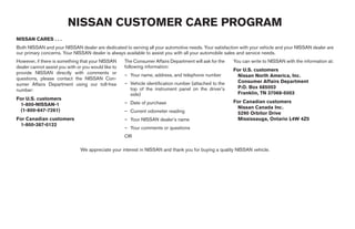
FOREWORD                                              READ FIRST—THEN DRIVE SAFELY


Welcome to the growing family of new NISSAN           Before driving your vehicle please read this Own-     ● ALWAYS review this Owner’s Manual
owners. This vehicle is delivered to you with         er’s Manual carefully. This will ensure familiarity     for important safety information.
confidence. It was produced using the latest          with controls and maintenance requirements, as-
techniques and strict quality control.                sisting you in the safe operation of your vehicle.    MODIFICATION OF YOUR VEHICLE
This manual was prepared to help you under-                                                                 This vehicle should not be modified.
stand the operation and maintenance of your                                WARNING                          Modification      could      affect  its
vehicle so that you may enjoy many miles (kilome-     IMPORTANT SAFETY INFORMATION RE-                      performance, safety or durability, and
ters) of driving pleasure. Please read through this   MINDERS FOR SAFETY!                                   may     even     violate    governmental
manual before operating your vehicle.                                                                       regulations. In addition, damage or per-
                                                      Follow these important driving rules to
A separate Warranty Information Booklet               help ensure a safe and complete trip for              formance problems resulting from modi-
explains details about the warranties cov-            you and your passengers!                              fications may not be covered under
ering your vehicle. The “NISSAN Service                                                                     NISSAN warranties.
                                                      ● NEVER drive under the influence of al-
and Maintenance Guide” explains details
                                                        cohol or drugs.
about maintaining and servicing your ve-
hicle. Additionally, a separate Customer              ● ALWAYS observe posted speed limits
Care/Lemon Law Booklet (U.S. only) will                 and never drive too fast for conditions.
explain how to resolve any concerns you
                                                      ● ALWAYS give your full attention to driv-
may have with your vehicle, as well as
                                                        ing and avoid using vehicle features or
clarify your rights under your state’s lemon
                                                        taking other actions that could distract
law.
                                                        you.
Your NISSAN dealership knows your vehicle             ● ALWAYS use your seat belts and appro-
best. When you require any service or have any          priate child restraint systems. Preteen
questions, they will be glad to assist you with the     children should be seated in the rear
extensive resources available to them.                  seat.
                                                      ● ALWAYS provide information about the
                                                        proper use of vehicle safety features to
                                                        all occupants of the vehicle.


                                                                                    ੬ REVIEW COPY—2008 Maxima (max)
                                                                                    Owners Manual—USA_English (nna)
                                                                                    06/08/07—debbie ੭
WHEN READING THE MANUAL


This manual includes information for all options                                                              CALIFORNIA PROPOSITION 65
available on this model. Therefore, you may find                                                              WARNING
some information that does not apply to your
vehicle.
                                                                                                                                WARNING
All information, specifications and illustrations in
                                                                                                              Engine exhaust, some of its constituents,
this manual are those in effect at the time of
                                                                                                              and certain vehicle components contain
printing. NISSAN reserves the right to change
                                                                                                              or emit chemicals known to the State of
specifications or design without notice and with-
                                                                                                              California to cause cancer and birth de-
out obligation.
                                                                                                              fects or other reproductive harm. In addi-
IMPORTANT INFORMATION ABOUT                                                                                   tion, certain fluids contained in vehicles
THIS MANUAL                                                                                                   and certain products of component wear
                                                                                                              contain or emit chemicals known to the
You will see various symbols in this manual. They                                                             State of California to cause cancer and
are used in the following ways:                                                                  APD1005      birth defects or other reproductive harm.
                                                       If you see this symbol, it means “Do not do this”      CALIFORNIA PERCHLORATE
                     WARNING
                                                       or “Do not let this happen.”
This is used to indicate the presence of a                                                                    ADVISORY
hazard that could cause death or serious                                                                      Some vehicle parts, such as lithium batter-
personal injury. To avoid or reduce the                If you see a symbol similar to these in an illustra-   ies, may contain perchlorate material. The
risk, the procedures must be followed                  tion, it means the arrow points to the front of the    following advisory is provided: “Perchlorate
precisely.                                             vehicle.                                               Material – special handling may apply, See
                                                                                                              www.dtsc.ca.gov/hazardouswaste/perchlorate.”
                      CAUTION
This is used to indicate the presence of a             Arrows in an illustration that are similar to these
hazard that could cause minor or moder-                indicate movement or action.
ate personal injury or damage to your ve-
hicle. To avoid or reduce the risk, the pro-
cedures must be followed carefully.                    Arrows in an illustration that are similar to these
                                                       call attention to an item in the illustration.


                                                                                      ੬ REVIEW COPY—2008 Maxima (max)
                                                                                      Owners Manual—USA_English (nna)
                                                                                      06/08/07—debbie ੭
BLUETOOTH௡ is a
                    trademark owned by
                    Bluetooth SIG, Inc.,
                    U.S.A. and licensed to
                    Visteon.


© 2007 NISSAN NORTH AMERICA, INC.
All rights reserved. No part of this Owner’s
Manual may be reproduced or stored in a retrieval
system, or transmitted in any form, or by any
means, electronic, mechanical, photocopying,
recording or otherwise, without the prior written
permission of Nissan North America, Inc.


                                                    ੬ REVIEW COPY—2008 Maxima (max)
                                                    Owners Manual—USA_English (nna)
                                                    06/08/07—debbie ੭
NISSAN CUSTOMER CARE PROGRAM
NISSAN CARES . . .
Both NISSAN and your NISSAN dealer are dedicated to serving all your automotive needs. Your satisfaction with your vehicle and your NISSAN dealer are
our primary concerns. Your NISSAN dealer is always available to assist you with all your automobile sales and service needs.
However, if there is something that your NISSAN      The Consumer Affairs Department will ask for the   You can write to NISSAN with the information at:
dealer cannot assist you with or you would like to   following information:
                                                                                                        For U.S. customers
provide NISSAN directly with comments or             – Your name, address, and telephone number          Nissan North America, Inc.
questions, please contact the NISSAN Con-
                                                     – Vehicle identification number (attached to the    Consumer Affairs Department
sumer Affairs Department using our toll-free
                                                       top of the instrument panel on the driver’s       P.O. Box 685003
number:
                                                       side)                                             Franklin, TN 37068-5003
For U.S. customers
                                                     – Date of purchase                                 For Canadian customers
 1-800-NISSAN-1
                                                                                                         Nissan Canada Inc.
 (1-800-647-7261)                                    – Current odometer reading                          5290 Orbitor Drive
For Canadian customers                               – Your NISSAN dealer’s name                         Mississauga, Ontario L4W 4Z5
 1-800-387-0122
                                                     – Your comments or questions
                                                     OR

                               We appreciate your interest in NISSAN and thank you for buying a quality NISSAN vehicle.


                                                                                  ੬ REVIEW COPY—2008 Maxima (max)
                                                                                  Owners Manual—USA_English (nna)
                                                                                  06/08/07—debbie ੭
Table of   Illustrated table of contents                                      0
Contents   Safety—Seats, seat belts and supplemental restraint system         1
           Instruments and controls                                           2
           Pre-driving checks and adjustments                                 3
           Display screen, heater, air conditioner, audio and phone systems   4
           Starting and driving                                               5
           In case of emergency                                               6
           Appearance and care                                                7
           Maintenance and do-it-yourself                                     8
           Technical and consumer information                                 9
           Index                                                              10
੬ REVIEW COPY—2008 Maxima (max)
Owners Manual—USA_English (nna)
06/08/07—debbie ੭
0 Illustrated table of contents


Airbags, seat belts and child restraints . . . . . . . . . . . . . . . 0-2                       Instrument panel. . . . . . . . . . . . . . . . . . . . . . . . . . . . . . . . . . . 0-6
Exterior front . . . . . . . . . . . . . . . . . . . . . . . . . . . . . . . . . . . . . . 0-3   Engine compartment check locations . . . . . . . . . . . . . . . . 0-8
Exterior rear. . . . . . . . . . . . . . . . . . . . . . . . . . . . . . . . . . . . . . . 0-4   Warning/indicator lights . . . . . . . . . . . . . . . . . . . . . . . . . . . . 0-9
Passenger compartment . . . . . . . . . . . . . . . . . . . . . . . . . . . 0-5


                                                                                                  ੬ REVIEW COPY—2008 Maxima (max)
                                                                                                  Owners Manual—USA_English (nna)
                                                                                                  06/08/07—debbie ੭
AIRBAGS, SEAT BELTS AND CHILD
RESTRAINTS

                                                     1.  Top tether strap anchor (P. 1-20)
                                                     2.  Rear head restraint (P. 1-7)
                                                     3.  Rear seat belts (P. 1-9)
                                                     4.  Roof mounted curtain side-impact
                                                         supplemental air bag (P. 1-35)
                                                     5. Front seat mounted side-impact
                                                         supplemental air bags (P. 1-35)
                                                     6. Front seat active head restraints
                                                         (P. 1-7, P. 1-8)
                                                     7. Front seat belts (P. 1-9)
                                                     8. Supplemental front impact air bags
                                                         (P. 1-35)
                                                     9. Seats (P. 1-2)
                                                     10. Occupant classification sensor
                                                         (pressure sensor) (P.1-43)
                                                     11. Seat belt pretensioners (P. 1-50)
                                                     12. LATCH (Lower Anchors and Tethers for
                                                         CHildren) (P. 1-19)
                                                     See the page number indicated in paren-
                                                     theses for operating details.


                                           LII0065

0-2 Illustrated table of contents


                                    ੬ REVIEW COPY—2008 Maxima (max)
                                    Owners Manual—USA_English (nna)
                                    06/08/07—debbie ੭
EXTERIOR FRONT


                                 1.    Engine hood (P. 3-18)
                                 2.    Headlight and turn signal switch
                                       (P. 2-22)
                                 3.    Replacing bulbs (P. 8-29)
                                 4.    Windshield wiper and washer switch
                                       (P. 2-20)
                                 5.    Windshield (P. 8-19)
                                 6.    Moonroof (if so equipped) (P. 2-39)
                                 7.    Power windows (P. 2-37)
                                 8.    Door locks, Intelligent key system, keys,
                                       request button (P. 3-4, 3-6, 3-2, 3-6)
                                 9.    Mirrors (P. 3-24)
                                 10.   Tire pressure (P. 8-31)
                                 11.   Flat tire (P. 6-2)
                                 12.   Tire chains (P. 8-39)
                                 13.   Cornering light (P. 2-27)
                                 14.   Fog light switch (P. 2-26)
                                 15.   Tie down hooks (P. 6-12)
                                 See the page number indicated in paren-
                                 theses for operating details.


                       WII0086

                                         Illustrated table of contents 0-3


                 ੬ REVIEW COPY—2008 Maxima (max)
                 Owners Manual—USA_English (nna)
                 06/08/07—debbie ੭
EXTERIOR REAR


                                                    1.  Rear window defroster switch (P. 2-21)
                                                    2.  Interior trunk lid release (P. 3-19)
                                                    3.  Trunk lid (P. 3-18)
                                                    4.  Vehicle loading (P. 9-12)
                                                    5.  Tie-down hook (P. 6-12)
                                                    6.  Exterior trunk lid release/request button
                                                        (P. 3-12)
                                                    7. Rear sonar system (P. 5-22)
                                                    8. Replacing bulbs (P. 8-29)
                                                    9. Fuel-filler cap, fuel recommendation
                                                        (P. 3-20, P. 9-3)
                                                    10. Fuel-filler door (P. 3-20)
                                                    11. Child safety locks (P. 3-6)
                                                    See the page number indicated in paren-
                                                    theses for operating details.


                                          WII0131

0-4 Illustrated table of contents


                                    ੬ REVIEW COPY—2008 Maxima (max)
                                    Owners Manual—USA_English (nna)
                                    06/08/07—debbie ੭
PASSENGER COMPARTMENT


                                        1.  Interior trunk access (P. 1-6)
                                        2.  Moonroof (if so equipped) (P. 2-39)
                                        3.  Sun visors (P. 3-23)
                                        4.  Interior lights, illuminated entry (P. 2-41)
                                        5.  HomeLinkா (if so equipped) (P. 2-43)
                                        6.  Automatic anti-glare inside mirror
                                            (if so equipped) (P. 3-24)
                                        7. Glove box (P. 2-34)
                                        8. Front cup holders (P. 2-33)
                                        9. Front console (P. 2-34)
                                        10. Front seat (P. 1-2)
                                        11. Rear seat (P. 1-6)
                                        See the page number indicated in paren-
                                        theses for operating details.


                              WII0126

                                                Illustrated table of contents 0-5


                        ੬ REVIEW COPY—2008 Maxima (max)
                        Owners Manual—USA_English (nna)
                        06/08/07—debbie ੭
INSTRUMENT PANEL


                                                                                               8.    Windshield wiper/washer switch
                                                                                                     (P. 2-20)
                                                                                               9.    Display screen/Navigation system*
                                                                                                     (P. 4-2, P. 4-6)
                                                                                               10.   Display screen/Navigation system*
                                                                                                     controls (P. 4-2, P. 4-6)
                                                                                               11.   Front passenger supplemental air bag
                                                                                                     (P. 1-35)
                                                                                               12.   Glove box (P. 2-34)
                                                                                               13.   Audio system controls (P. 4-22)
                                                                                               14.   Climate controls (P. 4-19)
                                                                                               15.   Storage (P. 2-32)
                                                                                               16.   Power outlet (P. 2-31)
                                                                                               17.   Shift selector lever (P. 5-9)
                                                                                               18.   Hazard warning flasher switch (P. 2-27)
                                                                                               19.   Passenger air bag status light (P. 1-45)
                                                                                               20.   Ignition switch (P. 5-6)
                                                                                               21.   Tilt/telescopic steering wheel controls
                                                                                                     (P. 3-22)
                                                                                               22.   Traction Control System (TCS) off
                                                                                     LIC0988         switch (if so equipped) (P. 2-29) or
                                                                                                     Vehicle Dynamic Control (VDC) off
1.   Side and center ventilators (P. 4-18)     4.   Meters and gauges (P. 2-3)
                                               5.   Driver supplemental air bag/horn                 switch (if so equipped) (P. 2-30)
2.   Headlight/fog light/turn signal switch
                                                                                               23.   Rear sonar system off switch
     (P. 2-22)                                      (P. 1-35, P. 2-28)
                                               6.   Security indicator light (P. 2-17)               (if so equipped) (P. 2-30)
3.   Steering wheel switch for audio control
                                               7.   Cruise control main/set switches           24.   Outside mirror controls (P. 3-25)
     and Bluetoothா Hands-Free Phone
                                                                                               25.   Instrument brightness control (P. 2-26)
     System (if so equipped) (P. 4-44, 4-46)        (P. 5-14)
0-6 Illustrated table of contents


                                                                          ੬ REVIEW COPY—2008 Maxima (max)
                                                                          Owners Manual—USA_English (nna)
                                                                          06/08/07—debbie ੭
*: Refer to the separate Navigation System Own-
er’s Manual (if so equipped).
See the page number indicated in paren-
theses for operating details.


                                                                    Illustrated table of contents 0-7


                                                  ੬ REVIEW COPY—2008 Maxima (max)
                                                  Owners Manual—USA_English (nna)
                                                  06/08/07—debbie ੭
ENGINE COMPARTMENT CHECK
LOCATIONS

                                                    1.  Power steering fluid reservoir (P. 8-11)
                                                    2.  Engine oil filler cap (P. 8-8)
                                                    3.  Brake fluid reservoir (P. 8-12)
                                                    4.  Air cleaner (P. 8-16)
                                                    5.  Battery (P. 8-13)
                                                    6.  Fuse/fusible link box (P. 8-21)
                                                    7.  Engine oil dipstick (P. 8-8)
                                                    8.  Radiator cap (P. 8-7)
                                                    9.  Drive belt location (P.8-15)
                                                    10. Fuse block (P. 8-21)
                                                    11. Windshield washer fluid reservoir
                                                        (P. 8-12)
                                                    12. Engine coolant reservoir (P. 8-7)
                                                    NOTE:
                                                    Engine cover removed for clarity.
                                                    See the page number indicated in paren-
                                                    theses for operating details.


                                          WDI0525

0-8 Illustrated table of contents


                                    ੬ REVIEW COPY—2008 Maxima (max)
                                    Owners Manual—USA_English (nna)
                                    06/08/07—debbie ੭
WARNING/INDICATOR LIGHTS


 Warning          Name            Page   Warning          Name            Page   Indicator          Name              Page
  light                                   light                                    light

           Anti-lock Braking      2-11             Low tire pressure      2-12               Continuously Vari-       2-14
   or      System (ABS) warn-                      warning light                             able Transmission
           ing light                                                                         (CVT) indicator light
                                                   Low windshield         2-13
                                                   washer fluid warning                      Continuously Vari-       2-15
           Brake warning light    2-11             light                                     able Transmission
   or                                                                                        (CVT) position indi-
                                                   P position selecting   2-13               cator light
                                                   warning light
                                                                                             CRUISE main              2-15
                                                   Seat belt warning      2-14               switch indicator light
           Charge warning         2-11
                                                   light and chime
           light
                                                                                             Cruise SET switch        2-15
                                                   Supplemental air       2-14               indicator light
           Door open warning      2-11
                                                   bag warning light
           light
                                                                                             Front passenger air      2-15
                                                   Trunk lid open warn-   2-14               bag status light
           Engine oil pressure    2-12
                                                   ing light
           warning light
                                                                                             High beam indicator      2-15
           Intelligent Key sys-   2-12                                                       light (blue)
           tem warning light
                                                                                             Malfunction indica-      2-15
           Low fuel warning       2-12                                                       tor light (MIL)
           light


                                                                                      Illustrated table of contents 0-9


                                                                ੬ REVIEW COPY—2008 Maxima (max)
                                                                Owners Manual—USA_English (nna)
                                                                06/08/07—debbie ੭
Indicator           Name               Page
    light

              Slip indicator light (if   2-16
              so equipped)

              Traction Control           2-16
              System off indicator
              light (if so equipped)

              Turn signal/hazard         2-16
              indicator lights

              Vehicle Dynamic            2-16
              Control off indicator
              light (if so equipped)


0-10 Illustrated table of contents


                                                ੬ REVIEW COPY—2008 Maxima (max)
                                                Owners Manual—USA_English (nna)
                                                06/08/07—debbie ੭
1 Safety—Seats, seat belts and
supplemental restraint system

Seats . . . . . . . . . . . . . . . . . . . . . . . . . . . . . . . . . . . . . . . . . . . . 1-2   Child restraints . . . . . . . . . . . . . . . . . . . . . . . . . . . . . . . . . . . 1-17
  Front manual seat adjustment —                                                                       Precautions on child restraints . . . . . . . . . . . . . . . . . . 1-17
  passenger’s side . . . . . . . . . . . . . . . . . . . . . . . . . . . . . . . 1-2                   Lower Anchors and Tethers for CHildren
  Front power seat adjustment                                                                          System (LATCH) . . . . . . . . . . . . . . . . . . . . . . . . . . . . . . 1-19
  (for driver’s seat and if so equipped for                                                            Top tether strap child restraint . . . . . . . . . . . . . . . . . . 1-20
  passenger’s seat) . . . . . . . . . . . . . . . . . . . . . . . . . . . . . . 1-4
                                                                                                       Child restraint installation using LATCH . . . . . . . . . . 1-21
  Folding rear seat . . . . . . . . . . . . . . . . . . . . . . . . . . . . . . . 1-6
                                                                                                       Child restraint installation using the seat
  Head restraint adjustment . . . . . . . . . . . . . . . . . . . . . . . 1-7
                                                                                                       belts . . . . . . . . . . . . . . . . . . . . . . . . . . . . . . . . . . . . . . . . . 1-25
  Front-Seat Active Head Restraints. . . . . . . . . . . . . . . . 1-8
                                                                                                    Booster seats . . . . . . . . . . . . . . . . . . . . . . . . . . . . . . . . . . . . 1-31
Seat belts . . . . . . . . . . . . . . . . . . . . . . . . . . . . . . . . . . . . . . . . 1-9
                                                                                                       Precautions on booster seats . . . . . . . . . . . . . . . . . . . 1-31
  Precautions on seat belt usage. . . . . . . . . . . . . . . . . . . 1-9
                                                                                                       Booster seat installation . . . . . . . . . . . . . . . . . . . . . . . . 1-33
  Child safety . . . . . . . . . . . . . . . . . . . . . . . . . . . . . . . . . . . 1-11
  Pregnant women . . . . . . . . . . . . . . . . . . . . . . . . . . . . . . 1-13                   Supplemental restraint system . . . . . . . . . . . . . . . . . . . . . 1-35
  Injured persons. . . . . . . . . . . . . . . . . . . . . . . . . . . . . . . . 1-13                  Precautions on supplemental restraint
  Three-point type seat belt with retractor . . . . . . . . . . 1-13                                   system . . . . . . . . . . . . . . . . . . . . . . . . . . . . . . . . . . . . . . . 1-35
  Seat belt extenders . . . . . . . . . . . . . . . . . . . . . . . . . . . . 1-16                     Supplemental air bag warning labels . . . . . . . . . . . . . 1-51
  Seat belt maintenance . . . . . . . . . . . . . . . . . . . . . . . . . 1-16                         Supplemental air bag warning light . . . . . . . . . . . . . . 1-51


                                                                                                     ੬ REVIEW COPY—2008 Maxima (max)
                                                                                                     Owners Manual—USA_English (nna)
                                                                                                     06/08/07—debbie ੭
SEATS


                                                                                          FRONT MANUAL SEAT
                                                                                          ADJUSTMENT — PASSENGER’S
                                                                                          SIDE


                                                                               ARS1152

                WARNING                     ● For the most effective protection when
                                              the vehicle is in motion, the seat should
● Do not ride in a moving vehicle when        be upright. Always sit well back in the
  the seatback is reclined. This can be       seat with both feet on the floor and
  dangerous. The shoulder belt will not       adjust the seat properly. See “Precau-
  be against your body. In an accident,       tions on Seat Belt Usage” later in this
  you could be thrown into it and receive     section.
  neck or other serious injuries. You
  could also slide under the lap belt and   ● After adjustment, gently rock in the seat
  receive serious internal injuries.          to make sure it is securely locked.
                                            ● Do not leave children unattended inside
                                              the vehicle. They could unknowingly ac-
                                              tivate switches or controls. Unattended
                                              children could become involved in seri-
                                              ous accidents.

1-2 Safety—Seats, seat belts and supplemental restraint system


                                                                      ੬ REVIEW COPY—2008 Maxima (max)
                                                                      Owners Manual—USA_English (nna)
                                                                      06/08/07—debbie ੭
LRS0244                                                LRS0245
Forward and backward                                Reclining
Pull the lever up and hold it while you slide the   To recline the seatback, pull the lever up and lean
seat forward or backward to the desired position.   back. To bring the seatback forward, pull the lever
Release the lever to lock the seat in position.     up and lean your body forward. Release the lever
                                                    to lock the seatback in position.
                                                    The reclining feature allows adjustment of the
                                                    seatback for occupants of different sizes for
                                                    added comfort and to help obtain proper seat
                                                    belt fit. See “Precautions on seat belt usage” later
                                                    in this section. Also, the seatback can be reclined
                                                    to allow occupants to rest when the vehicle is
                                                    stopped and the transmission is in P (Park).


                                                                           Safety—Seats, seat belts and supplemental restraint system 1-3


                                                                                   ੬ REVIEW COPY—2008 Maxima (max)
                                                                                   Owners Manual—USA_English (nna)
                                                                                   06/08/07—debbie ੭
The reclining feature allows adjustment of the
                                                                                                     seatback for occupants of different sizes for
                                                                                                     added comfort and to help obtain proper seat
                                                                                                     belt fit (see “Precautions on seat belt usage” later
                                                                                                     in this section). Also, the seatback can be re-
                                                                                                     clined to allow occupants to rest when the ve-
                                                                                                     hicle is stopped and the transmission is in P
                                                                                                     (Park).


                                                                                        WRS0163

FRONT POWER SEAT                                 See “Automatic drive positioner (if so equipped)”
ADJUSTMENT (for driver’s seat and if             in “Pre-driving checks and adjustments” for auto-
                                                 matic drive positioner operation.
so equipped for passenger’s seat)
                                                 Forward and backward
Operating tips
                                                 Moving the switch forward or backward will slide
 ● The power seat motor has an auto-reset        the seat forward or backward to the desired
   overload protection circuit. If the motor     position.
   stops during operation, wait 30 seconds,
   then reactivate the switch.                   Reclining
 ● Do not operate the power seat switch for a    Move the recline switch backward until the de-
   long period of time when the engine is off.   sired angle is obtained. To bring the seatback
   This will discharge the battery.              forward again, move the switch forward and
                                                 move your body forward. The seatback will move
                                                 forward.
1-4 Safety—Seats, seat belts and supplemental restraint system


                                                                              ੬ REVIEW COPY—2008 Maxima (max)
                                                                              Owners Manual—USA_English (nna)
                                                                              06/08/07—debbie ੭
WRS0164                                            LRS0239                              LRS0238

Seat lifter (driver’s seat)                                          Manual                                    Power

Push the front or rear end of the switch up or
                                                  Lumbar support (driver’s seat)
down to adjust the angle and height of the seat   The lumbar support feature provides lower back
cushion.                                          support to the driver. Move the lever up or down
                                                  (manual) or move the switch forward or backward
                                                  (power) to adjust the seat lumbar area.


                                                                       Safety—Seats, seat belts and supplemental restraint system 1-5


                                                                              ੬ REVIEW COPY—2008 Maxima (max)
                                                                              Owners Manual—USA_English (nna)
                                                                              06/08/07—debbie ੭
᭺
                                                    1   Push down on the button on the rear parcel   ● Closely supervise children when they
                                                        shelf.                                         are around cars to prevent them from
                                                    ᭺
                                                    2   Fold down the passenger side seatback.         playing and becoming locked in the
                                                                                                       trunk where they could be seriously in-
                                                                      WARNING                          jured. Keep the car locked, with the rear
                                                                                                       seatback and trunk lid securely latched
                                                    ● Never allow anyone to ride in the cargo          when not in use, and prevent children’s
                                                      area or on the rear seat when it is in the       access to car keys.
                                                      fold-down position. Use of these areas
                                                      by passengers without proper restraints
                                                      could result in serious injury in an acci-
                                                      dent or sudden stop.
                                                    ● Properly secure all cargo with ropes or
                                                      straps to help prevent it from sliding or
                                                      shifting. Do not place cargo higher than
                                                      the seatbacks. In a sudden stop or col-
                                                      lision, unsecured cargo could cause
                                                      personal injury.
                                                    ● When returning the seatbacks to the
                                                      upright position, be certain they are
                                                      completely secured in the latched posi-
                                                      tion. If they are not completely secured,
                                        LRS0246       passengers may be injured in an acci-
                                                      dent or sudden stop.
FOLDING REAR SEAT
Interior trunk access
For models without rear center console, the trunk
can be accessed from the passenger side of the
rear seat for loading and unloading, as shown.
1-6 Safety—Seats, seat belts and supplemental restraint system


                                                                               ੬ REVIEW COPY—2008 Maxima (max)
                                                                               Owners Manual—USA_English (nna)
                                                                               06/08/07—debbie ੭
LRS0247                                                 LIC0401                                          WRS0133
To fold down the driver side of the rear seat, reach   Center armrest                                                        Type A — Front
through the opening and pull on the strap ᭺       1
                                                                                                             HEAD RESTRAINT ADJUSTMENT
located behind the seat.                               Pull the armrest down until it is horizontal.
                                                                                                             To raise the head restraint, pull it up. To lower,
The rear seats can be locked using the mechani-
                                                                                                             push and hold the lock knob and push the head
cal key to prevent unauthorized access.
                                                                                                             restraint down.

                                                                                                                                 WARNING
                                                                                                             Head restraints should be adjusted prop-
                                                                                                             erly as they may provide significant pro-
                                                                                                             tection against injury in an accident. Do
                                                                                                             not remove them. Check the adjustment
                                                                                                             after someone else uses the seat.


                                                                              Safety—Seats, seat belts and supplemental restraint system 1-7


                                                                                      ੬ REVIEW COPY—2008 Maxima (max)
                                                                                      Owners Manual—USA_English (nna)
                                                                                      06/08/07—debbie ੭
LRS0240                        WRS0134                                       SPA1025
               Type B — Rear                                                    FRONT-SEAT ACTIVE HEAD
Adjust the head restraint so the center is level                                RESTRAINTS
with the center of your ears.
                                                                                                  WARNING
                                                                                ● Always adjust the head restraints prop-
                                                                                  erly as specified in this section. Failure
                                                                                  to do so can reduce the effectiveness of
                                                                                  the Active Head Restraint.
                                                                                ● Active Head Restraints are designed to
                                                                                  supplement other safety systems. Al-
                                                                                  ways wear seat belts. No system can
                                                                                  prevent all injuries in any accident.


1-8 Safety—Seats, seat belts and supplemental restraint system


                                                                 ੬ REVIEW COPY—2008 Maxima (max)
                                                                 Owners Manual—USA_English (nna)
                                                                 06/08/07—debbie ੭
SEAT BELTS


● Do not attach anything to the head re-
  straint stalks. Doing so could impair
  Active Head Restraint function.
The Active Head Restraint moves forward utiliz-
ing the force that the seatback receives from the
occupant in a rear-end collision. The movement
of the head restraint helps support the occu-
pant’s head by reducing its backward movement
and helping absorb some of the forces that may
lead to whiplash type injuries.
Active Head Restraints are effective for collisions
at low to medium speeds in which it is said that
whiplash injury occurs most.
                                                                                                                                    SSS0136
Active Head Restraints operate only in certain
rear-end collisions. After the collision, the head    PRECAUTIONS ON SEAT BELT
restraints return to their original positions.        USAGE
Properly adjust the Active Head Restraints as         If you are wearing your seat belt properly ad-
described earlier in this section.                    justed and you are sitting upright and well back in
                                                      your seat with both feet on the floor, your chances
                                                      of being injured or killed in an accident and/or the
                                                      severity of injury may be greatly reduced.
                                                      NISSAN strongly encourages you and all of your
                                                      passengers to buckle up every time you drive,
                                                      even if your seating position includes a supple-
                                                      mental air bag.
                                                      Most U.S. states and Canadian provinces
                                                      or territories specify that seat belts be worn
                                                      at all times when a vehicle is being driven.

                                                                             Safety—Seats, seat belts and supplemental restraint system 1-9


                                                                                     ੬ REVIEW COPY—2008 Maxima (max)
                                                                                     Owners Manual—USA_English (nna)
                                                                                     06/08/07—debbie ੭
SSS0134                                       SSS0016

                 WARNING                                                                            WARNING
● Every person who drives or rides in this                                        ● The seat belt should be properly ad-
  vehicle should use a seat belt at all                                             justed to a snug fit. Failure to do so may
  times. Children should be properly re-                                            reduce the effectiveness of the entire
  strained in the rear seat and, if appro-                                          restraint system and increase the
  priate, in a child restraint.                                                     chance or severity of injury in an acci-
                                                                                    dent. Serious injury or death can occur
                                                                                    if the seat belt is not worn properly.


1-10 Safety—Seats, seat belts and supplemental restraint system


                                                                  ੬ REVIEW COPY—2008 Maxima (max)
                                                                  Owners Manual—USA_English (nna)
                                                                  06/08/07—debbie ੭
● Be sure the seat belt tongue is securely    ● All seat belt assemblies, including re-
                                                fastened to the proper buckle.                tractors and attaching hardware,
                                                                                              should be inspected after any collision
                                              ● Do not wear the seat belt inside out or
                                                                                              by a NISSAN dealer. NISSAN recom-
                                                twisted. Doing so may reduce its
                                                                                              mends that all seat belt assemblies in
                                                effectiveness.
                                                                                              use during a collision be replaced un-
                                              ● Do not allow more than one person to          less the collision was minor and the
                                                use the same seat belt.                       belts show no damage and continue to
                                              ● Never carry more people in the vehicle        operate properly. Seat belt assemblies
                                                than there are seat belts.                    not in use during a collision should also
                                                                                              be inspected and replaced if either
                                              ● If the seat belt warning light glows con-     damage or improper operation is noted.
                                                tinuously while the ignition is turned
                                                ON with all doors closed and all seat       ● All child restraints and attaching hard-
                                   SSS0014      belts fastened, it may indicate a mal-        ware should be inspected after any col-
                                                function in the system. Have the system       lision. Always follow the restraint
                 WARNING                        checked by a NISSAN dealer.                   manufacturer’s inspection instructions
                                                                                              and replacement recommendations.
● Always route the shoulder belt over         ● Once the pretensioner has activated, it       The child restraints should be replaced
  your shoulder and across your chest.          cannot be reused and must be replaced         if they are damaged.
  Never run the belt behind your back,          together with the retractor. See your
  under your arm or across your neck. The       NISSAN dealer.                              CHILD SAFETY
  belt should be away from your face and
  neck, but not falling off your shoulder.    ● Removal and installation of the seat        Children need adults to help protect them.
                                                belt pretensioner components should         They need to be properly restrained.
● Position the lap belt as low and snug as      be done by a NISSAN dealer.
  possible AROUND THE HIPS, NOT THE                                                         In addition to the general information in this
  WAIST. A lap belt worn too high could                                                     manual, child safety information is available from
  increase the risk of internal injuries in                                                 many other sources, including doctors, teachers,
  an accident.                                                                              government traffic safety offices, and community
                                                                                            organizations. Every child is different, so be sure
                                                                                            to learn the best way to transport your child.
                                                               Safety—Seats, seat belts and supplemental restraint system 1-11


                                                                        ੬ REVIEW COPY—2008 Maxima (max)
                                                                        Owners Manual—USA_English (nna)
                                                                        06/08/07—debbie ੭
There are three basic types of child restraint         for infants and small children. See “Child Re-         facing child restraint. Refer to the manufacturer’s
systems:                                               straints” later in this section.                       instructions for minimum and maximum weight
                                                                                                              and height recommendations. NISSAN recom-
 ● Rear facing child restraint                         Also, there are other types of child restraints
                                                                                                              mends that small children be placed in child
                                                       available for larger children for additional protec-
 ● Front facing child restraint                                                                               restraints that comply with Federal Motor Vehicle
                                                       tion.
                                                                                                              Safety Standards or Canadian Motor Vehicle
 ● Booster seat
                                                       NISSAN recommends that all pre-teens                   Safety Standards. You should choose a child
The proper restraint depends on the child’s size.      and children be restrained in the rear seat.           restraint that fits your vehicle and always follow
Generally, infants up to about 1 year and less         According to accident statistics, children             the manufacturer’s instructions for installation
than 20 pounds (9 kg) should be placed in rear         are safer when properly restrained in the              and use.
facing child restraints. Front facing child re-        rear seat than in the front seat.
straints are available for children who outgrow                                                               Larger children
                                                       This is especially important because your
rear facing child restraints and are at least 1 year   vehicle has a supplemental restraint sys-              Children who are too large for child restraints
old. Booster seats are used to help position a         tem (Air bag system) for the front passen-             should be seated and restrained by the seat belts
vehicle lap/shoulder belt on a child who can no        ger. See “Supplemental restraint system”               which are provided. The seat belt may not fit
longer use a front facing child restraint.             later in this section.                                 properly if the child is less than 4 feet 9 inches
                                                                                                              (142.5 cm) tall and weighs between 40 lbs (18
                     WARNING                           Infants                                                kg) and 80 lbs (36 kg). A booster seat should be
                                                       Infants up to at least 1 year old should be placed     used to obtain proper seat belt fit.
Infants and children need special protec-
tion. The vehicle’s seat belts may not fit             in a rear facing child restraint. NISSAN recom-        NISSAN recommends that a child be placed in a
them properly. The shoulder belt may                   mends that infants be placed in child restraints       commercially available booster seat if the shoul-
come too close to the face or neck. The                that comply with Federal Motor Vehicle Safety          der belt in the child’s seating position fits close to
lap belt may not fit over their small hip              Standards or Canadian Motor Vehicle Safety             the face or neck or if the lap portion of the seat
bones. In an accident, an improperly fit-              Standards. You should choose a child restraint         belt goes across the abdomen. The booster seat
ting seat belt could cause serious or fatal            that fits your vehicle and always follow the manu-     should raise the child so that the shoulder belt is
injury. Always use appropriate child                   facturer’s instructions for installation and use.      properly positioned across the top, middle por-
restraints.                                                                                                   tion of the shoulder and the lap belt is low on the
                                                       Small Children
                                                                                                              hips. A booster seat can only be used in seating
All U.S. states and Canadian provinces or terri-       Children that are over one year old and weigh at       positions that have a three-point type seat belt.
tories require the use of approved child restraints    least 20 lbs (9 kg) can be placed in a forward         The booster seat should fit the vehicle seat and
1-12 Safety—Seats, seat belts and supplemental restraint system


                                                                                      ੬ REVIEW COPY—2008 Maxima (max)
                                                                                      Owners Manual—USA_English (nna)
                                                                                      06/08/07—debbie ੭
have a label certifying that it complies with Fed-   THREE-POINT TYPE SEAT BELT
eral Motor Vehicle Safety Standards or Canadian      WITH RETRACTOR
Motor Vehicle Safety Standards. Once the child
has grown so the shoulder belt is no longer on or
                                                                      WARNING
near the face and neck, use the shoulder belt
without the booster seat.                            ● Every person who drives or rides in this
                                                       vehicle should use a seat belt at all
                    WARNING                            times.
Never let a child stand or kneel on any              ● Do not ride in a moving vehicle when
seat and do not allow a child in the cargo             the seatback is reclined. This can be
areas while the vehicle is moving. The                 dangerous. The shoulder belt will not
child could be seriously injured or killed in          be against your body. In an accident,
an accident or sudden stop.                            you could be thrown into it and receive
                                                       neck or other serious injuries. You
PREGNANT WOMEN                                         could also slide under the lap belt and                                           WRS0174
                                                       receive serious internal injuries.                   Manual front seat shown
NISSAN recommends that pregnant women use
seat belts. The seat belt should be worn snug,       ● For the most effective protection when      Fastening the seat belts
and always position the lap belt as low as pos-        the vehicle is in motion, the seat should
sible around the hips, not the waist. Place the        be upright. Always sit well back in the
                                                                                                   ᭺
                                                                                                   1   Adjust the seat. See “Seats” earlier in this
                                                                                                       section.
shoulder belt over your shoulder and across your       seat with both feet on the floor and
chest. Never run the lap/shoulder belt over your       adjust the seat belt properly.
abdominal area. Contact your doctor for specific
recommendations.
INJURED PERSONS
NISSAN recommends that injured persons use
seat belts. Check with your doctor for specific
recommendations.


                                                                      Safety—Seats, seat belts and supplemental restraint system 1-13


                                                                               ੬ REVIEW COPY—2008 Maxima (max)
                                                                               Owners Manual—USA_English (nna)
                                                                               06/08/07—debbie ੭
The Emergency Locking Retractor (ELR) mode
                                                                                                         allows the seat belt to extend and retract to allow
                                                                                                         the driver and passengers some freedom of
                                                                                                         movement in the seat. The ELR locks the seat belt
                                                                                                         when the vehicle slows down rapidly of during
                                                                                                         impacts.
                                                                                                         The Automatic Locking Retractor (ALR) mode or
                                                                                                         child restraint mode locks the seat belt for child
                                                                                                         restraint installation.
                                                                                                         When the ALR is activated, the seat belt cannot
                                                                                                         be extended again until the seat belt tongue is
                                                                                                         detached from the buckle and fully retracted.
                                                                                                         After the seat belt fully retracts, the seat belt
                                        WRS0137                                             WRS0138
                                                                                                         returns to the Emergency Locking Retractor
᭺
2   Slowly pull the seat belt out of the retractor   ᭺
                                                     3   Position the lap belt portion low and snug      (ELR) mode. See “Child restraints” later in this
    and insert the tongue into the buckle until          on the hips as shown.                           section for more information.
    you hear and feel the latch engage.
                                                     ᭺
                                                     4   Pull the shoulder belt portion toward the       The ALR should be used only for child re-
 ● The retractor is designed to lock during              retractor to take up extra slack. Be sure the
                                                                                                         straint installation. During normal seat belt
   a sudden stop or on impact. A slow                    shoulder belt is routed over your shoulder
                                                                                                         use by a passenger, the locking mode
   pulling motion permits the seat belt to               and across your chest.
   move, and allows you some freedom of                                                                  should not be activated. If it is activated it
                                                     The front passenger seat and the rear seating       may cause uncomfortable seat belt ten-
   movement in the seat.
                                                     positions three-point seat belts have two modes     sion. It can also change the operation of
 ● If the seat belt cannot be pulled from            of operation:                                       the front passenger air bag. See “Front
   its fully retracted position, firmly pull                                                             passenger air bag status light” later in this
                                                      ● Emergency Locking Retractor (ELR)
   the belt and release it. Then smoothly                                                                section.
   pull the belt out of the retractor.                ● Automatic Locking Retractor (ALR).


1-14 Safety—Seats, seat belts and supplemental restraint system


                                                                                  ੬ REVIEW COPY—2008 Maxima (max)
                                                                                  Owners Manual—USA_English (nna)
                                                                                  06/08/07—debbie ੭
To increase your confidence in the seat belts,
                 WARNING
                                                                                                   check the operation as follows.
When fastening the seat belts, be certain
that the seatbacks are completely se-                                                               ● Grasp the shoulder belt and pull forward
cured in the latched position. If they are                                                            quickly. The retractor should lock and re-
not completely secured, passengers may                                                                strict further belt movement.
be injured in an accident or sudden stop.                                                          If the retractor does not lock during this check or
                                                                                                   if you have any questions about seat belt opera-
                                                                                                   tion, see a NISSAN dealer.


                                                                                      WRS0139
                                             Unfastening the seat belts
                                             ᭺
                                             1   To unfasten the seat belt, press the button on
                                                 the buckle. The seat belt automatically re-
                                                 tracts.
                                             Checking seat belt operation
                                             Seat belt retractors are designed to lock seat belt
                                             movement by two separate methods:
                                              ● When the seat belt is pulled quickly from the
                                                retractor.
                                              ● When the vehicle slows down rapidly.


                                                                  Safety—Seats, seat belts and supplemental restraint system 1-15


                                                                           ੬ REVIEW COPY—2008 Maxima (max)
                                                                           Owners Manual—USA_English (nna)
                                                                           06/08/07—debbie ੭
WARNING                          ● Adults and children who can use the
                                                                                                              standard seat belt should not use an
                                                      ● After adjustment, release the adjust-                 extender. Such unnecessary use could
                                                        ment button and try to move the shoul-                result in serious personal injury in the
                                                        der belt anchor up and down to make                   event of an accident.
                                                        sure it is securely fixed in position.
                                                                                                            ● Never use seat belt extenders to install
                                                      ● The shoulder belt anchor height should                child restraints. If the child restraint is
                                                        be adjusted to the position best for you.             not secured properly, the child could be
                                                        Failure to do so may reduce the effec-                seriously injured in a collision or a sud-
                                                        tiveness of the entire restraint system               den stop.
                                                        and increase the chance or severity of
                                                        injury in an accident.                              SEAT BELT MAINTENANCE
                                                      SEAT BELT EXTENDERS                                   ● To clean the seat belt webbing, apply a
                                          LRS0242                                                             mild soap solution or any solution recom-
                                                      If, because of body size or driving position, it is     mended for cleaning upholstery or carpet.
Shoulder belt height adjustment (Front                not possible to properly fit the lap-shoulder belt      Then wipe with a cloth and allow the seat belts
seats)                                                and fasten it, an extender is available which is        to dry in the shade. Do not allow the seat belts
                                                      compatible with the installed seat belts. The ex-       to retract until they are completely dry.
The shoulder belt anchor height should be ad-
                                                      tender adds approximately 8 in (200 mm) of
justed to the position best for you. (See “Precau-                                                          ● If dirt builds up in the shoulder belt
                                                      length and may be used for either the driver or
tions on seat belt usage” earlier in this section.)                                                           guide of the seat belt anchors, the seat
                                                      front passenger seating position. See a NISSAN
To adjust, pull out the adjustment button ᭺ and
                                            1                                                                 belts may retract slowly. Wipe the shoulder
                                                      dealer for assistance if an extender is required.
move the shoulder belt anchor to the desired                                                                  belt guide with a clean, dry cloth.
position ᭺, so the belt passes over the center of
          2
                                                                           WARNING                          ● Periodically check to see that the seat
the shoulder. The belt should be away from your
                                                      ● Only NISSAN seat belt extenders, made                 belt and the metal components, such as
face and neck, but not falling off your shoulder.
                                                        by the same company which made the                    buckles, tongues, retractors, flexible wires
Release the adjustment button to lock the shoul-                                                              and anchors, work properly. If loose parts,
der belt anchor into position.                          original equipment seat belts, should
                                                        be used with NISSAN seat belts.                       deterioration, cuts or other damage on the
                                                                                                              webbing is found, the entire seat belt as-
                                                                                                              sembly should be replaced.
1-16 Safety—Seats, seat belts and supplemental restraint system


                                                                                    ੬ REVIEW COPY—2008 Maxima (max)
                                                                                    Owners Manual—USA_English (nna)
                                                                                    06/08/07—debbie ੭
CHILD RESTRAINTS


                                                                                ● Even with the NISSAN Advanced Air
                                                                                  Bag System, never install a rear-facing
                                                                                  child restraint in the front seat. An in-
                                                                                  flating supplemental front air bag could
                                                                                  seriously injure or kill your child. A rear-
                                                                                  facing child restraint must only be used
                                                                                  in the rear seat.
                                                                                ● NISSAN recommends that the child re-
                                                                                  straint be installed in the rear seat. Ac-
                                                                                  cording to accident statistics, children
                                                                                  are safer when properly restrained in
                                                                                  the rear seat than in the front seat. If
                                                                                  you must install a front facing child re-
                       ARS1098                                      WRS0256       straint in the front seat, see “Child re-
                                                                                  straint installation using the seat belts”
PRECAUTIONS ON CHILD                               WARNING                        later in this section.
RESTRAINTS                                                                      ● Improper use or improper installation
                                 ● Infants and small children should al-
                                   ways be placed in an appropriate child         of a child restraint can increase the risk
                                   restraint while riding in the vehicle.         or severity of injury for both the child
                                   Failure to use a child restraint can re-       and other occupants of the vehicle and
                                   sult in serious injury or death.               can lead to serious injury or death in an
                                                                                  accident.
                                 ● Infants and small children should never
                                   be carried on your lap. It is not possible   ● Follow all of the child restraint manu-
                                   for even the strongest adult to resist the     facturer’s instructions for installation
                                   forces of a severe accident. The child         and use. When purchasing a child re-
                                   could be crushed between the adult and         straint, be sure to select one which will
                                   parts of the vehicle. Also, do not put the     fit your child and vehicle. It may not be
                                   same seat belt around both your child          possible to properly install some types
                                   and yourself.                                  of child restraints in your vehicle.

                                                   Safety—Seats, seat belts and supplemental restraint system 1-17


                                                           ੬ REVIEW COPY—2008 Maxima (max)
                                                           Owners Manual—USA_English (nna)
                                                           06/08/07—debbie ੭
● If the child restraint is not anchored          ● When your child restraint is not in use,                Several manufacturers offer child restraints for
  properly, the risk of a child being in-           keep it secured with the LATCH System                   infants and small children of various sizes. When
  jured in a collision or a sudden stop             or a seat belt to prevent it from being                 selecting any child restraint, keep the following
  greatly increases.                                thrown around in case of a sudden stop                  points in mind:
                                                    or accident.                                             ● Choose only a restraint with a label certifying
● Child restraint anchor points are de-
  signed to withstand only those loads                                                                         that it complies with Federal Motor Vehicle
  imposed by correctly fitted child re-                                  CAUTION                               Safety Standard 213 or Canadian Motor
  straints. Under no circumstances are                                                                         Vehicle Safety Standard 213.
                                                  Remember that a child restraint left in a
  they to be used for adult seat belts or         closed vehicle can become very hot.                        ● Check the child restraint in your vehicle to be
  harnesses.                                      Check the seating surface and buckles                        sure it is compatible with the vehicle’s seat
● Adjustable seatbacks should be posi-            before placing your child in the child                       and seat belt system.
  tioned to fit the child restraint, but as       restraint.
                                                                                                             ● If the child restraint is compatible with your
  upright as possible.                                                                                         vehicle, place your child in the child restraint
                                                  This vehicle is equipped with a universal child
● After attaching the child restraint, test it    restraint lower anchor system, referred to as the            and check the various adjustments to be
  before you place the child in it. Push it       Lower Anchors and Tethers for CHildren System                sure the child restraint is compatible with
  from side to side while holding the seat        or LATCH. Some child restraints include two rigid            your child. Choose a child restraint that is
  near the LATCH attachment or by the                                                                          designed for your child’s height and weight.
                                                  or webbing-mounted attachments that can be
  seat belt path. Try to tug it forward and                                                                    Always follow all recommended procedures.
                                                  connected to these lower anchors. For details,
  check to see if the belt holds the re-          see the “Lower Anchors and Tethers for CHildren           All U.S. states and Canadian provinces or
  straint in place. The child restraint           System (LATCH)” later in this section.                    territories require that infants and small
  should not move more than 1 inch (25                                                                      children be restrained in an approved child
  mm). If the restraint is not secure,            If you do not have a LATCH compatible child               restraint at all times while the vehicle is
  tighten the belt as necessary, or put the       restraint, the vehicle seat belts can be used. See        being operated.
  restraint in another seat and test it           “Child restraint installation using the seat belts”
  again. You may need to try a different          later in this section. In general, child restraints are
  child restraint. Not all child restraints fit   also designed to be installed with the lap portion
  in all types of vehicles.                       of a lap/shoulder seat belt.


1-18 Safety—Seats, seat belts and supplemental restraint system


                                                                                   ੬ REVIEW COPY—2008 Maxima (max)
                                                                                   Owners Manual—USA_English (nna)
                                                                                   06/08/07—debbie ੭
● Do not secure a child restraint in the
                                                                                                               center rear seating position using the
                                                                                                               LATCH anchors. The child restraint will
                                                                                                               not be secured properly.
                                                                                                             ● Child restraint anchor points are de-
                                                                                                               signed to withstand only those loads
                                                                                                               imposed by correctly fitted child re-
                                                                                                               straints. Under no circumstance are
                                                                                                               they to be used for adult seat belts or
                                                                                                               harnesses.


                                           WRS0718                                              WRS0700
       LATCH system anchor locations                             LATCH lower anchor location
LOWER ANCHORS AND TETHERS                                 LATCH lower anchor point locations
FOR CHILDREN SYSTEM (LATCH)                               The LATCH anchors are located at the rear of the
Your vehicle is equipped with special anchor              seat cushion near the seatback. A label is at-
points that are used with Lower Anchors and               tached to the seatback to help you locate the
Tethers for CHildren System (LATCH) compat-               LATCH anchors.
ible child restraints. This system may also be
referred to as the ISOFIX or ISOFIX compatible                               WARNING
system. With this system, you do not have to use
                                                          ● Attach LATCH compatible child re-
a vehicle seat belt to secure the child restraint.
                                                            straints only at the locations shown in
The LATCH anchor points are provided to install             the illustration. If a child restraint is not
child restraints in the rear outboard seating posi-         secured properly, your child could be
tions only. Do not attempt to install a child restraint     seriously injured or killed in an
in the center position using the LATCH anchors.             accident.

                                                                             Safety—Seats, seat belts and supplemental restraint system 1-19


                                                                                      ੬ REVIEW COPY—2008 Maxima (max)
                                                                                      Owners Manual—USA_English (nna)
                                                                                      06/08/07—debbie ੭
TOP TETHER STRAP CHILD
                                                                                                                 RESTRAINT
                                                                                                                 If the manufacturer of your child restraint requires
                                                                                                                 the use of a top tether strap, it must be secured to
                                                                                                                 the anchor point.

                                                                                                                                      WARNING
                                                                                                                 Child restraint anchor points are designed
                                                                                                                 to withstand only those loads imposed by
                                                                                                                 correctly fitted child restraints. Under no
                                                                                                                 circumstances are they to be used for
                                                                                                                 adult seat belts or harnesses.
                                            LRS0661                                                 LRS0662
   LATCH webbing-mounted attachment                            LATCH rigid-mounted attachment
Installing child restraint LATCH anchor                  LATCH child restraints generally require the use
                                                         of a top tether strap. See “Top tether strap child
attachments                                              restraint” later in this section for installation in-
LATCH compatible child restraints include two            structions.
rigid or webbing-mounted attachments that can            When installing a child restraint, carefully read
be connected to two anchors located at certain           and follow the instructions in this manual and
seating positions in your vehicle. With this sys-        those supplied with the child restraint. See “Child
tem, you do not have to use a vehicle seat belt to       restraint installation using LATCH” in this section.
secure the child restraint. Check your child re-
straint for a label stating that it is compatible with
LATCH. This information may also be in the in-
structions provided by the child restraint manu-
facturer.


1-20 Safety—Seats, seat belts and supplemental restraint system


                                                                                        ੬ REVIEW COPY—2008 Maxima (max)
                                                                                        Owners Manual—USA_English (nna)
                                                                                        06/08/07—debbie ੭
3. Position the top tether strap over the top of   ● The LATCH anchors are designed to
                                                           the seatback.                                     withstand only those loads imposed by
                                                        4. Secure the tether strap to the tether anchor      correctly fitted child restraints. Under
                                                           bracket that provides the straightest instal-     no circumstance are they to be used for
                                                           lation.                                           adult seat belts or harnesses.
                                                                                                           ● Inspect the lower anchors by inserting
                                                        5. Tighten the tether strap according to the
                                                                                                             your fingers into the lower anchor area
                                                           manufacturer’s instructions to remove any
                                                                                                             and feeling to make sure there are no
                                                           slack.                                            obstructions over the LATCH anchors,
                                                       If you have any questions when installing a           such as seat belt webbing or seat cush-
                                                       top tether strap child restraint on the rear          ion material. The child restraint will not
                                                       seat, consult your NISSAN dealer for de-              be secured properly if the LATCH an-
                                                       tails.                                                chors are obstructed.
                                           LRS0243
                                                       CHILD RESTRAINT INSTALLATION                        Front-facing
Top Tether Anchor Point Locations                      USING LATCH                                         Follow these steps to install a front-facing child
Anchor points ᭺ are located on the rear parcel
              1                                                                                            restraint using LATCH:
shelf.                                                                     WARNING                          1. Position the child restraint on the seat. Al-
Installing top tether strap                            ● Attach LATCH compatible child re-                     ways follow the child restraint manufactur-
                                                         straints only at the locations shown. For             er’s instructions.
First, secure the child restraint with the seat belt     the LATCH lower anchor locations, see
or LATCH (rear outboard seat positions only), as         “Lower Anchors and Tethers for CHil-
applicable.                                              dren System (LATCH)” in this section. If
                                                         a child restraint is not secured properly,
 1. Flip up the anchor cover from the anchor             your child could be seriously injured or
    point which is located directly behind the           killed in an accident.
    child seat.
 2. Remove the head restraint. Store it in a
    secure location.

                                                                           Safety—Seats, seat belts and supplemental restraint system 1-21


                                                                                    ੬ REVIEW COPY—2008 Maxima (max)
                                                                                    Owners Manual—USA_English (nna)
                                                                                    06/08/07—debbie ੭
LRS0663                                                LRS0664                                               LRS0671
    Front facing web-mounted – step 2                      Front facing rigid-mounted – step 2                           Front facing – step 4
 2. Secure the child restraint anchor attach-          interfering with the proper child restraint fit, try   4. For child restraints that are equipped with
    ments to the LATCH lower anchors. Check            another seating position or a different child re-         webbing mounted attachments, remove any
    to make sure the LATCH attachment is prop-         straint.                                                  additional slack from the anchor attach-
    erly attached to the lower anchors.                                                                          ments. Press downward and rearward firmly
                                                                                                                 in the center of the child restraint with your
 3. The back of the child restraint should be                                                                    knee to compress the vehicle seat cushion
    secured against the vehicle seat back..                                                                      and seatback while tightening the webbing
If necessary, adjust or remove the head restraint                                                                of the anchor attachments.
to obtain the correct child restraint fit. See “Head                                                          5. If the child restraint is equipped with a top
restraint adjustment” in this section. If the head                                                               tether strap, route the top tether strap and
restraint is removed, store it in a secure place. Be                                                             secure the tether strap to the tether anchor
sure to install the head restraint when the child                                                                point. See “Top tether strap child restraint” in
restraint is removed. If the seating position does                                                               this section.
not have an adjustable head restraint and it is
1-22 Safety—Seats, seat belts and supplemental restraint system


                                                                                      ੬ REVIEW COPY—2008 Maxima (max)
                                                                                      Owners Manual—USA_English (nna)
                                                                                      06/08/07—debbie ੭
7. Check to make sure the child restraint is
                                                            properly secured prior to each use. If the
                                                            child restraint is loose, repeat steps 3
                                                            through 6.
                                                        Rear-facing
                                                        Follow these steps to install a rear-facing child
                                                        restraint using LATCH System:
                                                         1. Position the child restraint on the seat. Al-
                                                            ways follow the child restraint manufactur-
                                                            er’s instructions.


                                          WRS0697                                                                                               LRS0665
            Front facing – step 6                                                                              Rear facing web-mounted – step 2
6. Before placing the child in the child restraint,                                                         2. Secure the child restraint anchor attach-
   hold the child restraint near the LATCH at-                                                                 ments to the LATCH lower anchors. Check
   tachment and use force to push the child                                                                    to make sure the LATCH attachment is prop-
   restraint from side to side, and tug it forward                                                             erly attached to the lower anchors.
   to make sure that it is securely held in place.
   It should not move more than 1 in (25 mm). If
   it does move more than 1 in (25 mm), pull
   again on the anchor attachments to further
   tighten the child restraint. If you are unable to
   properly secure the restraint, move the re-
   straint to another seating position and try
   again, or try a different child restraint. Not all
   child restraints fit in all types of vehicles.


                                                                            Safety—Seats, seat belts and supplemental restraint system 1-23


                                                                                     ੬ REVIEW COPY—2008 Maxima (max)
                                                                                     Owners Manual—USA_English (nna)
                                                                                     06/08/07—debbie ੭
LRS0666                                                LRS0673                                           LRS0674
    Rear facing rigid-mounted – step 2                           Rear facing – step 3                                   Rear facing – step 4
                                                                                                             5. Check to make sure the child restraint is
 3. For child restraints that are equipped with      4. Before placing the child in the child restraint,        properly secured prior to each use. If the
    webbing mounted attachments, remove any             hold the child restraint near the LATCH at-             child restraint is loose, repeat steps 2
    additional slack from the anchor attach-            tachment and use force to push the child                through 4.
    ments. Press downward and rearward firmly           restraint from side to side, and tug it forward
    in the center of the child restraint with your      to make sure that it is securely held in place.
    hand to compress the vehicle seat cushion           It should not move more than 1 in (25 mm). If
    and seatback while tightening the webbing           it does move more than 1 in (25 mm), pull
    of the anchor attachments.                          again on the anchor attachments to further
                                                        tighten the child restraint. If you are unable to
                                                        properly secure the restraint, move the re-
                                                        straint to another seating position and try
                                                        again, or try a different child restraint. Not all
                                                        child restraints fit in all types of vehicles.

1-24 Safety—Seats, seat belts and supplemental restraint system


                                                                                    ੬ REVIEW COPY—2008 Maxima (max)
                                                                                    Owners Manual—USA_English (nna)
                                                                                    06/08/07—debbie ੭
● NISSAN recommends that child re-            The instructions in this section apply to child
                                              straints be installed in the rear seat.     restraint installation using the vehicle seat belts in
                                              However, if you must install a forward      the rear seat or the front passenger seat.
                                              facing child restraint in the front pas-
                                              senger seat, move the passenger seat
                                              to the rearmost position. Also, be sure
                                              the front passenger air bag status light
                                              is illuminated to indicate the passenger
                                              air bag is OFF. See “Front passenger air
                                              bag and status light” later in this sec-
                                              tion for details.
                                            ● The three-point seat belt in your vehicle
                                              is equipped with an Automatic Locking
                                 WRS0256      Retractor (ALR) which must be used
                                              when installing a child restraint.
CHILD RESTRAINT INSTALLATION
                                            ● Failure to use the ALR mode will result
USING THE SEAT BELTS                          in the child restraint not being properly
                                              secured. The restraint could tip over or
                WARNING                       otherwise be unsecured and cause in-
● Even with the NISSAN Advanced Air           jury to the child in a sudden stop or
  Bag System, never install a rear-facing     collision. Also, it can change the opera-
  child restraint in the front passenger      tion of the front passenger air bag. See
  seat. Supplemental front air bags in-       “Front passenger air bag and status
  flate with great force. A rear-facing       light” later in this section.
  child restraint could be struck by the    ● A child restraint with a top tether strap
  supplemental front air bag in a crash       should not be used in the front passen-
  and could seriously injure or kill your     ger seat.
  child.


                                                             Safety—Seats, seat belts and supplemental restraint system 1-25


                                                                      ੬ REVIEW COPY—2008 Maxima (max)
                                                                      Owners Manual—USA_English (nna)
                                                                      06/08/07—debbie ੭
2. Position the child restraint on the seat. Al-
                                                         ways follow the child restraint manufactur-
                                                         er’s instructions
                                                     The back of the child restraint should be secured
                                                     against the vehicle seatback. If necessary, adjust
                                                     or remove the head restraint to obtain the correct
                                                     child restraint fit. See “Head restraint adjust-
                                                     ment” in this section.
                                                     If the head restraint is removed, store it in a
                                                     secure place. Be sure to install the head restraint
                                                     when the child restraint is removed. If the seating
                                                     position does not have an adjustable head re-
                                                     straint and it is interfering with the proper child
                                       WRS0699       restraint fit, try another seating position or a dif-                                            WRS0680
Front-facing (front passenger seat) – step 1         ferent child restraint.                                            Front facing – step 3
Front-facing                                                                                                 3. Route the seat belt tongue through the child
                                                                                                                restraint and insert it into the buckle until you
Follow these steps to install a front-facing child                                                              hear and feel the latch engage. Be sure to
restraint using the vehicle seat belt in the rear                                                               follow the child restraint manufacturer’s in-
seats or in the front passenger seat:                                                                           structions for belt routing.
 1. If you must install a child restraint in
    the front seat, it should be placed in a
    front-facing direction only. Move the
    seat to the rearmost position. Child
    restraints for infants must be used in
    the rear-facing direction and therefore
    must not be used in the front seat.


1-26 Safety—Seats, seat belts and supplemental restraint system


                                                                                    ੬ REVIEW COPY—2008 Maxima (max)
                                                                                    Owners Manual—USA_English (nna)
                                                                                    06/08/07—debbie ੭
LRS0667                                             LRS0668                                          WRS0681
            Front facing – step 4                               Front facing – step 5                               Front facing – step 6
4. Pull the shoulder belt until the belt is fully    5. Allow the seat belt to retract. Pull up on the   6. Remove any additional slack from the seat
   extended. At this time, the seat belt retractor      shoulder belt to remove any slack in the belt.      belt; press downward and rearward firmly in
   is in the Automatic Locking Retractor mode                                                               the center of the child restraint with your
   (child restraint mode). It reverts to Emer-                                                              knee to compress the vehicle seat cushion
   gency Locking Retractor mode when the                                                                    and seatback while pulling up on the seat
   seat belt is fully retracted.                                                                            belt.


                                                                        Safety—Seats, seat belts and supplemental restraint system 1-27


                                                                                 ੬ REVIEW COPY—2008 Maxima (max)
                                                                                 Owners Manual—USA_English (nna)
                                                                                 06/08/07—debbie ੭
8. Before placing the child in the child restraint,
                                                           hold the child restraint near the seat belt
                                                           path and use force to push the child restraint
                                                           from side to side, and tug it forward to make
                                                           sure that it is securely held in place. It should
                                                           not move more than 1 in (25 mm). If it does
                                                           move more than 1 in (25 mm), pull again on
                                                           the shoulder belt to further tighten the child
                                                           restraint. If you are unable to properly secure
                                                           the restraint, move the restraint to another
                                                           seating position and try again, or try a differ-
                                                           ent child restraint. Not all child restraints fit in
                                                           all types of vehicles.
                                                        9. Check that the retractor is in the Automatic
                                         WRS0698                                                                                                            LRS0316
                                                           Locking Retractor mode by trying to pull
            Front facing – step 7                          more seat belt out of the retractor. If you                         Front facing – step 11
 7. If the child restraint is equipped with a top          cannot pull any more belt webbing out of the           11. If the child restraint is installed in the front
    tether strap, route the top tether strap and           retractor, the retractor is in the Automatic               passenger seat, turn the ignition switch to
    secure the tether strap to the tether anchor           Locking Retractor mode.                                    the ON position. The front passenger air bag
    point (rear seat installation only). See “Top                                                                     status light          should illuminate. If this
                                                       10. Check to make sure the child restraint is                  light is not illuminated see ЉFront passenger
    tether strap child restraint” in this section.         properly secured prior to each use. If the
    Do not install child restraints that require the                                                                  air bag status lightЉ in this section. Move
                                                           seat belt is not locked, repeat steps 3                    the child restraint to another seating
    use of a top tether strap to seating positions         through 8.
    that do not have a top tether anchor.                                                                             position. Have the system checked by a
                                                                                                                      NISSAN dealer.
                                                                                                                  After the child restraint is removed and the seat
                                                                                                                  belt is fully retracted, the Automatic Locking Re-
                                                                                                                  tractor mode (child restraint mode) is canceled.


1-28 Safety—Seats, seat belts and supplemental restraint system


                                                                                        ੬ REVIEW COPY—2008 Maxima (max)
                                                                                        Owners Manual—USA_English (nna)
                                                                                        06/08/07—debbie ੭
WRS0256                                               WRS0682                                               LRS0669
            Rear-facing – step 1                                Rear facing – step 2                                   Rear facing – step 3
Rear-facing                                         2. Route the seat belt tongue through the child        3. Pull the shoulder belt until the belt is fully
                                                       restraint and insert it into the buckle until you      extended. At this time, the seat belt retractor
Follow these steps to install a rear-facing child      hear and feel the latch engage. Be sure to             is in the Automatic Locking Retractor mode
restraint using the vehicle seat belt in the rear      follow the child restraint manufacturer’s in-          (child restraint mode). It reverts to Emer-
seats:                                                 structions for belt routing.                           gency Locking Retractor mode when the
 1. Child restraints for infants must be                                                                      seat belt is fully retracted.
    used in the rear-facing direction and
    therefore must not be used in the front
    seat. Always follow the restraint manufac-
    turer’s instructions.


                                                                        Safety—Seats, seat belts and supplemental restraint system 1-29


                                                                                  ੬ REVIEW COPY—2008 Maxima (max)
                                                                                  Owners Manual—USA_English (nna)
                                                                                  06/08/07—debbie ੭
LRS0670                                            WRS0683                                                WRS0684
            Rear facing – step 4                                 Rear facing – step 5                                Rear facing – step 6
 4. Allow the seat belt to retract. Pull up on the   5. Remove any additional slack from the child       6. Before placing the child in the child restraint,
    shoulder belt to remove any slack in the belt.      restraint; press downward and rearward              hold the child restraint near the seat belt
                                                        firmly in the center of the child restraint to      path and use force to push the child restraint
                                                        compress the vehicle seat cushion and seat-         from side to side, and tug it forward to make
                                                        back while pulling up on the seat belt.             sure that it is securely held in place. It should
                                                                                                            not move more than 1 in (25 mm). If it does
                                                                                                            move more than 1 in (25 mm), pull again on
                                                                                                            the shoulder belt to further tighten the child
                                                                                                            restraint. If you are unable to properly secure
                                                                                                            the restraint, move the restraint to another
                                                                                                            rear seating position and try again, or try a
                                                                                                            different child restraint. Not all child re-
                                                                                                            straints fit in all types of vehicles.


1-30 Safety—Seats, seat belts and supplemental restraint system


                                                                                 ੬ REVIEW COPY—2008 Maxima (max)
                                                                                 Owners Manual—USA_English (nna)
                                                                                 06/08/07—debbie ੭
BOOSTER SEATS


 7. Check that the retractor is in the Automatic                                                    ● Infants and small children should never
    Locking Retractor mode by trying to pull                                                          be carried on your lap. It is not possible
    more seat belt out of the retractor. If you                                                       for even the strongest adult to resist the
    cannot pull any more seat belt webbing out                                                        forces of a severe accident. The child
    of the retractor, the retractor is in the Auto-                                                   could be crushed between the adult and
    matic Locking Retractor mode                                                                      parts of the vehicle. Also, do not put the
 8. Check to make sure that the child restraint is                                                    same seat belt around both your child
    properly secured prior to each use. If the belt                                                   and yourself.
    is not locked, repeat steps 3 through 6.                                                        ● NISSAN recommends that the booster
After the child restraint is removed and the seat                                                     seat be installed in the rear seat. Ac-
belt fully retracted, the Automatic Locking Re-                                                       cording to accident statistics, children
tractor mode (child restraint mode) is canceled.                                                      are safer when properly restrained in
                                                                                                      the rear seat than in the front seat. If
                                                                                         ARS1098      you must install a booster seat in the
                                                                                                      front seat, see “Booster seat installa-
                                                      PRECAUTIONS ON BOOSTER                          tion” in this section.
                                                      SEATS                                         ● A booster seat must only be installed in
                                                                                                      a seating position that has a
                                                                       WARNING                        lap/shoulder belt. Failure to use a
                                                      ● Infants and small children should al-         three-point type seat belt with a
                                                        ways be placed in an appropriate child        booster seat can result in a serious in-
                                                        restraint while riding in the vehicle.        jury in sudden stop or collision.
                                                        Failure to use a child restraint or         ● Improper use or improper installation
                                                        booster seat can result in serious injury     of a booster seat can increase the risk
                                                        or death.                                     or severity of injury for both the child
                                                                                                      and other occupants of the vehicle and
                                                                                                      can lead to serious injury or death in an
                                                                                                      accident.


                                                                       Safety—Seats, seat belts and supplemental restraint system 1-31


                                                                                ੬ REVIEW COPY—2008 Maxima (max)
                                                                                Owners Manual—USA_English (nna)
                                                                                06/08/07—debbie ੭
● Do not use towels, books, pillows or        ● After placing the child in the booster
  other items in place of a booster seat.       seat and fastening the seat belt, make
  Items such as these may move during           sure the shoulder portion of the belt is
  normal driving or a collision and result      away from the child’s face and neck and
  in serious injury or death. Booster seats     the lap portion of the belt does not
  are designed to be used with a                cross the abdomen.
  lap/shoulder belt. Booster seats are de-
                                              ● Do not put the shoulder belt behind the
  signed to properly route the lap and
                                                child or under the child’s arm. If you
  shoulder portions of the seat belt over
                                                must install a booster seat in the front
  the strongest portions of a child’s body
                                                seat, see “Booster seat installation”
  to provide the maximum protection dur-
                                                later in this section.
  ing a collision.
                                              ● When your booster seat is not in use,
● Follow all of the booster seat manufac-
                                                keep it secured with a seat belt to pre-
  turer’s instructions for installation and
                                                vent it from being thrown around in                                                LRS0455
  use. When purchasing a booster seat,
                                                case of a sudden stop or accident.         Booster seats of various sizes are offered by
  be sure to select one which will fit your
  child and vehicle. It may not be possible                                                several manufacturers. When selecting any
  to properly install some types of                            CAUTION                     booster seat, keep the following points in mind:
  booster seats in your vehicle.              Remember that a booster seat left in a        ● Choose only a booster seat with a label
● If the booster seat and seat belt is not    closed vehicle can become very hot.             certifying that it complies with Federal Motor
  used properly, the risk of a child being    Check the seating surface and buckles           Vehicle Safety Standard 213 or Canadian
  injured in a collision or a sudden stop     before placing your child in the booster        Motor Vehicle Safety Standard 213.
  greatly increases.                          seat.
                                                                                            ● Check the booster seat in your vehicle to be
● Adjustable seatbacks should be posi-                                                        sure it is compatible with the vehicle’s seat
  tioned to fit the booster seat, but as                                                      and seat belt system.
  upright as possible.


1-32 Safety—Seats, seat belts and supplemental restraint system


                                                                       ੬ REVIEW COPY—2008 Maxima (max)
                                                                       Owners Manual—USA_English (nna)
                                                                       06/08/07—debbie ੭
BOOSTER SEAT INSTALLATION
                                                                                                                          WARNING
                                                                                                        ● NISSAN recommends that booster
                                                                                                          seats be installed in the rear seat. How-
                                                                                                          ever, if you must install a booster seat in
                                                                                                          the front passenger seat, move the pas-
                                                                                                          senger’s seat to the rearmost position.

                                                                                                                           CAUTION
                                                                                                        Do not use the lap/shoulder belt Auto-
                                                                                                        matic Locking Retractor mode when using
                                                                                                        a booster seat with the seat belts.
                                        LRS0453                                             LRS0464
● Make sure the child’s head will be properly       All U.S. states and Canadian provinces or
  supported by the booster seat or vehicle          territories require that infants and small
  seat. The seat back must be at or above the       children be restrained in an approved child
  center of the child’s ears. For example, if a     restraint at all times while the vehicle is
  low back booster seat ᭺ is chosen, the
                             1                      being operated.
  vehicle seat back must be at or above the         The instructions in this section apply to booster
  center of the child’s ears. If the seat back is   seat installation in the rear seats or the front
  lower than the center of the child’s ears, a      passenger seat.
  high back booster seat ᭺ should be used.
                            2

● If the booster seat is compatible with your
  vehicle, place your child in the booster seat
  and check the various adjustments to be
  sure the booster seat is compatible with your
  child. Always follow all recommended pro-
  cedures.
                                                                        Safety—Seats, seat belts and supplemental restraint system 1-33


                                                                                 ੬ REVIEW COPY—2008 Maxima (max)
                                                                                 Owners Manual—USA_English (nna)
                                                                                 06/08/07—debbie ੭
WRS0699                             LRS0451                                            LRS0452
Follow these steps to install a booster seat in the   Rear center position                       Rear outboard position
rear seat or in the front passenger seat:                                              3. The booster seat should be positioned on
 1. If you must install a booster seat in the                                             the vehicle seat so that it is stable. If neces-
    front seat, move the seat to the rear-                                                sary, adjust or remove the head restraint to
    most position.                                                                        obtain the correct booster seat fit. See
                                                                                          “Head restraint adjustment” earlier in this
 2. Position the booster seat on the seat. Only                                           section. If the head restraint is removed,
    place it in a front facing direction. Always                                          store it in a secure place. Be sure to install
    follow the booster seat manufacturer’s in-                                            the head restraint when the booster seat is
    structions.                                                                           removed. If the seating position does not
                                                                                          have an adjustable head restraint and it is
                                                                                          interfering with the proper booster seat fit,
                                                                                          try another seating position or a different
                                                                                          booster seat.


1-34 Safety—Seats, seat belts and supplemental restraint system


                                                                    ੬ REVIEW COPY—2008 Maxima (max)
                                                                    Owners Manual—USA_English (nna)
                                                                    06/08/07—debbie ੭
SUPPLEMENTAL RESTRAINT
                                                                                                        SYSTEM

4. Position the lap portion of the seat belt low                                                        PRECAUTIONS ON
   and snug on the child’s hips. Be sure to                                                             SUPPLEMENTAL RESTRAINT
   follow the booster seat manufacturer’s in-
   structions for adjusting the belt routing.                                                           SYSTEM
5. Pull the shoulder belt portion of the seat belt                                                      This Supplemental Restraint System (SRS) sec-
   toward the retractor to take up extra slack.                                                         tion contains important information concerning
   Be sure the shoulder belt is positioned                                                              the driver and passenger supplemental front air
   across the top, middle portion of the child’s                                                        bags (NISSAN Advanced Air Bag System), front
   shoulder. Be sure to follow the booster seat                                                         seat-mounted side-impact supplemental air
   manufacturer’s instructions for adjusting the                                                        bags, roof-mounted curtain side-impact supple-
   belt routing.                                                                                        mental air bag and seat belt pretensioners.
6. Follow the warnings, cautions and instruc-                                                           Supplemental front impact air bag system:
   tions for properly fastening a seat belt                                                             The NISSAN Advanced Air Bag System can help
   shown in the “Three-point seat belt with                                                LRS0454      cushion the impact force to the head and chest of
   retractor” earlier in this section.                        Front passenger position                  the driver and front passenger in certain frontal
                                                     7. If the booster seat is installed in the front   collisions.
                                                        passenger seat, turn the ignition switch to
                                                                                                        Front seat-mounted side-impact supple-
                                                        the ON position. The front passenger air bag
                                                        status light      may or may not illuminate,    mental air bag system: This system can help
                                                        depending on the size of the child and the      cushion the impact force to the chest and pelvic
                                                        type of booster seat being used. See “Front     area of the driver and front passenger in certain
                                                        passenger air bag and status light” later in    side impact collisions. The front seat side-impact
                                                        this section.                                   supplemental side air bags are designed to in-
                                                                                                        flate on the side where the vehicle is impacted.
                                                                                                        Roof-mounted curtain side-impact supple-
                                                                                                        mental air bag system: This system can help
                                                                                                        cushion the impact force to the head of occu-
                                                                                                        pants in front and rear outboard seating positions
                                                                                                        in certain side impact collisions. The curtain side-

                                                                        Safety—Seats, seat belts and supplemental restraint system 1-35


                                                                                 ੬ REVIEW COPY—2008 Maxima (max)
                                                                                 Owners Manual—USA_English (nna)
                                                                                 06/08/07—debbie ੭
impact air bags are designed to inflate on the side
where the vehicle is impacted.
These supplemental restraint systems are de-
signed to supplement the crash protection pro-
vided by the driver and front passenger seat belts
and are not a substitute for them. Seat belts
should always be correctly worn and the occu-
pant seated a suitable distance away from the
steering wheel, instrument panel and door finish-
ers. (See “Seat belts” earlier in this section for
instructions and precautions on seat belt usage.)
The supplemental air bags operate only
when the ignition switch is in the ON or
START position.                                                                                                    WRS0031
After turning the ignition key to the ON                                WARNING
position, the supplemental air bag warning
light illuminates. The supplemental air bag           ● The supplemental front air bags ordi-
warning light will turn off after about 7               narily will not inflate in the event of a
seconds if the system is operational.                   side impact, rear impact, rollover, or
                                                        lower severity frontal collision. Always
                                                        wear your seat belts to help reduce the
                                                        risk or severity of injury in various kinds
                                                        of accidents.
                                                      ● The front passenger air bag will not
                                                        inflate if the passenger air bag status
                                                        light is lit or if the front passenger seat
                                                        is unoccupied. See “Front passenger air
                                                        bag status light” later in this section.


1-36 Safety—Seats, seat belts and supplemental restraint system


                                                                                 ੬ REVIEW COPY—2008 Maxima (max)
                                                                                 Owners Manual—USA_English (nna)
                                                                                 06/08/07—debbie ੭
● The seat belts and the supplemental           ● The front passenger seat is equipped
  front air bags are most effective when          with an occupant classification sensor
  you are sitting well back and upright in        (pressure sensor) that turns the front
  the seat. The front air bags inflate with       passenger air bag OFF under some
  great force. Even with the NISSAN Ad-           conditions. This sensor is only used in
  vanced Air Bag System, if you are unre-         this seat. Failure to be properly seated
  strained, leaning forward, sitting side-        and wearing the seat belt can increase
  ways or out of position in any way, you         the risk or severity of injury in an acci-
  are at greater risk of injury or death in a     dent. See “Front Passenger air bag sta-
  crash. You may also receive serious or          tus light” later in this section.
  fatal injuries from the supplemental
                                                ● Keep hands on the outside of the steer-
  front air bag if you are up against it
                                                  ing wheel. Placing them inside the
  when it inflates. Always sit back against
                                                  steering wheel rim could increase the
  the seatback and as far away as practi-
                                                  risk that they are injured when the
  cal from the steering wheel or instru-
                                                  supplemental front air bag inflates.
  ment panel. Always use the seat belts.
● The driver and front passenger seat belt
  buckles are equipped with sensors that
  detect if the seat belts are fastened. The
  advanced air bag system monitors the
  severity of a collision and seat belt us-
  age then inflates the air bags. Failure to
  properly wear seat belts can increase
  the risk or severity of injury in an
  accident.


                                                                  Safety—Seats, seat belts and supplemental restraint system 1-37


                                                                          ੬ REVIEW COPY—2008 Maxima (max)
                                                                          Owners Manual—USA_English (nna)
                                                                          06/08/07—debbie ੭
ARS1133                                     ARS1041

                                                                                                  WARNING
                                                                                  ● Never let children ride unrestrained or
                                                                                    extend their hands or face out of the
                                                                                    window. Do not attempt to hold them in
                                                                                    your lap or arms. Some examples of
                                                                                    dangerous riding positions are shown
                                                                                    in the illustrations.


1-38 Safety—Seats, seat belts and supplemental restraint system


                                                                  ੬ REVIEW COPY—2008 Maxima (max)
                                                                  Owners Manual—USA_English (nna)
                                                                  06/08/07—debbie ੭
ARS1042                  ARS1043                                  ARS1044


          Safety—Seats, seat belts and supplemental restraint system 1-39


                 ੬ REVIEW COPY—2008 Maxima (max)
                 Owners Manual—USA_English (nna)
                 06/08/07—debbie ੭
● Even with the NISSAN Advanced Air
                                                                                        Bag System, never install a rear-facing
                                                                                        child restraint in the front seat. An in-
                                                                                        flating supplemental front air bag could
                                                                                        seriously injure or kill your child. See
                                                                                        “Child restraints” earlier in this section
                                                                                        for details.


                               ARS1045                                     WRS0256

                                                          WARNING
                                         ● Children may be severely injured or
                                           killed when the supplemental front air
                                           bags, front seat-mounted side-impact
                                           supplemental air bags and roof-
                                           mounted curtain side-impact supple-
                                           mental air bags inflate if they are not
                                           properly restrained. Pre-teens and chil-
                                           dren should be properly restrained in
                                           the rear seat, if possible.


1-40 Safety—Seats, seat belts and supplemental restraint system


                                                                  ੬ REVIEW COPY—2008 Maxima (max)
                                                                  Owners Manual—USA_English (nna)
                                                                  06/08/07—debbie ੭
WARNING
                                                                        ● The seat belts, the front seat-mounted
                                                                          side-impact supplemental air bags and
                                                                          roof-mounted       curtain    side-impact
                                                                          supplemental air bags are most effec-
                                                                          tive when you are sitting well back and
                                                                          upright in the seat with both feet on the
                                                                          floor. The side air bag and curtain side-
                                                                          impact air bag inflate with great force.
                                                                          Do not allow anyone to place their
                                                                          hand, leg or face near the side air bag
                                                                          on the side of the seatback of the front
                                                                          seat or near the side roof rails. Do not
                                    SSS0101                   SSS0188     allow anyone sitting in the front seats or
                                                                          rear outboard seats to extend their
                  WARNING                                                 hand out of the window or lean against
                                                                          the door. Some examples of dangerous
Front seat-mounted side-impact supple-
                                                                          riding positions are shown in the previ-
mental air bags and roof-mounted curtain
                                                                          ous illustrations.
side-impact supplemental air bags:
● The front seat-mounted side-impact
  supplemental air bags or roof-mounted
  curtain side-impact supplemental air
  bag ordinarily will not inflate in the
  event of a frontal impact, rear impact,
  rollover or lower severity side collision.
  Always wear your seat belts to help
  reduce the risk or severity of injury in
  various kinds of accidents.


                                               Safety—Seats, seat belts and supplemental restraint system 1-41


                                                      ੬ REVIEW COPY—2008 Maxima (max)
                                                      Owners Manual—USA_English (nna)
                                                      06/08/07—debbie ੭
WRS0032                              SSS0159                     SSS0162

                 WARNING
● When sitting in the rear seat, do not
  hold onto the seatback of the front seat.
  If the side air bag inflates, you may be
  seriously injured. Be especially careful
  with children, who should always be
  properly restrained. Some examples of
  dangerous riding positions are shown
  in the illustrations.
● Do not use seat covers on the front
  seatbacks. They may interfere with
  supplemental side air bag inflation.


1-42 Safety—Seats, seat belts and supplemental restraint system


                                                                  ੬ REVIEW COPY—2008 Maxima (max)
                                                                  Owners Manual—USA_English (nna)
                                                                  06/08/07—debbie ੭
8.  Seat belt buckle switches for driver’s
                                                                                          and passenger’s side
                                                                                      9. Occupant classification sensor (pres-
                                                                                          sure sensor)
                                                                                      10. Seat belt pretensioner
                                                                                      11. Side satellite sensor
                                                                                      NISSAN Advanced Air Bag System
                                                                                      (front seats)
                                                                                      This vehicle is equipped with the NISSAN Ad-
                                                                                      vanced Air Bag System for the driver and front
                                                                                      passenger seats. This system is designed to
                                                                                      meet certification requirements under U.S. regu-
                                                                                      lations. It is also permitted in Canada. However,
                                                                                      all of the information, cautions and warn-
                                                                                      ings in this manual still apply and must be
                                                                                      followed.
                                                                                      The driver supplemental front air bag is located in
                                                                                      the center of the steering wheel. The passenger
                                                                                      supplemental front air bag is mounted in the
                                                                                      dashboard above the glove box. The supplemen-
                                                                           WRS0466    tal front air bags are designed to inflate in higher
1.   Roof-mounted curtain side-impact   4.   Air bag Control Unit (ACU)               severity frontal collisions, although they may in-
     supplemental air bag inflators     5.   Supplemental front air bag modules       flate if the forces in another type of collision are
                                        6.   Crash zone sensor                        similar to those of a higher severity frontal impact.
2.   Roof-mounted curtain side-impact
                                                                                      They may not inflate in certain frontal collisions.
     supplemental air bags              7.   Occupant classification system control
                                                                                      Vehicle damage (or lack of it) is not always an
3.   Front seat-mounted side-impact          unit                                     indication of proper supplemental front air bag
     supplemental air bag modules                                                     system operation.
                                                          Safety—Seats, seat belts and supplemental restraint system 1-43


                                                                  ੬ REVIEW COPY—2008 Maxima (max)
                                                                  Owners Manual—USA_English (nna)
                                                                  06/08/07—debbie ੭
The NISSAN Advanced Air Bag System has dual              NISSAN. Contact information is contained in the         The supplemental front air bags operate
stage inflators. It also monitors information from       front of this Owner’s Manual.                           only when the ignition switch is in the ON
the crash zone sensor, the Air Bag Control Unit                                                                  or START position.
                                                         When a supplemental front air bag inflates, a
(ACU), seat belt buckle sensors, occupant clas-                                                                  After turning the ignition key to the ON
                                                         fairly loud noise may be heard, followed by the
sification sensor (pressure sensor) and passen-                                                                  position, the supplemental air bag warning
                                                         release of smoke. This smoke is not harmful and
ger seat belt tension sensor. Inflator operation is                                                              light illuminates. The supplemental air bag
                                                         does not indicate a fire. Care should be taken to
based on the severity of a collision and seat belt                                                               warning light will turn off after about 7
                                                         not inhale it, as it may cause irritation and chok-
usage for the driver. For the front passenger, it                                                                seconds if the system is operational.
                                                         ing. Those with a history of a breathing condition
additionally monitors the weight of an occupant
                                                         should get fresh air promptly.
or object on the seat and seat belt tension. Based
on information from the sensors, only one front air      Supplemental front air bags, along with the use of
bag may inflate in a crash, depending on the             seat belts, help to cushion the impact force on
crash severity and whether the front occupants           the face and chest of the front occupants. They
are belted or unbelted. Additionally, the front          can help save lives and reduce serious injuries.
passenger air bag may be automatically turned            However, an inflating front air bag may cause
OFF under some conditions, depending on the              facial abrasions or other injuries. Front air bags
weight detected on the passenger seat and how            do not provide restraint to the lower body.
the seat belt is used. If the front passenger air bag
                                                         Even with NISSAN advanced air bags, seat belts
is OFF, the passenger air bag status light will be
                                                         should be correctly worn and the driver and pas-
illuminated (if the seat is unoccupied, the light will
                                                         senger seated upright as far as practical away
not be illuminated, but the air bag will be off). See
                                                         from the steering wheel or instrument panel. The
“Front passenger air bag and status light” later in
                                                         supplemental front air bags inflate quickly in order
this section for further details. One front air bag
                                                         to help protect the front occupants. Because of
inflating does not indicate improper performance
                                                         this, the force of the front air bag inflating can
of the system.
                                                         increase the risk of injury if the occupant is too
If you have any questions about your air bag             close to, or is against, the front air bag module
system, please contact NISSAN or your NISSAN             during inflation.
dealer. If you are considering modification of your
                                                         The front air bags deflate quickly after a collision.
vehicle due to a disability, you may also contact

1-44 Safety—Seats, seat belts and supplemental restraint system


                                                                                        ੬ REVIEW COPY—2008 Maxima (max)
                                                                                        Owners Manual—USA_English (nna)
                                                                                        06/08/07—debbie ੭
Status light                                            to certain front passenger seat occupants, such
                                                                                                       as children, by requiring the air bag to be auto-
                                               The front passenger air bag status light     is
                                                                                                       matically turned OFF. Certain sensors are used
                                               located below the radio. The light operates as
                                                                                                       to meet the requirements.
                                               follows:
                                                                                                       One sensor used is the occupant classification
                                                ● Unoccupied passenger’s seat: The         is
                                                                                                       sensor (pressure sensor). It is in the bottom of the
                                                  OFF and the front passenger air bag is OFF
                                                                                                       front passenger seat cushion and is designed to
                                                  and will not inflate in a crash.
                                                                                                       detect an occupant and objects on the seat by
                                                ● Passenger’s seat occupied by a small adult,          weight. It works together with seat belt sensors
                                                  child or child restraint as outlined in this         described later. For example, if a child is in the
                                                  section: The            illuminates to indicate      front passenger seat, the advanced air bag sys-
                                                  that the front passenger air bag is OFF and          tem is designed to turn the passenger air bag
                                                  will not inflate in a crash.                         OFF in accordance with the regulations. Also, if a
                                    LRS0316                                                            child restraint of the type specified in the regula-
                                                ● Occupied passenger seat and the passen-              tions is on the seat, its weight and the child’s
Front passenger air bag status light              ger meets the conditions outlined in this            weight can be detected and cause the air bag to
                                                  section: The light      is OFF to indicate           turn OFF. Occupant classification sensor opera-
                  WARNING                         that the front passenger air bag is opera-           tion can vary depending on the front passenger
The front passenger air bag is designed to        tional.                                              seat belt sensors.
automatically turn OFF under some con-         Front passenger air bag                                 The front passenger seat belt sensors are de-
ditions. Read this section carefully to                                                                signed to detect if the seat belt is buckled and the
learn how it operates. Proper use of the       The front passenger air bag is designed to auto-
                                                                                                       amount of tension on the seat belt, such as when
seat, seat belt and child restraints is nec-   matically turn OFF when the vehicle is operated
                                                                                                       it is in the Automatic Locking Retractor mode
essary for most effective protection. Fail-    under some conditions as described below in
                                                                                                       (child restraint mode). Based on the weight on
ure to follow all instructions in this         accordance with U.S. regulations. If the front
                                                                                                       the seat detected by the occupant classification
manual concerning the use of seats, seat       passenger air bag is OFF, it will not inflate in a
                                                                                                       sensor and the belt tension detected on the seat
belts and child restraints can increase the    crash. The driver air bag and other air bags in your
                                                                                                       belt, the advanced air bag system determines
risk or severity of injury in an accident.     vehicle are not part of this system.
                                                                                                       whether the front passenger air bag should be
                                               The purpose of the regulation is to help reduce         automatically turned OFF as required by the
                                               the risk of injury or death from an inflating air bag   regulations.
                                                                    Safety—Seats, seat belts and supplemental restraint system 1-45


                                                                              ੬ REVIEW COPY—2008 Maxima (max)
                                                                              Owners Manual—USA_English (nna)
                                                                              06/08/07—debbie ੭
Front passenger seat adult occupants who are            instead of being OFF. See “Child restraints” ear-        that the child restraint or seat belt is not being
properly seated and using the seat belt as out-         lier in this section for proper use and installation.    used properly. Make sure that the child restraint is
lined in this manual should not cause the passen-                                                                installed properly, the seat belt is used properly
                                                        If the front passenger seat is not occupied the
ger air bag to be automatically turned OFF. For                                                                  and the occupant is positioned properly. If the air
                                                        passenger air bag is designed not to inflate in a
small adults it may be turned OFF, however if the                                                                bag status light is not illuminated, reposition the
                                                        crash. However, heavy objects placed on the
occupant takes his/her weight off the seat cush-                                                                 occupant or child restraint in a rear seat.
                                                        seat could result in air bag inflation, because of
ion (for example, by not sitting upright, by sitting
                                                        the object’s weight detected by the occupant             If the passenger air bag status light will not illu-
on an edge of the seat, or by otherwise being out
                                                        classification sensor. Other conditions could also       minate even though you believe that the child
of position), this could cause the sensor to turn       result in air bag inflation, such as if a child is       restraint, the seat belts and the occupant are
the air bag OFF. In addition, if the occupant           standing on the seat, or if two children are on the      properly positioned, the system may be sensing
improperly uses the seat belt in the Automatic          seat, contrary to the instructions in this manual.       an unoccupied seat (in which case the air bag is
Locking Retractor mode (child restraint mode),          Always be sure that you and all vehicle occupants        OFF). Your NISSAN dealer can check that the
this could cause the air bag to be turned OFF.          are seated and restrained properly.                      system is OFF by using a special tool. However,
Always be sure to be seated and wearing the seat
                                                        Using the passenger air bag status light, you can        until you have confirmed with your dealer that
belt properly for the most effective protection by
                                                        monitor when the front passenger air bag is au-          your air bag is working properly, reposition the
the seat belt and supplemental air bag.
                                                        tomatically turned OFF with the seat occupied.           occupant or child restraint in a rear seat.
NISSAN recommends that pre-teens and chil-              The light will not illuminate when the front pas-
                                                                                                                 The air bag system and passenger air bag status
dren be properly restrained in a rear seat.             senger seat is unoccupied.
                                                                                                                 light will take a few seconds to register a change
NISSAN also recommends that appropriate child
                                                        If an adult occupant is in the seat but the passen-      in the passenger seat status. For example, if a
restraints and booster seats be properly installed
                                                        ger air bag status light is illuminated (indicating      large adult who is sitting in the front passenger
in a rear seat. If this is not possible, the occupant
                                                        that the air bag is OFF), it could be that the           seat exits the vehicle, the passenger air bag
classification sensor and seat belt sensors are
                                                        person is a small adult, or is not sitting on the seat   status light will go from OFF to ON for a few
designed to operate as described above to turn
                                                        properly or not using the seat belt properly.            seconds and then to OFF. This is normal system
the front passenger air bag OFF for specified
                                                                                                                 operation and does not indicate a malfunction.
child restraints as required by the regulations.        If a child restraint must be used in the front seat,
Failing to properly secure child restraints and to      the passenger air bag status light may or may not        If a malfunction occurs in the front passenger air
use the Automatic Locking Retractor mode (child         be illuminated, depending on the size of the child       bag system, the supplemental air bag warning
restraint mode) may allow the restraint to tip or       and the type of child restraint being used. If the air   light      , located in the meter and gauges area
move in an accident or sudden stop. This can also       bag status light is not illuminated (indicating that     in the center of the instrument panel, will blink.
result in the passenger air bag inflating in a crash    the air bag might inflate in a crash), it could be       Have the system checked by a NISSAN dealer.
1-46 Safety—Seats, seat belts and supplemental restraint system


                                                                                        ੬ REVIEW COPY—2008 Maxima (max)
                                                                                        Owners Manual—USA_English (nna)
                                                                                        06/08/07—debbie ੭
Other supplemental front air bag precau-     ● Tampering with the supplemental front       ● Work on and around the supplemental
tions                                          air bag system may result in serious          front air bag system should be done by
                                               personal injury. Tampering includes           a NISSAN dealer. Installation of electri-
                 WARNING                       changes to the steering wheel and the         cal equipment should also be done by a
● Do not place any objects on the steer-       instrument panel assembly by placing          NISSAN dealer. The Supplemental Re-
  ing wheel pad or on the instrument           material over the steering wheel pad          straint System (SRS) wiring should not
  panel. Also, do not place any objects        and above the instrument panel or by          be modified or disconnected. Unautho-
  between any occupant and the steering        installing additional trim material           rized electrical test equipment and
  wheel or instrument panel. Such ob-          around the air bag system.                    probing devices should not be used on
  jects may become dangerous projec-                                                         the air bag system.
                                             ● Modifying or tampering with the front
  tiles and cause injury if the supplemen-     passenger seat may result in serious        ● A cracked windshield should be re-
  tal front air bag inflates.                  personal injury. For example, do not          placed immediately by a qualified re-
● Immediately after inflation, several         change the front seats by placing mate-       pair facility. A cracked windshield could
  front air bag system components will be      rial on the seat cushion or by installing     affect the function of the supplemental
  hot. Do not touch them; you may se-          additional trim material, such as seat        air bag system.
  verely burn yourself.                        covers, on the seat that are not specifi-
                                                                                           ● The SRS wiring harness connectors are
                                               cally designed to assure proper air bag
● No unauthorized changes should be                                                          yellow     and  orange    for   easy
                                               operation. Additionally, do not stow any
  made to any components or wiring of                                                        identification.
                                               objects under the front passenger seat
  the supplemental air bag system. This is     or the seat cushion and seatback. Such      When selling your vehicle, we request that you
  to prevent accidental inflation of the       objects may interfere with the proper       inform the buyer about the supplemental front air
  supplemental air bag or damage to the        operation of the occupant classifica-       bag system and guide the buyer to the appropri-
  supplemental air bag system.                 tion sensor (pressure sensor).              ate sections in this Owner’s Manual.
● Do not make unauthorized changes to        ● No unauthorized changes should be
  your vehicle’s electrical system, sus-       made to any components or wiring of
  pension system or front end structure.       the seat belt system. This may affect the
  This could affect proper operation of        supplemental front air bag system.
  the supplemental front air bag system.       Tampering with the seat belt system
                                               may result in serious personal injury.


                                                              Safety—Seats, seat belts and supplemental restraint system 1-47


                                                                       ੬ REVIEW COPY—2008 Maxima (max)
                                                                       Owners Manual—USA_English (nna)
                                                                       06/08/07—debbie ੭
mounted side-impact supplemental air bag and             pants in the front and rear outboard seating po-
                                                     roof-mounted curtain side-impact supplemental            sitions. They can help save lives and reduce
                                                     air bags are designed to inflate in higher severity      serious injuries. However, inflating front seat-
                                                     side collisions, although they may inflate if the        mounted side-impact supplemental air bag and
                                                     forces in another type of collision are similar to       roof-mounted curtain side-impact supplemental
                                                     those of a higher severity side impact. They are         air bags may cause abrasions or other injuries.
                                                     designed to inflate on the side where the vehicle        Front seat-mounted side-impact supplemental
                                                     is impacted. They may not inflate in certain side        air bag and roof-mounted curtain side-impact
                                                     collisions.                                              supplemental air bags do not provide restraint to
                                                                                                              the lower body.
                                                     Vehicle damage (or lack of it) is not always an
                                                                                                              The seat belts should be correctly worn and the
                                                     indication of proper front seat-mounted side-
                                                                                                              driver and passenger seated upright as far as
                                                     impact supplemental air bag and roof-mounted             practical away from the front seat-mounted side-
                                                     curtain side-impact supplemental air bag opera-          impact supplemental air bag. Rear seat passen-
                                         LRS0259     tion.                                                    gers should be seated as far away as practical
Front seat-mounted side-impact                       When the front seat-mounted side-impact                  from the door finishers and side roof rails. The
supplemental air bag and roof-                       supplemental air bag and roof-mounted curtain            front seat-mounted side-impact supplemental air
                                                     side-impact supplemental air bags inflate, a fairly      bag and roof-mounted curtain side-impact
mounted curtain side-impact                                                                                   supplemental air bags inflate quickly in order to
                                                     loud noise may be heard, followed by release of
supplemental air bag system                          smoke. This smoke is not harmful and does not            help protect the front occupants. Because of this,
                                                     indicate a fire. Care should be taken not to inhale      the force of the side air bag and curtain side-
The front seat-mounted side-impact supplemen-                                                                 impact air bag inflating can increase the risk of
tal air bags are located in the outside of the       it, as it may cause irritation and choking. Those
                                                     with a history of a breathing condition should get       injury if the occupant is too close to, or is against,
seatback of the front seats. The roof-mounted                                                                 these air bag modules during inflation. The front
curtain side-impact supplemental air bags are        fresh air promptly.
                                                                                                              seat-mounted side-impact supplemental air bag
located in the side roof rails. These systems are    The front seat-mounted side-impact supplemen-            and roof-mounted curtain side-impact supple-
designed to meet voluntary guidelines to help        tal air bag, along with the use of seat belts, help to   mental air bags will deflate quickly after the colli-
reduce the risk of injury to out-of-position occu-   cushion the impact force on the chest and pelvic         sion is over.
pants. However, all of the information, cau-         area of the front occupants. Roof-mounted cur-
tions and warnings in this manual still ap-          tain side-impact supplemental air bags help to
ply and must be followed. The front seat-            cushion the impact force to the head of occu-
1-48 Safety—Seats, seat belts and supplemental restraint system


                                                                                     ੬ REVIEW COPY—2008 Maxima (max)
                                                                                     Owners Manual—USA_English (nna)
                                                                                     06/08/07—debbie ੭
The front seat-mounted side-impact              ● No unauthorized changes should be            ● Work around and on the roof-mounted
supplemental air bag and roof-mounted             made to any components or wiring of            curtain side-impact supplemental air
curtain side-impact supplemental air bags         the front seat-mounted side-impact             bag system should be done by a
operate only when the ignition switch is in       supplemental air bag and roof-mounted          NISSAN dealer. Installation of electrical
the ON or START positions.                        curtain side-impact supplemental air           equipment should also be done by a
After turning the ignition key to the ON          bag system. This is to prevent acciden-        NISSAN dealer. The SRS wiring har-
                                                  tal inflation of the side air bag and cur-     nesses* should not be modified or dis-
position, the supplemental air bag warning
                                                  tain side-impact air bag or damage to          connected. Unauthorized electrical test
light illuminates. The supplemental air bag
                                                  the side air bag and curtain side-impact       equipment and probing devices should
warning light will turn off after about 7         air bag system                                 not be used on the side air bag or cur-
seconds if the system is operational.                                                            tain air bag system
                                                ● Do not make unauthorized changes to
                  WARNING                         your vehicle’s electrical system, sus-       * The SRS wiring harness connectors are
                                                  pension system or side panel. This           yellow and orange for easy identification.
● Do not place any objects near the seat-         could affect proper operation of the
  back of the front seats. Also, do not           supplemental side air bag and curtain        When selling your vehicle, we request that you
  place any objects (an umbrella, bag,            side-impact air bag system.                  inform the buyer about the supplemental side air
  etc.) between the front door finisher                                                        bag and curtain side-impact air bag system and
  and the front seat. Such objects may          ● Tampering with the front seat-mounted        guide the buyer to the appropriate sections in this
  become dangerous projectiles and                side-impact supplemental air bag sys-        Owner’s Manual.
  cause injury if the supplemental side air       tem may result in serious personal in-
  bag inflates.                                   jury. For example, do not change the
                                                  front seats by placing material near the
● Right after inflation, several side air bag     seatbacks or by installing additional
  and front seat-mounted side-impact              trim material, such as seat covers,
  supplemental air bag components will            around the side air bag
  be hot. Do not touch them; you may
  severely burn yourself.


                                                                  Safety—Seats, seat belts and supplemental restraint system 1-49


                                                                          ੬ REVIEW COPY—2008 Maxima (max)
                                                                          Owners Manual—USA_English (nna)
                                                                          06/08/07—debbie ੭
Seat belts with pretensioners (Front          ● If you need to dispose of the preten-               If any abnormality occurs in the pretensioners, the
seats)                                          sioner or scrap the vehicle, contact a              supplemental air bag warning light            will not
                                                NISSAN dealer. Correct pretensioner                 come on, will flash intermittently or will turn on for
                                                disposal procedures are set forth in the            7 seconds and remain on after the ignition key
                 WARNING                                                                            has been turned to the ON or START position. In
                                                appropriate NISSAN Service Manual.
● The pretensioners cannot be reused af-        Incorrect disposal procedures could                 this case, the pretensioner may not function
  ter activation. They must be replaced         cause personal injury.                              properly. They must be checked and repaired.
  together with the retractor and buckle                                                            Take your vehicle to the nearest NISSAN dealer.
  as a unit                                   The front seat belt pretensioners activate in con-
                                                                                                    When selling your vehicle, we request that you
                                              junction with the supplemental air bag systems.
● If the vehicle becomes involved in a                                                              inform the buyer about the seat belt pretension-
                                              Working with the seat belt retractor, it helps
  frontal collision but the pretensioner is                                                         ers and guide the buyer to the appropriate sec-
                                              tighten the seat belt when the vehicle becomes
  not activated, be sure to have the pre-                                                           tions in this Owner’s Manual.
                                              involved in certain types of collisions, helping to
  tensioner system checked and, if nec-
                                              restrain front seat occupants.
  essary, replaced by your NISSAN
  dealer.                                     The pretensioner is encased with the seat belt’s
                                              retractor. These seat belts are used the same as
● No unauthorized changes should be
                                              conventional seat belts.
  made to any components or wiring of
  the pretensioners. This is to prevent       When the pretensioner activates, smoke is re-
  damage to or accidental activation of       leased and a loud noise may be heard. This
  the pretensioner. Tampering with the        smoke is not harmful and does not indicate a fire.
  pretensioner system may result in seri-     Care should be taken not to inhale it, as it may
  ous personal injury.                        cause irritation and choking. Those with a history
● Work around and on the pretensioners        of a breathing condition should get fresh air
  should be done by a NISSAN dealer.          promptly.
  Installation of electrical equipment        After the pretensioners have activated, load lim-
  should also be done by a NISSAN             iters allow the seat belt to release webbing (if
  dealer. Unauthorized electrical test        necessary) to reduce forces against the chest.
  equipment and probing devices should
  not be used on the pretensioners

1-50 Safety—Seats, seat belts and supplemental restraint system


                                                                            ੬ REVIEW COPY—2008 Maxima (max)
                                                                            Owners Manual—USA_English (nna)
                                                                            06/08/07—debbie ੭
curtain side-impact supplemental air bag mod-
                                                                                                          ules, seat belt pretensioners and all related wir-
                                                                                                          ing.
                                                                                                          When the ignition key is in the ON or START
                                                                                                          position, the supplemental air bag warning light
                                                                                                          illuminates for about 7 seconds and then turns
                                                                                                          off. This means the system is operational.
                                                                                                          If any of the following conditions occur, the
                                                                                                          supplemental front air bag, side-impact supple-
                                                                                                          mental air bag, roof-mounted curtain side-impact
                                                                                                          supplemental air bag and pretensioner systems
                                                                                                          need servicing:
                                      WRS0169                                                 LRS0100      ● The supplemental air bag warning light re-
1.   SRS Air Bag Warning Labels (located           SUPPLEMENTAL AIR BAG                                      mains on after approximately 7 seconds.
     on the sun visors)                            WARNING LIGHT                                           ● The supplemental air bag warning light
2.   Front seat-mounted side-impact                                                                          flashes intermittently.
     supplemental air bags Warning Labels          The supplemental air bag warning light,
                                                   displaying         in the instrument panel, moni-       ● The supplemental air bag warning light does
     (located on the door pillar)                                                                            not come on at all.
                                                   tors the circuits of the supplemental front air bag,
SUPPLEMENTAL AIR BAG                               front seat-mounted side-impact supplemental air        Under these conditions, the supplemental front
WARNING LABELS                                     bag, roof-mounted curtain side-impact supple-          air bag, side-impact supplemental air bags, roof-
Warning labels about the supplemental front air    mental air bag and seat belt pretensioner system.      mounted curtain side-impact supplemental air
bag, supplemental side air bag and curtain side-   The circuits monitored by the supplemental air         bags or pretensioners may not operate properly.
impact air bag systems are placed in the vehicle   bag warning light are the Air bag Control Unit         It must be checked and repaired. Take your ve-
as shown in the illustration.                      (ACU), crash zone sensor, satellite sensors, front     hicle to the nearest NISSAN dealer.
                                                   seat-mounted side-impact supplemental air bag
                                                   modules, side air bag modules, roof-mounted


                                                                        Safety—Seats, seat belts and supplemental restraint system 1-51


                                                                                  ੬ REVIEW COPY—2008 Maxima (max)
                                                                                  Owners Manual—USA_English (nna)
                                                                                  06/08/07—debbie ੭
maintenance. The ignition switch should always   ● If you need to dispose of the supple-
                     WARNING
                                                      be in the LOCK position when working under the     mental air bag, pretensioners or scrap
If the supplemental air bag warning light             hood or inside the vehicle.                        the vehicle, contact a NISSAN dealer.
is on, it could mean that the supplemental                                                               Correct supplemental air bag and pre-
front air bag, front seat-mounted side-                                  WARNING                         tensioner disposal procedures are set
impact supplemental air bags, roof-                                                                      forth in the appropriate NISSAN Service
mounted curtain side-impact and rollover              ● Once a supplemental front air bag,
                                                        side-impact supplemental air bag, roof-          Manual. Incorrect disposal procedures
supplemental air bag and/or pretension-                                                                  could cause personal injury.
ers will not operate in an accident. To help            mounted curtain side-impact and
avoid injury to yourself or others, have                supplemental air bag has inflated, the
your vehicle checked by a NISSAN dealer                 air bag module will not function again
as soon as possible.                                    and must be replaced. Additionally, if
                                                        any of the supplemental front air bags
Repair and replacement procedure                        inflate, the activated pretensioners
                                                        must also be replaced. The air bag mod-
The supplemental front air bags, front seat-            ule and pretensioners should be re-
mounted side-impact supplemental air bags,              placed by a NISSAN dealer. The air bag
roof-mounted curtain side-impact supplemental           module and pretensioners cannot be
air bags and seat belt pretensioners are designed       repaired.
to inflate on a one-time-only basis. As a reminder,
                                                      ● The supplemental front air bag, side-
unless it is damaged, the supplemental air bag          impact supplemental air bag, roof-
warning light remains illuminated after inflation       mounted curtain side-impact air bag
has occurred. Repair and replacement of these           systems, and the pretensioners should
supplemental air bag systems should be done             be inspected by a NISSAN dealer if
only by a NISSAN dealer.                                there is any damage to the front end or
When maintenance work is required on the ve-            side portion of the vehicle.
hicle, the supplemental front air bags, front seat-
mounted side-impact supplemental air bags,
roof-mounted curtain side-impact supplemental
air bags, pretensioners and related parts should
be pointed out to the person performing the
1-52 Safety—Seats, seat belts and supplemental restraint system


                                                                                 ੬ REVIEW COPY—2008 Maxima (max)
                                                                                 Owners Manual—USA_English (nna)
                                                                                 06/08/07—debbie ੭
MEMO


       Safety—Seats, seat belts and supplemental restraint system 1-53
2 Instruments and controls


Instrument panel. . . . . . . . . . . . . . . . . . . . . . . . . . . . . . . . . . . 2-2         Daytime running light system (Canada only) . . . . . . 2-25
Meters and gauges . . . . . . . . . . . . . . . . . . . . . . . . . . . . . . . . 2-3             Instrument brightness control . . . . . . . . . . . . . . . . . . . 2-26
    Speedometer and odometer . . . . . . . . . . . . . . . . . . . . . 2-4                        Turn signal switch . . . . . . . . . . . . . . . . . . . . . . . . . . . . . 2-26
    Tachometer . . . . . . . . . . . . . . . . . . . . . . . . . . . . . . . . . . . . 2-5        Fog light switch . . . . . . . . . . . . . . . . . . . . . . . . . . . . . . . 2-26
    Engine coolant temperature gauge . . . . . . . . . . . . . . . 2-5                            Cornering light . . . . . . . . . . . . . . . . . . . . . . . . . . . . . . . . 2-27
    Fuel gauge . . . . . . . . . . . . . . . . . . . . . . . . . . . . . . . . . . . . 2-6   Hazard warning flasher switch . . . . . . . . . . . . . . . . . . . . . 2-27
Compass display (if so equipped) . . . . . . . . . . . . . . . . . . . 2-6                   Horn . . . . . . . . . . . . . . . . . . . . . . . . . . . . . . . . . . . . . . . . . . . . 2-28
    Zone variation change procedure. . . . . . . . . . . . . . . . . 2-8                     Heated seats (if so equipped). . . . . . . . . . . . . . . . . . . . . . 2-28
Warning/indicator lights and audible reminders . . . . . . 2-10                              Heated steering wheel (if so equipped) . . . . . . . . . . . . . 2-29
    Checking bulbs . . . . . . . . . . . . . . . . . . . . . . . . . . . . . . . 2-10        Traction Control System (TCS) off switch
    Warning lights . . . . . . . . . . . . . . . . . . . . . . . . . . . . . . . . 2-11      (if so equipped) . . . . . . . . . . . . . . . . . . . . . . . . . . . . . . . . . . 2-29
    Indicator lights . . . . . . . . . . . . . . . . . . . . . . . . . . . . . . . . 2-14    Vehicle Dynamic Control (VDC) off switch
    Audible reminders . . . . . . . . . . . . . . . . . . . . . . . . . . . . . 2-17         (if so equipped) . . . . . . . . . . . . . . . . . . . . . . . . . . . . . . . . . . 2-30
Security systems . . . . . . . . . . . . . . . . . . . . . . . . . . . . . . . . . 2-17      Rear sonar system off switch (if so equipped). . . . . . . . 2-30
    Vehicle security system. . . . . . . . . . . . . . . . . . . . . . . . . 2-17            Power outlet . . . . . . . . . . . . . . . . . . . . . . . . . . . . . . . . . . . . . 2-31
    NISSAN vehicle immobilizer system . . . . . . . . . . . . . 2-19                         Storage . . . . . . . . . . . . . . . . . . . . . . . . . . . . . . . . . . . . . . . . . 2-32
Windshield wiper and washer switch . . . . . . . . . . . . . . . 2-20                             Map pockets . . . . . . . . . . . . . . . . . . . . . . . . . . . . . . . . . . 2-32
    Switch operation . . . . . . . . . . . . . . . . . . . . . . . . . . . . . . 2-20             Seatback pockets . . . . . . . . . . . . . . . . . . . . . . . . . . . . . 2-32
Rear window and outside mirror (if so equipped)                                                   Sunglasses holder . . . . . . . . . . . . . . . . . . . . . . . . . . . . . 2-32
defroster switch . . . . . . . . . . . . . . . . . . . . . . . . . . . . . . . . . . 2-21         Cup holders . . . . . . . . . . . . . . . . . . . . . . . . . . . . . . . . . . 2-33
Headlight and turn signal switch. . . . . . . . . . . . . . . . . . . . 2-22                      Glove box . . . . . . . . . . . . . . . . . . . . . . . . . . . . . . . . . . . . 2-34
    Xenon headlights (if so equipped) . . . . . . . . . . . . . . . 2-22                          Console box . . . . . . . . . . . . . . . . . . . . . . . . . . . . . . . . . . 2-34
    Headlight control switch. . . . . . . . . . . . . . . . . . . . . . . . 2-23                  Covered storage box. . . . . . . . . . . . . . . . . . . . . . . . . . . 2-35


                                                                                              ੬ REVIEW COPY—2008 Maxima (max)
                                                                                              Owners Manual—USA_English (nna)
                                                                                              06/08/07—debbie ੭
Grocery hooks . . . . . . . . . . . . . . . . . . . . . . . . . . . . . . . . 2-35             Trunk light . . . . . . . . . . . . . . . . . . . . . . . . . . . . . . . . . . . . . . . 2-42
    Cargo nets . . . . . . . . . . . . . . . . . . . . . . . . . . . . . . . . . . . 2-36          HomeLinkா universal transceiver . . . . . . . . . . . . . . . . . . . 2-43
Windows . . . . . . . . . . . . . . . . . . . . . . . . . . . . . . . . . . . . . . . . 2-37          Programming HomeLinkா. . . . . . . . . . . . . . . . . . . . . . . 2-43
    Power windows . . . . . . . . . . . . . . . . . . . . . . . . . . . . . . . 2-37                  Programming HomeLinkா for Canadian
SkyView™ glass-paneled roof . . . . . . . . . . . . . . . . . . . . . . 2-39                          customers . . . . . . . . . . . . . . . . . . . . . . . . . . . . . . . . . . . . 2-45
Moonroof (if so equipped) . . . . . . . . . . . . . . . . . . . . . . . . . 2-39                      Operating the HomeLinkா universal
    Automatic moonroof . . . . . . . . . . . . . . . . . . . . . . . . . . . 2-39                     transceiver. . . . . . . . . . . . . . . . . . . . . . . . . . . . . . . . . . . . 2-45
Interior light . . . . . . . . . . . . . . . . . . . . . . . . . . . . . . . . . . . . . . 2-41       Programming trouble-diagnosis . . . . . . . . . . . . . . . . . 2-45
Personal lights . . . . . . . . . . . . . . . . . . . . . . . . . . . . . . . . . . . 2-41            Clearing the programmed information . . . . . . . . . . . . 2-45
    Front . . . . . . . . . . . . . . . . . . . . . . . . . . . . . . . . . . . . . . . . . 2-41      Reprogramming a single HomeLinkா button . . . . . . 2-45
    Rear . . . . . . . . . . . . . . . . . . . . . . . . . . . . . . . . . . . . . . . . . 2-42       If your vehicle is stolen . . . . . . . . . . . . . . . . . . . . . . . . . 2-46


                                                                                                    ੬ REVIEW COPY—2008 Maxima (max)
                                                                                                    Owners Manual—USA_English (nna)
                                                                                                    06/08/07—debbie ੭
INSTRUMENT PANEL


                                                                                               8.    Windshield wiper/washer switch
                                                                                                     (P. 2-20)
                                                                                               9.    Display screen/Navigation system*
                                                                                                     (P. 4-2, P. 4-6)
                                                                                               10.   Display screen/Navigation system*
                                                                                                     controls (P. 4-2, P. 4-6)
                                                                                               11.   Front passenger supplemental air bag
                                                                                                     (P. 1-35)
                                                                                               12.   Glove box (P. 2-34)
                                                                                               13.   Audio system controls (P. 4-22)
                                                                                               14.   Climate controls (P. 4-19)
                                                                                               15.   Storage (P. 2-32)
                                                                                               16.   Power outlet (P. 2-31)
                                                                                               17.   Shift selector lever (P. 5-9)
                                                                                               18.   Hazard warning flasher switch (P. 2-27)
                                                                                               19.   Passenger air bag status light (P. 1-45)
                                                                                               20.   Ignition switch (P. 5-6)
                                                                                               21.   Tilt/telescopic steering wheel controls
                                                                                                     (P. 3-22)
                                                                                               22.   Traction Control System (TCS) off
                                                                                     LIC0988         switch (if so equipped) (P. 2-29) or
                                                                                                     Vehicle Dynamic Control (VDC) off
1.   Side and center ventilators (P. 4-18)     4.   Meters and gauges (P. 2-3)
                                               5.   Driver supplemental air bag/horn                 switch (if so equipped) (P. 2-30)
2.   Headlight/fog light/turn signal switch
                                                                                               23.   Rear sonar system off switch (if so
     (P. 2-22)                                      (P. 1-35, P. 2-28)
                                               6.   Security indicator light (P. 2-17)               equipped) (P. 2-30)
3.   Steering wheel switch for audio control
                                               7.   Cruise control main/set switches           24.   Outside mirror controls (P. 3-25)
     and Bluetoothா Hands-Free Phone
                                                                                               25.   Instrument brightness control (P. 2-26)
     System (if so equipped) (P. 4-44, 4-46)        (P. 5-14)
2-2 Instruments and controls


                                                                          ੬ REVIEW COPY—2008 Maxima (max)
                                                                          Owners Manual—USA_English (nna)
                                                                          06/08/07—debbie ੭
METERS AND GAUGES


*: Refer to the separate Navigation System Own-
er’s Manual (if so equipped).
See the page number indicated in paren-
theses for operating details.


                                                                                                                     LIC0989
                                                  1.   Tachometer
                                                  2.   Warning/indicator lights
                                                  3.   Speedometer                        .
                                                  4.   Fuel gauge
                                                  5.   Engine coolant temperature gauge
                                                  6.   Odometer (total/twin trip)
                                                                                               Instruments and controls 2-3


                                                                           ੬ REVIEW COPY—2008 Maxima (max)
                                                                           Owners Manual—USA_English (nna)
                                                                           06/08/07—debbie ੭
Resetting the trip odometer:
                                                                                                  Push the change button ᭺ for more than 1
                                                                                                                              3
                                                                                                  second to reset the trip odometer to zero.
                                                                                                  Elapsed time, driving distance and average
                                                                                                  speed information is also available. Refer to
                                                                                                  “Control panel buttons” in the “Display screen,
                                                                                                  heater, air conditioner, audio and phone systems”
                                                                                                  section later in this manual.


                                      LIC0990                                          LIC0991
SPEEDOMETER AND ODOMETER                        Odometer/Twin trip odometer
Speedometer                                     The odometer/twin trip odometer is displayed
                                                when the ignition switch is in the ON position.
The speedometer indicates the vehicle speed.
                                                The odometer ᭺ records the total distance the
                                                               1
                                                vehicle has been driven.
                                                The twin trip odometer ᭺ records the distance
                                                                       2
                                                of individual trips.
                                                Changing the display
                                                Push the change button ᭺ to change the display
                                                                       3
                                                as follows:
                                                Trip      → Trip        → Trip

2-4 Instruments and controls


                                                                            ੬ REVIEW COPY—2008 Maxima (max)
                                                                            Owners Manual—USA_English (nna)
                                                                            06/08/07—debbie ੭
CAUTION
                                                                                                       If the gauge indicates coolant tempera-
                                                                                                       ture near the hot (H) end of the normal
                                                                                                       range, reduce vehicle speed to decrease
                                                                                                       temperature. If the gauge is over the nor-
                                                                                                       mal range, stop the vehicle as soon as
                                                                                                       safely possible. If the engine is over-
                                                                                                       heated, continued operation of the ve-
                                                                                                       hicle may seriously damage the engine.
                                                                                                       See “If your vehicle overheats” in the “In
                                                                                                       case of emergency” section for immediate
                                                                                                       action required.

                                       LIC0992                                             WIC1009
TACHOMETER                                        ENGINE COOLANT TEMPERATURE
The tachometer indicates engine speed in revo-    GAUGE
lutions per minute (rpm). Do not rev the engine   The gauge indicates the engine coolant tempera-
into the red zone ᭺.
                  1
                                                  ture. The engine coolant temperature is within the
                                                  normal range ᭺ when the gauge needle points
                                                                 1
                   CAUTION                        within the zone shown in the illustration.
When engine speed approaches the red
                                                  The engine coolant temperature varies with the
zone, shift to a higher gear or reduce en-
gine speed. Operating the engine in the           outside air temperature and driving conditions.
red zone may cause serious engine
damage.


                                                                                                                Instruments and controls 2-5


                                                                                ੬ REVIEW COPY—2008 Maxima (max)
                                                                                Owners Manual—USA_English (nna)
                                                                                06/08/07—debbie ੭
COMPASS DISPLAY (if so equipped)


                                                      The          indicates that the fuel-filler door is   This unit measures terrestrial magnetism and in-
                                                      located on the driver’s side of the vehicle.          dicates the direction of the vehicle’s heading.
                                                                                                            With the ignition switch in the ON position, press
                                                                           CAUTION                          the        button as described in the chart below
                                                      ● If the vehicle runs out of fuel,                    to activate various features of the automatic anti-
                                                        the         Malfunction Indicator Light             glare rearview mirror.
                                                        (MIL) may come on. Refuel as soon as                 Push and hold     Feature:
                                                        possible. After a few driving trips,                 the               (Push button again for about 1 sec-
                                                                                                             button for about: ond to change settings)
                                                        the         light should turn off. If the
                                                                                                             1 second          Compass display toggles on/off
                                                        light remains on after a few driving
                                                        trips, have the vehicle inspected by a                                 Compass zone can be changed to
                                                                                                             5 seconds
                                                        NISSAN dealer.                                                         correct false compass readings
                                                                                                             9 seconds         Compass enters calibration mode
                                          WIC0993     ● For additional information, see “Mal-
FUEL GAUGE                                              function Indicator Light (MIL)” later in            For information about the automatic anti-glare
                                                        this section.                                       feature, refer to “Automatic anti-glare rearview
The gauge indicates the approximate fuel level                                                              mirror” in the “Pre-driving checks and adjust-
in the tank.                                                                                                ments” section.
The gauge may move slightly during braking,
turning, acceleration, or going up or down hills.
The gauge needle returns to E (Empty) after the
ignition key is turned to OFF.
The low fuel warning light (          ) comes on
when the amount of fuel in the tank is getting low.
Refill the fuel tank before the gauge regis-
ters E (Empty).


2-6 Instruments and controls


                                                                                    ੬ REVIEW COPY—2008 Maxima (max)
                                                                                    Owners Manual—USA_English (nna)
                                                                                    06/08/07—debbie ੭
You can also calibrate the compass by driving
                                                      your vehicle on your everyday route. The com-
                                                      pass will be calibrated once it has tracked three
                                                      complete circles.


                                           LIC0583
Push the         button for about 1 second when
the ignition switch is in the ON position to toggle
the compass display ᭺ on or off. The display will
                        1
indicate the direction of the vehicle’s heading.
N: North
E: East
S: South
W: West
If the display reads “C”, calibrate the compass by
driving the vehicle in three complete circles at
less than 5 MPH (8 km/h).


                                                                                                          Instruments and controls 2-7


                                                                                   ੬ REVIEW COPY—2008 Maxima (max)
                                                                                   Owners Manual—USA_English (nna)
                                                                                   06/08/07—debbie ੭
ZONE VARIATION CHANGE
                                                      PROCEDURE
                                                      The difference between magnetic north and geo-
                                                      graphical north is known as variance. In some
                                                      areas, this difference can sometimes be great
                                                      enough to cause false compass readings. Follow
                                                      these instructions to set the variance for your
                                                      particular location if this happens:
                                                       1. Press and hold the         button for about 5
                                                          seconds. The current zone number will ap-
                                                          pear in the display. Release the button.
                                                       2. Find your current location on the zone map.
                                                          Refer to the illustration.
                                                       3. Press the       button repeatedly to toggle
                                                          through the zone numbers until the desired
                                                          number appears in the display. Once you
                                                          have selected a zone number, the display
                                                          will show a compass direction within a few
                                                          seconds.
                                                      Inaccurate compass direction:
                                                      The compass display is equipped with automatic
                                                      correction function. If the correct direction is not
                                                      shown, follow this procedure.
                                                       1. With the display turned on, press and hold
                                                          the        switch for about 9 seconds. The
                               WIC0355
                                                          display will read “C.”
2-8 Instruments and controls


                                         ੬ REVIEW COPY—2008 Maxima (max)
                                         Owners Manual—USA_English (nna)
                                         06/08/07—debbie ੭
2. Calibrate the compass by driving the vehicle
   in three complete circles at a maximum
   speed of 5 MPH (8 km/h).
3. After completing the circles the display
   should return to normal.
● If the compass deviates from the correct
  indication soon after repeated adjustment,
  have the compass checked at an authorized
  dealer.
● The compass may not indicate the correct
  compass point in tunnels or while driving up
  or down a steep hill. (The compass returns
  to the correct compass point when the ve-
  hicle moves to an area where the geomag-
  netism is stabilized.)

                   CAUTION
● Do not install a ski rack, antenna, etc.,
  which are attached to the vehicle by
  means of a magnet. They affect the op-
  eration of the compass.
● When cleaning the mirror, use a paper
  towel or similar material dampened
  with glass cleaner. Do not spray glass
  cleaner directly on the mirror as it may
  cause the liquid cleaner to enter the
  mirror housing.


                                                                      Instruments and controls 2-9


                                                  ੬ REVIEW COPY—2008 Maxima (max)
                                                  Owners Manual—USA_English (nna)
                                                  06/08/07—debbie ੭
WARNING/INDICATOR LIGHTS AND
AUDIBLE REMINDERS

           or            Anti-lock Braking System (ABS)                  Low windshield washer fluid warning light              Cruise SET switch indicator light
                         warning light

           or            Brake warning light                             P Position selecting warning light                      Front passenger air bag status light


           Charge warning light                                          Seat belt warning light and chime                      High beam indicator light (Blue)


           Door open warning light                                       Supplemental air bag warning light                     Malfunction indicator light (MIL)


           Engine oil pressure warning light                             Trunk lid open warning light                           Slip indicator light (if so equipped)


           Intelligent Key system warning light                          Continuously Variable Transmission (CVT)               Traction control system off indicator light
                                                                         indicator light                                        (if so equipped)

           Low fuel warning light                                        Continuously Variable Transmission (CVT)                Turn signal/hazard indicator lights
                                                                         position indicator light

           Low tire pressure warning light                               CRUISE main switch indicator light                     Vehicle dynamic control off indicator light
                                                                                                                                (if so equipped)


CHECKING BULBS                                            If equipped, the following lights come on briefly              If any light fails to come on, it may indicate
                                                          and then go off:                                               a burned-out bulb or an open circuit in the
With all doors closed, apply the parking brake                                                                           electrical system. Have the system repaired
and turn the ignition key to the ON position                        or           ,     ,      ,         ,     ,      ,
                                                                                                                         promptly.
without starting the engine. The following lights               ,            ,
will come on:
      ,         or       ,          ,          ,

2-10 Instruments and controls


                                                                                                  ੬ REVIEW COPY—2008 Maxima (max)
                                                                                                  Owners Manual—USA_English (nna)
                                                                                                  06/09/07—cathy ੭
WARNING LIGHTS                                         Low brake fluid warning light                          ● If the brake fluid      level is below the
     or      Anti-lock Braking                         When the ignition key is in the ON position, the         MINIMUM or MIN          mark on the brake
             System (ABS)                              light warns of a low brake fluid level. If the light     fluid reservoir, do     not drive until the
                                                       comes on while the engine is running with the            brake system has        been checked at a
             warning light                                                                                      NISSAN dealer.
                                                       parking brake not applied, stop the vehicle and
When the ignition switch is in the ON position,        perform the following:
the Anti-lock Braking System (ABS) warning light
                                                                                                                        Charge warning light
illuminates and then turns off. This indicates the      1. Check the brake fluid level. Add brake fluid
ABS is operational.                                        as necessary. See “Brake fluid” in the “Main-      If this light comes on while the engine is running,
                                                           tenance and do-it-yourself” section of this        it may indicate the charging system is not func-
If the ABS warning light illuminates while the             manual.                                            tioning properly. Turn the engine off and check
engine is running, or while driving, it may indicate                                                          the generator belt. If the belt is loose, broken,
the ABS is not functioning properly. Have the           2. If the brake fluid level is correct, have the      missing, or if the light remains on, see a NISSAN
system checked by a NISSAN dealer.                         warning system checked by a NISSAN                 dealer immediately.
                                                           dealer.
If an ABS malfunction occurs, the anti-lock func-                                                                                  CAUTION
tion is turned off. The brake system then operates                          WARNING
normally, but without anti-lock assistance. See                                                               Do not continue driving if the generator
ЉBrake systemЉ in the ЉStarting and drivingЉ sec-      ● Your brake system may not be working                 belt is loose, broken or missing.
                                                         properly if the warning light is on. Driv-
tion.
                                                         ing could be dangerous. If you judge it                         Door open warning light
           or            Brake warning light             to be safe, drive carefully to the nearest
                                                         service station for repairs. Otherwise,              This light comes on when any of the doors are not
                                                         have your vehicle towed because driv-                closed securely while the ignition key is in the ON
This light functions for both the parking brake and
                                                         ing it could be dangerous.                           position.
the foot brake systems.
                                                       ● Pressing the brake pedal with the en-
Parking brake indicator                                  gine stopped and/or a low brake fluid
When the ignition key is in the ON position, the         level may increase your stopping dis-
light comes on when the parking brake is applied.        tance and braking will require greater
                                                         pedal effort as well as pedal travel.


                                                                                                                        Instruments and controls 2-11


                                                                                      ੬ REVIEW COPY—2008 Maxima (max)
                                                                                      Owners Manual—USA_English (nna)
                                                                                      06/08/07—debbie ੭
Engine oil pressure warning                 The Intelligent Key system warning light blinks                   Low tire pressure warning
           light                                       red if the Intelligent Key is taken outside of the                light
                                                       vehicle while the ignition switch is in the ACC or
This light warns of low engine oil pressure. If the    ON position.                                           Your vehicle is equipped with a Tire Pressure
light flickers or comes on during normal driving,                                                             Monitoring System (TPMS) that monitors the tire
pull off the road in a safe area, stop the engine       ● If the Intelligent Key system warning light         pressure of all tires except the spare.
immediately and call a NISSAN dealer or other             blinks, make sure of the location of the Intel-
                                                          ligent Key as soon as possible. The Intelli-        The low tire pressure warning light warns of low
authorized repair shop.
                                                          gent Key should be carried by the driver            tire pressure or indicates that the TPMS is not
The engine oil pressure warning light is not              while operating the vehicle.                        functioning properly.
designed to indicate a low oil level. Use the
                                                        ● The Intelligent Key system warning light            After the ignition switch is placed in the ON
dipstick to check the oil level. See “Engine oil” in
                                                          turns off about 10 seconds after the Intelli-       position, this light illuminates for about 1 second
the “Maintenance and do-it-yourself” section of
                                                          gent Key is brought inside the vehicle.             and turns off.
this manual.
                                                       The Intelligent Key system warning light blinks        Low tire pressure warning:
                      CAUTION                          green indicating that the Intelligent Key battery is   If the vehicle is being driven with low tire pres-
Running the engine with the engine oil                 almost discharged.                                     sure, the warning light will illuminate. If you select
pressure warning light on could cause se-              See “Intelligent Key system” in the “Pre-driving       the tire pressure information in the display (if so
rious damage to the engine almost imme-                checks and adjustments” section.                       equipped), the LOW PRESSURE warning mes-
diately. Such damage is not covered by                                                                        sage will be displayed. The tire pressure for each
warranty. Turn off the engine as soon as it                       Low fuel warning light                      tire will also be displayed.
is safe to do so.
                                                                                                              When the low tire pressure warning light illumi-
                                                       This light comes on when the fuel level in the fuel
           Intelligent Key system warning              tank is getting low. Refuel as soon as it is conve-
                                                                                                              nates, you should stop and adjust the tire pres-
           light                                                                                              sure to the recommended COLD tire pressure
                                                       nient, preferably before the fuel gauge reaches E      shown on the Tire and Loading Information label.
The Intelligent Key system warning light illumi-       (Empty). There will be a small reserve of fuel         The low tire pressure warning light does not
nates green when the ignition switch can be            in the tank when the fuel gauge needle                 automatically turn off when the tire pressure is
turned. The Intelligent Key system warning light       reaches E (Empty).                                     adjusted. After the tire is inflated to the recom-
illuminates red when the ignition switch cannot                                                               mended pressure, the vehicle must be driven at
be turned.                                                                                                    speeds above 16 MPH (25 km/h) to activate the
2-12 Instruments and controls


                                                                                      ੬ REVIEW COPY—2008 Maxima (max)
                                                                                      Owners Manual—USA_English (nna)
                                                                                      06/09/07—cathy ੭
TPMS and turn off the low tire pressure warning       ● If the light illuminates while driving,        ● Replacing tires with those not originally
light. Use a tire pressure gauge to check the tire      avoid sudden steering maneuvers or               specified by NISSAN could affect the
pressure.                                               abrupt braking, reduce vehicle speed,            proper operation of the TPMS.
For additional information, see “Tire Pressure          pull off the road to a safe location and
Monitoring System (TPMS)” in the “Starting and          stop the vehicle as soon as possible.                                CAUTION
driving” section and in the “In case of emergency”      Driving with under-inflated tires may
                                                        permanently damage the tires and in-           ● The TPMS is not a substitute for the
section.                                                                                                 regular tire pressure check. Be sure to
                                                        crease the likelihood of tire failure. Se-
TPMS malfunction:                                       rious vehicle damage could occur and             check the tire pressure regularly.
                                                        may lead to an accident and could re-          ● If the vehicle is being driven at speeds
If the TPMS is not functioning properly, the low        sult in serious personal injury. Check           of less than 16 MPH (25 km/h), the
tire pressure warning light will flash for approxi-     the tire pressure for all four tires. Adjust     TPMS may not operate correctly.
mately 1 minute when the ignition switch is             the tire pressure to the recommended
placed in the ON position. The light will remain on     COLD tire pressure shown on the Tire           ● Be sure to install the specified size of
after the 1 minute. Have the system checked by a        and Loading Information label to turn            tires to the 4 wheels correctly.
NISSAN dealer.                                          the low tire pressure warning light OFF.
                                                        If the light still comes on while driving
                                                                                                                  Low windshield washer fluid
For additional information, see “Tire Pressure                                                                    warning light
                                                        after adjusting the tire pressure, a tire
Monitoring System (TPMS)” in the “Starting and
                                                        may be flat. If you have a flat tire, re-      This light comes on when the windshield washer
driving” section.                                       place it with a spare tire as soon as
                                                                                                       fluid is at a low level. Add windshield washer fluid
                                                        possible.
                     WARNING                                                                           as necessary. See “Window washer fluid” in the
                                                      ● When a spare tire is mounted or a wheel        “Maintenance and do-it-yourself” section of this
● If the light does illuminate with the ig-             is replaced, tire pressure will not be         manual.
  nition switch in the ON position, have                indicated, the TPMS will not function
  the vehicle checked by a NISSAN dealer                and the low tire pressure warning light                   P position selecting warning
  as soon as possible.                                  will flash for approximately 1 minute.                    light
                                                        The light will remain on after 1 minute.
                                                                                                       The light blinks red and warning buzzer beeps
                                                        Contact your NISSAN dealer as soon as
                                                                                                       when the selector lever is not in the P position
                                                        possible for tire replacement and/or
                                                                                                       and you are outside the vehicle with the Intelli-
                                                        system resetting.
                                                                                                       gent Key.
                                                                                                                 Instruments and controls 2-13


                                                                                 ੬ REVIEW COPY—2008 Maxima (max)
                                                                                 Owners Manual—USA_English (nna)
                                                                                 06/08/07—debbie ੭
When the warning light blinks, move the selector                 Supplemental air bag warning                                    WARNING
lever to the P position and return the ignition                  light
switch to the LOCK position.                                                                                If the supplemental air bag warning light
                                                       When the ignition key is in the ON or START          is on, it could mean that the supplemental
           Seat belt warning light and                 position, the supplemental air bag warning light     front air bag, supplemental side air bag,
           chime                                       illuminates for about 7 seconds and then turns       curtain side-impact air bag systems (if so
                                                       off. This means the system is operational.           equipped) and/or seat belt pretensioners
The light and chime remind you to fasten your
                                                                                                            will not operate in an accident. To help
seat belts. The light illuminates whenever the         If any of the following conditions occur, the        avoid injury to yourself or others, have
ignition key is turned to the ON or START position     supplemental front air bags, supplemental side       your vehicle checked by a NISSAN dealer
and remains illuminated until the driver’s seat belt   air bags, curtain side-impact air bags, and pre-     as soon as possible.
is fastened. At the same time, the chime sounds
                                                       tensioner seat belt systems need servicing and
for about 6 seconds unless the driver’s seat belt                                                                     Trunk lid open warning light
                                                       your vehicle must be taken to a NISSAN dealer:
is securely fastened.
The seat belt warning light may also illuminate if      ● The supplemental air bag warning light re-
                                                                                                            This light comes on when the trunk lid is not
the front passenger’s seat belt is not fastened           mains on after approximately 7 seconds.
                                                                                                            securely closed while the ignition key is in the ON
when the front passenger’s seat is occupied . For       ● The supplemental air bag warning light            position.
7 seconds after the ignition switch is in the ON          flashes intermittently.
position, the system does not activate the warn-                                                            INDICATOR LIGHTS
ing light for the front passenger.                      ● The supplemental air bag warning light does
                                                          not come on at all.                                          Continuously Variable
Refer to “Seat belts” in the “Safety—Seats, seat
belts and supplemental restraint system” section       Unless checked and repaired, the supplemental
                                                                                                                       Transmission (CVT) indicator
for precautions on seat belt usage.                    restraint system (air bag system) and/or the pre-               light
                                                       tensioner seat belts may not function properly.      When the ignition switch is turned ON, the light
                                                       For additional details see “Supplemental restraint   comes on for 2 seconds.
                                                       system” in the “Safety—Seats, seat belts and
                                                       supplemental restraint system” section of this
                                                       manual.


2-14 Instruments and controls


                                                                                     ੬ REVIEW COPY—2008 Maxima (max)
                                                                                     Owners Manual—USA_English (nna)
                                                                                     06/08/07—debbie ੭
Continuously Variable                                    Front passenger air bag                        the fuel-filler cap is installed and closed tightly,
           Transmission (CVT) position                              status light                                   and that the vehicle has at least 3 gallons (11.4
                                                                                                                   liters) of fuel in the fuel tank.
           indicator light                              The front passenger air bag status light (        )
                                                        will be lit and the passenger front air bag will be        After a few driving trips, the     light should
When the ignition key is turned to the ON posi-                                                                    turn off if no other potential emission control
tion, this indicator light shows the CVT selector       OFF depending on how the front passenger seat
                                                        is being used.                                             system malfunction exists.
lever position. See “Driving the vehicle” in the
“Starting and driving” section of this manual.          For front passenger air bag status light operation,        If this indicator light comes on steady for 20
                                                        see “Front passenger air bag and status light” in          seconds and then blinks for 10 seconds when
           Cruise main switch indicator                 the “Safety — Seats, seat belts and supplemental           the engine is not running, it indicates that the
           light                                        restraint system” section of this manual.                  vehicle is not ready for an emission control sys-
                                                                                                                   tem inspection/maintenance test. See “Readi-
The light comes on when the cruise control main                    High beam indicator light                       ness for inspection/maintenance (I/M) test” in the
switch is pushed. The light goes out when the                      (blue)                                          “Technical and consumer information” section of
main switch is pushed again. When the cruise
                                                        This blue light comes on when the headlight high           this manual.
main switch indicator light comes on, the cruise
control system is operational.                          beams are on and goes out when the low beams               Operation
                                                        are selected.
           Cruise set switch indicator                  The high beam indicator light also comes on
                                                                                                                   The malfunction indicator light will come on in
           light                                                                                                   one of two ways:
                                                        when the passing signal is activated.
                                                                                                                    ● Malfunction indicator light on steady — An
The light comes on while the vehicle speed is                      Malfunction indicator light                        emission control system and/or CVT mal-
controlled by the cruise control system. If the light              (MIL)                                              function has been detected. Check the fuel-
blinks while the engine is running, it may indicate                                                                   filler cap. If the fuel-filler cap is loose or
the cruise control system is not functioning prop-      If the malfunction indicator light comes on steady
                                                                                                                      missing, tighten or install the cap and con-
erly. Have the system checked by a NISSAN               or blinks while the engine is running, it may indi-
                                                                                                                      tinue to drive the vehicle. The            light
dealer.                                                 cate a potential emission control and/or CVT
                                                                                                                      should turn off after a few driving trips. If
                                                        malfunction.
                                                                                                                      the         light does not turn off after a few
                                                        The malfunction indicator light may also come on              driving trips, have the vehicle inspected by a
                                                        steady if the fuel-filler cap is loose or missing, or if      NISSAN dealer. You do not need to have
                                                        the vehicle runs out of fuel. Check to make sure              your vehicle towed to the dealer.
                                                                                                                             Instruments and controls 2-15


                                                                                         ੬ REVIEW COPY—2008 Maxima (max)
                                                                                         Owners Manual—USA_English (nna)
                                                                                         06/08/07—debbie ੭
● Malfunction indicator light blinking — An en-               Slip indicator light (if so                 tor light while you are driving, have the Traction
   gine misfire has been detected which may                    equipped)                                   Control System checked by a NISSAN dealer.
   damage the emission control system. To re-       This indicator light will blink when the traction      While the Traction Control System is operating,
   duce or avoid emission control system dam-       control system is limiting wheel spin. Slippery        you might feel slight vibration or hear the system
   age:                                             road conditions may exist if the slip indicator        working when starting the vehicle or accelerat-
    – do not drive at speeds above 45 MPH           blinks on. If this happens, adjust your driving        ing, but this is normal.
                                                    accordingly.
      (72 km/h).
                                                    The slip indicator light also comes on when you                  Turn signal/hazard indicator
    – avoid hard acceleration or deceleration.                                                                       lights
                                                    turn the ignition key to the ON position. The light
    – avoid steep uphill grades.                    will turn off after about 2 seconds if the system is
                                                                                                           The appropriate light flashes when the turn signal
                                                    operational. If the light does not come on or does
    – if possible, reduce the amount of cargo                                                              switch is activated.
                                                    not go off, have the traction control system
      being hauled or towed.                        checked by a NISSAN dealer.                            Both lights flash when the hazard switch is turned
The malfunction indicator light may stop blinking                                                          on.
                                                               Traction Control System off
and come on steady. Have the vehicle inspected                                                                        Vehicle Dynamic Control off
by a NISSAN dealer. You do not need to have
                                                               indicator light (if so equipped)
                                                                                                                      indicator light (if so equipped)
your vehicle towed to the dealer.                   This indicator light comes on when the traction
                                                    control off switch is pushed to OFF. This indi-        This indicator light comes on when the Vehicle
                    CAUTION                         cates the Traction Control System is not operat-       Dynamic Control off switch is pushed to OFF.
                                                    ing.                                                   This indicates the Vehicle Dynamic Control sys-
Continued vehicle operation without hav-                                                                   tem is not operating.
ing the emission control system checked             Push the traction control off switch again or re-
and repaired as necessary could lead to             start the engine and the system will operate nor-      Push the Vehicle Dynamic Control off switch
poor driveability, reduced fuel economy,            mally. See “Traction Control System (TCS)” in the      again or restart the engine and the system will
and possible damage to the emission con-            “Starting and driving” section of this manual.         operate normally. See “Vehicle Dynamic Control
trol system.                                                                                               (VDC) system” in the “Starting and driving” sec-
                                                    The traction control light also comes on when you
                                                                                                           tion of this manual.
                                                    turn the ignition key to the ON position. The light
                                                    will turn off after about 2 seconds if the Traction    The Vehicle Dynamic Control light also comes on
                                                    Control System (TCS) is operational. If the light      when you turn the ignition key to the ON position.
                                                    stays on or comes on along with the SLIP indica-       The light will turn off after about 2 seconds if the
2-16 Instruments and controls


                                                                                   ੬ REVIEW COPY—2008 Maxima (max)
                                                                                   Owners Manual—USA_English (nna)
                                                                                   06/08/07—debbie ੭
SECURITY SYSTEMS


system is operational. If the light stays on or        Light reminder chime
comes on along with the SLIP indicator light
while you are driving, have the Vehicle Dynamic        With the ignition switch in the OFF position, a
Control system checked by a NISSAN dealer.             chime sounds when the driver’s door is opened if
                                                       the headlights or parking lights are on.
While the Vehicle Dynamic Control system is
operating, you might feel slight vibration or hear     Turn the headlight control switch off before leav-
the system working when starting the vehicle or        ing the vehicle.
accelerating, but this is normal.                      Intelligent Key door buzzer
AUDIBLE REMINDERS                                      The Intelligent Key door buzzer sounds if any one
Brake pad wear warning                                 of the following improper operations is found.
                                                        ● The Intelligent Key is left inside the vehicle
The disc brake pads have audible wear warnings.
                                                          when locking the doors.
When a disc brake pad requires replacement, it
makes a high pitched scraping sound when the                                                                                                              LIC0301
                                                        ● Any doors are not closed securely when
vehicle is in motion, whether or not the brake            locking the doors.                                Your vehicle has two types of security systems:
pedal is depressed. Have the brakes checked as
soon as possible if the warning sound is heard.        When the buzzer sounds, be sure to check both         ● Vehicle security system
                                                       the vehicle and the Intelligent Key. See “Intelli-
                                                                                                             ● NISSAN Vehicle Immobilizer System
Key reminder chime                                     gent Key system” in the “Pre-driving checks and
                                                       adjustments” section.                                VEHICLE SECURITY SYSTEM
A chime sounds if the driver’s door is opened
while the key is left in the ignition switch. Remove                                                        The vehicle security system provides visual and
the key and take it with you when leaving the                                                               audible alarm signals if someone opens the doors
vehicle.                                                                                                    or trunk lid when the system is armed. It is not,
                                                                                                            however, a motion detection type system that
                                                                                                            activates when a vehicle is moved or when a
                                                                                                            vibration occurs.
                                                                                                            The system helps deter vehicle theft but cannot
                                                                                                            prevent it, nor can it prevent the theft of interior or
                                                                                                            exterior vehicle components in all situations. Al-
                                                                                                                       Instruments and controls 2-17


                                                                                     ੬ REVIEW COPY—2008 Maxima (max)
                                                                                     Owners Manual—USA_English (nna)
                                                                                     06/08/07—debbie ੭
ways secure your vehicle even if parking for a            Intelligent Key operation:                         ● If the key is turned slowly when locking
brief period. Never leave your keys in the ignition,                                                           the driver’s door, the system may not
                                                          ● Push the            button. All doors lock.        arm. Furthermore, if the key is turned
and always lock the vehicle when unattended. Be
                                                            The hazard lights flash twice and the horn         beyond the vertical position toward the
aware of your surroundings, and park in secure,
                                                            beeps once to indicate all doors are               unlock position to remove the key, the
well-lit areas whenever possible.
                                                            locked.                                            system may be disarmed when the key
Many devices offering additional protection, such                                                              is removed. If the indicator light fails to
                                                          ● When the           button is pushed with
as component locks, identification markers, and                                                                glow for 30 seconds, unlock the door
                                                            all doors locked, the hazard lights flash
tracking systems, are available at auto supply                                                                 once and lock it again.
                                                            twice and the horn beeps once as a re-
stores and specialty shops. Your NISSAN dealer              minder that the doors are already locked.        ● Even when the driver and/or passen-
may also offer such equipment. Check with your
                                                          The horn may or may not beep. Refer to               gers are in the vehicle, the system will
insurance company to see if you may be eligible
                                                          “Silencing the horn beep feature” (vehicles          arm with all doors and trunk lid closed
for discounts for various theft protection features.                                                           and locked with the ignition key in the
                                                          without navigation system) in the “Pre-
How to arm the vehicle security                           driving check and adjustments” section or            OFF position.
system                                                    “Vehicle electronic systems” (vehicles with       Vehicle security system activation
                                                          navigation system) in the “Display screen,
 1. Close all windows. (The system can be                 heater, air conditioner, audio and phone sys-     The vehicle security system will give the following
    armed even if the windows are open.)                  tems” section later in this manual.               alarm:
 2. Turn the ignition switch to the LOCK posi-         4. Confirm that the security indicator light          ● The headlights blink and the horn sounds
    tion and remove the key.                              comes on. The security light stays on for            intermittently.
                                                          about 30 seconds. The vehicle security sys-        ● The alarm automatically turns off after ap-
 3. Close the trunk lid and all doors. Lock all           tem is now pre-armed. After about 30 sec-
    doors. The doors can be locked with:                                                                       proximately 50 seconds. However, the alarm
                                                          onds the vehicle security system automati-           reactivates if the vehicle is tampered with
     ● the power door lock switch (if the door is         cally shifts into the armed phase. The               again. The alarm can be shut off by unlocking
       opened, locked and then closed).                   security light begins to flash once every 3          the driver’s door with the key, a request
                                                          seconds. If, during the 30-second pre-arm            switch or by pressing the          button on
     ● the key (mechanical).                              time period, the driver’s door is unlocked by        the Intelligent Key.
     ● any request switch.                                the key, a request switch or the Intelligent
                                                          Key, or if the ignition key is turned to ACC or
     ● the Intelligent Key.                               ON, the system will not arm.
2-18 Instruments and controls


                                                                                    ੬ REVIEW COPY—2008 Maxima (max)
                                                                                    Owners Manual—USA_English (nna)
                                                                                    06/08/07—debbie ੭
The alarm is activated by:                             2. Turn the ignition switch to the OFF or LOCK    CHANGES OR MODIFICATIONS NOT EX-
                                                          position, and wait approximately 10 sec-       PRESSLY APPROVED BY THE PARTY RE-
 ● opening the door or trunk lid without using            onds.                                          SPONSIBLE FOR COMPLIANCE COULD
   the key, a request switch or the Intelligent                                                          VOID THE USER’S AUTHORITY TO OPER-
   Key (even if the door is unlocked by using the      3. Repeat steps 1 and 2.
                                                                                                         ATE THE EQUIPMENT.
   inside lock knob or the power door lock             4. Restart the engine while holding the device
   switch)                                                (which may have caused the interference)
 ● opening the trunk lid by operating the interior        separate from the registered key.
   trunk lid release.                                 If the no start condition re-occurs, NISSAN rec-
                                                      ommends placing the registered key on a sepa-
How to stop an activated alarm                        rate key ring to avoid interference from other
The alarm stops only by unlocking the driver’s        devices.
door with the mechanical key, a request switch or     Statement related to Section 15 of FCC
by pressing the       button on the Intelligent       Rules for NISSAN Vehicle Immobilizer Sys-
Key.                                                  tem (CONT ASSY — IMMOBILIZER, ANT
                                                      ASSY — IMMOBILIZER)
NISSAN VEHICLE IMMOBILIZER
SYSTEM                                                This device complies with part 15 of the
                                                      FCC Rules and RSS-210 of Industry
The NISSAN Vehicle Immobilizer System will not        Canada. Operation is subject to the follow-
allow the engine to start without the use of a        ing two conditions;
registered key.
                                                      (1) This device may not cause harmful in-
If the engine fails to start using a registered key   terference, and (2) this device must accept
(for example, when interference is caused by          any interference received, including inter-
another registered key, an automated toll road        ference that may cause undesired opera-
device or automatic payment device on the key         tion of the device.
ring), restart the engine using the following pro-
cedures:
 1. Leave the ignition switch in the ON position
    for approximately 5 seconds.
                                                                                                               Instruments and controls 2-19


                                                                                  ੬ REVIEW COPY—2008 Maxima (max)
                                                                                  Owners Manual—USA_English (nna)
                                                                                  06/08/07—debbie ੭
WINDSHIELD WIPER AND WASHER
                                                                                                  SWITCH

                                                   If the light still remains on and/or the en-
                                                   gine will not start, see a NISSAN dealer for
                                                   NISSAN Vehicle Immobilizer System ser-
                                                   vice as soon as possible. Please bring all
                                                   keys that you have when visiting your
                                                   NISSAN dealer for service.


                                        LIC0994                                                                                          WIC0854
Security indicator light                                                                          SWITCH OPERATION
The security indicator light ᭺ is located on the
                             1                                                                    The windshield wiper and washer operates when
instrument panel near the windshield.                                                             the ignition switch is in the ON position.
The security indicator light blinks whenever the                                                  Push the lever down to operate the wiper at the
ignition switch is in the LOCK position with the                                                  following speed:
key removed from the ignition switch.
This function indicates the NISSAN Vehicle Im-
                                                                                                  ᭺
                                                                                                  1   Intermittent — intermittent operation can be
                                                                                                      adjusted by turning the knob toward ᭺     A
mobilizer System is operational.                                                                      (Slower) or ᭺ (Faster). Also, the intermit-
                                                                                                                    B
If the NISSAN Vehicle Immobilizer System is mal-                                                      tent operation speed varies in accordance
functioning, the light will remain on while the                                                       with the vehicle speed. (For example, when
ignition key is in the ON position.                                                                   the vehicle speed is high, the intermittent
                                                                                                      operation speed will be faster.)


2-20 Instruments and controls


                                                                             ੬ REVIEW COPY—2008 Maxima (max)
                                                                             Owners Manual—USA_English (nna)
                                                                             06/08/07—debbie ੭
REAR WINDOW AND OUTSIDE
                                                                                                 MIRROR (if so equipped)
                                                                                                 DEFROSTER SWITCH
NOTE:
                                                                      CAUTION
You can turn on or turn off the driving              ● Do not operate the washer continu-
speed dependent intermittent wiper func-               ously for more than 30 seconds.
tion for vehicles with navigation system.
Refer to “Vehicle electronic systems” in the         ● Do not operate the washer if the reser-
“Display screen, heater, air conditioner, au-          voir tank is empty.
dio and phone systems” section later in this         ● Do not fill the window washer reservoir
manual.                                                tank with washer fluid concentrates at
᭺
2   Low — continuous low speed operation               full strength. Some methyl alcohol
                                                       based washer fluid concentrates may
᭺
3   High — continuous high speed operation             permanently stain the grille if spilled
Push the lever up ᭺ to have one sweep opera-
                   4                                   while filling the window washer reser-
tion of the wiper.                                     voir tank.
Pull the lever toward you ᭺ to operate the
                              5                      ● Pre-mix washer fluid concentrates with                                            WIC0995
washer. The wiper will also operate several times.     water to the manufacturer’s recom-        To defrost the rear window glass and outside
                                                       mended levels before pouring the fluid    mirrors (if so equipped), start the engine and
                    WARNING                            into the window washer reservoir tank.    push the rear window defroster switch on. The
                                                       Do not use the window washer reservoir    rear window defroster indicator light on the
In freezing temperatures the washer solu-              tank to mix the washer fluid concen-      switch comes on. Push the switch again to turn
tion may freeze on the windshield and                  trate and water.
obscure your vision which may lead to an                                                         the defroster off.
accident. Warm the windshield with the                                                           The rear window defroster automatically turns off
defroster before you wash the windshield.                                                        after approximately 15 minutes.

                                                                                                                     CAUTION
                                                                                                 When cleaning the inner side of the rear
                                                                                                 window, be careful not to scratch or dam-
                                                                                                 age the rear window defroster.


                                                                                                           Instruments and controls 2-21


                                                                             ੬ REVIEW COPY—2008 Maxima (max)
                                                                             Owners Manual—USA_English (nna)
                                                                             06/08/07—debbie ੭
HEADLIGHT AND TURN SIGNAL
                                             SWITCH

NOTE:                                        XENON HEADLIGHTS (if so                                ● The life of xenon headlights will be
                                             equipped)                                                shortened by frequent on-off opera-
The top few rows of wires on the rear win-                                                            tion. It is generally desirable not to turn
dow are not part of the rear window de-                                                               off the headlights for short intervals
froster system. These wires make up the                           WARNING
                                                                                                      (for example, when the vehicle stops at
antenna for the audio system.
                                                          ᏘHIGH        VOLTAGE                        a traffic signal).

                                             ● When xenon headlights are on, they                   ● If the xenon headlight bulb is close to
                                               produce a high voltage. To prevent an                  burning out, the brightness will drasti-
                                               electric shock, never attempt to modify                cally decrease, the light will start blink-
                                               or disassemble. Always have your xe-                   ing, or the color of the light will be-
                                               non headlights replaced at a NISSAN                    come reddish. If one or more of the
                                               dealer.                                                above signs appear, contact a NISSAN
                                                                                                      dealer.
                                             ● Xenon headlights provide considerably
                                               more light than conventional head-
                                               lights. If they are not correctly aimed,
                                               they might temporarily blind an oncom-
                                               ing driver or the driver ahead of you and
                                               cause a serious accident. If headlights
                                               are not aimed correctly, immediately
                                               take your vehicle to a NISSAN dealer
                                               and have the headlights adjusted
                                               correctly.
                                             When the xenon headlight is initially turned on, its
                                             brightness or color varies slightly. However, the
                                             color and brightness will soon stabilize.


2-22 Instruments and controls


                                                                            ੬ REVIEW COPY—2008 Maxima (max)
                                                                            Owners Manual—USA_English (nna)
                                                                            06/08/07—debbie ੭
CAUTION
                                                       Use the headlights with the engine run-
                                                       ning to avoid discharging the vehicle
                                                       battery.


                                           LIC0560                                                                                              LIC0561

HEADLIGHT CONTROL SWITCH                                                                         Autolight system
Lighting                                                                                         The autolight system allows the headlights to be
                                                                                                 set so they turn on and off automatically. The
᭺
1   When turning the switch to the             posi-                                             autolight system can:
    tion, the front parking, tail, license plate and
    instrument panel lights come on.                                                              ● Turn on the headlights, front parking, tail,
                                                                                                    license plate and instrument panel lights au-
᭺
2   When turning the switch to the           posi-                                                  tomatically when it is dark.
    tion, the headlights come on and all the other
    lights remain on.                                                                             ● Turn off all the lights when it is light.
                                                                                                  ● Keep all the lights on for 45 seconds after
                                                                                                    you turn the key to OFF and all doors are
                                                                                                    closed.


                                                                                                           Instruments and controls 2-23


                                                                              ੬ REVIEW COPY—2008 Maxima (max)
                                                                              Owners Manual—USA_English (nna)
                                                                              06/08/07—debbie ੭
NOTE:
Autolight activation sensitivity and the
time delay for autolight shutoff can be ad-
justed for vehicles with navigation system.
See “Vehicle electronic systems” in the
“Display screen, heater, air conditioner, au-
dio and phone systems” section later in this
manual.
To turn on the autolight system:
 1. Turn the headlight switch to the AUTO posi-
    tion ᭺.
          1

 2. Turn the ignition key to ON.
                                                                                             WIC0996                                               LIC0562
 3. The autolight system automatically turns the
    headlights on and off.                              Be sure you do not put anything on top of       Headlight beam select
                                                        the autolight sensor ᭺ located in the top
                                                                               1
Initially, if the ignition switch is turned OFF and a   side of the instrument panel. The autolight     ᭺
                                                                                                        1   To select the high beam function, push the
door is opened and left open, the headlights            sensor controls the autolight; if it is cov-        lever forward. The high beam lights come on
remain ON for 5 minutes. If another door is             ered, the autolight sensor reacts as if it is       and the         light illuminates.
opened during the 5 minutes, then the 5 minute          dark out and the headlights will illuminate.
timer is reset.                                         If this occurs while parked with the engine     ᭺
                                                                                                        2   Pull the lever back to select the low beam.
To turn the autolight system off, turn the switch to    off and the key in the ON position, your        ᭺
                                                                                                        3   Pulling and releasing the lever flashes the
the OFF,         or        position.                    vehicle’s battery could become discharged.          headlight high beams on and off.
                                                                                                        Battery saver system
                                                                                                        If the ignition switch is turned OFF while the
                                                                                                        headlight switch is in the            or       posi-
                                                                                                        tion, the headlights will turn off after 5 minutes.


2-24 Instruments and controls


                                                                                   ੬ REVIEW COPY—2008 Maxima (max)
                                                                                   Owners Manual—USA_English (nna)
                                                                                   06/08/07—debbie ੭
CAUTION                               DAYTIME RUNNING LIGHT SYSTEM                              nate. The daytime running lights illuminate when
                                                             (Canada only)                                             the parking brake is released. The daytime run-
Even though the battery saver feature au-                                                                              ning lights remain on until the ignition switch is
tomatically turns off the headlights after a                 The daytime running lights automatically illumi-          turned off.
period of time, you should turn the head-                    nate when the engine is started with the parking
light switch to the OFF position when the                    brake released. The daytime running lights oper-                               WARNING
engine is not running to avoid discharging                   ate with the headlight switch in the OFF,        ,
the vehicle battery.                                                                                                   When the daytime running light system is
                                                             or AUTO position. Turn the headlight switch to            active, other lights on your vehicle may
                                                             the AUTO or         position for headlight illumi-        not be on. It is necessary at dusk to turn on
                                                             nation when driving at night.                             your headlights. Failure to do so could
                                                             If the parking brake is applied before the engine is      cause an accident, injuring yourself and
                                                             started, the daytime running lights do not illumi-        others.

                                                                                       Headlight switch position
                                       OFF                                    AUTO
Feature
                         Daytime                 Dark            Daytime               Dark              Daytime           Dark             Daytime                Dark
Low beam lights            On                    On                On                   On                  On             On                            On
Tail/running lights        Off           Automatically on          Off           Automatically on           On             On                            On
Instrument panel
                      Not adjustable          Adjustable      Not adjustable         Adjustable         Adjustable      Adjustable                    Adjustable
lights
Flash-to-pass
                        Available             Available         Available            Available           Available       Available                    Available
feature
High beam lights      Not available           Available       Not available          Available         Not available     Available                    Available
45 second delay
for headlights off
                      Not available          Not available      Available            Available         Not available   Not available              Not available
when ignition
switch is OFF


                                                                                                                                     Instruments and controls 2-25


                                                                                                  ੬ REVIEW COPY—2008 Maxima (max)
                                                                                                  Owners Manual—USA_English (nna)
                                                                                                  06/08/07—debbie ੭
LIC0392                                               LIC0563                                                 LIC0393
INSTRUMENT BRIGHTNESS                                  TURN SIGNAL SWITCH                                   FOG LIGHT SWITCH
CONTROL                                                Turn signal                                          To turn the fog lights on, turn the headlight switch
The instrument cluster illuminates when the igni-                                                           to the         position, then turn the fog light
tion switch is in ON position.                         ᭺
                                                       1   Move the lever up or down to signal the          switch to the         position.
                                                           turning direction. When the turn is com-
The instrument brightness control operates when            pleted, the turn signals cancel automatically.   To turn the fog lights on with the headlight switch in
the headlight control switch is in the                                                                      the AUTO position, the headlights must be on, then
AUTO,        or        position.                       Lane change signal                                   turn the fog light switch to the         position.
Turn the control to adjust the brightness of instru-   ᭺
                                                       2   To signal a lane change, move the lever up or    To turn the fog lights off, turn the fog light switch
ment panel lights when driving at night.                   down to the point where the indicator light      to the OFF position.
                                                           begins to flash, but the lever does not latch.
The instrument brightness control will not adjust                                                           The headlights must be on and the low beams
the brightness when the headlights or parking                                                               selected for the fog lights to operate. The fog
lights are off.                                                                                             lights automatically turn off when the high beam
                                                                                                            headlights are selected.

2-26 Instruments and controls


                                                                                    ੬ REVIEW COPY—2008 Maxima (max)
                                                                                    Owners Manual—USA_English (nna)
                                                                                    06/08/07—debbie ੭
HAZARD WARNING FLASHER
                                                      SWITCH

                                                                                                      The flashers will operate with the ignition switch
                                                                                                      in any position.
                                                                                                      Some state laws may prohibit the use of
                                                                                                      the hazard warning flasher switch while
                                                                                                      driving.


                                          AIC0102                                          LIC0394
CORNERING LIGHT                                       Push the switch on to warn other drivers when
                                                      you must stop or park under emergency condi-
The cornering light provides additional illumina-     tions. All turn signal lights flash.
tion toward the turning direction. The cornering
light will illuminate on the turning direction side                     WARNING
when a turn is signaled with the headlights on.
                                                      ● If stopping for an emergency, be sure to
                                                        move the vehicle well off the road.
                                                      ● Do not use the hazard warning flashers
                                                        while moving on the highway unless
                                                        unusual circumstances force you to
                                                        drive so slowly that your vehicle might
                                                        become a hazard to other traffic.
                                                      ● Turn signals do not work when the haz-
                                                        ard warning flasher lights are on.

                                                                                                                Instruments and controls 2-27


                                                                                 ੬ REVIEW COPY—2008 Maxima (max)
                                                                                 Owners Manual—USA_English (nna)
                                                                                 06/08/07—debbie ੭
HORN                                             HEATED SEATS (if so equipped)


                                                                                                                          CAUTION
                                                                                                       ● Do not use the seat heater for extended
                                                                                                         periods or when no one is using the
                                                                                                         seat.
                                                                                                       ● Do not put anything on the seat which
                                                                                                         insulates heat, such as a blanket, cush-
                                                                                                         ion, seat cover, etc. Otherwise, the seat
                                                                                                         may become overheated.
                                                                                                       ● Do not place anything hard or heavy on
                                                                                                         the seat or pierce it with a pin or similar
                                                                                                         object. This may result in damage to the
                                                                                                         heater.
                                      LIC0395                                              WIC0905     ● Any liquid spilled on the heated seat
To sound the horn, push the center pad area of                                                           should be removed immediately with a
the steering wheel.                              The front seats are warmed by built-in heaters (if      dry cloth.
                                                 so equipped). The switch is located on the center
                                                                                                       ● When cleaning the seat, never use
                   WARNING                       console.
                                                                                                         gasoline, benzine, thinner, or any simi-
Do not disassemble the horn. Doing so             1. Start the engine.                                   lar materials.
could affect proper operation of the              2. Push the LO or HI position of the switch, as      ● If any abnormalities are found or the
supplemental front air bag system. Tam-              desired. The indicator light in the switch will     heated seat does not operate, turn the
pering with the supplemental front air bag           illuminate.                                         switch off and have the system checked
system may result in serious personal                                                                    by your NISSAN dealer.
injury.                                              The heater is controlled by a thermostat,
                                                     automatically turning the heater on and off.      ● The battery could run down if the seat
                                                     The indicator light will remain on as long as       heater is operated while the engine is
                                                     the switch is on.                                   not running.
                                                  3. When the seat is warmed or before you leave
                                                     the vehicle, be sure to turn the switch off.
2-28 Instruments and controls


                                                                               ੬ REVIEW COPY—2008 Maxima (max)
                                                                               Owners Manual—USA_English (nna)
                                                                               06/08/07—debbie ੭
HEATED STEERING WHEEL (if so                                                                              TRACTION CONTROL SYSTEM (TCS)
equipped)                                                                                                 OFF SWITCH (if so equipped)

                                                      Push the switch again to turn the heated steering
                                                      off manually. The indicator light will go off.

                                                      NOTE:
                                                      If the surface temperature of the steering
                                                      wheel is above 68°F (20°C) when the switch
                                                      is turned on, the system will not heat the
                                                      steering wheel. This is not a malfunction.


                                           LIC0421                                                                                                   LIC0451
The heated steering wheel system is designed to                                                           The vehicle should be driven with the Traction Con-
operate only when the surface temperature of the                                                          trol System (TCS) on for most driving conditions.
steering wheel is below approximately 68°F
                                                                                                          If the vehicle is stuck in mud or snow, the TCS
(20°C).
                                                                                                          reduces the engine output to reduce wheel spin.
The heated steering wheel switch is located on                                                            The engine speed will be reduced even if the
the front of the console box.                                                                             accelerator is depressed to the floor. If maximum
                                                                                                          engine power is needed to free a stuck vehicle,
Push the heated steering wheel switch to warm
                                                                                                          turn the TCS off.
the steering wheel after the engine starts. The
indicator light will come on.                                                                             To turn off the TCS, push the TCS OFF switch.
                                                                                                          The         indicator will come on.
If the surface temperature of the steering wheel is
below 68°F (20°C), the system will heat the                                                               Push the TCS OFF switch again or restart the
steering wheel to approximately 86°F (30°C),                                                              engine to turn ON the system. See “Traction
then turn off automatically.                                                                              Control System (TCS)” in the “Starting and driv-
                                                                                                          ing” section.
                                                                                                                    Instruments and controls 2-29


                                                                                   ੬ REVIEW COPY—2008 Maxima (max)
                                                                                   Owners Manual—USA_English (nna)
                                                                                   06/08/07—debbie ੭
VEHICLE DYNAMIC CONTROL (VDC)                           REAR SONAR SYSTEM OFF SWITCH
OFF SWITCH (if so equipped)                             (if so equipped)

                                                                                                                The rear sonar system can be disabled by push-
                                                                                                                ing the OFF switch. When the system is disabled,
                                                                                                                the indicator light on the switch will illuminate.
                                                                                                                Push the switch again to enable the system. The
                                                                                                                indicator light will go off.
                                                                                                                The system will automatically reset the next time
                                                                                                                the ignition switch is turned on.
                                                                                                                See “Rear sonar system” in the “Starting and
                                                                                                                driving” section.


                                           WIC0534                                                  LIC0471
The vehicle should be driven with the Vehicle
                                                                              WARNING
Dynamic Control (VDC) system on for most driv-
ing conditions.                                         The rear sonar system is a convenience
If the vehicle is stuck in mud or snow, the VDC         but it is not a substitute for proper back-
system reduces the engine output to reduce              ing. Always turn and check that it is safe to
wheel spin. The engine speed will be reduced            do so before backing up. Always back up
even if the accelerator is depressed to the floor. If   slowly.
maximum engine power is needed to free a stuck          The rear sonar system is active when the ignition
vehicle, turn the VDC system off.                       is in the ON position and the shift selector lever is
To turn off the VDC system, push the VDC OFF            in R (Reverse).
switch. The          indicator will come on.
                                                        When sensors detect obstacles within 6 ft (1.8
Push the VDC OFF switch again or restart the            m) of the rear bumper, a beeping tone is emitted.
engine to turn on the system. See “Vehicle Dy-
namic Control (VDC) system” in the “Starting and
driving” section.
2-30 Instruments and controls


                                                                                       ੬ REVIEW COPY—2008 Maxima (max)
                                                                                       Owners Manual—USA_English (nna)
                                                                                       06/08/07—debbie ੭
POWER OUTLET


                                                                                                ● Avoid using power outlets when the air
                                                                                                  conditioner, headlights or rear window
                                                                                                  defroster is on.
                                                                                                ● Before inserting or disconnecting a
                                                                                                  plug, be sure the electrical accessory
                                                                                                  being used is turned OFF.
                                                                                                ● Push the plug in as far as it will go. If
                                                                                                  good contact is not made, the plug may
                                                                                                  overheat or the internal temperature
                                                                                                  fuse may open.
                                                                                                ● When not in use, be sure to close the
                                                                                                  cap. Do not allow water to contact the
                                         LIC0997                                     WIC1010      outlet.
              Instrument panel                                Front center console

The power outlets are for powering electrical                        CAUTION
accessories such as cellular telephones. They        ● The outlet and plug may be hot during
are rated at 12 Volt, 120 W (10A) maximum.             or immediately after use.
The power outlet located in the center console is    ● The power outlets are not designed for
powered directly by the vehicle battery. The other     use with a cigarette lighter.
outlets are powered only when the ignition key is
in the ACC or ON position.                           ● Do not use with accessories that ex-
                                                       ceed a 12 volt, 120W (10A) power draw.
                                                       Do not use double adapters or more
                                                       than one electrical accessory.
                                                     ● Use power outlets with the engine run-
                                                       ning to avoid discharging the vehicle
                                                       battery.

                                                                                                        Instruments and controls 2-31


                                                                             ੬ REVIEW COPY—2008 Maxima (max)
                                                                             Owners Manual—USA_English (nna)
                                                                             06/08/07—debbie ੭
STORAGE


                                LIC0804                                          LIC0016                                            WIC0998
MAP POCKETS                               SEATBACK POCKETS                                  SUNGLASSES HOLDER
                                          The seatback pockets are located on the back of   To open the sunglasses holder, push and release.
                                          the driver’s and passenger’s seats. The pockets
                                                                                            Only store one pair of sunglasses in the holder.
                                          can be used to store maps.
                                                                                                                WARNING
                                                                                            Keep the sunglasses holder closed while
                                                                                            driving to prevent an accident.


2-32 Instruments and controls


                                                                      ੬ REVIEW COPY—2008 Maxima (max)
                                                                      Owners Manual—USA_English (nna)
                                                                      06/08/07—debbie ੭
The plastic cup insert may be removed for clean-
                CAUTION
                                                                                                ing.
● Do not use for anything other than
  sunglasses.                                                                                   The rear cup holders are located in the fold-down
                                                                                                armrest in the rear seat back.
● Do not leave sunglasses in the sun-
  glasses holder while parking in direct
  sunlight. The heat may damage the
  sunglasses.


                                                                                   WIC1011
                                                                Front
                                           CUP HOLDERS
                                                                CAUTION
                                           ● Avoid abrupt starting and braking when
                                             the cup holder is being used to prevent
                                             spilling the drink. If the liquid is hot, it
                                             can scald you or your passenger.
                                           ● Use only soft cups in the cup holder.
                                             Hard objects can injure you in an
                                             accident.
                                           To open the front cup holders, push the cup
                                           holder lid. To close, lower the cup holder lid and
                                           push down until it clicks in place.
                                                                                                          Instruments and controls 2-33


                                                                         ੬ REVIEW COPY—2008 Maxima (max)
                                                                         Owners Manual—USA_English (nna)
                                                                         06/08/07—debbie ੭
LIC0423                                              LIC0403                                             LIC0999
                        Rear                            GLOVE BOX                                           CONSOLE BOX
To open the cup holders on the rear fold-down
armrest, lift the cup holder lid. To close, lower the   Open the glove box by pulling the handle. Use the   Armrest
lid.                                                    mechanical key when locking ᭺ or unlocking ᭺
                                                                                       1               2
                                                        the glove box.                                      Insert your finger into to the recess ᭺ and slide
                                                                                                                                                  1
                                                                                                            the armrest forward to the desired position.
                                                                            WARNING
                                                        Keep glove box lid closed while driving to
                                                        help prevent injury in an accident or a
                                                        sudden stop.


2-34 Instruments and controls


                                                                                     ੬ REVIEW COPY—2008 Maxima (max)
                                                                                     Owners Manual—USA_English (nna)
                                                                                     06/08/07—debbie ੭
LIC1000                                            LIC1001                                         LIC0748
Console box storage                                 COVERED STORAGE BOX                               GROCERY HOOKS
Pull up on the latch to open the console box.       Push the bottom center of the lid to open.        The grocery hooks are located in the trunk and
Remove the inside tray to store a large object.                                                       can be used to hang a standard size plastic
                                                                                                      grocery bag.
The console box may be used for storage of
cellular phones. You can route a cord through the
access notch ᭺ to the power outlet inside the
                1                                                                                                        CAUTION
console box.                                                                                          Do not apply a total load of more than 20
                                                                                                      lbs (9 kg) to a single grocery hook.


                                                                                                               Instruments and controls 2-35


                                                                                 ੬ REVIEW COPY—2008 Maxima (max)
                                                                                 Owners Manual—USA_English (nna)
                                                                                 06/08/07—debbie ੭
The cargo net helps keep packages in the cargo
                                              area from moving around while the vehicle is in
                                              motion.


                                    LIC1226                                                                                                 LIC0802

CARGO NETS                                                                                      To install a cargo net, attach the net to the retain-
                                                                                                ers.
                 WARNING                                                                        To remove a cargo net, detach the net from the
● Properly secure all cargo with ropes or                                                       retainers.
  straps to help prevent it from sliding or
  shifting. In a sudden stop or collision,
  unsecured cargo could cause personal
  injury.
● Be sure to secure all four hooks into the
  retainers. The cargo restrained in the
  net must not exceed 30 lbs. (13.6 kg) or
  the net may not stay secured.


2-36 Instruments and controls


                                                                          ੬ REVIEW COPY—2008 Maxima (max)
                                                                          Owners Manual—USA_English (nna)
                                                                          06/08/07—debbie ੭
WINDOWS


POWER WINDOWS
                    WARNING
● Make sure that all passengers have
  their hands, etc. inside the vehicle while
  it is in motion and before closing the
  windows. Use the window lock switch
  to prevent unexpected use of the power
  windows.
● Do not leave children unattended inside
  the vehicle. They could unknowingly ac-
  tivate switches or controls and become
  trapped in a window. Unattended chil-
  dren could become involved in serious                                                         LIC0407                                           LIC0408
  accidents.                                         1.   Power door lock switch                           Front passenger’s power window
The power windows operate when the ignition          2.   Window lock button                               switch
switch is in the ON position, or for about 45        3.   Front passenger’s side automatic
seconds after the ignition switch is turned to the                                                         The passenger’s window switch operates only
                                                          switch
OFF position. If the driver’s or passenger’s door                                                          the corresponding passenger’s window. To open
                                                     4.   Right rear passenger’s window switch             the window, push the switch and hold it down ᭺.
                                                                                                                                                        1
is opened during this period of about 45 sec-
onds, power to the windows is canceled.
                                                     5.   Left rear passenger’s window switch              To close the window, pull the switch up ᭺.2
                                                     6.   Driver’s side automatic switch
                                                     Driver’s side power window switch
                                                     The driver’s side control panel is equipped with
                                                     switches to open or close all of the windows.
                                                     To open a window, push the switch and hold it
                                                     down. To close a window, pull the switch and
                                                     hold it up. To stop the opening or closing function
                                                     at any time, simply release the switch.
                                                                                                                    Instruments and controls 2-37


                                                                                   ੬ REVIEW COPY—2008 Maxima (max)
                                                                                   Owners Manual—USA_English (nna)
                                                                                   06/08/07—debbie ੭
Auto-reverse function
                                                                                                       The auto-reverse function can be activated when
                                                                                                       a window is closed by automatic operation.
                                                                                                       Depending on the environment or driving
                                                                                                       conditions, the auto-reverse function may
                                                                                                       be activated if an impact or load similar to
                                                                                                       something being caught in the window oc-
                                                                                                       curs.

                                                                                                                           WARNING
                                                                                                       There are some small distances immedi-
                                                                                                       ately before the closed position which
                                       LIC0409                                              LIC0410    cannot be detected. Make sure that all
                                                                                                       passengers have their hands, etc., inside
Rear power window switch                          Automatic operation                                  the vehicle before closing the window.
The rear power window switches open or close      To fully open a window equipped with automatic       If the control unit detects something caught in a
only the corresponding windows. To open the       operation, press the window switch down (only        window equipped with automatic operation as it
window, push the switch and hold it down ᭺. To
                                         1        driver’s side shown) to the second detent and        is closing, the window will be immediately low-
close the window, pull the switch up ᭺.
                                      2
                                                  release it; it need not be held. The window auto-    ered.
Locking passengers’ windows                       matically opens all the way. To stop the window,
                                                  lift the switch up while the window is opening.
When the window lock button is depressed, only
the driver’s side window can be opened or         To fully close a window equipped with automatic
closed. Push it again to cancel the window lock   operation, pull the switch up to the second detent
function.                                         and release it; it need not be held. To stop the
                                                  window, press the switch down while the window
                                                  is closing.


2-38 Instruments and controls


                                                                                ੬ REVIEW COPY—2008 Maxima (max)
                                                                                Owners Manual—USA_English (nna)
                                                                                06/08/07—debbie ੭
SKYVIEW™ GLASS-PANELED ROOF                       MOONROOF (if so equipped)


                                                                                                        To close the roof, slide the switch to the CLOSE
                                                                                                        position ᭺.
                                                                                                                  2

                                                                                                        The position of the sliding roof lid can be chosen
                                                                                                        by the position of the sliding switch.
                                                                                                        To fully open or close the roof, completely move
                                                                                                        the switch to the open or closed position.
                                                                                                        Tilting the moonroof
                                                                                                        To tilt the moonroof up, push the tilt switch to the
                                                                                                        UP position ᭺. When the roof is open, it will
                                                                                                                       3
                                                                                                        automatically close and then tilt up. To tilt the
                                                                                                        moonroof down, push the tilt switch to the
                                       LIC0411                                              WIC0906     DOWN position ᭺.  4

Open or close the SkyView roof shade by sliding   AUTOMATIC MOONROOF                                    Restarting the moonroof sliding switch
it from side to side.
                                                  The moonroof will only operate when the ignition      The sliding switch will become inoperable after
                                                  key is in the ON position. The automatic moon-        the battery terminal is disconnected, the electri-
                                                  roof is operational for about 45 seconds, even if     cal supply interrupted and/or some abnormality
                                                  the ignition key is turned to the ACC or OFF          detected. Use the following reset procedure to
                                                  position. If the driver’s door or the front passen-   return moonroof operation to normal.
                                                  ger’s door is opened during this period of about
                                                                                                         1. If the moonroof lid is open, push the tilting
                                                  45 seconds, power to the moonroof is canceled.
                                                                                                            switch repeatedly toward the DOWN posi-
                                                  Sliding the moonroof                                      tion to fully close the lid.

                                                  To open the roof, slide the switch to the OPEN         2. Push and hold the tilting switch for more
                                                  position ᭺. When the roof is tilted up, it will
                                                           1                                                than 2 seconds toward the DOWN position
                                                  automatically tilt down and then open.                    to reestablish the lid’s home position.
                                                                                                             The moonroof should now operate normally.
                                                                                                                  Instruments and controls 2-39


                                                                                ੬ REVIEW COPY—2008 Maxima (max)
                                                                                Owners Manual—USA_English (nna)
                                                                                06/08/07—debbie ੭
Auto reverse function (when closing or                If the auto reverse function malfunctions and re-   If the moonroof does not close
tilting down the moonroof)                            peats opening or tilting up the moonroof, keep
                                                      pushing the tilt down switch within 5 seconds       Have your NISSAN dealer check and repair the
The auto reverse function can be activated when       after it happens; the moonroof will fully close     moonroof.
the moonroof is closed or tilted down by auto-        gradually. Make sure nothing is caught in the
matic operation when the ignition key is in the ON    moonroof.
position or for about 45 seconds after the ignition
key is turned to the OFF position.                                        WARNING
Depending on the environment or driving               ● In an accident you could be thrown from
conditions, the auto reverse function may               the vehicle through an open moonroof.
be activated if an impact or load similar to            Always use seat belts and child
something being caught in the moonroof                  restraints.
occurs.
                                                      ● Do not allow anyone to stand up or
                     WARNING                            extend any portion of their body out of
                                                        the moonroof opening while the vehicle
There are some small distances immedi-                  is in motion or while the moonroof is
ately before the closed position which                  closing.
cannot be detected. Make sure that all
passengers have their hands, etc., inside                                 CAUTION
the vehicle before closing the moonroof.
                                                      ● Remove water drops, snow, ice or sand
When closing:                                           from the moonroof before opening.
If the control unit detects something caught in the   ● Do not place heavy objects on the
moonroof as it moves to the front, the moonroof         moonroof or surrounding area.
will immediately open backward.
When tilting down:
                                                      Sunshade
If the control unit detects something caught in the   Open and close the sunshade by sliding it for-
moonroof as it tilts down, the moonroof will im-      ward or backward.
mediately tilt up.
2-40 Instruments and controls


                                                                                   ੬ REVIEW COPY—2008 Maxima (max)
                                                                                   Owners Manual—USA_English (nna)
                                                                                   06/08/07—debbie ੭
INTERIOR LIGHT                                                                                                  PERSONAL LIGHTS


                                                            – Driver’s door is opened.
                                                              Lights remain on for a maximum of 30
                                                              seconds after driver’s door is closed.
                                                            – Ignition key is removed from key cylinder.
                                                              Lights remain on for a maximum of 30
                                                              seconds.
                                                       The lights will go off when the ignition key is in the
                                                       ON position, or the driver’s door is closed and
                                                       locked.
                                                       The lights will also go off after 30 minutes when
                                                       doors are open.
                                                        ● When the switch is in the OFF position ᭺,    3
                                           LIC0907        the interior light does not illuminate, regard-                                                LIC0908
                                                          less of door position.
                                                                                                                FRONT
The interior light has a three-position switch and
operates regardless of ignition switch position.       NOTE:                                                    To turn the map lights on, press the switches. To
                                                       The footwell and doorstep lights illuminate              turn them off, press the switches again.
 ● When the switch is in the ON position ᭺,     1
   the interior light illuminates, regardless of       when the driver and passenger doors are
                                                       opened regardless of the interior light                                      CAUTION
   door position. The light will go off after 30
   minutes unless the ignition key is in the ACC       switch position. These lights will turn off              Do not use for extended periods of time
   or ON position.                                     automatically after 30 minutes while doors               with the engine stopped. This could result
                                                       are open to prevent the battery from be-                 in a discharged battery.
 ● When the switch is in the center DOOR po-           coming discharged.
   sition ᭺, the front and rear personal lights will
           2
   illuminate under the following conditions:                                CAUTION
   – Driver’s door is unlocked while the igni-
                                                       Do not use for extended periods of time
       tion key is removed from the key cylinder.
                                                       with the engine stopped. This could result
       Lights remain on for a maximum of 30
                                                       in a discharged battery.
       seconds.
                                                                                                                          Instruments and controls 2-41


                                                                                       ੬ REVIEW COPY—2008 Maxima (max)
                                                                                       Owners Manual—USA_English (nna)
                                                                                       06/08/07—debbie ੭
TRUNK LIGHT


                                                                                                       The light illuminates when the trunk lid is opened.
                                                                                                       When the trunk lid is closed, the light goes off.
                                                                                                       The light will go off after about 30 minutes if the
                                                                                                       trunk lid is left open, unless the ignition switch is
                                                                                                       in the ACC or ON position.
                                                                                                       For bulb replacement procedures, refer to “Exte-
                                                                                                       rior and interior lights” in the “Maintenance and
                                                                                                       do-it-yourself” section of this manual.


                                     LIC0909                                               LIC0417
Console light                                   REAR
The console light ᭺ will turn on whenever the
                    1                           To turn on both personal reading lights, press the
parking lights or headlights are illuminated.   switch to the        position ᭺. To turn the lights
                                                                               1
                                                off, return the switch to the center position.
The console light brightness can be adjusted
with the illumination brightness control.       To turn on a single personal reading light, press
                                                the switch to the          position ᭺. To turn a
                                                                                       2
                                                single personal reading light off, return the switch
                                                to the center position.


2-42 Instruments and controls


                                                                               ੬ REVIEW COPY—2008 Maxima (max)
                                                                               Owners Manual—USA_English (nna)
                                                                               06/08/07—debbie ੭
HOMELINKா UNIVERSAL
TRANSCEIVER

The HomeLinkா Universal Transceiver provides a
                                                                     WARNING
convenient way to consolidate the functions of up
to three individual hand-held transmitters into     ● Do not use the HomeLinkா Universal
one built-in device.                                  Transceiver with any garage door
                                                      opener that lacks safety stop and re-
HomeLinkா Universal Transceiver:                      verse features as required by federal
 ● Will operate most Radio Frequency (RF)             safety standards. (These standards be-
   devices such as garage doors, gates, home          came effective for opener models
                                                      manufactured after April 1, 1982). A ga-
   and office lighting, entry door locks and se-
                                                      rage door opener which cannot detect
   curity systems.
                                                      an object in the path of a closing garage
 ● Is powered by your vehicle’s battery. No           door and then automatically stop and
   separate batteries are required. If the vehi-      reverse, does not meet current federal
   cle’s battery is discharged or is discon-          safety standards. Using a garage door
   nected, HomeLinkா will retain all program-         opener without these features in-                                                  WIC0986
   ming.                                              creases the risk of serious injury or
                                                      death.                                      PROGRAMMING HOMELINKா
Once the HomeLinkா Universal Transceiver                                                          1. To begin, press and hold the two outer
                                                    ● During the programming procedure
is programmed, retain the original trans-                                                            HomeLinkா buttons (to clear the memory)
                                                      your garage door or security gate will
mitter for future programming procedures
                                                      open and close (if the transmitter is          until the indicator light ᭺ blinks (after 20
                                                                                                                               1
(Example: new vehicle purchases). Upon                within range). Make sure that people or        seconds). Release both buttons.
sale of the vehicle, the programmed                   objects are clear of the garage door,
HomeLinkா Universal Transceiver buttons                                                           2. Position the end of the hand-held transmitter
                                                      gate, etc. that you are programming.           1 - 3 inches (26 - 76 mm) away from the
should be erased for security purposes. For
                                                    ● Your vehicle’s engine should be turned         HomeLinkா surface.
additional information refer to “Program-
ming HomeLinkா” later in this section.                off while programming the HomeLinkா
                                                      Universal Transceiver.


                                                                                                          Instruments and controls 2-43


                                                                              ੬ REVIEW COPY—2008 Maxima (max)
                                                                              Owners Manual—USA_English (nna)
                                                                              06/08/07—debbie ੭
4. Hold down both buttons until the indicator        NOTE:
                                                     light on the HomeLinkா flashes, changing
                                                                                                       Once you have pressed and released the
                                                     from a “slow blink” to a “rapidly flashing        program button on the garage door open-
                                                     blink”. This could take up to 90 seconds.         er’s motor and the “training light” is lit, you
                                                     When the indicator light flashes rapidly, both    have 30 seconds in which to perform step 7.
                                                     buttons may be released. The rapidly flash-       Use the help of a second person for conve-
                                                     ing light indicates successful programming.       nience to assist when performing this step.
                                                     To activate the garage door or other pro-
                                                     grammed device, press and hold the pro-            7. Within 30 seconds of pressing and releas-
                                                     grammed HomeLinkா button — releasing                  ing the garage door opener program button,
                                                                                                           quickly and firmly press and release the
                                                     when the device begins to activate.
                                                                                                           HomeLinkா button you’ve just programmed.
                                                  5. If the indicator light on the HomeLinkா blinks        Press and release the HomeLinkா button up
                                                     rapidly for 2 seconds and then turns solid,           to 3 times to complete the training.
                                      WIC0987        HomeLinkா has picked up a “rolling code”           8. Your HomeLinkா button should now be pro-
 3. Using both hands, simultaneously press and       garage door opener signal. You will need to           grammed. (To program the remaining
    hold both the HomeLinkா button you want to       proceed with the next steps to train the              HomeLinkா buttons for additional door or
    program and the hand-held transmitter but-       HomeLinkா to complete the programming                 gate openers, follow steps 2-4 only.)
    ton.                                             which may require a ladder and another per-
                                                     son for convenience.                              NOTE:
    DO NOT release the buttons until step 4 has
    been completed.                               6. Press and release the “smart” or “learn” pro-     Do not repeat step 1 unless you want to
                                                     gram button located on the garage door            “clear”  all   previously   programmed
                                                     opener’s motor to activate the “training          HomeLinkா buttons.
                                                     mode”. This button is usually located near        If you have any questions or are having difficulty
                                                     the antenna wire that hangs down from the         programming your HomeLinkா buttons, refer to
                                                     motor. If the wire originates from under a        the HomeLinkா web site at: www.homelink.com
                                                     light lens, you will need to remove the lens to   or call 1-800-355-3515.
                                                     access the program button.


2-44 Instruments and controls


                                                                               ੬ REVIEW COPY—2008 Maxima (max)
                                                                               Owners Manual—USA_English (nna)
                                                                               06/08/07—debbie ੭
PROGRAMMING HOMELINKா FOR                             PROGRAMMING TROUBLE-                                CLEARING THE PROGRAMMED
CANADIAN CUSTOMERS                                    DIAGNOSIS                                           INFORMATION
Prior to 1992, D.O.C. regulations required hand-      If the HomeLinkா does not quickly learn the hand-   Individual buttons cannot be cleared. However,
held transmitters to stop transmitting after 2 sec-   held transmitter information:                       to clear all programming, press and hold the two
onds. To program your hand-held transmitter to                                                            outside buttons and release when the indicator
                                                       ● replace the hand-held transmitter batteries
HomeLinkா, continue to press and hold the                                                                 light begins to flash (approximately 20 seconds).
                                                         with new batteries.
HomeLinkா button (note steps 2 - 4 under “Pro-
gramming HomeLinkா”) while you press and re-           ● position the hand-held transmitter with its      REPROGRAMMING A SINGLE
press (“cycle”) your hand-held transmitters every        battery area facing away from the                HOMELINKா BUTTON
2 seconds until the indicator light flashes rapidly      HomeLinkா surface.                               To reprogram a HomeLinkா Universal Transceiver
(indicating successful programming).
                                                       ● press and hold both the HomeLinkா and            button, complete the following.
NOTE:                                                    hand-held transmitter buttons without inter-      1. Press and hold the desired HomeLinkா but-
                                                         ruption.                                             ton. Do not release the button until step 4
When programming a garage door opener,
                                                       ● position the hand-held transmitter 1 - 3             has been completed.
etc., it is advised to unplug the device dur-
ing the “cycling” process to prevent pos-                inches (26 - 76 mm) away from the                 2. When the indicator light begins to flash
sible damage to the garage door opener                   HomeLinkா surface. Hold the transmitter in           slowly (after 20 seconds), position the
components.                                              that position for up to 15 seconds. If               hand-held transmitter 1 - 3 inches (26 - 76
                                                         HomeLinkா is not programmed within that              mm) away from the HomeLinkா surface.
OPERATING THE HOMELINKா                                  time, try holding the transmitter in another
UNIVERSAL TRANSCEIVER                                    position – keeping the indicator light in view    3. Press and hold the hand-held transmitter
                                                         at all times.                                        button.
The HomeLinkா Universal Transceiver (once pro-
grammed) may now be used to activate the ga-          If you continue to have programming difficulties,    4. The HomeLinkா indicator light will flash, first
rage door, etc. To operate, simply press the ap-      please contact the NISSAN Consumer Affairs              slowly and then rapidly. When the indicator
propriate programmed HomeLinkா Universal              Department. The phone numbers are located in            light begins to flash rapidly, release both
Transceiver button. The red indicator light will      the Foreword of this manual.                            buttons.
illuminate while the signal is being transmitted.


                                                                                                                    Instruments and controls 2-45


                                                                                   ੬ REVIEW COPY—2008 Maxima (max)
                                                                                   Owners Manual—USA_English (nna)
                                                                                   06/08/07—debbie ੭
The HomeLinkா Universal Transceiver button has       This transmitter has been tested and com-
now been reprogrammed. The new device can            plies with FCC and DOC/MDC rules.
be activated by pushing the HomeLinkா button         Changes or modifications not expressly ap-
that was just programmed. This procedure will        proved by the party responsible for compli-
not affect any other programmed HomeLinkா            ance could void the user’s authority to op-
buttons.                                             erate the equipment.
IF YOUR VEHICLE IS STOLEN                            DOC: ISTC 1763K1313
If your vehicle is stolen, you should change the     FCC I.D. CV2V67690
codes of any non-rolling code device that has
been programmed into HomeLinkா. Consult the
Owner’s Manual of each device or call the manu-
facturer or dealer of those devices for additional
information.
When your vehicle is recovered, you will
need to reprogram the HomeLinkா Univer-
sal Transceiver with your new transmitter
information.
FCC Notice:
This device complies with FCC rules part 15
and RSS-210 of Industry Canada. Opera-
tion is subject to the following two condi-
tions:
(1) This device may not cause harmful in-
terference and (2) This device must accept
any interference that may be received, in-
cluding interference that may cause undes-
ired operation.
2-46 Instruments and controls


                                                                              ੬ REVIEW COPY—2008 Maxima (max)
                                                                              Owners Manual—USA_English (nna)
                                                                              06/08/07—debbie ੭
3 Pre-driving checks and adjustments


Keys . . . . . . . . . . . . . . . . . . . . . . . . . . . . . . . . . . . . . . . . . . . . . 3-2   Trunk lid . . . . . . . . . . . . . . . . . . . . . . . . . . . . . . . . . . . . . . . . . 3-18
    Intelligent Keys . . . . . . . . . . . . . . . . . . . . . . . . . . . . . . . . . 3-2                Trunk lid release switch . . . . . . . . . . . . . . . . . . . . . . . . 3-19
    NISSAN vehicle immobilizer system keys . . . . . . . . . . 3-3                                        Interior trunk lid release . . . . . . . . . . . . . . . . . . . . . . . . 3-19
Doors . . . . . . . . . . . . . . . . . . . . . . . . . . . . . . . . . . . . . . . . . . . . 3-4    Fuel-filler door . . . . . . . . . . . . . . . . . . . . . . . . . . . . . . . . . . . 3-20
    Locking with key. . . . . . . . . . . . . . . . . . . . . . . . . . . . . . . . 3-4                   Opener operation. . . . . . . . . . . . . . . . . . . . . . . . . . . . . . 3-20
    Locking with inside lock knob . . . . . . . . . . . . . . . . . . . . 3-5                             Fuel-filler cap . . . . . . . . . . . . . . . . . . . . . . . . . . . . . . . . . 3-20
    Locking with power door lock switch . . . . . . . . . . . . . 3-5                                Tilting telescopic steering column . . . . . . . . . . . . . . . . . . 3-22
    Child safety rear door lock . . . . . . . . . . . . . . . . . . . . . . . 3-6                         Automatic operation (if so equipped). . . . . . . . . . . . . 3-22
Intelligent Key system . . . . . . . . . . . . . . . . . . . . . . . . . . . . . . 3-6                    Manual operation . . . . . . . . . . . . . . . . . . . . . . . . . . . . . . 3-23
    Operating range. . . . . . . . . . . . . . . . . . . . . . . . . . . . . . . . 3-8               Sun visors . . . . . . . . . . . . . . . . . . . . . . . . . . . . . . . . . . . . . . . 3-23
    Door locks/unlocks precaution . . . . . . . . . . . . . . . . . . . 3-8                               Vanity mirrors . . . . . . . . . . . . . . . . . . . . . . . . . . . . . . . . . 3-24
    Intelligent Key operation . . . . . . . . . . . . . . . . . . . . . . . . . 3-9                  Mirrors . . . . . . . . . . . . . . . . . . . . . . . . . . . . . . . . . . . . . . . . . . 3-24
    How to use the remote keyless entry                                                                   Automatic anti-glare rearview mirror . . . . . . . . . . . . . 3-24
    function . . . . . . . . . . . . . . . . . . . . . . . . . . . . . . . . . . . . . . 3-12             Outside mirrors . . . . . . . . . . . . . . . . . . . . . . . . . . . . . . . 3-25
    Warning lights and audible reminders . . . . . . . . . . . . 3-15                                Automatic drive positioner (if so equipped) . . . . . . . . . . 3-28
    Warning signals . . . . . . . . . . . . . . . . . . . . . . . . . . . . . . . 3-15                    Memory storage function . . . . . . . . . . . . . . . . . . . . . . . 3-28
    Troubleshooting guide . . . . . . . . . . . . . . . . . . . . . . . . . 3-17                          Entry/exit function . . . . . . . . . . . . . . . . . . . . . . . . . . . . . 3-30
Hood . . . . . . . . . . . . . . . . . . . . . . . . . . . . . . . . . . . . . . . . . . . 3-18           System operation. . . . . . . . . . . . . . . . . . . . . . . . . . . . . . 3-30


                                                                                                      ੬ REVIEW COPY—2008 Maxima (max)
                                                                                                      Owners Manual—USA_English (nna)
                                                                                                      06/08/07—debbie ੭
KEYS


                                                       the Intelligent Key system and NISSAN Vehicle            ● Do not place the Intelligent Key for an
                                                       Immobilizer System of your vehicle. Since the              extended period in an area where tem-
                                                       registration process requires erasing all memory           peratures exceed 140°F (60°C).
                                                       in the Intelligent Key components when register-
                                                       ing new keys, be sure to take all Intelligent Keys       ● Do not attach the Intelligent Key with a
                                                       that you have to the NISSAN dealer.                        key holder that contains a magnet.
                                                                                                                ● Do not place the Intelligent Key near
                                                       A key number plate is supplied with your keys.
                                                                                                                  equipment that produces a magnetic
                                                       Record the key number and keep it in a safe place          field, such as a TV, audio equipment and
                                                       (such as your wallet), not in the vehicle. If you lose     personal computers.
                                                       your keys, see a NISSAN dealer for duplicates by
                                                       using the key number. NISSAN does not record
                                                       key numbers so it is very important to keep track
                                                       of your key number plate.
                                          WPD0363
                                                       A key number is only necessary when you have
1.    Two Intelligent Keys                             lost all keys and do not have one to duplicate
2.    Mechanical keys with built-in transpon-          from. If you still have a key, your NISSAN dealer
      der chip (inside Intelligent Keys)               can duplicate it.
3.    Key number plate
INTELLIGENT KEYS                                                             CAUTION
                                                       ● Do not allow the Intelligent Key, which
Your vehicle can only be driven with the Intelligent     contains electrical components, to
Keys which are registered to your vehicle’s Intel-       come into contact with water or salt
ligent Key system components and NISSAN Ve-              water. This could affect the system
hicle Immobilizer System components.                     function.
Never leave these keys in the vehicle.                 ● Do not drop the Intelligent Key.
As many as 4 Intelligent Keys can be registered        ● Do not strike the Intelligent Key sharply
and used with one vehicle. The new keys must be          against another object.
registered by a NISSAN dealer prior to use with
3-2 Pre-driving checks and adjustments


                                                                                       ੬ REVIEW COPY—2008 Maxima (max)
                                                                                       Owners Manual—USA_English (nna)
                                                                                       06/08/07—debbie ੭
CAUTION                           NISSAN VEHICLE IMMOBILIZER
                                                       Always carry the mechanical key installed
                                                                                                              SYSTEM KEYS
                                                       in the Intelligent Key slot.                           You can only drive your vehicle using the master
                                                                                                              keys which are registered to the NISSAN Vehicle
                                                       Valet hand-off                                         Immobilizer System components in your vehicle.
                                                       When you have to leave a key with a valet, give        These keys have a transponder chip in the key
                                                       them the Intelligent Key itself and keep the me-       head.
                                                       chanical key with you to protect your belongings.
                                                                                                              The master key can be used for all the locks.
                                                       To prevent the glove box and the trunk from being
                                                       opened during valet hand-off, follow the proce-        To protect belongings when you leave a key with
                                                       dures below.                                           someone, give them the Intelligent Key only, not
                                                                                                              the mechanical key.
                                                        1. Push the trunk cancel switch to the OFF
                                          SPA1951          position.                                          Never leave these keys in the vehicle.
Mechanical key                                          2. Remove the mechanical key from the Intelli-        Additional or replacement keys:
                                                           gent Key.                                          If you still have a key, the key number is not
The Intelligent Key contains the mechanical key,
which can be used in case of a discharged bat-          3. Lock the glove box and the trunk pass-             necessary when you need extra NISSAN Vehicle
tery.                                                      through with the mechanical key.                   Immobilizer System keys. Your dealer can dupli-
                                                                                                              cate your existing key. As many as four NISSAN
To remove the mechanical key, release the lock          4. Hand the Intelligent Key to the valet and
                                                                                                              Vehicle Immobilizer System keys can be used
knob on the back of the Intelligent Key.                   keep the mechanical key with you.
                                                                                                              with one vehicle. You should bring all NISSAN
To install the mechanical key, firmly insert it into   See “Trunk lid” later in this section, “Storage” in    Vehicle Immobilizer System keys that you have to
the Intelligent Key until the lock knob returns to     the “Instruments and controls” section and             your NISSAN dealer for registration. This is be-
the lock position.                                     “Seats” in the “Safety — seats, seat belts and         cause the registration process will erase the
                                                       supplemental restraint system” section.                memory of all key codes previously registered
The mechanical key can be used for operation in                                                               into the NISSAN Vehicle Immobilizer System.
the same way as an ordinary key.                                                                              After the registration process, these components
                                                                                                              will only recognize keys coded into the NISSAN
                                                                                                              Vehicle Immobilizer System during registration.
                                                                                                             Pre-driving checks and adjustments 3-3


                                                                                     ੬ REVIEW COPY—2008 Maxima (max)
                                                                                     Owners Manual—USA_English (nna)
                                                                                     06/08/07—debbie ੭
DOORS


Any key that is not given to your dealer at the time
                                                                         WARNING
of registration will no longer be able to start your
vehicle.                                               ● Always have the doors locked while
                                                         driving. Along with the use of seat belts,
Do not allow the immobilizer system key, which           this provides greater safety in the event
contains an electrical transponder, to come into         of an accident by helping to prevent
contact with salt water. This could affect system        persons from being thrown from the
function.                                                vehicle. This also helps keep children
                                                         and others from unintentionally open-
                                                         ing the doors, and will help keep out
                                                         intruders.
                                                       ● Before opening any door, always look
                                                         for and avoid oncoming traffic.
                                                       ● Do not leave children unattended inside                                              LPD0181
                                                         the vehicle. They could unknowingly ac-                       Driver’s side
                                                         tivate switches or controls. Unattended
                                                         children could become involved in seri-      LOCKING WITH KEY
                                                         ous accidents.                               The power door lock system allows you to lock or
                                                                                                      unlock all doors at the same time.
                                                                                                      Turning the key toward the front ᭺ of the vehicle
                                                                                                                                       1
                                                                                                      locks all doors.
                                                                                                      Turning the key one time toward the rear ᭺ of the
                                                                                                                                               2
                                                                                                      vehicle unlocks that door. From that position,
                                                                                                      returning the key to neutral ᭺ (where the key can
                                                                                                                                   3
                                                                                                      only be removed and inserted) and turning it
                                                                                                      toward the rear again within 5 seconds unlocks
                                                                                                      all doors ᭺.
                                                                                                                 4


3-4 Pre-driving checks and adjustments


                                                                                 ੬ REVIEW COPY—2008 Maxima (max)
                                                                                 Owners Manual—USA_English (nna)
                                                                                 06/08/07—debbie ੭
Opening and closing windows
The driver’s door key operation allows you to
open and close windows equipped with auto-
matic operation at the same time.
 ● To open the windows, turn the driver’s door
   key toward the rear of the vehicle for longer
   than 1 second after the door is unlocked.
 ● To close the windows, turn the driver’s door
   key to the front of the vehicle for longer
   than 1 second after the door is locked.
Windows stop when the key cylinder is released.
                                                                                          WPD0291                                                 WPD0381
                                                                     Inside lock                        LOCKING WITH POWER DOOR
                                                   LOCKING WITH INSIDE LOCK                             LOCK SWITCH
                                                   KNOB
                                                                                                        To lock all the doors without a key, push the door
                                                   To lock the door without the key, move the inside    lock switch (driver’s or front passenger’s side), to
                                                   lock knob to the lock position ᭺, then close the
                                                                                  1                     the lock position ᭺. When locking the door this
                                                                                                                           1
                                                   door.                                                way, be certain not to leave the key inside the
                                                                                                        vehicle.
                                                   To unlock the door without the key, move the
                                                   inside lock knob to the unlock position ᭺.
                                                                                           2            To unlock all the doors without a key, push the
                                                                                                        door lock switch (driver’s or front passenger’s
                                                                                                        side) to the unlock position ᭺.
                                                                                                                                     2


                                                                                                       Pre-driving checks and adjustments 3-5


                                                                                ੬ REVIEW COPY—2008 Maxima (max)
                                                                                Owners Manual—USA_English (nna)
                                                                                06/08/07—debbie ੭
INTELLIGENT KEY SYSTEM


Lockout protection                                                                                                         WARNING
When the power door lock switch (driver’s or                                                           Radio waves could adversely affect elec-
front passenger’s side) is moved to the lock                                                           tric medical equipment. Those who use a
position with the key in the ignition and any door                                                     pacemaker should contact the electric
open, all doors will lock and then unlock auto-                                                        medical equipment manufacturer for the
matically. This helps to prevent the keys from                                                         possible influences before use.
being accidently locked inside the vehicle.
                                                                                                       The Intelligent Key system can operate all the
                                                                                                       door locks using the remote controller function or
                                                                                                       pushing the request switch on the vehicle without
                                                                                                       taking the key out from a pocket or purse. The
                                                                                                       operating environment and/or conditions may af-
                                                                                                       fect the Intelligent Key system operation.
                                                                                           APD1010     Be sure to read the following before using the
                                                     CHILD SAFETY REAR DOOR LOCK                       Intelligent Key system.
                                                     Child safety locks help prevent the rear doors                         CAUTION
                                                     from being opened accidentally, especially when
                                                     small children are in the vehicle.                ● Be sure to carry the Intelligent Key with
                                                                                                         you when operating the vehicle.
                                                     The child safety lock levers are located on the
                                                     edge of the rear doors.                           ● Never leave the Intelligent Key in the
                                                                                                         vehicle when you leave the vehicle.
                                                     When the lever is in the lock position, the
                                                     door can be opened only from the outside.         The Intelligent Key is always communicating with
                                                                                                       the vehicle as it receives radio waves. The Intel-
                                                                                                       ligent Key system transmits weak radio waves.
                                                                                                       Environmental conditions may interfere with the
                                                                                                       operation of the Intelligent Key system under the
                                                                                                       following operating conditions.

3-6 Pre-driving checks and adjustments


                                                                                 ੬ REVIEW COPY—2008 Maxima (max)
                                                                                 Owners Manual—USA_English (nna)
                                                                                 06/08/07—debbie ੭
● When operating near a location where               Since the Intelligent Key is continuously receiving    ● Do not place the Intelligent Key for an
   strong radio waves are transmitted, such as        radio waves, if the key is left near equipment           extended period in an area where tem-
   a TV tower, power station and broadcasting         which transmits strong radio waves, such as sig-         peratures exceed 140°F (60°C).
   station.                                           nals from a TV and personal computer, the bat-
                                                      tery life may become shorter.                          ● Do not attach the Intelligent Key with a
 ● When in possession of wireless equipment,                                                                   key holder that contains a magnet.
   such as a cellular telephone, transceiver,         For information regarding replacement of a bat-
   and CB radio.                                                                                             ● Do not place the Intelligent Key near
                                                      tery, see “Battery” in the “Maintenance and do-it-
                                                                                                               equipment that produces a magnetic
 ● When the Intelligent Key is in contact with or     yourself” section.                                       field, such as a TV, audio equipment and
   covered by metallic materials.                     As many as 4 Intelligent Keys can be registered          personal computers.
 ● When any type of radio wave remote control         and used with one vehicle. For information about       If an Intelligent Key is lost or stolen, NISSAN
   is used nearby.                                    the purchase and use of additional Intelligent         recommends erasing the ID code of that Intelli-
                                                      Keys, contact a NISSAN dealer.                         gent Key from the vehicle. This may prevent the
 ● When the Intelligent Key is placed near an
   electric appliance such as a personal com-                                                                unauthorized use of the Intelligent Key to operate
                                                                           CAUTION                           the vehicle. For information regarding the erasing
   puter.
                                                      ● Do not allow the Intelligent Key, which              procedure, contact a NISSAN dealer.
 ● When the vehicle is parked near a parking            contains electrical components, to
   meter.                                               come into contact with water or salt
In such cases, correct the operating conditions         water. This could affect the system
before using the Intelligent Key function or use        function.
the mechanical key.                                   ● Do not drop the Intelligent Key.
Although the life of the battery varies depending     ● Do not strike the Intelligent Key sharply
on the operating conditions, the battery’s life is      against another object.
approximately 2 years. If the battery is dis-
charged, replace it with a new one.                   ● Do not change or modify the Intelligent
                                                        Key.
When the Intelligent Key battery is low, the Intel-
ligent Key system warning light (      ) will blink   ● Wetting may damage the Intelligent
green for about 30 seconds after the ignition           Key. If the Intelligent Key gets wet, im-
switch is turned to the ON position.                    mediately wipe until it is completely dry.

                                                                                                            Pre-driving checks and adjustments 3-7


                                                                                    ੬ REVIEW COPY—2008 Maxima (max)
                                                                                    Owners Manual—USA_English (nna)
                                                                                    06/08/07—debbie ੭
SPA2038                                              WPD0375

OPERATING RANGE                                      If the Intelligent Key is too close to the door glass,   DOOR LOCKS/UNLOCKS
                                                     handle or rear bumper, the request switches may          PRECAUTION
The Intelligent Key functions can only be used       not function.
when the Intelligent Key is within the specified                                                              ● Do not push the door handle request switch
operating range from the request switch ᭺.
                                         1           When the Intelligent Key is within the operating           with the Intelligent Key held in your hand as
                                                     range, it is possible for anyone, even someone             illustrated. The close distance to the door
When the Intelligent Key battery is discharged or    who does not carry the Intelligent Key, to push the        handle will cause the Intelligent Key system
strong radio waves are present near the operat-      request switch to lock/unlock the doors.                   to have difficulty recognizing that the Intelli-
ing location, the Intelligent Key system’s operat-                                                              gent Key is outside the vehicle.
ing range becomes narrower, and the Intelligent
Key may not function properly.                                                                                ● After locking with the door handle request
                                                                                                                switch, verify the doors are securely locked
The operating range is within 31.50 in (80 cm)                                                                  by testing them.
from each request switch ᭺.
                          1
                                                                                                              ● To prevent the Intelligent Key from being left
                                                                                                                inside the vehicle, make sure you carry the
                                                                                                                key with you and then lock the doors.
3-8 Pre-driving checks and adjustments


                                                                                     ੬ REVIEW COPY—2008 Maxima (max)
                                                                                     Owners Manual—USA_English (nna)
                                                                                     06/08/07—debbie ੭
● Do not pull the door handle before pushing
  the door handle request switch. The door
  will be unlocked but will not open. Release
  the door handle once and pull it again to
  open the door.


                                                                                      WPD0376                                                WPD0377
                                                INTELLIGENT KEY OPERATION                           Locking doors
                                                You can lock or unlock the doors without taking      1. Turn the ignition switch to the LOCK posi-
                                                the key out of your pocket or bag.                      tion. (Remove the key if any key is in the
                                                When you carry the Intelligent Key with you, you        ignition switch.)
                                                can lock or unlock all doors by pushing the door     2. Close all doors.
                                                handle request switch within the range of opera-
                                                tion.                                                3. Push any door handle request switch ᭺       1
                                                                                                        while carrying the Intelligent Key with you.
                                                                                                     4. All doors and the trunk will lock.
                                                                                                     5. The hazard warning lights flash twice and
                                                                                                        the outside buzzer sounds twice.


                                                                                                   Pre-driving checks and adjustments 3-9


                                                                            ੬ REVIEW COPY—2008 Maxima (max)
                                                                            Owners Manual—USA_English (nna)
                                                                            06/08/07—debbie ੭
● Doors do not lock with the door handle            inside the vehicle and all the doors are closed;
                                                       request switch with the Intelligent Key inside    the lock will automatically unlock and the door
                                                       the vehicle and a beep sounds to warn you.        buzzer sounds.
                                                       However, when an Intelligent Key is inside
                                                       the vehicle, doors can be locked with an-         NOTE:
                                                       other Intelligent Key.                            The doors may not lock when the intelli-
                                                                                                         gent key is in the same hand that is oper-
                                                                         CAUTION                         ating the request switch to lock the door.
                                                    ● After locking the doors using the re-              Put the intelligent key in a purse, pocket or
                                                      quest switch, make sure that the doors             your other hand.
                                                      have been securely locked by operating
                                                      the door handles or the trunk opener                                   CAUTION
                                                      switch.                                            The lockout protection may not function
                                       WPD0369      ● When locking the doors using the re-               under the following conditions:
NOTE:                                                 quest switch, make sure to have the                ● When the Intelligent Key is placed on
                                                      Intelligent Key in your possession be-               top of the instrument panel.
 ● Doors lock with the door handle request            fore operating the request switch to
   switch while a mechanical key is in the igni-      prevent the Intelligent Key from being             ● When the Intelligent Key is placed on
   tion switch or the ignition switch is pushed       left in the vehicle.                                 top of the rear parcel shelf.
   in.                                                                                                   ● When the Intelligent Key is placed in-
                                                    ● The request switch is operational only
 ● Doors lock with the door handle request            when the Intelligent Key has been de-                side the glove box or a storage bin.
   switch while the ignition switch is not in the     tected by the Intelligent Key system.              ● When the Intelligent Key is placed in-
   LOCK position.                                   Lockout protection                                     side the door pockets.
 ● Doors do not lock by pushing the door                                                                 ● When the Intelligent Key is placed on or
                                                    To prevent the Intelligent Key from being acci-
   handle request switch while any door is                                                                 under the spare tire area.
                                                    dentally locked in the vehicle, lockout protection
   open. However, doors lock with the me-           is equipped with the Intelligent Key system.         ● When the Intelligent Key is placed in-
   chanical key even if any door is open.                                                                  side or near metallic materials.
                                                    When the driver’s side door is open, the doors
                                                    are locked, and then the Intelligent Key is put
3-10 Pre-driving checks and adjustments


                                                                                  ੬ REVIEW COPY—2008 Maxima (max)
                                                                                  Owners Manual—USA_English (nna)
                                                                                  06/08/07—debbie ੭
● Turning the ignition switch to the ON posi-
                                                                                                                   tion.
                                                                                                                 ● Locking the doors with the remote controller.
                                                                                                                 ● Switching the room light switch to the OFF
                                                                                                                   position.


                                          WPD0377                                                WPD0369

Unlocking doors                                        All doors will be locked automatically unless one
                                                       of the following operations is performed within 1
 1. Carry the Intelligent Key.                         minute after pushing the request switch.
 2. Push the door handle request switch ᭺.
                                        1
                                                        ● Opening any door.
 3. The hazard warning lights flash once and the        ● Pushing the ignition switch.
    outside buzzer sounds once.
                                                        ● Inserting the mechanical key into the ignition
 4. Push the door handle request switch ᭺      1
                                                          switch.
    again within 1 minute to unlock all doors.
                                                       The interior light timer illuminates for 30 seconds
If a door handle is pulled while unlocking the
                                                       when a door is unlocked and the room light
doors, that door may not be unlocked. Returning
                                                       switch is in the DOOR position.
the door handle to its original position will unlock
the door. If the door does not unlock after return-    The interior light can be turned off without waiting
ing the door handle, push the door handle re-          for 30 seconds by performing one of the follow-
quest switch to unlock the door.                       ing operations.
                                                                                                              Pre-driving checks and adjustments 3-11


                                                                                      ੬ REVIEW COPY—2008 Maxima (max)
                                                                                      Owners Manual—USA_English (nna)
                                                                                      06/08/07—debbie ੭
When all doors are locked and the trunk lid is
                                                      closed with the Intelligent Key inside the trunk,
                                                      the outside buzzer will sound and the trunk will
                                                      open.
                                                      HOW TO USE THE REMOTE
                                                      KEYLESS ENTRY FUNCTION
                                                      The remote keyless entry function can operate all
                                                      door locks using the remote keyless function of
                                                      the Intelligent Key. The remote keyless function
                                                      can operate at a distance of 33 ft (10 m) away
                                                      from the vehicle. The operating distance de-
                                                      pends upon the conditions around the vehicle.
                                          LPD0378     The remote keyless entry function will not func-                                          WPD0359
                                                      tion under the following conditions:
Opening the trunk lid                                                                                     Locking doors
                                                       ● When the Intelligent Key is not within the
 1. Push the trunk opener request switch ᭺ for
                                             A           operational range.                                1. Place the ignition switch in the LOCK posi-
    more than 1 second while carrying the Intel-                                                              tion.
    ligent Key with you.                               ● When the doors or the trunk are open or not
                                                         closed securely.                                  2. Close all doors.
 2. The trunk will unlatch. A chime will sound
                                                       ● When the Intelligent Key battery is dis-          3. Push the           button on the Intelligent
    four times.
                                                         charged.                                             Key.
 3. Raise the trunk lid to open the trunk.
                                                                                                           4. The hazard warning lights flash twice and
                                                                          CAUTION
Lockout protection                                                                                            the horn beeps once.
                                                      When locking the doors using the Intelli-
To prevent the Intelligent Key from being acci-       gent Key, be sure not to leave the key in            5. All doors will be locked.
dentally locked in the trunk, lockout protection is   the vehicle.
equipped with the Intelligent Key system.


3-12 Pre-driving checks and adjustments


                                                                                   ੬ REVIEW COPY—2008 Maxima (max)
                                                                                   Owners Manual—USA_English (nna)
                                                                                   06/08/07—debbie ੭
The interior light illuminates for 30 seconds when
                 CAUTION
                                                                                                    a door is unlocked and the room light switch is in
After locking the doors using the Intelli-                                                          the DOOR position.
gent Key, be sure that the doors have been
securely locked by operating the door                                                               The light can be turned off without waiting for 30
handles.                                                                                            seconds by performing one of the following op-
                                                                                                    erations.
                                                                                                     ● Turning the ignition switch to the ON posi-
                                                                                                       tion.
                                                                                                     ● Locking the doors with the remote controller.
                                                                                                     ● Switching the room light switch to the OFF
                                                                                                       position.

                                                                                     WPD0360
                                                                                                    Opening windows
                                             Unlocking doors                                        The Intelligent Key allows you to open windows
                                                                                                    equipped with automatic operation simulta-
                                              1. Push the        button on the Intelligent Key.     neously.
                                              2. The hazard warning lights flash once.               ● To open the windows, press the          but-
                                              3. Push the        button again within 1 minute          ton on the Intelligent Key for longer than 3
                                                 to unlock all doors.                                  seconds after all doors are unlocked.

                                             All doors will be locked automatically unless one      The door windows will open while pressing
                                             of the following operations is performed within 1      the     button on the Intelligent Key.
                                             minute after pushing the         button.               The door windows cannot be closed by
                                              ● Opening any doors.                                  using the Intelligent Key.

                                              ● Pushing the ignition switch.
                                              ● Inserting the mechanical key into the ignition
                                                switch.
                                                                                                  Pre-driving checks and adjustments 3-13


                                                                          ੬ REVIEW COPY—2008 Maxima (max)
                                                                          Owners Manual—USA_English (nna)
                                                                          06/08/07—debbie ੭
WPD0364                                              WPD0361                                            WPD0362
Releasing the trunk lid                               Using the panic alarm                                Silencing the horn beep feature
Push the         button for longer than 0.5 sec-      If you are near your vehicle and feel threatened,    If desired, the horn beep feature can be deacti-
ond to open the trunk lid. The trunk release button   you may activate the panic alarm to call attention   vated using the Intelligent Key.
will not operate when the ignition switch is in the   by pushing and holding the         button on the
ON position or when the trunk cancel switch is in     Intelligent Key for longer than 0.5 second.          NOTE:
the OFF position. See “Cancel switch” in the
                                                      The panic alarm and headlights will stay on for 25   If you change the horn beep and lamp flash
“Pre-driving checks and adjustments” section.
                                                      seconds.                                             feature with the keyfob, the display screen
                                                                                                           (if so equipped) will not show the current
                                                      The panic alarm stops when:                          mode and cannot be used to change the
                                                       ● it has run for 25 seconds, or                     mode. Use the keyfob to return to the pre-
                                                                                                           vious mode and re-enable the display
                                                       ● any button is pushed on the Intelligent Key.      screen control.


3-14 Pre-driving checks and adjustments


                                                                                    ੬ REVIEW COPY—2008 Maxima (max)
                                                                                    Owners Manual—USA_English (nna)
                                                                                    06/08/07—debbie ੭
To deactivate: Press and hold the
                                                                                                                               CAUTION
and      buttons for at least 2 seconds.
                                                                                                          When the buzzer sounds and the warning
The hazard warning lights will flash three times to                                                       light illuminates, be sure to check both
confirm that the horn beep feature has been                                                               the vehicle and the Intelligent Key.
deactivated.
To activate: Press and hold the                                                                           WARNING SIGNALS
and      buttons for at least 2 seconds                                                                   To help prevent the vehicle from moving unex-
once more.
                                                                                                          pectedly by erroneous operation of the Intelligent
The hazard warning lights will flash once and the                                                         Key or to help prevent the vehicle from being
horn will sound once to confirm that the horn                                                             stolen, a chime or buzzer sounds from inside and
beep feature has been reactivated.                                                                        outside the vehicle and a warning light comes on
Deactivating the horn beep feature does not si-                                                           in the instrument panel.
lence the horn if the alarm is triggered.                                                   WPD0380       When a chime or beep sounds or the warning
                                                      ᭺
                                                      1    P (Park) position selecting warning            light comes on, be sure to check the vehicle and
                                                                                                          the Intelligent Key.
                                                           light
                                                      ᭺
                                                      2    Intelligent Key system warning light           Audible reminder and warning when
                                                      WARNING LIGHTS AND AUDIBLE                          locking the doors
                                                      REMINDERS                                           When the chime or buzzer sounds from inside
                                                      The Intelligent Key system is equipped with a       and outside the vehicle, check for the following:
                                                      function that is designed to minimize improper       ● The ignition switch is turned to the LOCK
                                                      operations and to help prevent the vehicle from        position.
                                                      being stolen. The warning buzzer sounds and the
                                                      warning light illuminates when improper opera-       ● The Intelligent Key is not left inside the ve-
                                                      tions are detected.                                    hicle.
                                                                                                           ● The selector lever is in the P (Park) position.


                                                                                                        Pre-driving checks and adjustments 3-15


                                                                                  ੬ REVIEW COPY—2008 Maxima (max)
                                                                                  Owners Manual—USA_English (nna)
                                                                                  06/08/07—debbie ੭
Audible reminder and warning when                     ● The warning chime may stop when one of                 NISSAN recommends replacing the battery at a
the engine stops                                        the following is performed:                            NISSAN dealer.

When the P position selecting warning light               – Returning the ignition switch to the LOCK          Preventing the Intelligent Key from
(    ) in the instrument panel blinks in red:               position.                                          being left in the vehicle
 ● Make sure the selector lever is in the P               – Removing the mechanical key.                       If you lock all doors using the power door lock
   position.                                              – Closing the doors.                                 switch with the Intelligent Key in the vehicle, all of
                                                                                                               the doors unlock immediately and the buzzer will
When the chime sounds intermittently:                Alarm and warning when the engine                         warn you when the door is closed.
 ● Make sure the selector lever is in the P          starts
   position and the ignition switch is turned to
                                                     When the Intelligent Key system warning light
   the LOCK position.
                                                     (      ) blinks red and the outside buzzer
If the chime sounds continuously when the driv-      sounds, make sure the Intelligent Key is inside the
er’s door is opened, check the following:            vehicle.
 ● The selector lever is in the P position and the   Warning for low battery power
   ignition switch is turned to the LOCK posi-
   tion.                                             When the Intelligent Key battery is low, the Intel-
                                                     ligent Key system warning light (          ) will blink
 ● The mechanical key is not inserted into the       green for about 30 seconds after the ignition
   ignition switch.                                  switch is turned to the ON position. This warning
                                                     is to let you know that the battery of the Intelligent
                                                     Key will run down soon. Replace it with a new
                                                     one. Refer to “Battery replacement” in the “Main-
                                                     tenance and do-it-yourself” section.


3-16 Pre-driving checks and adjustments


                                                                                      ੬ REVIEW COPY—2008 Maxima (max)
                                                                                      Owners Manual—USA_English (nna)
                                                                                      06/09/07—cathy ੭
TROUBLESHOOTING GUIDE
                                    Symptom                                                      Possible Cause                                         Remedy
When pushing the door handle     The front door beep sounds for approximately 2                                                  Take out the Intelligent Key from the vehicle and
                                                                                   The doors cannot be locked.
request switch                   seconds.                                                                                        push the door handle request switch.
                                 The front door beep sounds for approximately 10   The ignition knob is not turned to LOCK       Turn the ignition knob to LOCK.
                                 seconds.                                          position.
                                 The key warning light in the instrument panel     The Intelligent Key is not in the vehicle.    Be sure to carry the Intelligent Key with you.
When closing the doors           blinks in red and the front door warning beep
                                 sounds for approximately 3 seconds.
                                 The front door beep sounds for approximately 3    The Intelligent Key is left in the vehicle.   Take out the Intelligent Key from the vehicle and
                                 seconds and all doors unlock.                                                                   close the door.
                                                                                   The ignition knob is not in LOCK              Turn the ignition knob to LOCK.
When opening the driver’s door   A warning chime sounds continuously.              position, or the mechanical key is in-
                                                                                   serted into the ignition knob.                Remove the mechanical key from the ignition knob.

When stopping the engine         The P position warning light in the instrument    The selector lever is not in the P (Park)     Make sure that the selector lever is in the P (Park)
                                 panel blinks in red.                              position.                                     position and turn the ignition knob to LOCK.
When turning the ignition knob   The warning chime sounds                          The ignition knob is not turned to LOCK.      Turn the ignition knob to LOCK.
When starting the engine         The key warning light in the instrument panel     The battery charge is low.                    Replace the battery with a new one. See “Battery
                                 blinks in green.                                                                                replacement” in the “Maintenance and do-it-yourself”
                                                                                                                                 section.
When turning the ignition        A warning chime sounds continuously.              The ignition switch is not turned to the      Turn the ignition switch to the LOCK position.
switch                                                                             LOCK position.
                                 A warning chime sounds continuously and the
                                 Intelligent Key lock warning light blinks.
When pushing the ignition        The Intelligent Key system warning light in the   The Intelligent Key is not in the vehicle.    If the Intelligent Key system warning light illuminates
switch                           instrument panel illuminates red.                                                               red even while you are carrying the Intelligent Key,
                                                                                                                                 the battery is completely discharged. Replace the
                                                                                                                                 battery with a new one. See “Battery replacement” in
                                                                                                                                 the “Maintenance and do-it-yourself” section.


                                                                                                                          Pre-driving checks and adjustments 3-17


                                                                                               ੬ REVIEW COPY—2008 Maxima (max)
                                                                                               Owners Manual—USA_English (nna)
                                                                                               06/08/07—debbie ੭
HOOD                                                                                              TRUNK LID


                                                                                                                    WARNING
                                                                                                  ● Do not drive with the trunk lid open. This
                                                                                                    could allow dangerous exhaust gases
                                                                                                    to be drawn into the vehicle. See “Ex-
                                                                                                    haust gas” in the “Starting and driving”
                                                                                                    section of this manual.
                                                                                                  ● Closely supervise children when they
                                                                                                    are around cars to prevent them from
                                                                                                    playing and becoming locked in the
                                                                                                    trunk where they could be seriously in-
                                                                                                    jured. Keep the car locked, with the rear
                                                                                                    seatback and trunk lid securely latched
                                                                                                    when not in use, and prevent children’s
                                                                                       WPD0365      access to car keys.
᭺
1   Pull the hood lock release handle located                         WARNING
    below the driver side instrument panel. The
    hood will spring up slightly.                    ● Make sure the hood is completely
                                                       closed and latched before driving. Fail-
᭺
2   Push the lever at the front of the hood to the     ure to do so could cause the hood to fly
    side as illustrated with your fingertips and       open and result in an accident.
    raise the hood.
                                                     ● If you see steam or smoke coming from
When closing the hood, lower it slowly and make        the engine compartment, to avoid injury
sure it locks into place.                              do not open the hood.


3-18 Pre-driving checks and adjustments


                                                                              ੬ REVIEW COPY—2008 Maxima (max)
                                                                              Owners Manual—USA_English (nna)
                                                                              06/08/07—debbie ੭
LPD0185                                                 LPD0186                                               LPD0187
                  Driver’s side                        Cancel switch                                            INTERIOR TRUNK LID RELEASE
TRUNK LID RELEASE SWITCH
                                                       When the cancel switch located inside the glove
The trunk lid release switch is located below the      box is OFF, the trunk lid cannot be opened with                              WARNING
armrest of the driver’s door trim panel. To open       the trunk lid release switch or with the Intelligent     Closely supervise children when they are
the trunk lid, pull the trunk lid release switch.      Key.                                                     around cars to prevent them from playing
To close the trunk lid, lower and push the trunk lid                                                            and becoming locked in the trunk where
down securely.                                                                                                  they could be seriously injured. Keep the
                                                                                                                car locked, with the rear seatback and
You can open the trunk lid with Intelligent Key.                                                                trunk lid securely latched when not in use,
Refer to “Intelligent Key system” earlier in this                                                               and prevent children’s access to car keys.
section.
                                                                                                                The interior trunk lid release mechanism provides
                                                                                                                a means of escape for children and adults in the
                                                                                                                event they become locked inside the trunk.


                                                                                                              Pre-driving checks and adjustments 3-19


                                                                                      ੬ REVIEW COPY—2008 Maxima (max)
                                                                                      Owners Manual—USA_English (nna)
                                                                                      06/08/07—debbie ੭
FUEL-FILLER DOOR


To open the trunk from the inside, pull the illumi-
nated release handle until the lock releases and
push up on the trunk lid. The release handle is
made of a material that glows in the dark after a
brief exposure to ambient light.
The handle is located inside the trunk compart-
ment on the interior of the trunk lid.


                                                                                                 LPD0188                                              LPD0189
                                                      OPENER OPERATION                                       FUEL-FILLER CAP
                                                      The fuel-filler door release is located on the driv-   The fuel-filler cap is a ratcheting type. Turn the
                                                      er’s door. To open the fuel-filler door, push the      cap counterclockwise to remove. To tighten, turn
                                                      release. To lock, close the fuel-filler door se-       the cap clockwise until ratcheting clicks are
                                                      curely.                                                heard.
                                                                                                             Put the fuel-filler cap on the cap holder ᭺ while
                                                                                                                                                       1
                                                                                                             refueling.


3-20 Pre-driving checks and adjustments


                                                                                     ੬ REVIEW COPY—2008 Maxima (max)
                                                                                     Owners Manual—USA_English (nna)
                                                                                     06/08/07—debbie ੭
WARNING                      ● Do not fill a portable fuel container in                         CAUTION
                                                 the vehicle or trailer. Static electricity
● Gasoline is extremely flammable and            can cause an explosion of flammable            ● If fuel is spilled on the vehicle body,
  highly explosive under certain condi-          liquid, vapor or gas in any vehicle or           flush it away with water to avoid paint
  tions. You could be burned or seriously        trailer. To reduce the risk of serious           damage.
  injured if it is misused or mishandled.        injury or death when filling portable fuel     ● Tighten until the fuel-filler cap clicks.
  Always stop the engine and do not              containers:                                      Failure to tighten the fuel-filler cap
  smoke or allow open flames or sparks
  near the vehicle when refueling.               – Always place the container on the              properly may cause the               Mal-
                                                   ground when filling.                           function Indicator Light (MIL) to illumi-
● Do not attempt to top off the fuel tank
  after the fuel pump nozzle shuts off           – Do not use electronic devices when             nate. If the         light illuminates be-
  automatically. Continued refueling may           filling.                                       cause the fuel-filler cap is loose or
  cause fuel overflow, resulting in fuel         – Keep the pump nozzle in contact                missing, tighten or install the cap and
  spray and possibly a fire.                       with the container while you are fill-         continue     to    drive     the  vehicle.
● Use only an original equipment type              ing it.                                        The          light should turn off after a
  fuel-filler cap as a replacement. It has a     – Use only approved portable fuel con-
  built-in safety valve needed for proper                                                         few driving trips. If the         light
                                                   tainers for flammable liquid.
  operation of the fuel system and emis-                                                          does not turn off after a few driving
  sion control system. An incorrect cap                                                           trips, have the vehicle inspected by a
  can result in a serious malfunction and                                                         NISSAN dealer.
  possible injury. It could also cause the
                                                                                                ● For additional information, see the
  malfunction indicator light to come on.
                                                                                                  “Malfunction Indicator Light (MIL)” in
● Never pour fuel into the throttle body to                                                       the “Instruments and Controls” section
  attempt to start your vehicle.                                                                  earlier in this manual.


                                                                                              Pre-driving checks and adjustments 3-21


                                                                         ੬ REVIEW COPY—2008 Maxima (max)
                                                                         Owners Manual—USA_English (nna)
                                                                         06/08/07—debbie ੭
TILTING TELESCOPIC STEERING
COLUMN

                   WARNING                                                                        Entry/Exit function
Do not adjust the steering wheel while                                                            The automatic drive positioner system will make
driving. You could lose control of your                                                           the steering wheel move up automatically when
vehicle and cause an accident.                                                                    the driver’s door is opened and the ignition
                                                                                                  switch is in the LOCK position. This lets the driver
                   CAUTION                                                                        get into and out of the seat more easily. The
                                                                                                  steering wheel moves back into position when
Do not adjust the steering wheel any                                                              the driver’s door is closed and the ignition switch
closer to you than is necessary for proper                                                        is pushed.
steering operation and comfort. The driv-
er’s air bag inflates with great force. If you                                                    For more information, see “Automatic drive posi-
are unrestrained, leaning forward, sitting                                                        tioner” later in this section.
sideways or out of position in any way, you                                                       Telescopic operation
are at greater risk of injury or death in a
crash. You may also receive serious or                                                WPD0366     Push the switch ᭺ to adjust the steering wheel
                                                                                                                  1
fatal injuries from the air bag if you are up    AUTOMATIC OPERATION (if so                       forward or backward ᭺ to the desired position.
                                                                                                                      3
against it when it inflates. Always sit back     equipped)
against the seatback and as far away as
practical from the steering wheel. Always        Tilt operation
use the seat belts.
                                                 Push the switch ᭺ to adjust the steering wheel
                                                                 1
                                                 up or down ᭺ to the desired position.
                                                             2


3-22 Pre-driving checks and adjustments


                                                                            ੬ REVIEW COPY—2008 Maxima (max)
                                                                            Owners Manual—USA_English (nna)
                                                                            06/08/07—debbie ੭
SUN VISORS


                                                Telescopic operation
                                                Push the lock lever ᭺ down and adjust the
                                                                     3
                                                steering wheel forward or backward ᭺ to the
                                                                                   4
                                                desired position.
                                                Pull the lock lever up firmly to lock the steering
                                                wheel in place.


                                    WPD0367
MANUAL OPERATION
Tilt operation
Pull the lock lever ᭺ forward and adjust the
                    1
steering wheel up or down ᭺ to the desired
                            2
position.
Push the lock lever back to lock the steering
wheel in place.


                                                                                                                                     WPD0297

                                                                                                     Pre-driving checks and adjustments 3-23


                                                                              ੬ REVIEW COPY—2008 Maxima (max)
                                                                              Owners Manual—USA_English (nna)
                                                                              06/08/07—debbie ੭
MIRRORS


᭺
1   To block glare from the front, swing down the
    main sun visor.
᭺
2   To block glare from the side, remove the
    main sun visor from the center mount and
    swing the visor to the side.
᭺
3   Slide the extension sun visor in or out as
    needed.

                    CAUTION
● Do not store the sun visor before return-
  ing the extension to its original
  position.
● Do not pull the extension sun visor forc-                                               WPD0324                                              WPD0332
  edly downward.                                                                                                     Without compass
                                                    VANITY MIRRORS
                                                    To access the vanity mirror, pull the sun visor
                                                                                                      AUTOMATIC ANTI-GLARE
                                                    down and flip open the mirror cover. The vanity   REARVIEW MIRROR
                                                    mirror will illuminate when the mirror cover is   The inside mirror is designed so that it automati-
                                                    open.
                                                                                                      cally dims according to the intensity of the head-
                                                                                                      lights of the vehicle following you. The automatic
                                                                                                      anti-glare feature operates only when the ignition
                                                                                                      switch is in the ON position.
                                                                                                      The indicator light ᭺ will illuminate when the
                                                                                                                           1
                                                                                                      automatic anti-glare feature is operating.
                                                                                                      To turn off the automatic anti-glare feature, press:
                                                                                                       ● the O button for inside mirrors without
                                                                                                         compass.
3-24 Pre-driving checks and adjustments


                                                                                ੬ REVIEW COPY—2008 Maxima (max)
                                                                                Owners Manual—USA_English (nna)
                                                                                06/08/07—debbie ੭
Some vehicles are also equipped with automatic
                                                     anti-glare outside mirrors. For additional informa-
                                                     tion, see “Automatic anti-glare outside mirrors”
                                                     later in this section.
                                                     For information on HomeLinkா Universal Trans-
                                                     ceiver operation, see the “HomeLinkா Universal
                                                     Transceiver” in the “Instrument and controls” sec-
                                                     tion of this manual.
                                                     For information on the compass display (if so
                                                     equipped), see “Compass display” in the “Instru-
                                                     ments and controls” section of this manual.

                                                     NOTE:
                                       WPD0333                                                                                                         LPD0237
                                                     Do not hang any objects over the sensors
                  With compass                       ᭺ or apply glass cleaner to the sensors.
                                                      2                                                      OUTSIDE MIRRORS
 ● the            button for inside mirrors with     Doing so will reduce the sensitivity of the
   compass.                                          sensors, resulting in improper operation.               The outside mirror remote control will operate
                                                                                                             only when the ignition switch is in the ACC or ON
The indicator light will turn off.                                                                           position.
To turn on the automatic anti-glare feature again,                                                           Move the small switch ᭺ to select the right or left
                                                                                                                                     1
press:                                                                                                       mirror. Adjust each mirror to the desired position
 ● the | button for inside mirrors without                                                                   using the large switch ᭺.2
   compass.
 ● the      button for inside mirrors with
   compass.
The indicator light will turn on.


                                                                                                           Pre-driving checks and adjustments 3-25


                                                                                   ੬ REVIEW COPY—2008 Maxima (max)
                                                                                   Owners Manual—USA_English (nna)
                                                                                   06/08/07—debbie ੭
● the      button on rearview mirrors with
                     WARNING
                                                          compass.
● Objects viewed in the outside mirror on
  the passenger side are closer than they              The indicator light will turn off.
  appear. Be careful when moving to the                To turn on the automatic anti-glare feature again,
  right. Using only this mirror could cause            press:
  an accident. Use the inside mirror or
  glance over your shoulder to properly                 ● the | button on rearview mirrors without
  judge distances to other objects.                       compass.

● Do not adjust the mirrors while driving.              ● the        button on rearview          mirrors
  You could lose control of your vehicle                  equipped with compass.
  and cause an accident.                               The indicator light will turn on.
Automatic anti-glare outside mirrors (if               For information on the automatic anti-glare rear-
so equipped)                                           view mirror, see “Automatic anti-glare rearview                                            MPA0008
                                                       mirror” earlier in this section.
The outside mirrors will automatically dim during
                                                                                                            Manual folding outside mirrors (if so
nighttime conditions to reduce the glare from the                                                           equipped)
headlights of trailing vehicles. The automatic anti-                                                        Push the mirrors backward to fold them.
glare feature operates only when the ignition
switch is in the ON position.
The automatic anti-glare feature will be on when
starting the vehicle. The indicator light on the
automatic anti-glare rearview mirror will illuminate
when the automatic anti-glare feature is on.
To turn off the automatic anti-glare feature, press:
 ● the O button on rearview mirrors without
   compass.

3-26 Pre-driving checks and adjustments


                                                                                       ੬ REVIEW COPY—2008 Maxima (max)
                                                                                       Owners Manual—USA_English (nna)
                                                                                       06/08/07—debbie ੭
Reverse tilt-down feature (if so                          NOTE:
                                                  equipped)                                                 If the outside mirror control switch is in the
                                                                                                            neutral position, neither mirror will turn
                                                  The reverse tilt-down feature will turn the se-
                                                                                                            downward when the shift selector lever is
                                                  lected outside mirror surface downward to pro-            moved to R (Reverse).
                                                  vide better rear visibility close to the vehicle.
                                                                                                            For more information regarding this feature and
                                                  When the ignition switch is in the ON position,           how to save the R (Reverse) mirror tilt-down
                                                  turn the outside mirror control switch to the left or     adjustment in the automatic drive positioner
                                                  right position. Only one mirror can be selected at        memory, refer to “Automatic drive positioner” later
                                                  a time.                                                   in this section.
                                                  Move the shift selector lever to R (Reverse). The         Heated mirrors (if so equipped)
                                                  selected mirror will turn downward.
                                                                                                            The electric control type outside mirrors (if so
                                        LPD0196   The selected mirror surface will return to its origi-     equipped) can be heated to defrost, defog, or
                                                  nal position when any of the following have oc-           de-ice for improved visibility. Press the rear win-
Power folding outside mirrors (if so              curred:                                                   dow defogger switch to activate the heating
equipped)                                                                                                   function. Press the switch again to deactivate, or
                                                   ● The shift selector lever is moved to any po-
                                                                                                            the heating function will automatically turn off
                    CAUTION                          sition other than R (Reverse).
                                                                                                            after approximately 15 minutes.
Do not manually fold the power folding             ● The outside mirror control switch is set to the
mirrors. Manually folding the mirrors can            N (Neutral) position.
damage the mirrors.
                                                   ● The ignition switch is turned OFF.
Press the switch to open or close the mirrors.


                                                                                                          Pre-driving checks and adjustments 3-27


                                                                                 ੬ REVIEW COPY—2008 Maxima (max)
                                                                                 Owners Manual—USA_English (nna)
                                                                                 06/08/07—debbie ੭
AUTOMATIC DRIVE POSITIONER (if
so equipped)

The automatic drive positioner system has two                                                         3. Adjust the driver’s seat, steering column,
features:                                                                                                and outside mirrors to the desired positions
 ● Memory storage function                                                                               by manually operating each adjusting
                                                                                                         switch. For additional information, see
 ● Entry/exit function                                                                                   “Seats” in the “Safety—Seats, seat belts and
                                                                                                         supplemental restraint system” section and
                                                                                                         “Pedal position adjustment” and “Outside
                                                                                                         mirrors” earlier in this section.
                                                                                                         During this step, do not turn the ignition to
                                                                                                         any position other than ON.
                                                                                                      4. Push the SET switch and, within 5 seconds,
                                                                                                         push the memory switch (1 or 2) fully for at
                                                                                                         least 1 second.
                                                                                         LPD0197

                                                MEMORY STORAGE FUNCTION                                  The indicator light for the pushed memory
                                                                                                         switch will come on and stay on for approxi-
                                                Two positions for the driver’s seat, steering col-       mately 5 seconds after pushing the switch.
                                                umn, and outside mirrors can be stored in the            After the indicator light goes off, the se-
                                                automatic drive positioner memory. Follow these          lected positions are stored in the selected
                                                procedures to use the memory system.                     memory (1 or 2).
                                                 1. Set the Continuously Variable Transmission       If a new memory is stored in the same memory
                                                    (CVT) selector lever to the P (Park) position.   switch, the previous memory will be deleted.
                                                 2. Turn the ignition ON.                            Linking a keyfob to a stored memory
                                                                                                     position
                                                                                                     Each keyfob can be linked to a stored memory
                                                                                                     position (memory switch 1 or 2) with the follow-
                                                                                                     ing procedure.

3-28 Pre-driving checks and adjustments


                                                                              ੬ REVIEW COPY—2008 Maxima (max)
                                                                              Owners Manual—USA_English (nna)
                                                                              06/08/07—debbie ੭
1. Follow the steps for storing a memory posi-         3. Push the memory switch 1 or 2 fully for at          Confirming memory storage
    tion.                                                  least 1 second to operate the automatic
                                                           drive positioner.                                    ● Turn the ignition ON and push the SET
 2. While the indicator light for the memory                                                                      switch. If the main memory has not been
    switch being set is illuminated for 5 sec-          4. Turn the outside mirror control switch to L            stored, the indicator light will come on for
    onds, press the          button on the keyfob.         (left).                                                approximately 0.5 seconds. When the
    The indicator light will blink. After the indica-                                                             memory has stored the position, the indica-
                                                        5. Depress the brake pedal.
    tor light goes off, the keyfob is linked to that                                                              tor light will stay on for approximately 5 sec-
    memory setting.                                     6. Move the CVT selector lever to R (Reverse).            onds.
With the key removed from the ignition switch,          7. Adjust the mirror to the desired viewing po-         ● If the battery cable is disconnected, or if the
press the       button on the keyfob. The driv-            sition for backing up by operating the out-            fuse opens, the memory storage function will
er’s seat and outside mirrors will move to the             side mirror control switch.
                                                                                                                  be canceled and must be restarted before a
memorized position.                                     8. Push the SET switch and, within 5 seconds,             stored memory position can be set again.
                                                           push the memory switch 1 or 2 selected in              Drive the vehicle over 25 MPH (40 km/h) to
NOTE:                                                      step 3 fully for at least 1 second.                    restart the memory storage function. You
If a new memory position is saved to the                ● The indicator light for the pushed memory               can also restart the memory storage function
memory switch, the keyfob automatically                   switch will come on and stay on for approxi-            using the following procedure.
re-links.                                                 mately 5 seconds after pushing the switch.            1. Connect the battery cable or replace the
                                                          After the indicator light goes off, the se-              fuse.
Procedure for storing the outside                         lected mirror position is stored in the se-
mirror positions for best visibility when                 lected memory (1 or 2).                               2. Open and close the driver’s door more than
backing up                                                                                                         two times with the ignition key in the LOCK
                                                        9. Turn the outside mirror control switch to R
                                                                                                                   position.
An outside mirror position for backing up can be           (right). Repeat the above procedure to ad-
stored for each memory switch (1 and 2).                   just the right mirror position and store in the         Once the memory storage function has been
                                                           selected memory.                                        restarted, you can store a memory position.
 1. Set the parking brake.                                                                                         See “Memory storage function” earlier in this
                                                        ● When the driver’s seat, accelerator and
 2. Turn the ignition ON. (Do not start the en-           brake pedals, and outside mirrors are not in             section.
    gine.)                                                the memorized position, the outside mirror
                                                          will move with the initial tilt-down angle.
                                                                                                             Pre-driving checks and adjustments 3-29


                                                                                     ੬ REVIEW COPY—2008 Maxima (max)
                                                                                     Owners Manual—USA_English (nna)
                                                                                     06/08/07—debbie ੭
Selecting the memorized position                        The driver’s seat and steering wheel will return to      ● When any of the memory switches are
                                                        previous position when the driver’s door is closed         pushed while the automatic drive positioner
Set the CVT selector lever to the P (Park) posi-        and the ignition switch is pushed                          is operating.
tion, then:
                                                        The entry/exit function can be adjusted or can-          ● When the adjusting switch for the driver’s
 ● Within 45 seconds of opening the driver’s            celed. See “Vehicle electronic systems” in the             seat is turned on while the automatic drive
   door, push the memory switch (1 or 2) fully          “Display screen, heater, air conditioner, audio            positioner is operating.
   for at least 1 second, or                            and phone systems” section of this manual.               ● When the memory switch (1 or 2) is not
 ● Turn the ignition switch to the ON position          Restarting the entry/exit function                         pushed and held for at least 1 second.
   and push the memory switch (1 or 2) fully for                                                                 ● When the seat has been already moved to
   at least 1 second.                                   If the battery cable is disconnected or if the fuse
                                                                                                                   the memorized position.
                                                        opens, the entry/exit function will be disabled.
The driver’s seat, steering column, and outside         Drive the vehicle over 25 MPH (40 km/h) to               ● When no seat position is stored in the
mirrors will move to the memorized position with        restart the entry/exit function. You can also restart      memory switch.
the indicator light blinking, and then the light will   the entry/exit function using the following proce-
stay on for approximately 5 seconds.                    dure.                                                    ● When the CVT selector lever is moved from
                                                                                                                   P (Park) to any other position.
ENTRY/EXIT FUNCTION                                      1. Connect the battery cable or replace the
                                                                                                                 ● When the driver’s door remains open more
                                                            fuse.
This system is designed so that the driver’s seat                                                                  than 45 seconds and the ignition switch is
and automatic operation steering column (if so           2. Open and close the driver’s door more than             not in the ON position.
equipped) will automatically move when the CVT              two times with the ignition key in the LOCK
                                                            position.                                           The automatic drive positioner system can be
selector lever is in the P (Park) position. This                                                                adjusted and canceled for vehicles with naviga-
allows the driver to get into and out of the driver’s   The entry/exit function should now work properly.       tion system. See “Vehicle electronic systems” in
seat more easily.                                                                                               the “Display screen, heater, air conditioner, audio
                                                        SYSTEM OPERATION                                        and phone systems” section of this manual.
The driver’s seat will slide backward and the
steering wheel will move up when the driver’s           The automatic drive positioner system will not
door is opened and the ignition switch is in the        work or will stop operating under the following
LOCK position.                                          conditions:
                                                         ● When the vehicle speed is above 4 MPH (7
                                                           km/h).
3-30 Pre-driving checks and adjustments


                                                                                       ੬ REVIEW COPY—2008 Maxima (max)
                                                                                       Owners Manual—USA_English (nna)
                                                                                       06/08/07—debbie ੭
4 Display screen, heater, air conditioner,
audio and phone systems

Control panel buttons — with monochrome screen . . . . 4-2                                            FM radio reception . . . . . . . . . . . . . . . . . . . . . . . . . . . . 4-22
   How to use the TRIP INFO button . . . . . . . . . . . . . . . . 4-3                                AM radio reception . . . . . . . . . . . . . . . . . . . . . . . . . . . . 4-22
   Clock . . . . . . . . . . . . . . . . . . . . . . . . . . . . . . . . . . . . . . . . . 4-5        Satellite radio reception (if so equipped) . . . . . . . . . 4-22
   How to use the AUDIO button                                                                        Audio operation precautions . . . . . . . . . . . . . . . . . . . . 4-23
   (for control panel) . . . . . . . . . . . . . . . . . . . . . . . . . . . . . . 4-5                FM/AM/SAT radio with compact disc (CD)
   Door warning . . . . . . . . . . . . . . . . . . . . . . . . . . . . . . . . . . 4-5               player . . . . . . . . . . . . . . . . . . . . . . . . . . . . . . . . . . . . . . . . 4-28
Control panel buttons — with navigation system. . . . . . . 4-6                                       FM/AM/SAT radio with compact disc (CD)
                                                                                                      CD changer (if so equipped). . . . . . . . . . . . . . . . . . . . 4-33
   How to use the joystick and ENTER button . . . . . . . . 4-6
                                                                                                      FM/AM/SAT radio with compact disc (CD)
   How to use the BACK button . . . . . . . . . . . . . . . . . . . . 4-7
                                                                                                      changer (if so equipped) . . . . . . . . . . . . . . . . . . . . . . . 4-38
   Setting up the start-up screen . . . . . . . . . . . . . . . . . . . 4-7                           CD care and cleaning . . . . . . . . . . . . . . . . . . . . . . . . . . 4-43
   How to use the TRIP button . . . . . . . . . . . . . . . . . . . . . 4-7                           Steering wheel switch for audio control . . . . . . . . . . 4-44
   How to use the SETTING button . . . . . . . . . . . . . . . . 4-11                                 Antenna . . . . . . . . . . . . . . . . . . . . . . . . . . . . . . . . . . . . . . 4-45
           button. . . . . . . . . . . . . . . . . . . . . . . . . . . . . . . . . . 4-17        Car phone or CB radio . . . . . . . . . . . . . . . . . . . . . . . . . . . . 4-45
Ventilators . . . . . . . . . . . . . . . . . . . . . . . . . . . . . . . . . . . . . . . 4-18   Bluetoothா Hands-Free Phone System
Heater and air conditioner (automatic) . . . . . . . . . . . . . . 4-19                          (if so equipped) . . . . . . . . . . . . . . . . . . . . . . . . . . . . . . . . . . 4-46
   Automatic operation . . . . . . . . . . . . . . . . . . . . . . . . . . . 4-19                     Using the system . . . . . . . . . . . . . . . . . . . . . . . . . . . . . . 4-47
   Manual operation . . . . . . . . . . . . . . . . . . . . . . . . . . . . . . 4-20                  Control buttons . . . . . . . . . . . . . . . . . . . . . . . . . . . . . . . 4-49
   Operating tips. . . . . . . . . . . . . . . . . . . . . . . . . . . . . . . . . 4-21               Getting started . . . . . . . . . . . . . . . . . . . . . . . . . . . . . . . . 4-49
Servicing air conditioner. . . . . . . . . . . . . . . . . . . . . . . . . . . 4-21                   List of voice commands . . . . . . . . . . . . . . . . . . . . . . . . 4-51
Audio system . . . . . . . . . . . . . . . . . . . . . . . . . . . . . . . . . . . . 4-22             Speaker adaptation (SA) mode. . . . . . . . . . . . . . . . . . 4-56
   Radio . . . . . . . . . . . . . . . . . . . . . . . . . . . . . . . . . . . . . . . . 4-22         Troubleshooting guide . . . . . . . . . . . . . . . . . . . . . . . . . 4-58


                                                                                                  ੬ REVIEW COPY—2008 Maxima (max)
                                                                                                  Owners Manual—USA_English (nna)
                                                                                                  06/08/07—debbie ੭
CONTROL PANEL BUTTONS — WITH
                                                MONOCHROME SCREEN

                  WARNING
● Do not disassemble or modify this sys-
  tem. If you do, it may result in accidents,
  fire, or electrical shock.
● Do not use this system if you notice any
  abnormality, such as a frozen screen or
  lack of sound. Continued use of the
  system may result in accident, fire or
  electric shock.
● In case you notice any foreign object in
  the system hardware, spill liquid on it,
  or notice smoke or smell coming from
  it, stop using the system immediately
  and contact your nearest NISSAN
  dealer. Ignoring such conditions may
  lead to accidents, fire or electrical
  shock.


                                                                                                   WHA1077

4-2 Display screen, heater, air conditioner, audio and phone systems


                                                                 ੬ REVIEW COPY—2008 Maxima (max)
                                                                 Owners Manual—USA_English (nna)
                                                                 06/08/07—debbie ੭
1.   TRIP INFO button (P. 4-3)                                                                        ● When driving uphill or rounding curves, the
2.   CLOCK DISP button (P. 4-5)                                                                         fuel in the tank shifts, which may momentarily
3.         AUDIO button (P. 4-5)                                                                        change the display.
When you use this system, make sure the engine
is running.
If you use the system with the engine not
running (ignition ON or ACC) for a long
time, it will use up all the battery power,
and the engine will not start.
Reference symbols:
TRIP INFO button — This is a button on the
control panel. By pressing this button you can
select the item or perform this action.                                                  WHA0701

HOW TO USE THE TRIP INFO                         Distance to empty (MI or km)
BUTTON                                           The Distance To Empty (DTE) mode provides you
When the TRIP INFO button is pressed, the        with an estimation of the distance that can be
following modes will display on the screen.      driven before refueling. The DTE is constantly
                                                 calculated based on the amount of fuel in the fuel
Dist. to Empty → Average Speed → Fuel
                                                 tank and the actual fuel consumption. The display
Economy → Trip Time → Audio → Dist. to Empty
                                                 is updated every 30 seconds. When the fuel level
                                                 is low, the DTE display will change to — .

                                                 NOTE:
                                                  ● If the amount of fuel added while the ignition
                                                    switch is OFF is small, the display just before
                                                    the ignition switch is turned OFF may con-
                                                    tinue to be displayed.
                                                                 Display screen, heater, air conditioner, audio and phone systems 4-3


                                                                               ੬ REVIEW COPY—2008 Maxima (max)
                                                                               Owners Manual—USA_English (nna)
                                                                               06/08/07—debbie ੭
WHA0702                                           WHA0703                                               LHA0671
Average speed (MPH or km/h)                          Fuel economy (MPG or L/100 km)                    Trip time
The Average Speed mode shows the average             The Fuel Economy mode shows the average fuel      The trip time mode displays the trip time since the
speed since the last reset. To calculate the aver-   economy since the last reset.                     last reset.
age speed, driving distance is divided by driving
                                                     For approximately the first 30 seconds and 1/3    The maximum time that can be displayed by the
time.
                                                     mile (500 m) after a reset or connecting the      Trip Time screen is 99 hours : 59 minutes : 59
For approximately the first 30 seconds after a       battery cables, the display will show —.          seconds.
reset or reconnecting the battery cables, the
                                                     Resetting fuel economy                            Resetting trip time
display will show —.
                                                     The fuel economy calculation can be reset to 0.   The Trip Time calculation can be reset to 0. Press
Resetting average speed
                                                     Press the TRIP INFO button for more than ap-      the TRIP INFO button for more than approxi-
The average speed calculation can be reset to 0.     proximately 2 seconds.                            mately 2 seconds.
Press the TRIP INFO button for more than ap-
proximately 2 seconds.


4-4 Display screen, heater, air conditioner, audio and phone systems


                                                                                 ੬ REVIEW COPY—2008 Maxima (max)
                                                                                 Owners Manual—USA_English (nna)
                                                                                 06/08/07—debbie ੭
CLOCK                                                HOW TO USE THE AUDIO BUTTON
The digital clock displays the time when the igni-   (for control panel)
tion key is in OFF, ACC or ON.                       The audio system must be turned on to access
If the power supply is disconnected, the             this menu.
clock will not indicate the correct time.            Pressing the        AUDIO button will change
Readjust the time.                                   the settings menu as follows:
Adjusting the time                                   Bass → Mid → Treble → Fade → Balance →
                                                     Speed Sense Volume → Beep ON/OFF → Lan-
To adjust the time, press and hold the CLOCK
                                                     guage → Audio → Bass
DISP button for more than approximately 1.5
seconds. Hour Adjust will appear on the screen       For additional information, see “Audio System”
and the hours will start flashing.                   later in this section.
Press the SEEK or TUNE button to adjust the hour.    Beep on/off                                                                               LHA0672
Press the CLOCK DISP button again. Minute
Adjust will appear on the screen and the minutes     To turn off the beep, press the TUNE button to   DOOR WARNING
will start flashing.                                 select “OFF”. This will disable the beep sound   The DOOR OPEN screen will be automatically
                                                     during menu selection (except some caution       displayed any time a door or the trunk is open and
Press the SEEK or TUNE button to adjust the          beep sounds).
minutes.                                                                                              the ignition switch is in the ACC or ON position.
Press the CLOCK DISP button again. Clock Is          Language                                         If the door is open for longer than 10 seconds the
Set will appear on the screen.                       The language can be changed to “ENGLISH”,        screen will no longer display which door is open,
                                                     “FRANÇAIS” or “ESPANOL” by pressing the          but the DOOR OPEN warning will remain until
NOTE:                                                TUNE button.                                     the door is closed.
If you enter the clock adjustment mode and
do not press any button for approximately 7
seconds, the screen will change to Clock Is
Set. The screen will exit out of the clock
adjustment mode and return to the audio or
off screen.
                                                                    Display screen, heater, air conditioner, audio and phone systems 4-5


                                                                                ੬ REVIEW COPY—2008 Maxima (max)
                                                                                Owners Manual—USA_English (nna)
                                                                                06/08/07—debbie ੭
CONTROL PANEL BUTTONS — WITH
NAVIGATION SYSTEM

                                                                                  *For Navigation system control buttons, refer to
                                                                                  the separate Navigation System Owner’s
                                                                                  Manual.
                                                                                  When you use this system, make sure the engine
                                                                                  is running.
                                                                                  If you use the system with the engine not
                                                                                  running (ignition ON or ACC) for a long
                                                                                  time, it will use up all the battery power,
                                                                                  and the engine will not start.
                                                                                  Reference symbols:
                                                                                  ENTER button — This is a button on the control
                                                                                  panel.
                                                                                  “Display” key — This is a select key on the screen.
                                                                                  By selecting this key you can proceed to the next
                                                                                  function.
                                                                                  HOW TO USE THE JOYSTICK AND
                                                                                  ENTER BUTTON
                                                                                  Use the joystick to choose an item on the display
                                                                                  screen. Move the joystick up, down, left or right to
                                                                        WHA0677   highlight an item. Then press the ENTER button
1.          brightness control button     6.    DEST button*                      to select the item or perform the action.
     (P. 4-17)                            7.    ROUTE button*
2.   BACK (previous) button (P. 4-7)      8.    MAP button*
3.   Joystick and ENTER button (P. 4-6)   9.    GUIDE VOICE button*
4.   SETTING button (P. 4-11)             10.        zoom out button*
5.   TRIP button (P. 4-7)                            zoom in button*
4-6 Display screen, heater, air conditioner, audio and phone systems


                                                                   ੬ REVIEW COPY—2008 Maxima (max)
                                                                   Owners Manual—USA_English (nna)
                                                                   06/09/07—cathy ੭
HOW TO USE THE BACK BUTTON                                                                               ● Average Speed - Average speed driven
                                                                                                           (MPH or km/h) since the last reset.
This button has two functions.
                                                                                                        Resetting trip 1 and trip 2
 ● Go back to the previous display (cancel).
                                                                                                        Each trip screen can be reset to 0. Press the TRIP
If you press the BACK button during setup, the
                                                                                                        button to select the TRIP screen to be reset.
setup will be canceled and/or the display will
return to the previous screen.                                                                           ● Select the “Reset” key on screen by press-
                                                                                                           ing the ENTER button, or
 ● Finish setup.
                                                                                                         ● Press the TRIP button for more than approxi-
In some screens pressing the BACK button ac-
                                                                                                           mately 1.5 seconds.
cepts the changes made during setup.
SETTING UP THE START-UP
SCREEN                                                                                      LHA0552
When you turn the ignition key to ACC or ON, the     HOW TO USE THE TRIP BUTTON
system start-up warning is displayed on the
screen. Read the warning and select the “OK”         When the TRIP button is pressed, the following
key by pressing the ENTER button.                    modes will display on the screen.
If you do not press the ENTER button, the Navi-      Warning message (if any) → TRIP 1 → TRIP 2 →
gation system will not proceed to the next step in   FUEL ECONOMY → MAINTENANCE → Audio
the Navigation display.                              or OFF → TRIP 1
If you do not touch a button or screen key for       Each trip display tracks an independent trip and
more than 1 minute on the system start-up warn-      displays the following:
ing screen, the screen will change to the audio
                                                      ● Elapsed Time - Journey time since the last
screen automatically.
                                                        reset up to a maximum of 99 hours and 59
To proceed to the next step, refer to the separate      minutes.
Navigation System Owner’s Manual.
                                                      ● Driving Distance - Distance driven (mile or
                                                        km) since the last reset.
                                                                    Display screen, heater, air conditioner, audio and phone systems 4-7


                                                                                 ੬ REVIEW COPY—2008 Maxima (max)
                                                                                 Owners Manual—USA_English (nna)
                                                                                 06/08/07—debbie ੭
Resetting fuel economy
                                                The average fuel economy calculation can be
                                                reset to 0. Press the TRIP button repeatedly until
                                                the FUEL ECONOMY menu is shown, then ei-
                                                ther:
                                                 ● Select the “Reset” key on screen by press-
                                                   ing the ENTER button, or
                                                 ● Press the TRIP button for more than approxi-
                                                   mately 1.5 seconds.
                                                Distance to empty (MI or km)
                                                The Distance To Empty (DTE) mode provides you
                                                with an estimation of the distance that can be
                                     LHA0553                                                                                                    LHA0554
                                                driven before refueling. The DTE is constantly
Fuel economy                                    calculated based on the amount of fuel in the fuel   Maintenance items
                                                tank and the actual fuel consumption. The display
Press the TRIP button to display Average Fuel   is updated every 30 seconds. When the fuel level     Press the TRIP button to display maintenance
Economy and Distance To Empty.                  is low, the DTE display will change to (*).          information or set maintenance intervals for the
                                                                                                     following:
Average fuel economy (MPG or L/100 km)
                                                NOTE:                                                 ● Engine Oil
The Average Fuel Economy is calculated based
                                                 ● If the amount of fuel added while the ignition     ● Tire Rotation
on fuel consumption since the last reset. The
                                                   switch is OFF is small, the display just before
display is updated every 30 seconds and 1/3                                                           ● Tire Pressure (if so equipped)
                                                   the ignition switch is turned OFF may con-
mile (500 m). After a reset or connecting the      tinue to be displayed.
battery cables, the display will show (**.*).                                                        For setting the Tire Pressure display, refer to “Tire
                                                 ● When driving uphill or rounding curves, the       pressure information” later in this section.
                                                   fuel in the tank shifts, which may momentarily
                                                   change the display.


4-8 Display screen, heater, air conditioner, audio and phone systems


                                                                              ੬ REVIEW COPY—2008 Maxima (max)
                                                                              Owners Manual—USA_English (nna)
                                                                              06/08/07—debbie ੭
LHA0555                                             LHA0556                                             LHA0483
Changing the maintenance interval                        Resetting the maintenance interval                 Displaying the maintenance notice re-
Select the “Engine Oil” or “Tire Rotation” key           The ENGINE OIL and TIRE ROTATION mainte-           minder
using the joystick and press the ENTER button to         nance intervals can be reset to 0 miles (kilome-   Select the “Display Maintenance Notification”
display the screen to change the maintenance             ters).                                             key and press the ENTER button to display the
interval.                                                                                                   MAINTENANCE INFORMATION automatically
                                                         Select the “Reset” key using the joystick and
Select the “Maintenance Schedule” key using the          press the ENTER button.                            at the set maintenance interval.
joystick and move the joystick to right or left to set                                                      The MAINTENANCE NOTICE screen (ENGINE
the maintenance interval.                                                                                   OIL and TIRE ROTATION) will be automatically
                                                                                                            displayed as shown when both of the following
                                                                                                            conditions are met:
                                                                                                             ● The vehicle is driven the set distance and the
                                                                                                               ignition key is turned OFF.


                                                                        Display screen, heater, air conditioner, audio and phone systems 4-9


                                                                                     ੬ REVIEW COPY—2008 Maxima (max)
                                                                                     Owners Manual—USA_English (nna)
                                                                                     06/08/07—debbie ੭
● The ignition key is turned ON the next time                                                             Tire pressure rises and falls depending on the
   the vehicle will be driven.                                                                             heat caused by the vehicle’s operation and the
                                                                                                           outside temperature.
To return to the previous display after the MAIN-
TENANCE NOTICE screen is displayed, press                                                                  In case of low tire pressure, a message is dis-
the BACK button.                                                                                           played on the screen:
The MAINTENANCE NOTICE screen displays                                                                     LOW PRESSURE — Check All Tires.
each time the key is turned ON until one of the
following conditions are met:                                                                                                 WARNING
 ● “Reset” key is selected.                                                                                ● When a spare tire is mounted or a wheel
                                                                                                             is replaced, tire pressure will not be
 ● “Display Maintenance Notification” is set to
                                                                                                             indicated, the Tire Pressure Monitoring
   OFF.
                                                                                                             System (TPMS) will not function and
 ● The maintenance interval is set again.                                                                    the low tire pressure warning light will
                                                                                              LHA0557
                                                                                                             flash for approximately 1 minute. The
                                                    Tire pressure information                                light will remain on after 1 minute. Con-
                                                                                                             tact your NISSAN dealer as soon as
                                                    To display tire pressure information, press the          possible for tire replacement and/or
                                                    TRIP button repeatedly until the MAINTENANCE             system resetting.
                                                    screen is displayed. Select the “Tire Pressure”
                                                    key using the joystick and press the ENTER but-        ● Replacing tires with those not originally
                                                    ton.                                                     specified by NISSAN could affect the
                                                                                                             proper operation of the TPMS.
                                                    Pressure indication in ** psi on the screen indi-
                                                    cates that the pressure is being measured. After
                                                    a few driving trips, the pressure for each tire will
                                                    be displayed randomly.
                                                    The order of tire pressure figures displayed on
                                                    the screen does not correspond with the actual
                                                    order of the tire position.

4-10 Display screen, heater, air conditioner, audio and phone systems


                                                                                   ੬ REVIEW COPY—2008 Maxima (max)
                                                                                   Owners Manual—USA_English (nna)
                                                                                   06/08/07—debbie ੭
LHA0558                                         LHA0632                                            LHA0633
HOW TO USE THE SETTING                             Display settings                               Brightness/contrast/map background:
BUTTON                                             Select the “Display” key and press the ENTER   Select the “Brightness/Contrast/Map Back-
When the SETTING button is pressed, the SET-       button. The DISPLAY SETTINGS screen will ap-   ground” key to adjust the brightness and contrast
TINGS screen will appear on the display. You can   pear.                                          of the map background. Use the joystick to adjust
select and/or adjust several functions, features                                                  the brightness to darker or brighter and the con-
and modes that are available for your vehicle.                                                    trast to lower or higher.
Move the joystick and press the ENTER button to                                                   Use the joystick to select the “Map Background”
select each item to be set.                                                                       key. Press the ENTER button or move the joystick
                                                                                                  right or left to choose a “Dark” or “Bright” map
                                                                                                  background.
                                                                                                  The new settings are automatically saved when
                                                                                                  you exit the setting screen by pressing the BACK
                                                                                                  button or any other mode button.


                                                                Display screen, heater, air conditioner, audio and phone systems 4-11


                                                                             ੬ REVIEW COPY—2008 Maxima (max)
                                                                             Owners Manual—USA_English (nna)
                                                                             06/08/07—debbie ੭
To turn the screen on,
                                                      ● Press the SETTING button and select the
                                                        “Display” key and then select the “Display
                                                        Off” key. Then set the screen to on by press-
                                                        ing the ENTER button, or
                                                      ● Hold the         button for approximately 2
                                                        seconds and the message “resuming dis-
                                                        play” will appear and the “Display Off” key
                                                        will be automatically turned on (no amber
                                                        indicator).


                                         LHA0642                                                                                                LHA0632
Display off:                                                                                            Lower display setting:
Select the “Display Off” key. The indicator of the                                                      You can choose to display the audio or HVAC
“Display Off” turns amber and the message                                                               (Heater and air conditioner) functions on the
above will be displayed briefly. When the audio,                                                        lower part of the display. Select the “Lower Dis-
HVAC (Heater and air conditioner), or any mode                                                          play Setting” key by using the joystick. Then se-
button on the control panel is operated, the dis-                                                       lect the “Audio” or “HVAC” key using the joystick
play turns on for that operation. If one of the                                                         or by pressing the ENTER button.
control panel buttons is pressed, the display will
                                                                                                        The new settings are automatically saved when
not automatically turn off until that operation is
                                                                                                        you exit the setting screen by pressing the BACK
finished. Otherwise, the screen turns off auto-
                                                                                                        button or any other mode button.
matically after 5 seconds.


4-12 Display screen, heater, air conditioner, audio and phone systems


                                                                                 ੬ REVIEW COPY—2008 Maxima (max)
                                                                                 Owners Manual—USA_English (nna)
                                                                                 06/08/07—debbie ੭
LHA0651                                                 LHA0673                                                LHA0674
Any time audio information is shown on the main    Vehicle electronic systems                               Adjust driver seat when exiting vehicle:
part of the screen, HVAC information will be                                                                With this option ON, the driver’s seat automati-
displayed on the lower part of the screen. HVAC    Select the “Vehicle Electronic Systems” key by           cally moves back and returns to the original po-
information will be shown even if “Audio” is se-   using the joystick and pressing the ENTER but-           sition for ease of exit and entry.
lected to be displayed on the lower part of the    ton. The VEHICLE ELECTRONIC SYSTEMS
screen.                                            screen will be displayed.                                Lift steering column when exiting vehicle:
                                                                                                            With this option ON, the steering column auto-
                                                   You can set the following operating conditions by        matically tilts up and returns to the original posi-
                                                   selecting the desired item using the joystick, then      tion for ease of exit and entry.
                                                   pressing the ENTER button. The indicator light, box
                                                   at the left of the selected item, alternately turns on   Selective door unlock: Select to change
                                                   and off each time the ENTER button is pressed.           which doors will unlock first during an unlocking
                                                                                                            operation:
                                                   Indicator light is illuminated — ON
                                                                                                            Only the driver’s door ←→ All the doors
                                                   Indicator light is not illuminated — OFF

                                                                   Display screen, heater, air conditioner, audio and phone systems 4-13


                                                                                   ੬ REVIEW COPY—2008 Maxima (max)
                                                                                   Owners Manual—USA_English (nna)
                                                                                   06/08/07—debbie ੭
Sensitivity of automatic headlights: Select
                                                                                                          to change the sensitivity setting of the automatic
                                                                                                          headlights:
                                                                                                           ● Lower: less sensitive, automatic headlights
                                                                                                             will take longer to come on when the head-
                                                                                                             light sensor senses less ambient light.
                                                                                                           ● Higher: more sensitive, automatic headlights
                                                                                                             will come on quicker when the headlight
                                                                                                             sensor senses less ambient light.
                                                                                                          Automatic headlights off delay: Select to
                                                                                                          change the setting for the length of time the
                                                                                                          automatic headlights remain on after exiting the
                                        LHA0675                                               LHA0565     vehicle.
Keyless remote response — horn: Select to           Keyless remote response — lights: Select to           Speed dependent wiper: Select to turn on or
turn on or turn off the horn chirp mode used when   turn on or turn off the hazard indicator flash mode   turn off the driving speed dependent intermittent
the LOCK button on the Intelligent Key is           used when the LOCK or UNLOCK button on the            wiper function.
pressed.                                            Intelligent Key is pressed.
                                                                                                          Intelligent Key lock response — sound: Se-
NOTE:                                               NOTE:                                                 lect to change the sound of the Intelligent Key
                                                                                                          mode used when a request switch is pushed to
If you change the horn beep or the lamp             If you change the horn beep or the lamp               lock the doors.
flash feature with the Intelligent Key, the         flash feature with the Intelligent Key, the
display screen will not show the current            mode will not be changed with the display.            Select to turn off all sounds made when a request
mode. Use the Intelligent Key to return to                                                                switch is pushed to lock the doors, by selecting
                                                    Use the Intelligent Key to return to the
the previous mode and re-enable the dis-                                                                  the “OFF” key using the joystick.
                                                    previous mode and re-enable the display
play screen control.
                                                    control.                                              Intelligent Key unlock response — beep
                                                                                                          sound: Select to turn on or turn off the sound of
                                                    Auto re-lock time: Select to set the length of        the Intelligent Key mode used when a request
                                                    time before doors automatically re-lock.              switch is pushed to unlock the doors.
4-14 Display screen, heater, air conditioner, audio and phone systems


                                                                                  ੬ REVIEW COPY—2008 Maxima (max)
                                                                                  Owners Manual—USA_English (nna)
                                                                                  06/08/07—debbie ੭
Intelligent Key lock/unlock function: Select                                                       You can select the language and unit using the
to turn on or turn off the door lock and unlock                                                    joystick or pressing the ENTER button.
modes used when a request switch is pushed.
                                                                                                   The settings are automatically saved when you
Return all settings to default: Select to                                                          exit the menu by pressing the BACK button or
change all VEHICLE ELECTRONICS SYSTEMS                                                             any other mode button.
to their default settings.


                                                                                       LHA0561

                                                  System settings
                                                  Select the “System Settings” key by using the
                                                  joystick and pressing the ENTER button. The
                                                  SYSTEM SETTINGS screen will be displayed.
                                                  Language/unit
                                                  The LANGUAGE/UNIT screen will appear when
                                                  selecting the “Language/Unit” key and pressing
                                                  the ENTER button.
                                                  Language: English or French
                                                  Unit: US — mile, °F, MPG
                                                        Metric — km, °C, L/100 km


                                                               Display screen, heater, air conditioner, audio and phone systems 4-15


                                                                                ੬ REVIEW COPY—2008 Maxima (max)
                                                                                Owners Manual—USA_English (nna)
                                                                                06/08/07—debbie ੭
LHA0562                                            LHA0566                                               LHA0567
Clock                                               Setting daylight savings time:                     Adjusting the time to the GPS:
Adjusting the time:                                 Use the “Daylight Saving Time” key to adjust the   Select the “Auto Adjust” key.
                                                    clock to daylight savings time.
Select the “Hours” or “Minutes” key and move the                                                       The time will be reset to the GPS time.
joystick to the right or left to adjust the time.   ON: Automatically adjusts for daylight savings
                                                    time.
The time will change step by step.
                                                    OFF: The current time is displayed.
The new settings are automatically saved when
you exit the setting screen by pressing the BACK
button or any other mode button.


4-16 Display screen, heater, air conditioner, audio and phone systems


                                                                                ੬ REVIEW COPY—2008 Maxima (max)
                                                                                Owners Manual—USA_English (nna)
                                                                                06/08/07—debbie ੭
The GPS time (manual time) corresponding to
                                                                                                    the selected zone will be displayed. Pacific zone
                                                                                                    has been set as the initial (default) setting.
                                                                                                    Beep setting
                                                                                                    With this option ON, a beep will sound if any
                                                                                                    audio button is pressed.
                                                                                                    Navigation settings
                                                                                                    Refer to the separate Navigation System Own-
                                                                                                    er’s Manual for information regarding these set-
                                                                                                    tings.
                                                                                                    Guidance voice settings
                                         LHA0568                                        LHA0563     Refer to the separate Navigation System Own-
Selecting the time zone:                            2. Select one of the following zones, depend-   er’s Manual for information regarding these set-
                                                       ing on the current location.                 tings.
 1. Select the “Select Time Zone” key.
                                                       ● Pacific zone                                      BUTTON
The TIME ZONE screen will appear.
                                                       ● Mountain zone                              To change the display brightness, press
                                                                                                    the         button. Pressing the button again will
                                                       ● Central zone                               change the display to “DAY” or “NIGHT” display.
                                                                                                    Then, adjust the brightness by moving the joy-
                                                       ● Eastern zone
                                                                                                    stick right or left.
                                                       ● Atlantic zone
                                                                                                    If no operation is done within 10 seconds, or if the
                                                       ● Newfoundland zone                          BACK button is pressed, the display will return to
                                                                                                    the previous display.
                                                   After selection, the CLOCK SETTINGS screen
                                                   will appear.


                                                                Display screen, heater, air conditioner, audio and phone systems 4-17


                                                                              ੬ REVIEW COPY—2008 Maxima (max)
                                                                              Owners Manual—USA_English (nna)
                                                                              06/08/07—debbie ੭
VENTILATORS


                                       WHA0686                          WHA0687                     WHA0688
                     Center                                Side                             Rear
Adjust air flow direction by moving the ventilator
slides.
Open or close the ventilators by using the dial.
Move the dial toward the       to open the ven-
tilators or toward the     to close them.


4-18 Display screen, heater, air conditioner, audio and phone systems


                                                                  ੬ REVIEW COPY—2008 Maxima (max)
                                                                  Owners Manual—USA_English (nna)
                                                                  06/08/07—debbie ੭
HEATER AND AIR CONDITIONER
(automatic)

                                                                                            ● Do not use the recirculation mode for
                                                                                              long periods as it may cause the interior
                                                                                              air to become stale and the windows to
                                                                                              fog up.
                                                                                            Start the engine and operate the controls to
                                                                                            activate the air conditioner.
                                                                                            AUTOMATIC OPERATION
                                                                                            Cooling and/or dehumidified heating
                                                                                            (AUTO)
                                                                                            This mode may be used all year round as the
                                                                                            system automatically works to keep a constant
                                                                                 LHA0681    temperature. Air flow distribution and fan speed
1.  Temperature control dial (driver’s side)                                                are also controlled automatically.
                                                                WARNING
2.        (fan speed control) button                                                         1. Push the AUTO button on. (AUTO will be
3.  AUTO climate control ON button             ● The air conditioner cooling function op-       displayed.)
                                                 erates only when the engine is running.
4.  MODE (manual air flow control) button                                                    2. Turn the temperature control dial to the left
5.        (front defroster) button             ● Do not leave children or adults who            or right to set the desired temperature.
6.  DUAL (passenger side temperature             would normally require the assistance
                                                 of others alone in your vehicle. Pets       ● Adjust the temperature display to about 75°
    control) ON/OFF button                                                                     F (24° C) for normal operation.
                                                 should also not be left alone. They
7. Temperature control dial (passenger’s         could accidentally injure themselves or
    side)                                                                                    ● The temperature of the passenger compart-
                                                 others through inadvertent operation of       ment will be maintained automatically. Air
8.        Air recirculation button               the vehicle. Also, on hot, sunny days,        flow distribution and fan speed are also con-
9.        Rear window defroster switch           temperatures in a closed vehicle could        trolled automatically.
10. A/C (air conditioner) ON/OFF button          quickly become high enough to cause
11. OFF button for climate control system        severe or possibly fatal injuries to
                                                 people or animals.

                                                           Display screen, heater, air conditioner, audio and phone systems 4-19


                                                                        ੬ REVIEW COPY—2008 Maxima (max)
                                                                        Owners Manual—USA_English (nna)
                                                                        06/08/07—debbie ੭
● A visible mist may be seen coming from the        Dehumidified defrosting or defogging                 Air recirculation
   ventilators in hot, humid conditions as the air
   is cooled rapidly. This does not indicate a        1. Push the          defroster button on. The in-   Push the air recirculation button to recirculate
   malfunction.                                          dicator light on the button will come on.        interior air inside the vehicle. The indicator light
                                                                                                          on the button will come on.
 3. You can individually set driver and front pas-    2. Turn the temperature control dial to set the
                                                         desired temperature.                             The air recirculation cannot be activated when
    senger side temperature using each tem-
                                                                                                          the air conditioner is in the front defrosting mode.
    perature control dial. When the DUAL but-         ● To quickly remove ice from the outside of the
    ton or passenger side temperature dial is           windows, set the fan speed to maximum.            Air flow control
    turned, the DUAL indicator will come on. To
                                                      ● As soon as possible after the windshield is       Pushing the MODE button manually controls air
    turn off the passenger side temperature
                                                        clean, push the AUTO button to return to the      flow and selects the air outlet:
    control, push the DUAL button.
                                                        automatic mode.                                           — Air flows from center and side
Heating (A/C OFF)                                                                                                   ventilators.
                                                      ● When the front defroster button is pushed,
The air conditioner does not activate. When you         the air conditioner will automatically be                 — Air flows from center and side
need to heat only, use this mode.                       turned on at outside temperatures above                     ventilators and foot outlets.
                                                        23°F (Ϫ5°C). The air recirculate mode auto-               — Air flows mainly from foot outlets.
 1. Push the A/C button. (A/C OFF will be dis-
                                                        matically turns off, allowing outside air to be           — Air flows from defroster and foot
    played and A/C indicator will turn off.)
                                                        drawn into the passenger compartment to                     outlets.
 2. Turn the temperature control dial to set the        further improve the defogging performance.                — Air flows from defroster outlets.
    desired temperature.
                                                     MANUAL OPERATION                                     To turn system off
 ● The temperature of the passenger compart-
                                                     Fan speed control                                    Press the OFF button.
   ment will be maintained automatically. Air
   flow distribution and fan speed are also con-
                                                     Push the fan control button          to manually
   trolled automatically.
                                                     control the fan speed.
 ● Do not set the temperature lower than the
   outside air temperature. Otherwise the sys-       Push the AUTO button to return to automatic
   tem may not work properly.                        control of the fan speed.

 ● Not recommended if windows fog up.
4-20 Display screen, heater, air conditioner, audio and phone systems


                                                                                   ੬ REVIEW COPY—2008 Maxima (max)
                                                                                   Owners Manual—USA_English (nna)
                                                                                   06/08/07—debbie ੭
SERVICING AIR CONDITIONER


OPERATING TIPS                                                                                         The air conditioner system in your NISSAN ve-
                                                                                                       hicle is charged with a refrigerant designed with
● When the engine coolant temperature and                                                              the environment in mind.
  outside air temperature are low, the air flow
  from the foot outlets may not operate for a                                                          This refrigerant does not harm the earth’s
  maximum of 150 seconds. However, this is                                                             ozone layer.
  not a malfunction. After the coolant tempera-                                                        Special charging equipment and lubricant is re-
  ture warms up, air flow from the foot outlets                                                        quired when servicing your NISSAN air condi-
  will operate normally.                                                                               tioner. Using improper refrigerants or lubricants
                                                                                                       will cause severe damage to your air conditioner
                                                                                                       system. See “Air conditioner system refrigerant
                                                                                                       and lubricant recommendations” in the “Techni-
                                                                                                       cal and consumer information” section of this
                                                                                                       manual.
                                                                                          WHA0209
                                                                                                       A NISSAN dealer is able to service your “environ-
                                                  The sunload sensor, located on the top passen-       mentally friendly” air conditioning system.
                                                  ger side of the instrument panel, helps the system
                                                  maintain a constant temperature. Do not put any-                         WARNING
                                                  thing on or around this sensor.
                                                                                                       The air conditioner system contains re-
                                                                                                       frigerant under high pressure. To avoid
                                                                                                       personal injury, any air conditioner ser-
                                                                                                       vice should be done only by an experi-
                                                                                                       enced technician with proper equipment.


                                                                Display screen, heater, air conditioner, audio and phone systems 4-21


                                                                                ੬ REVIEW COPY—2008 Maxima (max)
                                                                                Owners Manual—USA_English (nna)
                                                                                06/08/07—debbie ੭
AUDIO SYSTEM


RADIO                                                    Reception conditions will constantly change be-        Multipath reception: Because of the reflective
                                                         cause of vehicle movement. Buildings, terrain,         characteristics of FM signals, direct and reflected
Turn the ignition key to the ACC or ON position          signal distance and interference from other ve-        signals reach the receiver at the same time. The
and press the POWER/VOLUME control knob to               hicles can work against ideal reception. De-           signals may cancel each other, resulting in mo-
turn the radio on. If you listen to the radio with the   scribed below are some of the factors that can         mentary flutter or loss of sound.
engine not running, the key should be turned to          affect your radio reception.
the ACC position.                                                                                               AM RADIO RECEPTION
                                                         FM RADIO RECEPTION
Radio reception is affected by station signal                                                                   AM signals, because of their low frequency, can
strength, distance from radio transmitter, build-        Range: FM range is normally limited to 25 – 30         bend around objects and skip along the ground.
ings, bridges, mountains and other external influ-       miles (40 – 48 km), with monaural (single chan-        In addition, the signals can be bounced off the
ences. Intermittent changes in reception quality         nel) FM having slightly more range than stereo         ionosphere and bent back to earth. Because of
normally are caused by these external influences.        FM. External influences may sometimes interfere        these characteristics, AM signals are also sub-
                                                         with FM station reception even if the FM station is    ject to interference as they travel from transmitter
Using a cellular phone in or near the ve-
                                                         within 25 miles (40 km). The strength of the FM        to receiver.
hicle may influence radio reception quality.
                                                         signal is directly related to the distance between
                                                                                                                Fading: Occurs while the vehicle is passing
Radio reception                                          the transmitter and receiver. FM signals follow a
                                                                                                                through freeway underpasses or in areas with
                                                         line-of-sight path, exhibiting many of the same
Your NISSAN radio system is equipped with                                                                       many tall buildings. It can also occur for several
                                                         characteristics as light. For example, they will
state-of-the-art electronic circuits to enhance ra-                                                             seconds during ionospheric turbulence even in
                                                         reflect off objects.
dio reception. These circuits are designed to                                                                   areas where no obstacles exist.
extend reception range, and to enhance the qual-         Fade and drift: As your vehicle moves away from
                                                                                                                Static: Caused by thunderstorms, electrical
ity of that reception.                                   a station transmitter, the signals will tend to fade
                                                                                                                power lines, electric signs and even traffic lights.
                                                         and/or drift.
However there are some general characteristics
                                                         Static and flutter: During signal interference from    SATELLITE RADIO RECEPTION (if so
of both FM and AM radio signals that can affect
radio reception quality in a moving vehicle, even        buildings, large hills or due to antenna position      equipped)
when the finest equipment is used. These char-           (usually in conjunction with increased distance        When the satellite radio is first installed or the
acteristics are completely normal in a given re-         from the station transmitter) static or flutter can    battery has been replaced, the satellite radio may
ception area, and do not indicate any malfunction        be heard. This can be reduced by adjusting the         not work properly. This is not a malfunction. Wait
in your NISSAN radio system.                             treble control to reduce treble response.              more than 10 minutes with satellite radio ON and

4-22 Display screen, heater, air conditioner, audio and phone systems


                                                                                        ੬ REVIEW COPY—2008 Maxima (max)
                                                                                        Owners Manual—USA_English (nna)
                                                                                        06/08/07—debbie ੭
the vehicle outside of any metal or large building                                           Compact disc (CD) player
for satellite radio to receive all of the necessary
data.                                                                                                          CAUTION
No satellite radio reception is available when the                                           ● Do not force a compact disc into the CD
RADIO button is pressed to access satellite radio                                              insert slot. This could damage the CD
stations unless optional satellite receiver and an-                                            and/or CD changer/player.
tenna are installed and an XMா satellite radio
service subscription is active. Satellite radio is                                           ● Trying to load a CD with the CD door
not available in Alaska, Hawaii and Guam.                                                      closed could damage the CD and/or CD
                                                                                               changer.
Satellite radio performance may be affected if
cargo carried on the roof blocks the satellite radio                                         ● Only one CD can be loaded into the CD
signal.                                                                                        player at a time.

If possible, do not put cargo over the satellite                                              ● Only use high quality 4.7 inches (12 cm)
antenna.                                                                                        round discs that have the “COMPACT
                                                                                                disc DIGITAL AUDIO” logo on the disc
A build up of ice on the satellite radio antenna can
                                                                                                or packaging.
affect satellite radio performance. Remove the
ice to restore satellite radio reception                                                      ● During cold weather or rainy days, the
                                                                                                player may malfunction due to the hu-
                                                                                                midity. If this occurs, remove the CD
                                                                                                and dehumidify or ventilate the player
                                                                                                completely.
                                                                                   LHA0099
                                                                                              ● The player may skip while driving on
                                                       AUDIO OPERATION PRECAUTIONS              rough roads.
                                                                                              ● The CD player sometimes cannot func-
                                                                                                tion when the compartment tempera-
                                                                                                ture is extremely high or low.
                                                                                                Decrease/increase the temperature
                                                                                                before use.
                                                               Display screen, heater, air conditioner, audio and phone systems 4-23


                                                                          ੬ REVIEW COPY—2008 Maxima (max)
                                                                          Owners Manual—USA_English (nna)
                                                                          06/08/07—debbie ੭
● Do not expose the CD to direct sun-            CHECK DISC:                                          virtually no perceptible loss in quality. MP3
   light.                                                                                              compression removes the redundant and
                                                  ● Confirm that the CD is inserted cor-               irrelevant parts of a sound signal that the
 ● CDs that are in poor condition or are            rectly (the label side is facing up,               human ear doesn’t hear.
   dirty, scratched or covered with finger-         etc.).
   prints may not work properly.                                                                    ● Bit rate — Bit rate denotes the number of
                                                  ● Confirm that the CD is not bent or                bits per second used by a digital music file.
 ● The following CDs may not work prop-             warped and it is free of scratches.               The size and quality of a compressed digital
   erly:
                                                  PRESS EJECT:                                        audio file is determined by the bit rate used
   ● Copy control compact discs (CCCD)                                                                when encoding the file.
                                                  This is an error due to excessive tem-
   ● Recordable compact discs (CD-R)                                                                ● Sampling frequency — Sampling frequency
                                                  perature inside the player. Remove the
                                                                                                      is the rate at which the samples of a signal
   ● Rewritable compact discs (CD-RW)             CD by pressing the EJECT button. After
                                                                                                      are converted from analog to digital (A/D
                                                  a short time, reinsert the CD. The CD
 ● Do not use the following CDs as they                                                               conversion) per second.
                                                  can be played when the temperature of
   may cause the CD player to malfunc-            the player returns to normal.                     ● ID3 tag — The ID3 tag is the part of the
   tion:                                                                                              encoded MP3 file that contains information
                                                  UNPLAYABLE:
   ● 3.1 in (8 cm) discs with an adapter                                                              about the digital music file such as song title,
                                                  The file is unplayable in this audio sys-           artist, album title, encoding bit rate, track
   ● CDs that are not round                       tem (only MP3 CD).                                  time duration, etc. ID3 tag information is
   ● CDs with a paper label                                                                           displayed on the Album/Artist/Track title line
                                              Compact Disc with MP3                                   on the display.
   ● CDs that are warped, scratched, or
     have abnormal edges                      Terms:

 ● This audio system can only play pre-        ● MP3 — MP3 is short for Moving Pictures
   recorded CDs. It has no capability to         Experts Group Audio Layer 3. MP3 is the
   record or burn CDs.                           most well-known compressed digital audio
                                                 file format. This format allows for near “CD
 ● If the CD cannot be played, one of the        quality” sound, but at a fraction of the size of
   following messages will be displayed.         normal audio files. MP3 conversion of an
                                                 audio track from CD-ROM can reduce the
                                                 file size by approximately a 10:1 ratio with
4-24 Display screen, heater, air conditioner, audio and phone systems


                                                                            ੬ REVIEW COPY—2008 Maxima (max)
                                                                            Owners Manual—USA_English (nna)
                                                                            06/08/07—debbie ੭
Playback order:
                                 Playback order of the CD with compressed files
                                 (MP3) is as illustrated.
                                  ● The names of folders not containing MP3
                                    files are not shown in the display.
                                  ● If there is a file in the top level of the disc,
                                    “ROOT” is displayed.
                                  ● The playback order is the order in which the
                                    files were written by the writing software.
                                    Therefore, the files might not play in the
                                    desired order.


                       WHA1090
Playback order chart


                                               Display screen, heater, air conditioner, audio and phone systems 4-25


                                                               ੬ REVIEW COPY—2008 Maxima (max)
                                                               Owners Manual—USA_English (nna)
                                                               06/08/07—debbie ੭
Specification chart:

 Supported media                                    CD, CD-R, CD-RW
 Supported file systems                             ISO9660 LEVEL1, ISO9660 LEVEL2, Apple ISO, Romeo, Joliet * ISO9660 Level 3 (packet writing) is not supported.
                               Version              MPEG1, MPEG2, MPEG2.5
 Supported
                   MP3         Sampling frequency   8 kHz - 48 kHz
 versions*
                               Bit rate             8 kbps - 320 kbps, VBR
 Tag information                                    ID3 tag VER1.0, VER1.1, VER2.2, VER2.3 (MP3 only)
 Folder levels                                      Folder levels: 8, Max folders: 255 (including root folder), Files: 512
 Text character number limitation                   31 characters
                                                    01: ASCII, 02: ISO-8859-1, 03: UNICODE (UTF-16 BOM Big Endian), 04: UNICODE (UTF-16 Non-BOM Big Endian), 05:
 Displayable character codes
                                                    (UTF-8), 06: UNICODE (Non-UTF-16 BOM Little Endian)

*Files created with a combination of 48 kHz sampling frequency and 64 kbps bit rate cannot be played.


4-26 Display screen, heater, air conditioner, audio and phone systems


                                                                                                 ੬ REVIEW COPY—2008 Maxima (max)
                                                                                                 Owners Manual—USA_English (nna)
                                                                                                 06/08/07—debbie ੭
Troubleshooting guide:

Symptom                                                                                          Cause and Countermeasure
                                  Check if the disc was inserted correctly.
                                  Check if the disc is scratched or dirty.
                                  Check if there is condensation inside the player. If there is, wait until the condensation is gone (about 1 hour) before using the player.
Cannot play
                                  If there is a temperature increase error, the CD player will play correctly after it returns to the normal temperature.
                                  Files with extensions other than “.MP3”, “.mp3” or “.wma” cannot be played. In addition, the character codes and number of characters for folder names
                                  and file names should be in compliance with the specifications.
                                  Check if the disc is scratched or dirty.
Poor sound quality
                                  Bit rate may be too low.
It takes a relatively long time   If there are many folders or file levels on the MP3 disc, or if it is a multisession disc, some time may be required before the music starts playing.
before the music starts
playing.
                                  The writing software and hardware combination might not match, or the writing speed, writing depth, writing width, etc., might not match the
Music cuts off or skips
                                  specifications. Try using the slowest writing speed.
Skipping with high bit rate       Skipping may occur with large quantities of data, such as for high bit rate data.
files
Moves immediately to the          When a non-MP3 file has been given an extension of “.MP3” or “.mp3”, or when play is prohibited by copyright protection, there will be approximately 5
next song when playing            seconds of no sound and then the player will skip to the next song.
Songs do not play back in         The playback order is the order in which the files were written by the writing software. Therefore, the files might not play in the desired order.
the desired order


                                                                                     Display screen, heater, air conditioner, audio and phone systems 4-27


                                                                                                       ੬ REVIEW COPY—2008 Maxima (max)
                                                                                                       Owners Manual—USA_English (nna)
                                                                                                       06/08/07—debbie ੭
11.   Station select (1 - 6) buttons
                                                                                      12.   SEEK (CHANNEL) button
                                                                                      13.   RADIO button*
                                                                                      14.   CD/AUX button
                                                                                      15.   PRESET A·B·C button

                                                                                            *No satellite radio reception is available
                                                                                            when the RADIO button is pressed to
                                                                                            access satellite radio stations unless
                                                                                            optional satellite receiver and antenna
                                                                                            are installed and an XMா satellite radio
                                                                                            service subscription is active. Satellite
                                                                                            radio is not available in Alaska, Hawaii
                                                                                            and Guam.
                                                                                      FM/AM/SAT RADIO WITH
                                                                                      COMPACT DISC (CD) PLAYER
                                                                                      For all operation precautions, see ЉAudio opera-
                                                                                      tion precautionsЉ earlier in this section.
                                                                                      No satellite radio reception is available when the
                                                                           LHA0678    RADIO button is pressed to access satellite radio
                                                                                      stations unless optional satellite receiver and an-
1.        pause/mute button              7.        AUDIO button (Bass, Mid, Treble,
                                                                                      tenna are installed and an XMா satellite radio
2.   CD insert slot                          Fade, Balance, SSV (if so equipped),     service subscription is active. Satellite radio is
3.        CD eject button                    Beep and Language)                       not available in Alaska, Hawaii and Guam.
4.   MIX/RPT button                      8. AUX jack
5.   CLOCK DISP button                   9. POWER/VOLUME control knob
6.   TUNE (CATEGORY) button              10.       SCAN button
4-28 Display screen, heater, air conditioner, audio and phone systems


                                                                  ੬ REVIEW COPY—2008 Maxima (max)
                                                                  Owners Manual—USA_English (nna)
                                                                  06/08/07—debbie ੭
Audio main operation                                  desired level. You can also use the TUNE button     through CD text as follows: Track number and
                                                      to adjust Fader and Balance modes. Fader ad-        Track time ←→ Album title ←→ Song title.
POWER/VOLUME control:                                 justs the sound level between the front and rear
                                                                                                           ● Track number displays the track number se-
Turn the ignition key to ACC or ON, and then          speakers and Balance adjusts the sound be-
                                                                                                             lected on the disc.
push the POWER/VOLUME control knob while              tween the right and left speakers.
the system is off to call up the mode (radio or CD)                                                        ● Track time displays the amount of time the
                                                      To change the SSV mode to OFF, LEVEL1 to
which was playing immediately before the system                                                              track has played.
                                                      LEVEL5 press the TUNE button left or right.
was turned off.                                                                                            ● Album title displays the title of the CD being
                                                      To change the Beep to ON or OFF, press the
To turn the system off,               press    the                                                           played.
                                                      TUNE button left or right. This will enable or
POWER/VOLUME control knob.                            disable the beep sound heard during menu se-         ● Song title displays the title of the selected
Turn the POWER/VOLUME control knob to ad-             lection.                                               CD track.
just the volume.                                      To change the Language to English, Français or      Display satellite radio display mode (if so
This vehicle may be equipped with Speed Sen-          Espanol, press the TUNE button left or right.       equipped)
sitive Volume (SSV) for audio. The audio volume
                                                      Once you have adjusted the sound quality to the     To change the text displayed when listening to
changes as the driving speed changes.
                                                      desired level, press the       AUDIO button re-     satellite radio (if so equipped) press the CLOCK
           AUDIO button (Bass, Mid, Treble,           peatedly until the radio or CD display reappears.   DISP button. The CLOCK DISP button will scroll
           Fade, Balance, SSV, Beep and               Otherwise, the radio or CD display will automati-   through the broadcast information as follows:
           Language):                                 cally reappear after about 5 seconds.               Channel number ←→ Category name ←→
Press the        AUDIO button to change the                                                               Channel name ←→ Artist name ←→ Song title.
                                                      CLOCK DISP (display) button:
mode as follows:                                                                                           ● Channel number displays the channel num-
                                                      Pressing the CLOCK DISP (display) button will
Bass → Mid → Treble → Fade → Balance →                                                                       ber of the selected satellite radio station.
                                                      show text information about CD or MP3 and SAT
Speed Sense Volume (if so equipped) → Beep            (satellite, if so equipped) in the audio display.    ● Category name displays the category name
ON/OFF → Language → Audio → Bass                                                                             of the selected satellite radio station.
                                                      CD display mode
To adjust Bass, Mid, Treble, Fade and Balance,
                                                                                                           ● Channel name displays the channel name of
press the       AUDIO button until the desired        To change the text displayed while playing a CD
                                                                                                             the selected satellite radio station.
mode appears in the display. Press the TUNE           with text, press the CLOCK DISP button. The
button to adjust Bass, Mid and Treble to the          CLOCK DISP button will allow you to scroll
                                                                    Display screen, heater, air conditioner, audio and phone systems 4-29


                                                                                   ੬ REVIEW COPY—2008 Maxima (max)
                                                                                   Owners Manual—USA_English (nna)
                                                                                   06/08/07—debbie ੭
● Artist name displays the name of the artist,      stations unless optional satellite receiver and an-               SCAN (tuning) button:
   host or weather condition of the selected         tenna are installed and an XMா satellite radio
   satellite radio station.                          service subscription is active. Satellite radio can     Press the         SCAN button to stop at each
                                                     only be installed in vehicles that were factory         broadcasting station for 5 seconds. Pressing the
 ● Song title displays the song title, show
                                                     pre-wired for satellite radio. Satellite radio is not   button again during this 5 second period will stop
   name, or temperature of the selected satel-
                                                     available in Alaska, Hawaii and Guam. If satellite      scan tuning and the radio will remain tuned to that
   lite radio station.
                                                     radio is not operational then the RADIO button is       station. If the      SCAN button is not pressed
Clock operation                                      used to toggle between AM and FM bands.                 within 5 seconds, scan tuning moves to the next
For additional information on setting the clock,     If a compact disc is playing when the RADIO             station.
see “Adjusting the time” earlier in this section.    button is pressed, the compact disc will auto-          PRESET A·B·C (Station memory opera-
          pause/mute button (Type A only):           matically be turned off and the last radio station      tions):
                                                     played will come on.
                                                                                                             18 stations can be set for the FM, AM and SAT
To mute or pause the audio sound, press              The FM stereo indicator ST will glow during FM          (satellite, if so equipped) radio to the A, B and C
the     pause/mute button.                           stereo reception. When the stereo broadcast             preset button in any combination of FM, AM or
                                                     signal is weak, the radio will automatically change     SAT stations.
Press the button again to resume the audio
                                                     from stereo to monaural reception.
sound.                                                                                                        1. Choose preset bank A, B or C using the
                                                                          TUNE (tuning) button:
FM/AM/SAT radio operation                                                                                        PRESET A·B·C select button.

FM/AM/SAT band select:                               To manually tune the radio, press the TUNE               2. Select the desired FM, AM or SAT station
                                                     button      or      .                                       band.
Pressing the RADIO button will change the band
as follows:                                          To move quickly through the channels, press and          3. Tune to the desired station using manual,
                                                     hold either the      or       button.                       SEEK or SCAN tuning. Press and hold any
AM ←→ FM ←→ SAT (satellite, if so equipped)
                                                                          SEEK (tuning) button:                  of the desired station memory buttons (1 –
When the RADIO button is pressed while the                                                                       6) until a beep sound is heard.
ignition switch is in the ACC or ON position, the
                                                     Press the SEEK button          or        for less        4. The channel indicator will then come on and
radio will come on at the station last played.
                                                     than 1.5 seconds to tune from high to low or low            the sound will resume. Programming is now
No satellite radio reception is available when the   to high frequencies and stop at the next broad-             complete.
RADIO button is pressed to access satellite radio    casting station.
4-30 Display screen, heater, air conditioner, audio and phone systems


                                                                                    ੬ REVIEW COPY—2008 Maxima (max)
                                                                                    Owners Manual—USA_English (nna)
                                                                                    06/08/07—debbie ੭
5. Other buttons can be set in the same manner.       If the radio is already operating, it will automati-   Press        button several times to skip back
                                                       cally turn off and the compact disc will play.         through tracks. The compact disc will go back the
If the battery cable is disconnected, or if the fuse
                                                                                                              number of times the button is pressed.
opens, the radio memory will be canceled. In that      If the system has been turned off while the com-
case, reset the desired stations.                      pact disc was playing, pressing the                    When the SEEK button               is pressed for less
                                                       POWER/VOLUME control knob will start the               than 1.5 seconds while a compact disc is playing,
Radio data system (RDS):
                                                       compact disc.                                          the next track will start to play from its beginning.
RDS stands for Radio Data System, and is a data                                                               Press           button several times to skip through
                                                       CD/AUX button:
information service transmitted by some radio                                                                 tracks. The compact disc will advance the num-
stations on the FM band (not AM band). Cur-            When the CD/AUX button is pressed with the             ber of times the button is pressed. (When the last
rently, most RDS stations are in large cities, but     system off and the compact disc loaded, the            track on the compact disc is skipped through, the
many stations are now considering broadcasting         system will turn on and the compact disc will start    first track will be played.)
RDS data.                                              to play.
                                                                                                              MIX/RPT (mix and repeat) button:
RDS can display:                                       When the CD/AUX button is pressed with the
                                                                                                              When the MIX/RPT button is pressed while the
 ● Station call sign, such as “WHFR 98.3”.             compact disc loaded but the radio playing, the
                                                       radio will automatically be turned off and the         compact disc is being played, the play pattern
 ● Station name, such as “The Groove”.                 compact disc will start to play.                       can be changed as follows:
 ● Music or programming type such as “Clas-                                  TUNE (Rewind and Fast            Repeat All → Repeat Track → Mix All Tracks →
   sical”, “Country”, or “Rock”.                                             Forward) button:                 Repeat All
 ● Artist and song information.                        When the TUNE button                 or         is     Repeat All: the entire disc will be repeated
                                                       pressed while the compact disc is being played,        Repeat Track: the current track will be repeated
If the station broadcasts RDS information, the
                                                       the compact disc will play while rewinding or fast     Mix All Tracks: all tracks will be played randomly
RDS icon is displayed.
                                                       forwarding. When the button is released, the
                                                                                                                         SCAN button:
Compact disc (CD) player operation                     compact disc will return to normal play speed.
                                                                                                              While listening to a CD, press the      SCAN
Turn the ignition key to the ACC or ON position                              SEEK button:
                                                                                                              button to preview the first 10 seconds of each
and insert the compact disc into the slot with the
                                                                                                              track on the CD playing. Pressing the
label side facing up. The compact disc will be         When the SEEK button          is pressed for less
                                                                                                              SCAN button again during this 10 second period
guided automatically into the slot and start play-     than 1.5 seconds while a compact disc is playing,
ing.                                                   the track being played returns to its beginning.       stops the scan and the CD remains on that track.

                                                                      Display screen, heater, air conditioner, audio and phone systems 4-31


                                                                                      ੬ REVIEW COPY—2008 Maxima (max)
                                                                                      Owners Manual—USA_English (nna)
                                                                                      06/08/07—debbie ੭
CD/AUX (Auxiliary) button:
The AUX jack is located on the audio system. The
AUX audio input jack accepts any standard ana-
log audio input such as from a portable cassette
tape/CD player, MP3 player or laptop computers.
Press the CD/AUX button to play a compatible
device when it is plugged into the AUX jack.
          CD EJECT:

When the       button is pressed with the com-
pact disc loaded, the compact disc will be
ejected.
When          button is pressed while the com-
pact disc is being played, the compact disc will
eject and the system will turn off.
CD IN indicator:
CD IN indicator appears on the display when the
CD is loaded with the system on.


                                                                                                                           LHA0679
                                                                                    Type A
                                                   1.        CD LOAD button             6.   TUNE (CAT·FOLDER) button
                                                   2.   CD insert slot                  7.         AUDIO button (Bass, Mid, Treble,
                                                   3.        CD eject button                 Fade, Balance, SSV (if so equipped),
                                                   4.   MIX/RPT button                       Beep and Language)
                                                   5.   CLOCK DISP button               8.   AUX jack

4-32 Display screen, heater, air conditioner, audio and phone systems


                                                                          ੬ REVIEW COPY—2008 Maxima (max)
                                                                          Owners Manual—USA_English (nna)
                                                                          06/08/07—debbie ੭
9.    POWER/VOLUME control knob                       Audio main operation                                  desired level. You can also use the TUNE button
10.         SCAN button                                                                                     to adjust Fader and Balance modes. Fader ad-
                                                      POWER/VOLUME control:                                 justs the sound level between the front and rear
11.   Station and CD select (1 - 6) buttons
12.   SEEK (CH·FILE) button                           Turn the ignition key to ACC or ON, and then          speakers and Balance adjusts the sound be-
13.   RADIO button*                                   push the POWER/VOLUME control knob while              tween the right and left speakers.
14.   CD/AUX button                                   the system is off to call up the mode (radio or CD)   To change the SSV mode to OFF, LEVEL1 to
15.   PRESET A·B·C button                             which was playing immediately before the system       LEVEL5 press the TUNE button left or right.
                                                      was turned off.
                                                                                                            To change the Beep to ON or OFF, press the
      *No satellite radio reception is available      To turn the system off,               press    the    TUNE button left or right. This will enable or
      when the RADIO button is pressed to             POWER/VOLUME control knob.                            disable the beep sound heard during menu se-
      access satellite radio stations unless          Turn the POWER/VOLUME control knob to ad-             lection.
      optional satellite receiver and antenna         just the volume.                                      To change the Language to English, Français or
      are installed and an XMா satellite radio
                                                      This vehicle may be equipped with Speed Sen-          Espanol, press the TUNE button left or right.
      service subscription is active. Satellite       sitive Volume (SSV) for audio. The audio volume
      radio is not available in Alaska, Hawaii                                                              Once you have adjusted the sound quality to the
                                                      changes as the driving speed changes.
      and Guam.                                                                                             desired level, press the       AUDIO button re-
                                                                 AUDIO button (Bass, Mid, Treble,           peatedly until the radio or CD display reappears.
FM/AM/SAT RADIO WITH                                             Fade, Balance, SSV, Beep and               Otherwise, the radio or CD display will automati-
COMPACT DISC (CD) CD                                             Language):                                 cally reappear after about 5 seconds.
CHANGER (if so equipped)                              Press the        AUDIO button to change the           CLOCK DISP (display) button:
For all operation precautions, see ЉAudio opera-      mode as follows:
                                                                                                            Pressing the CLOCK DISP (display) button will
tion precautionsЉ earlier in this section.            Bass → Mid → Treble → Fade → Balance →                show text information about CD or MP3 and SAT
                                                      Speed Sense Volume (if so equipped) → Beep            (satellite, if so equipped) in the audio display.
No satellite radio reception is available when the
                                                      ON/OFF → Language → Audio → Bass
RADIO button is pressed to access satellite radio                                                           CD display mode
stations unless optional satellite receiver and an-   To adjust Bass, Mid, Treble, Fade and Balance,
tenna are installed and an XMா satellite radio        press the       AUDIO button until the desired        To change the text displayed while playing a CD
service subscription is active. Satellite radio is    mode appears in the display. Press the TUNE           with text, press the CLOCK DISP button. The
not available in Alaska, Hawaii and Guam.             button to adjust Bass, Mid and Treble to the          CLOCK DISP button will allow you to scroll
                                                                     Display screen, heater, air conditioner, audio and phone systems 4-33


                                                                                    ੬ REVIEW COPY—2008 Maxima (max)
                                                                                    Owners Manual—USA_English (nna)
                                                                                    06/08/07—debbie ੭
through CD text as follows: Track number and         ● Album title displays the title of the album of    Clock operation
Track time ←→ Album title ←→ Song title.               the song playing.
                                                                                                         For additional information on setting the clock,
 ● Track number displays the track number se-        ● Artist name displays the name of the artist of    see “Adjusting the time” earlier in this section.
   lected on the disc.                                 the song playing.
                                                                                                         FM/AM/SAT radio operation
 ● Track time displays the amount of time the        ● Song title displays the title of the song play-
   track has played.                                   ing.                                              FM/AM/SAT band select:

 ● Album title displays the title of the CD being   Display satellite radio display mode (if so          Pressing the RADIO button will change the band
   played.                                          equipped)                                            as follows:

 ● Song title displays the title of the selected    To change the text displayed when listening to       AM ←→ FM ←→ SAT (satellite, if so equipped)
   CD track.                                        satellite radio (if so equipped) press the CLOCK     When the RADIO button is pressed while the
                                                    DISP button. The CLOCK DISP button will scroll       ignition switch is in the ACC or ON position, the
MP3 display mode
                                                    through the broadcast information as follows:        radio will come on at the station last played.
To change the text displayed when listening to a    Channel number ←→ Category name ←→
CD with MP3s and ID3 tags, press the CLOCK          Channel name ←→ Artist name ←→ Song title.           No satellite radio reception is available when the
DISP button. The CLOCK DISP button will scroll                                                           RADIO button is pressed to access satellite radio
                                                     ● Channel number displays the channel num-          stations unless optional satellite receiver and an-
through the CD text as follows: Disc number,           ber of the selected satellite radio station.
Track number and Folder number ←→ Folder title                                                           tenna are installed and an XMா satellite radio
←→ Album title ←→ Artist name ←→ Song title.         ● Category name displays the category name          service subscription is active. Satellite radio can
                                                       of the selected satellite radio station.          only be installed in vehicles that were factory
 ● Disc number displays the number of the                                                                pre-wired for satellite radio. Satellite radio is not
   current disc playing.                             ● Channel name displays the channel name of
                                                                                                         available in Alaska, Hawaii and Guam. If satellite
                                                       the selected satellite radio station.
 ● Track number displays the number of the                                                               radio is not operational then the RADIO button is
   track playing on the selected disc.               ● Artist name displays the name of the artist,      used to toggle between AM and FM bands.
                                                       host or weather condition of the selected
 ● Folder number displays the number of the            satellite radio station.                          If a compact disc is playing when the RADIO
   current folder on the MP3 CD.                                                                         button is pressed, the compact disc will auto-
                                                     ● Song title displays the song title, show          matically be turned off and the last radio station
 ● Folder title displays the title of the folder.      name, or temperature of the selected satel-       played will come on.
                                                       lite radio station.
4-34 Display screen, heater, air conditioner, audio and phone systems


                                                                                 ੬ REVIEW COPY—2008 Maxima (max)
                                                                                 Owners Manual—USA_English (nna)
                                                                                 06/08/07—debbie ੭
The FM stereo indicator ST will glow during FM        PRESET A·B·C (Station memory opera-                    rently, most RDS stations are in large cities, but
stereo reception. When the stereo broadcast           tions):                                                many stations are now considering broadcasting
signal is weak, the radio will automatically change                                                          RDS data.
                                                      18 stations can be set for the FM, AM and SAT
from stereo to monaural reception.
                                                      (satellite, if so equipped) radio to the A, B and C    RDS can display:
                    TUNE (tuning) button:             preset button in any combination of FM, AM or
                                                                                                              ● Station call sign, such as “WHFR 98.3”.
                                                      SAT stations.
To manually tune the radio, press the TUNE                                                                    ● Station name, such as “The Groove”.
                                                       1. Choose preset bank A, B or C using the
button      or      .                                     PRESET A·B·C select button.                         ● Music or programming type such as “Clas-
To move quickly through the channels, press and                                                                 sical”, “Country”, or “Rock”.
                                                       2. Select the desired FM, AM or SAT station
hold either the      or       button.                     band.                                               ● Artist and song information.
                    SEEK (tuning) button:              3. Tune to the desired station using manual,          If the station broadcasts RDS information, the
                                                          SEEK or SCAN tuning. Press and hold any            RDS icon is displayed.
Press the SEEK button          or        for less         of the desired station memory buttons (1 –
than 1.5 seconds to tune from high to low or low          6) until a beep sound is heard.
                                                                                                             Compact disc (CD) changer operation
to high frequencies and stop at the next broad-                                                              Turn the ignition key to the ACC or ON position
casting station.                                       4. The channel indicator will then come on and
                                                                                                             and insert the compact disc into the slot with the
                                                          the sound will resume. Programming is now
          SCAN (tuning) button:                                                                              label side facing up. The compact disc will be
                                                          complete.
                                                                                                             guided automatically into the slot and start play-
                                                       5. Other buttons can be set in the same man-          ing. To insert the disc, first press the      but-
Press the         SCAN button to stop at each
                                                          ner.                                               ton.
broadcasting station for 5 seconds. Pressing the
button again during this 5 second period will stop    If the battery cable is disconnected, or if the fuse   If the radio is already operating, it will automati-
scan tuning and the radio will remain tuned to that   opens, the radio memory will be canceled. In that      cally turn off and the compact disc will play.
station. If the      SCAN button is not pressed       case, reset the desired stations.
                                                                                                             If the system has been turned off while the com-
within 5 seconds, scan tuning moves to the next       Radio data system (RDS):                               pact disc was playing, pressing the POWER
station.                                                                                                     button will start the compact disc.
                                                      RDS stands for Radio Data System, and is a data
                                                      information service transmitted by some radio          Do not use 3.1 in (8 cm) diameter compact discs
                                                      stations on the FM band (not AM band). Cur-            in the CD changer.
                                                                     Display screen, heater, air conditioner, audio and phone systems 4-35


                                                                                     ੬ REVIEW COPY—2008 Maxima (max)
                                                                                     Owners Manual—USA_English (nna)
                                                                                     06/08/07—debbie ੭
LOAD button:                                                     MP3 TUNE                           CD select buttons:
                                                                            (CAT•FOLDER) button:
                                                                                                               To play another CD that has been loaded, press a
To insert a CD in the CD changer, press the load      While playing an MP3, press the TUNE                     CD select button (1 – 6).
button        for less than 1.5 seconds. Select       button       or        to scan forward or back-
the loading slot by pressing the CD insert select                                                              MIX/RPT button:
                                                      ward through available folders.
button (1 – 6), then insert the CD.                                                                            When the MIX/RPT button is pressed while a
                                                      To fast forward or rewind through an audio track,
To insert 6 CDs to the CD changer, press the                                                                   compact disc is being played, the play pattern
                                                      press the TUNE button          or       for more
load button for more than 1.5 seconds.                                                                         can be changed as follows:
                                                      than 1.5 seconds.
The slot numbers (1 – 6) will illuminate on the                                                                Repeat All → Repeat Disc → Repeat Track → Mix
                                                                            SEEK button:
display when CDs are loaded into the changer.                                                                  All Discs → Mix Disc → Repeat All
CD/AUX button:                                        When the SEEK button              is pressed for less    Repeat Disc: The disc that is currently playing will
                                                      than 1.5 seconds while a CD or MP3 CD is                 be repeated.
When the CD/AUX button is pressed with the                                                                     Repeat Track: The track that is currently playing
                                                      playing, the track or file being played returns to its
system off and the compact disc loaded, the                                                                    will be repeated.
                                                      beginning. Press            button several times to
system will turn on and the compact disc will start
                                                      skip back through tracks or files. The CD or MP3         Mix All Disc: Tracks from all discs will be played
to play.
                                                      CD will go back the number of times the button is        randomly.
When the CD/AUX button is pressed with the            pressed.                                                 Mix Disc: Tracks from the disc that is currently
compact disc loaded but the radio playing, the                                                                 playing will be played randomly.
radio will automatically be turned off and the        When the SEEK button              button is pressed      Repeat All: All discs will be played normally, with
compact disc will start to play.                      for less than 1.5 seconds while a CD or MP3 CD           no special play pattern enabled.
                                                      is playing, the next track or file will start to play
                     TUNE (Rewind and Fast            from its beginning. Press            button several      MP3 MIX/RPT mode:
                     Forward) button:                 times to skip through tracks or files. The CD or         When the MIX/RPT button is pressed while an
While playing a compact disc without MP3 press        MP3 CD will advance the number of times the              MP3 compact disc is being played, the play
the TUNE button          (rewind) or          (fast   button is pressed. When the last track or file on        pattern can be changed as follows:
forward), the compact disc will play while rewind-    the CD or MP3 CD is skipped through, the first
ing or fast forwarding. When the button is re-        track or file will be played. If there are multiple      Repeat All → Repeat Disc → Repeat Folder →
leased, the compact disc will return to normal        CDs in the CD changer, when the last track or file       Repeat Track → Mix All Disc → Mix Disc → Mix
play speed.                                           is skipped through, the next CD will start to play.      Folder → Repeat All
4-36 Display screen, heater, air conditioner, audio and phone systems


                                                                                      ੬ REVIEW COPY—2008 Maxima (max)
                                                                                      Owners Manual—USA_English (nna)
                                                                                      06/08/07—debbie ੭
Repeat Disc: The disc that is currently playing will     the        SCAN button again during this 10          All discs:
be repeated.                                             second period stops the scan and the MP3 CD
                                                                                                               ● Press and hold the          button for more
Repeat Folder: The folder selected that is cur-          remains in that folder.
                                                                                                                 than 1.5 seconds. The compact discs will be
rently playing will be repeated.                         CD/AUX (Auxiliary) button:                              ejected one by one. If a disc is not removed
Repeat Track: The track that is currently playing                                                                within 15 seconds, or the           button is
will be repeated.                                        The AUX jack is located on the audio system. The
                                                                                                                 pressed again during the eject sequence,
Mix All Disc: Tracks from all discs will be played       AUX audio input jack accepts any standard ana-
                                                                                                                 the entire disc eject sequence will be can-
randomly.                                                log audio input such as from a portable cassette
                                                                                                                 celed.
Mix Disc: Tracks from the disc that is currently         tape/CD player, MP3 player or laptop computers.
playing will be played randomly.                                                                              When this button is pressed while the compact
                                                         Press the CD/AUX button to play a compatible
                                                                                                              disc is being played, the compact disc will eject
Mix Folder: Tracks from that folder that is cur-         device when it is plugged into the AUX jack.
                                                                                                              and the last source will be played.
rently accessed will be played randomly.
                                                                   CD EJECT:
Repeat All: All discs will be played normally, with                                                           CD IN indicator:
no special play pattern enabled.                                                                              The slot numbers (1 – 6) will illuminate if CDs
                                                         Current/Selected disc:
           SCAN button:                                                                                       have been loaded into the changer in CD mode
                                                          ● Press the         button, then press the slot     only.
                                                            number (1 – 6) for the desired disc. The
While listening to a CD, press the      SCAN                compact disc will be ejected. If no slot num-
button to preview the first 10 seconds of each              ber (1 – 6) is pressed, the current loaded
track on the CD playing. Pressing the                       disc will be ejected. Also, if the ejected disc
SCAN button again during this 10 second period              is not removed within 15 seconds, the disc
stops the scan and the CD remains on that track.            will reload.
           MP3 SCAN mode:

While listening to an MP3 CD, press the
SCAN button to preview the first 10 seconds of
each file in the current folder. The scan will con-
tinue on to the next folder and files if there is more
than one folder on the MP3 CD. Pressing

                                                                       Display screen, heater, air conditioner, audio and phone systems 4-37


                                                                                      ੬ REVIEW COPY—2008 Maxima (max)
                                                                                      Owners Manual—USA_English (nna)
                                                                                      06/08/07—debbie ੭
11.   LOAD button
                                                                                  12.   CD insert slot
                                                                                  13.         CD eject button
                                                                                  14.   POWER/VOLUME control knob
                                                                                  15.   Station and CD select (1 - 6) buttons
                                                                                  16.   TUNE/TRACK and AUDIO control knob
                                                                                        (BASS, MID, TREBLE, FADE, BAL-
                                                                                        ANCE and SSV (if so equipped))
                                                                                        *No satellite radio reception is available
                                                                                        and “NO SAT” is displayed when the SAT
                                                                                        button is pressed unless optional satellite
                                                                                        receiver and antenna are installed, and an
                                                                                        XMா satellite radio service subscription is
                                                                                        active. Satellite radio not available in
                                                                                        Alaska, Hawaii and Guam.
                                                                                  FM/AM/SAT RADIO WITH
                                                                                  COMPACT DISC (CD) CHANGER (if
                                                                                  so equipped)
                                                                                  For all operation precautions, see ЉAudio opera-
                                                                        LHA0680   tion precautionsЉ earlier in this section.
                                     Type B
                                                                                  No satellite radio reception is available and “NO
1.   SEEK/TRACK button                   6.    CD button                          SAT” is displayed when the SAT button is
2.   TUNE/FOLDER·CAT button              7.    FM button                          pressed unless optional satellite receiver and
3.   SCAN/RPT button                     8.    AM button                          antenna are installed, and an XMா satellite radio
4.   DISP button                         9.    SAT* button                        service subscription is active. Satellite radio not
5.   PRESET A·B·C button                 10.   AUX button                         available in Alaska, Hawaii and Guam.

4-38 Display screen, heater, air conditioner, audio and phone systems


                                                                 ੬ REVIEW COPY—2008 Maxima (max)
                                                                 Owners Manual—USA_English (nna)
                                                                 06/08/07—debbie ੭
Audio main operation                                  the front and rear speakers and Balance adjusts      CD display mode
                                                      the sound between the right and left speakers.
POWER/VOLUME control:                                                                                      To change the text displayed while playing a CD
                                                      Once you have adjusted the sound quality to the      with text, press the DISP button. The DISP button
Turn the ignition key to ACC or ON, and then          desired level, press the AUDIO knob repeatedly       will allow you to scroll through CD text as follows:
push the POWER/VOLUME control knob while              until the radio or CD display reappears. Other-      Disc title, Track title ←→ Disc title ←→ Track title.
the system is off to call up the mode (radio or CD)   wise, the radio or CD display will automatically
which was playing immediately before the system                                                             ● Track title mode displays the title of the se-
                                                      reappear after about 10 seconds.
was turned off.                                                                                               lected CD track.
                                                      DISP (display) button:
To turn the system off,               press    the                                                          ● Disc title mode displays the title of the CD
POWER/VOLUME control knob.                            The DISP (display) button will show text about          being played.
                                                      FM stations, CD or MP3 and SAT (satellite, if so
Turn the POWER/VOLUME control knob to ad-                                                                  MP3 display mode
                                                      equipped) information in the audio display.
just the volume.                                                                                           To change the text displayed when listening to an
                                                      FM display mode
This vehicle may be equipped with Speed Sen-                                                               MP3 with MP3 text (when CD with text is being
sitive Volume (SSV) for audio. The audio volume       To change the text displayed while listening to an   used), press the DISP button. The DISP button
changes as the driving speed changes.                 FM station that broadcasts with Radio Data Sys-      will scroll through the CD text as follows: Folder
                                                      tem (RDS), press the DISP button. The DISP           title, Artist name, Track title ←→ Folder title ←→
AUDIO knob (Bass, Treble, Fade and Bal-               button will allow you to change RDS information      Artist name ←→ Track title.
ance):                                                as follows: Station call number → Program type
                                                      → Station information → Station call number.         To change the default display mode press the
Press the AUDIO knob to change the mode as                                                                 AUDIO knob repeatedly until DISPLAY MODE
follows:                                               ● Station call number displays the radio fre-       appears on the display, then rotate the knob to
                                                         quency number of the station.                     select the following display modes: Disc number
Bass → Treble → Fade → Balance
                                                       ● Program type displays the type or category        ←→ Folder number.
To adjust Bass, Treble, Fade and Balance, press          of radio station.
the AUDIO knob until the desired mode appears                                                              Once a display mode is selected press the AU-
in the display. Turn the Tuning knob to adjust         ● Station information displays information the      DIO knob again to store the setting.
Bass and Treble to the desired level. You can also       radio station wants to broadcast.
                                                                                                            ● Folder number mode displays the folder
use the Tuning knob to adjust Fader and Balance       For additional information, see “Radio data sys-        number and the file number of the folder
modes. Fader adjusts the sound level between          tem (RDS)” later in this section.                       currently being played.
                                                                    Display screen, heater, air conditioner, audio and phone systems 4-39


                                                                                    ੬ REVIEW COPY—2008 Maxima (max)
                                                                                    Owners Manual—USA_English (nna)
                                                                                    06/08/07—debbie ੭
● Disc number mode displays the number se-          ● Title mode displays the song title, show          signal is weak, the radio will automatically change
   lected disc and the track that is currently         name, or temperature of the selected satel-       from stereo to monaural reception.
   being played.                                       lite radio station.
                                                                                                                              TUNE/FOLDER·CAT
Display satellite radio display mode (if so         FM/AM/SAT radio operation                                                 (Tuning):
equipped)
                                                    FM/AM/SAT band select:                               To manually tune the radio, press              the
To change the text displayed when listening to                                                           TUNE/FOLDER·CAT button                 or       or
                                                    Pressing the FM, AM or SAT radio select button
satellite radio (if so equipped) press the DISP     will change the band to either FM, AM or SAT         turn the tuning knob to right or left.
button. The DISP button will scroll through the     (satellite, if so equipped) radio stations.          To move quickly through the channels, hold either
broadcast information as follows: Name ←→
                                                    When the FM, AM or SAT radio select button is        the       or        button down for more than
Title ←→ Current display mode.
                                                    pressed while the ignition switch is in the ACC or   1.5 seconds.
To change the default display mode press the        ON position, the radio will come on at the station                        SEEK/TRACK (tuning)
AUDIO button to display mode and press the          last played.                                                              button:
TUNE button to select the following display
modes: Channel number ←→ Channel name               The last station played will also come on when       Press the SEEK/TRACK button              or
                                                    the POWER/VOLUME control knob is pressed
←→ Name ←→ Title. Once the display mode is                                                               for less than 1.5 seconds to tune from high to low
                                                    on.
selected press the AUDIO button again to store                                                           or low to high frequencies and stop at the next
the setting. If the AUDIO button is not pressed     No satellite radio reception is available and “NO    broadcasting station.
after 8 seconds the display will refresh with the   SAT” is displayed when the SAT button is
                                                    pressed unless optional satellite receiver and       To seek quickly through the channels, press and
last selected display mode setting.
                                                    antenna are installed and an XMா satellite radio     hold the SEEK/TRACK button for more than 1.5
 ● Channel number mode displays the channel         service subscription is active. Satellite radio is   seconds. When the button is released the radio
   number of the selected satellite radio sta-      not available in Alaska, Hawaii and Guam.            will seek to the next broadcasting station.
   tion.
                                                    If a compact disc is playing when the FM, AM or      SCAN/RPT tuning button:
 ● Channel name mode displays the channel           SAT radio select button is pushed, the compact       Press the SCAN/RPT button to stop at each
   name of the selected satellite radio station.    disc will automatically be turned off and the last
                                                                                                         broadcasting station (AM, FM or SAT, if so
                                                    radio station played will come on.
 ● Name mode displays the name of the artist,                                                            equipped) for 5 seconds. Pressing the button
   host or weather condition of the selected        The FM stereo indicator ST will glow during FM       again during this 5 second period will stop scan
   satellite radio station.                         stereo reception. When the stereo broadcast          tuning and the radio will remain tuned to that
4-40 Display screen, heater, air conditioner, audio and phone systems


                                                                                  ੬ REVIEW COPY—2008 Maxima (max)
                                                                                  Owners Manual—USA_English (nna)
                                                                                  06/08/07—debbie ੭
station. If the SCAN/RPT button is not pressed         Radio data system (RDS):                               If the system has been turned off while the com-
within 5 seconds, scan tuning moves to the next                                                               pact disc was playing, pressing the
                                                       RDS stands for Radio Data System, and is a data        VOL/ON·OFF control knob will start the compact
station.
                                                       information service transmitted by some radio          disc.
PRESET A·B·C (Station memory opera-                    stations on the FM band (not AM band). Cur-
tions):                                                rently, most RDS stations are in large cities, but               button:
                                                       many stations are now considering broadcasting
18 stations can be set for the FM, AM and SAT                                                                 To insert a CD in the CD changer, press
                                                       RDS data.
(satellite, if so equipped) radio to the A, B and C                                                           the        button for less than 1.5 seconds. Se-
preset button in any combination of FM, AM or          RDS can display:                                       lect the loading slot by pressing the CD insert
SAT stations.                                                                                                 select button (1 – 6), then insert the CD.
                                                        ● Station call sign, such as “WHFR 98.3”.
 1. Choose preset bank A, B or C using the                                                                    To insert 6 CDs to the CD changer, press and
                                                        ● Station name, such as “The Groove”.
    PRESET A·B·C select button.                                                                               hold the      button for more than 1.5 seconds.
                                                        ● Music or programming type such as “Clas-
 2. Select the desired FM, AM or SAT station                                                                  The slot numbers (1 – 6) will illuminate on the
                                                          sical”, “Country”, or “Rock”.
    band.                                                                                                     display when CDs are loaded into the changer.
                                                        ● Artist and song information.
 3. Tune to the desired station using manual,                                                                 CD button:
    SEEK or SCAN tuning. Press and hold any            If the station broadcasts RDS information, the         When the CD button is pressed with the system
    of the desired station memory buttons (1 –         RDS icon is displayed.                                 off and the compact disc loaded, the system will
    6) until a beep sound is heard.                                                                           turn on and the compact disc will start to play.
                                                       Compact disc (CD) changer operation
 4. The channel indicator will then come on and                                                               When the CD button is pressed with the com-
    the sound will resume. Programming is now          Turn the ignition key to the ACC or ON position
                                                                                                              pact disc loaded with the radio playing, the radio
    complete.                                          and press the           button, then press one of
                                                                                                              will automatically be turned off and the compact
                                                       the CD insert (1–6) slots. Insert the compact disc     disc will start to play.
 5. Other buttons can be set in the same man-          into the slot with the label side facing up. The
    ner.                                               compact disc will be guided automatically into
If the battery cable is disconnected, or if the fuse   the slot and start playing.
opens, the radio memory will be canceled. In that      If the radio is already operating, it will automati-
case, reset the desired stations.                      cally turn off and the compact disc will play.

                                                                      Display screen, heater, air conditioner, audio and phone systems 4-41


                                                                                      ੬ REVIEW COPY—2008 Maxima (max)
                                                                                      Owners Manual—USA_English (nna)
                                                                                      06/08/07—debbie ੭
TUNE/FOLDER·CAT                                      SEEK/TRACK button:                ALL DISC RPT: All discs loaded will be repeated.
                    button:                                                                                1 DISC RPT: The disc that is currently playing will
CD:                                                When the          button is pressed for less than       be repeated.
                                                   1.5 seconds while a compact disc is playing, the        1 TRACK RPT: The track that is currently playing
 ● While playing a CD press the                    track being played returns to its beginning. Press      will be repeated
   or         button, the CD plays at an in-       several times to skip back through tracks. The          ALL DISC RDM: Tracks from all discs will be
   creased speed while rewinding or fast for-      compact disc will go back the number of times           played randomly
   warding through the current track being         the button is pressed.                                  1 DISC RDM: Tracks from the disc that is cur-
   played. When the button is released the CD                                                              rently playing will be played randomly
   returns to normal play speed.                   When the           button is pressed for less than
                                                   1.5 seconds while the compact disc is playing,                       CD EJECT:
MP3 CD:
                                                   the next track will start to play from its beginning.
 ●                                                 Press several times to skip through tracks. The         Current disc:
      While playing an MP3, press the              compact disc will advance the number of times
                                                                                                            ● Press the         button for less than 1.5
      TUNE/FOLDER·CAT button           or          the button is pressed. (When the last track on the
                                                                                                              seconds. Then press one of the CD select (1
      to scan backward or forward through avail-   compact disc is skipped through, the first track
                                                                                                              – 6) buttons for the selected CD to be
      able folders.                                will be played.)
                                                                                                              ejected. If one of the CD select (1 – 6)
 ● Press and hold the         or          button   CD select buttons:                                         buttons are not pressed within 1.5 seconds
   for more than 1.5 seconds while an MP3 CD                                                                  the current loaded CD will be ejected. If the
                                                   To play another CD that has been loaded, press a
   is playing, the MP3 CD plays at an increased                                                               disc is not removed within 15 seconds, the
                                                   CD select button (1 – 6).
   speed while rewinding or fast forwarding                                                                   disc will reload.
   through the current track being played.         SCAN/RPT:
   When the button is released the MP3 CD                                                                  All discs:
   returns to normal play speed.                   When the SCAN/RPT play button is pushed
                                                                                                            ● Press and hold the          button for more
                                                   while the compact disc is played, the play pattern
                                                                                                              than 1.5 seconds. The compact discs will be
                                                   can be changed as follows:
                                                                                                              ejected one by one. If a disc is not removed
                                                   ALL DISC RPT → 1 DISC RPT→ 1 TRACK RPT                     within 15 seconds, or the           button is
                                                   → ALL DISC RDM → 1 DISC RDM → ALL DISC                     pressed again during the eject sequence,
                                                   RPT                                                        the entire disc eject sequence will be can-
                                                                                                              celed.
4-42 Display screen, heater, air conditioner, audio and phone systems


                                                                                  ੬ REVIEW COPY—2008 Maxima (max)
                                                                                  Owners Manual—USA_English (nna)
                                                                                  06/08/07—debbie ੭
When this button is pressed while the compact
disc is being played, the compact disc will eject
and the last source will be played.
CD IN indicator:
The slot numbers (1 – 6) will illuminate if CDs
have been loaded into the changer in CD mode
only.


                                                                                            LHA0683                                              LHA0049
                                                    AUX jack (if so equipped)                           CD CARE AND CLEANING
                                                    The AUX jack ᭺ is located below the air condi-
                                                                     1                                  ● Handle a CD by its edges. Do not bend the
                                                    tioner controls. The AUX audio input jack accepts     disc. Never touch the surface of the disc.
                                                    any standard analog audio input such as from a      ● Always place the discs in the storage case
                                                    portable cassette tape player, MP3 player or          when they are not being used.
                                                    laptop computers.                                   ● To clean a disc, wipe the surface from the center
                                                    Press the AUX button to play a compatible device      to the outer edge using a clean, soft cloth. Do
                                                    when it is plugged into the AUX jack.                 not wipe the disc using a circular motion.
                                                                                                        ● Do not use a conventional record cleaner or
                                                                                                          alcohol intended for industrial use.
                                                                                                        ● A new disc may be rough on the inner and
                                                                                                          outer edges. Remove the rough edges by
                                                                                                          rubbing the inner and outer edges with the
                                                                                                          side of a pen or pencil as illustrated.

                                                                  Display screen, heater, air conditioner, audio and phone systems 4-43


                                                                                 ੬ REVIEW COPY—2008 Maxima (max)
                                                                                 Owners Manual—USA_English (nna)
                                                                                 06/08/07—debbie ੭
If you have the Type B switch, with the ignition key
                                                                                         turned to the ACC or ON position push the
                                                                                         MODE switch to turn the audio system on.
                                                                                         MODE select switch
                                                                                         Push the mode select switch to change the mode
                                                                                         in the following sequence: Preset A → Preset B
                                                                                         → Preset C → CD* → AUX**.
                                                                                         *This mode is only available when a CD is loaded.
                                                                                         **This mode is only available when a compatible
                                                                                         auxiliary device is plugged into the AUX jack.

                              WHA0611                                       WHA0612
                                                                                         Volume control switch
                  Type A                                   Type B                        Push the volume control switch up or down to
1.   Volume control switch               1.   Volume control switch                      increase or decrease the volume.
2.   MODE select switch                  2.   Phone operation switch                                           Tuning
3.   POWER on/off switch                 3.   POWER on and MODE select switch
4.   Tuning switch                       4.   Tuning switch                              Memory change (radio):
                                         STEERING WHEEL SWITCH FOR                       Push the tuning switch (     or           ) for less
                                         AUDIO CONTROL                                   than 1.5 seconds to change presets.
                                         The audio system can be operated using the      Seek tuning (radio):
                                         controls on the steering wheel.
                                                                                         Push the tuning switch (         or        ) for
                                         POWER on/off switch                             more than 1.5 seconds to seek the next or previ-
                                                                                         ous radio station.
                                         With the ignition key turned to the ACC or ON
                                         position, push the POWER switch to turn the
                                         audio system on or off.
4-44 Display screen, heater, air conditioner, audio and phone systems


                                                                    ੬ REVIEW COPY—2008 Maxima (max)
                                                                    Owners Manual—USA_English (nna)
                                                                    06/08/07—debbie ੭
CAR PHONE OR CB RADIO


Next/Previous track (CD):                            When installing a CB, ham radio or car phone in
                                                                                                                        CAUTION
                                                     your NISSAN, be sure to observe the following
Push the tuning switch          or        for less                                                     ● Keep the antenna as far away as pos-
                                                     precautions, otherwise the new equipment may
than 1.5 seconds to return to the beginning of the                                                       sible from the electronic control
                                                     adversely affect the engine control system and
present track or skip to the next track. Push                                                            modules.
                                                     other electronic parts.
several times to skip back or skip through tracks.
                                                                                                       ● Keep the antenna wire more than 8 in
Change disc (CD) (if so equipped):                                      WARNING                          (20 cm) away from the electronic con-
Push the tuning switch      or        for more       ● A cellular telephone should not be used           trol system harnesses. Do not route the
than 1.5 seconds to change the playing disc up         while driving so full attention may be            antenna wire next to any harness.
or down.                                               given to vehicle operation. Some juris-         ● Adjust the antenna standing-wave ratio
                                                       dictions prohibit the use of cellular tele-       as recommended by the manufacturer.
ANTENNA                                                phones while driving.
                                                                                                       ● Connect the ground wire from the CB
Window antenna                                       ● If you must make a call while your ve-            radio chassis to the body.
                                                       hicle is in motion, the hands free cellu-
The antenna pattern is printed inside the rear                                                         ● For details, consult a NISSAN dealer.
                                                       lar phone operational mode (if so
window.
                                                       equipped) is highly recommended. Ex-
                                                       ercise extreme caution at all times so
                     CAUTION                           full attention may be given to vehicle
● Do not place metalized film near the                 operation.
  rear window glass or attach any metal              ● If a conversation in a moving vehicle
  parts to it. This may cause poor recep-              requires you to take notes, pull off the
  tion or noise.                                       road to a safe location and stop your
● When cleaning the inside of the rear                 vehicle before doing so.
  window, be careful not to scratch or
  damage the rear window antenna.
  Lightly wipe along the antenna with a
  dampened soft cloth.


                                                                   Display screen, heater, air conditioner, audio and phone systems 4-45


                                                                                 ੬ REVIEW COPY—2008 Maxima (max)
                                                                                 Owners Manual—USA_English (nna)
                                                                                 06/08/07—debbie ੭
BLUETOOTHா HANDS-FREE PHONE
SYSTEM (if so equipped)

                  WARNING
● Use a phone after stopping your vehicle
  in a safe location. If you have to use a
  phone while driving, exercise extreme
  caution at all times so full attention may
  be given to vehicle operation.
● If you are unable to devote full attention
  to vehicle operation while talking on
  the phone, pull off the road to a safe
  location and stop your vehicle.

                  CAUTION
To avoid discharging the vehicle battery,
use a phone after starting the engine.


                                                                                                                                       WHA0614
                                               Your NISSAN is equipped with the Bluetoothா       make or receive a hands-free telephone call with
                                               Hands-Free Phone System. If you have an ap-       your cellular phone in the vehicle.
                                               proved Bluetoothா enabled cellular phone, you
                                                                                                 Once your cellular phone is paired to the in-
                                               can set up the wireless connection between your
                                                                                                 vehicle phone module, no other phone connect-
                                               cellular phone and the in-vehicle phone module.
                                                                                                 ing procedure is required. Your phone is auto-
                                               With Bluetoothா wireless technology, you can
                                                                                                 matically connected with the in-vehicle phone
4-46 Display screen, heater, air conditioner, audio and phone systems


                                                                           ੬ REVIEW COPY—2008 Maxima (max)
                                                                           Owners Manual—USA_English (nna)
                                                                           06/08/07—debbie ੭
module when the ignition switch is turned to the          ● When the radio wave condition is not ideal        ceived, including interference that may
ON position with the paired cellular phone turned           or ambient sound is too loud, it may be           cause undesired operation.
on and carried in the vehicle.                              difficult to hear the other person’s voice dur-
                                                                                                              FCC Radiation Exposure Statement:
                                                            ing a call.
You can register up to 5 different Bluetoothா
                                                                                                              This equipment complies with FCC radiation expo-
cellular phones to the in-vehicle phone module.           ● Do not place the cellular phone in an area
                                                                                                              sure limits set forth for an uncontrolled environ-
However, you can talk on only one cellular phone            surrounded by metal or far away from the
at a time.                                                                                                    ment. This equipment should be installed and op-
                                                            in-vehicle phone module to prevent tone
                                                                                                              erated with minimum distance of 8 inches (20 cm)
Before using the Bluetoothா Hands-Free Phone                quality degradation and wireless connection
                                                                                                              between the radiator and your body. This Transmit-
System, refer to the following notes.                       disruption.                                       ter must not be co-located or operating in conjunc-
 ● Set up the wireless connection between a               ● While a cellular phone is connected through       tion with any other antenna or transmitter.
   cellular phone and the in-vehicle phone mod-             the Bluetoothா wireless connection, the bat-
                                                                                                              USING THE SYSTEM
   ule before using the hands-free phone system.            tery power of the cellular phone may dis-
                                                            charge quicker than usual. The Bluetoothா         The NISSAN Voice Recognition system allows
 ● Some Bluetoothா enabled cellular phones                  Hands-Free Phone System cannot charge             hands-free operation of the Bluetoothா Phone
   may not be recognized by the in-vehicle                                                                    System.
                                                            cellular phones.
   phone     module.        Please      visit
   www.nissanusa.com/bluetooth for a recom-               ● If the hands-free phone system seems to be        If the vehicle is in motion, some commands may
   mended phone list and pairing.                           malfunctioning, please refer to “Trouble-         not be available so full attention may be given to
                                                            shooting guide” later in this section. You can    vehicle operation.
 ● You will not be able to use a hands-free
                                                            also visit www.nissanusa.com/bluetooth for
   phone under the following conditions:
                                                            troubleshooting help.
                                                                                                              Initialization
    – Your vehicle is outside of the cellular ser-                                                            When the ignition switch is turned to the ON
                                                          ● Refer to the cellular phone Owner’s Manual
      vice area.                                                                                              position, NISSAN Voice Recognition is initialized,
                                                            regarding the telephone charges, cellular
                                                                                                              which takes a few seconds. When completed,
    – Your vehicle is in an area where it is difficult      phone antenna and body, etc.
                                                                                                              the amber light on the overhead console illumi-
      to receive a cellular signal; such as in a
                                                         This device complies with Part 15 of the             nates and the system is ready to accept voice
      tunnel, in an underground parking garage,
                                                         FCC Rules. Operation is subject to the fol-          commands. If the          button is pressed before
      near a tall building or in a mountainous area.
                                                         lowing two conditions: (1) this device may           the initialization completes, the system will an-
    – Your cellular phone is locked to prevent it        not cause harmful interference, and (2) this         nounce “Hands-free phone system not ready”
      from being dialed.                                 device must accept any interference re-              and will not react to voice commands.
                                                                       Display screen, heater, air conditioner, audio and phone systems 4-47


                                                                                      ੬ REVIEW COPY—2008 Maxima (max)
                                                                                      Owners Manual—USA_English (nna)
                                                                                      06/08/07—debbie ੭
Operating tips                                     ● If you need to hear the available commands       ● To speed the operation you can say multiple
                                                     for the current menu again, say “Help” and         commands. For example, press the
To get the best performance out of the NISSAN        the system will repeat them.                       button then say “Phonebook, New entry”
Voice Recognition system, observe the following:                                                        rather than “Phonebook.” Wait for the voice
                                                   ● If a command is not recognized, the system
 ● Keep the interior of the vehicle as quiet as                                                         feedback prompt then say “New entry”.
                                                     announces, “Command not recognized.
   possible. Close the windows to eliminate          Please try again.” Repeat the command in a      How to say numbers
   surrounding noises (traffic noises, vibration     clear voice.
   sounds, etc.), which may prevent the system                                                       NISSAN Voice Recognition requires a certain
   from recognizing voice commands correctly.      ● If you want to go back to the previous com-     way to speak numbers in voice commands. Refer
                                                     mand, you can say “Go back” or “Correc-         to the following rules and examples.
 ● Wait until the tone sounds before speaking a      tion” any time the system is waiting for a
   command. Otherwise, the command will not                                                           ● Either “zero” or “oh” can be used for “0”.
                                                     response.
   be received properly.                                                                                 Example: 1-800-662-6200
                                                   ● You can cancel a command when the sys-
 ● Start speaking a command within 5 seconds         tem is waiting for a response by saying,            – “One eight oh oh six six two six two oh
   after the tone sounds.                            “Cancel” or “Quit.” The system announces              oh”, or
 ● Speak in a natural voice without pausing          “Cancel” and ends the VR session. You can
                                                                                                         – “One eight zero zero six six two six two oh
   between words.                                    also press the        button on the steering
                                                                                                           oh”
                                                     wheel at any time. Whenever the VR session
Giving voice commands                                is cancelled, a double beep is played to         ● Words can be used for the first 4 digits
                                                     indicate you have exited the system.               places only.
To operate NISSAN Voice Recognition, press
and release the          button located on the     ● If you want to adjust the volume of the voice       Example: 1-800-662-6200
steering wheel. The light on the overhead con-       feedback, press the volume control switches
sole flashes to signal you have entered a voice      (+ or -) on the steering wheel while being          – “One eight hundred six six two six two oh
recognition (VR) session. After the tone sounds,     provided with feedback. You can also use              oh”,
speak a command.                                     the radio volume control knob.                      – NOT “One eight hundred six six two sixty
The command given is picked up by the micro-       ● In most cases you can interrupt the voice             two hundred, and
phone, and voice feedback is given when the          feedback to speak the next command by
                                                                                                         – NOT “One eight oh oh six six two sixty two
                                                     pressing the      button on the steering
command is accepted.                                                                                       hundred.
                                                     wheel.
4-48 Display screen, heater, air conditioner, audio and phone systems


                                                                              ੬ REVIEW COPY—2008 Maxima (max)
                                                                              Owners Manual—USA_English (nna)
                                                                              06/08/07—debbie ੭
● Numbers can be spoken in small groups.
   The system will prompt you to continue en-                                                              PHONE/END
   tering digits, if desired.                                                                              Press the       button to cancel a VR
    Example: 1-800-662-6200                                                                                session or end a call.
    – “One eight oh oh”                                                                               GETTING STARTED
    The system repeats the numbers and                                                                The following procedures will help you get
    prompts you to enter more.                                                                        started using the Bluetoothா Hands-Free Phone
                                                                                                      System with NISSAN Voice Recognition. For ad-
    – “six six two”                                                                                   ditional command options, refer to “List of voice
    The system repeats the numbers and                                                                commands” later in this section.
    prompts you to enter more.
                                                                                                      Choosing a language
    – “six two oh oh”
                                                                                         WHA0615
                                                                                                      You can interact with the Bluetoothா Hands-Free
 ● You can say “Star” for * and “Pound” for # at                                                      Phone System using English, Spanish or French.
   any time in any position of the phone number.   CONTROL BUTTONS
                                                                                                      To change the language, perform the following.
    Example: 1-555-1212 *123                       The control buttons for the Bluetoothா Hands-
                                                                                                       1. Press and hold the          button for more
    – “One five five five one two one two star     Free Phone System are located on the steering          than 5 seconds.
      one two three”                               wheel.
                                                        PHONE/SEND                                     2. The system announces: “Press the
NOTE:                                                                                                     PHONE/SEND (          ) button for the
                                                        Press the      button to initiate a VR            hands-free phone system to enter the
For best results, say phone numbers as                  session or answer an incoming call.               speaker adaptation mode or press the
single digits.                                                                                            PHONE/END (        ) button to select a dif-
                                                        You can also use the          button to           ferent language.”
                                                        skip through system feedback and to            3. Press the        button.
                                                        enter commands during a call. See “List
                                                        of voice commands” and “During a call”            For information on speaker adaptation, see
                                                                                                          “Speaker adaptation (SA) mode” later in this
                                                        later in this section for more information.       section.
                                                                Display screen, heater, air conditioner, audio and phone systems 4-49


                                                                               ੬ REVIEW COPY—2008 Maxima (max)
                                                                               Owners Manual—USA_English (nna)
                                                                               06/08/07—debbie ੭
4. The system announces the current language       Pairing procedure                                4. Say: “New phone” ᭺. The system acknowl-
                                                                                                                           C
    and gives you the option to change the lan-                                                         edges the command and asks you to initiate
    guage to Spanish (in Spanish) or French (in     NOTE:                                               pairing from the phone handset ᭺.
                                                                                                                                       D
    French). Use the following chart to select
    the language.                                   The pairing procedure must be performed             The pairing procedure of the cellular phone
                                                    when the vehicle is stationary. If the vehicle      varies according to each cellular phone
NOTE:                                               starts moving during the procedure, the             model. See the cellular phone Owner’s
                                                    procedure will be cancelled.                        Manual for details. You can also visit
Note: You must press the    button or                                                                   www.nissanusa.com/bluetooth for instruc-
the       button within 5 seconds to                  Main Menu                                         tions on pairing NISSAN recommended cel-
change the language.
                                                       “Setup” ᭺
                                                               A                                        lular phones.
    Current
                  Press            Press                 “Pair phone” ᭺
                                                                      B                                 When prompted for a Passkey code, enter
                (PHONE/SEND)      (PHONE/END)
   language
                    to select        to select              “New phone” ᭺
                                                                        C                               “1234” from the handset. The Passkey code
                                                              Initiate from handset ᭺
                                                                                    D                   “1234” has been assigned by NISSAN and
   English         Spanish           French
                                                                                                        cannot be changed.
   Spanish          English          French                        Name phone ᭺
                                                                              E
                                                                                                     5. The system asks you to say a name for the
    French          English          Spanish                         Assign priority ᭺
                                                                                     F
                                                                                                        phone ᭺.
                                                                                                               E
 5. If you decide not to change the language, do                       Choose ringtone ᭺
                                                                                       G
                                                                                                        If the name is too long or too short, the
    not press either button. After 5 seconds, the    1. Press the        button on the steering         system tells you, then prompts you for a
    VR session will end, and the language will          wheel. The system announces the available
    not be changed.                                                                                     name again.
                                                        commands.
                                                                                                        Also, if more than one phone is paired and
                                                     2. Say: “Setup” ᭺. The system acknowledges
                                                                     A                                  the name sounds too much like a name
                                                        the command and announces the next set of       already used, the system tells you, then
                                                        available commands.                             prompts you for a name again.
                                                     3. Say: “Pair phone” ᭺. The system acknowl-
                                                                             B
                                                        edges the command and announces the
                                                        next set of available commands.

4-50 Display screen, heater, air conditioner, audio and phone systems


                                                                                ੬ REVIEW COPY—2008 Maxima (max)
                                                                                Owners Manual—USA_English (nna)
                                                                                06/08/07—debbie ੭
6. The system asks you to assign a priority level     3. Say the number you wish to call ᭺. For
                                                                                             B          LIST OF VOICE COMMANDS
    ᭺. The priority level determines which
     F                                                    example, 555-1212 can be said as “five five
    phone is active when more than one paired             five one two one two.” See “How to say
    Bluetoothா phone is in the vehicle. Follow            numbers” earlier in this section for more       Main Menu
    the instructions provided by the system or            information.
                                                                                                                   “Call”
    refer to “Setup” later in this section for more    4. When you have finished speaking the phone
    information on changing priorities.                                                                            “Phone Book”
                                                          number, the system repeats it back and an-
                                                          nounces the available commands.                          “Memo Pad”
 7. The system will ask if you would like to select
    a custom ring tone ᭺. Follow the instruc-
                           G                           5. Say: “Dial” ᭺. The system acknowledges
                                                                      C                                            “Setup”
    tions provided by the system or refer to              the command and makes the call.               When you press and release the    button on
    “Setup” later in this section for more infor-                                                       the steering wheel, you can choose from the
                                                      For additional command options, see “List of
    mation on selecting ringtones.                                                                      commands on the Main Menu. The following
                                                      voice commands” later in this section.
                                                                                                        pages describe these commands and the com-
Making a call by entering a phone                     Receiving a call                                  mands in each sub-menu.
number
                                                      When you hear the ring tone, press the            Remember to wait for the tone before
                                                      button on the steering wheel.                     speaking.
 Main Menu                                            Once the call has ended, press the       button   You can say “Help” to hear the list of commands
     “Call” ᭺
            A                                         on the steering wheel.                            currently available any time the system is waiting
                                                                                                        for a response.
          Number (speak digits) ᭺
                                B
                                                      NOTE:
                “Dial” ᭺
                       C                                                                                If you want to end an action without completing it,
                                                      If you do not wish to take the call when you      you can say “Cancel” or “Quit” at any time the
 1. Press the        button on steering wheel. A      hear the ring tone, press the         button      system is waiting for a response. The system will
    tone will sound.                                  on the steering wheel.                            end the VR session. Whenever the VR session is
                                                                                                        cancelled, a double beep is played to indicate
 2. Say: “Call” ᭺. The system acknowledges
                 A                                    For additional command options, see “List of
                                                                                                        you have exited the system.
    the command and announces the next set of         voice commands” later in this section.
    available commands.                                                                                 If you want to go back to the previous command,
                                                                                                        you can say “Go back” or “Correction” any time
                                                                                                        the system is waiting for a response.
                                                                    Display screen, heater, air conditioner, audio and phone systems 4-51


                                                                                  ੬ REVIEW COPY—2008 Maxima (max)
                                                                                  Owners Manual—USA_English (nna)
                                                                                  06/08/07—debbie ੭
When you get used to the menus in the system,       When prompted by the system, say the name of          “Call back” ᭺
                                                                                                                      D
you can talk ahead by saying more than one          the phone book entry you wish to call. The system
                                                                                                          Use the Call Back command to dial the number of
command at a time. For example, say, “Call five     acknowledges the name.
                                                                                                          the last incoming call within the vehicle.
five five one two one two” or “Memo pad record.”
                                                    If there are multiple locations associated with the
                                                                                                          The system acknowledges the command, re-
Also, when you get used to the system re-           name, the system asks you to choose the loca-
                                                                                                          peats the number and begins dialing.
sponses, you can skip ahead to the tone by          tion.
pressing the        button on the steering wheel.                                                         If a call back number does not exist, the system
                                                    Once you have confirmed the name and location,        announces, “There is no number to call back” and
However, if you press the        button when the
                                                    the system begins the call.                           ends the VR session.
system is waiting for a response from you it will
end the VR session.                                 Number (speak digits) ᭺
                                                                          B                               During a call
“Call”                                              When prompted by the system, say the number           During a call there are several command options
                                                    you wish to call. Refer to “How to say numbers”       available. Press the       button on the steering
                                                    and “Making a call by entering a phone number”        wheel to mute the receiving voice and enter com-
  Main Menu                                         earlier in this section for more details.             mands.
          “Call”                                    “Redial” ᭺
                                                             C                                             ● “Help” — The system announces the avail-
                Name (speak name) ᭺
                                  A
                                                    Use the Redial command to call the last number
                                                                                                             able commands.
                Number (speak digits) ᭺
                                      B             that was dialed within the vehicle.                    ● “Go back/Correction” — The system an-
                “Redial” ᭺
                         C                                                                                   nounces “Go back,” ends the VR session
                                                    NOTE:                                                    and returns to the call.
                “Call Back” ᭺
                            D
                                                    The system will not redial the last number             ● “Cancel/Quit” — The system announces
Name (speak name) ᭺
                  A
                                                    dialed by the handset keypad.                            “Cancel,” ends the VR session and returns
                                                                                                             to the call.
If you have stored entries in the Phone Book, you   The system acknowledges the command, re-
can dial a number associated with a name and        peats the number and begins dialing.                   ● “Send/Enter/Call/Dial” — Use the Send
location.                                                                                                    command to enter numbers during a call. For
                                                    If a redial number does not exist, the system            example, if you were directed to dial an ex-
See “Phone book” later in this section to learn     announces, “There is no number to redial” and            tension by an automated system:
how to store entries.                               ends the VR session.
                                                                                                              Say: “Send one two three four.”
4-52 Display screen, heater, air conditioner, audio and phone systems


                                                                                  ੬ REVIEW COPY—2008 Maxima (max)
                                                                                  Owners Manual—USA_English (nna)
                                                                                  06/08/07—debbie ੭
The system acknowledges the command            “Phone book”                                    When prompted by the system, say the name you
    and sends the tones associated with the                                                        would like to give the new entry.
    numbers. The system then ends the VR ses-      NOTE:                                                For example, say: “Mary.”
    sion and returns to the call.
                                                   Phone book commands are not available           If the name is too long or too short, the system
 ● “Transfer call” — Use the Transfer Call com-    when the vehicle is moving.                     tells you, then prompts you for a name again.
   mand to transfer the call from the Bluetoothா
   Hands-Free Phone System to the cellular           Main Menu                                     Also, if the name sounds too much like a name
   phone when privacy is desired.                                                                  already stored, the system tells you, then prompts
                                                            “Phone Book”
                                                                                                   you for a name again.
    The system announces, “Transfer call. Call                    “New Entry” ᭺
                                                                              A
    transferred to privacy mode.” The system                                                       Once the system accepts the name and you
    then ends the VR session.                                     “Edit” ᭺
                                                                         B
                                                                                                   confirm it is correct, the system asks for a location
                                                                  “Delete” ᭺
                                                                           C                       (Home, Office, Mobile or Other).
    You can also issue the Transfer Call com-
    mand again to return to a hands-free call                     ЉList Names” ᭺
                                                                               D                        For example, say: “Home.”
    through the vehicle.                                                                           The system acknowledges the location and asks
                                                   The Phone Book stores up to 40 names for each
 ● “Mute” — Use the Mute command to mute           phone paired with the system. Each name can     for a number.
   your voice so the other party cannot hear it.   have up to 4 locations/phone numbers associ-         For example, say: “five five five one two
   Use the mute command again to unmute            ated with it.                                        one two.” See “How to say numbers”
   your voice.                                                                                          earlier in this section for more
                                                   NOTE:                                                information.
NOTE:
                                                   Each phone has its own separate phone           The system repeats the number and prompts you
If a call is ended or the cellular phone           book. You cannot access Phone A’s phone         for the next command. When you have finished
network connection is lost while the Mute          book if you are currently connected with        entering numbers, choose “Store.”
feature is on, the Mute feature will be reset      Phone B.
to “off” for the next call so the other party                                                      The system confirms the name, location and
can hear your voice.                               “New entry” ᭺
                                                               A                                   number. The system then asks if you would like to
                                                                                                   store another location for the same name. If you
                                                   Use the New Entry command to store a new
                                                                                                   do not wish to store another location, the system
                                                   name in the system.
                                                                                                   ends the VR session.

                                                                 Display screen, heater, air conditioner, audio and phone systems 4-53


                                                                               ੬ REVIEW COPY—2008 Maxima (max)
                                                                               Owners Manual—USA_English (nna)
                                                                               06/08/07—debbie ੭
“Edit” ᭺
       B                                             To delete entries from the phone book, say a            “Memo pad”
                                                     name or “All entries” when prompted by the sys-
Use the Edit command to alter an existing phone
                                                     tem.
book entry or to add a 2nd, 3rd or 4th phone
                                                                                                               Main Menu
number to an existing entry.                         The system acknowledges the command and
                                                     asks you to confirm the deletion.                                  “Memo Pad”
When prompted by the system, say the name of
the entry you wish to edit.                          To delete the current redial number or call back                         “Record” ᭺
                                                                                                                                       A

                                                     number, say “redial number” or “call back num-                           “Play” ᭺
                                                                                                                                     B
The system acknowledges the name and asks
you for the location you would like to edit.
                                                     ber” when prompted by the system.                                        “Delete” ᭺
                                                                                                                                       C

                                                     If a redial number or a call back number exists, the    The Memo Pad records a maximum of 6 voice
Say the name of the location. The system ac-
                                                     system deletes them without asking for confirma-        memos, each up to 20 seconds long.
knowledges and asks you for the phone number
                                                     tion.
you would like to store with this location.                                                                  “Record” ᭺
                                                                                                                      A
                                                     If there is no number for the entry you are trying to
See “How to say numbers” earlier in this section                                                             The system announces “Recording” and a tone
                                                     delete, the system says so and ends the VR
for more information.                                                                                        sounds, signaling you to begin.
                                                     session.
The system repeats the number and prompts you
                                                     “List names” ᭺
                                                                  D                                          Speak the information you wish to record clearly.
for the next command. When you have finished                                                                 When you are done, press the           or
entering numbers, choose “Store.”                    Use the List Names command to hear all the              button on the steering wheel.
                                                     names and locations in the phone book.
The system confirms the name, location and                                                                   A tone sounds and the system announces
number, then announces that the entry has been       The system recites the phone book entries but           “Memo recorded.” Another tone sounds to end
stored. The system then ends the VR session.         does not include the actual phone numbers.              the VR session.
                                                     When the playback of the list is complete, the
“Delete” ᭺
         C                                                                                                   If the memo pad is full, the system asks if you wish
                                                     system goes back to the main menu.
Use the Delete command to erase one entry from                                                               to record over the oldest memo.
                                                     You can stop the playback of the list at any time
the phone book, all entries from the phone book,                                                             “Play” ᭺
                                                                                                                    B
                                                     by pressing the        button on the steering
the current redial number or the current call back
                                                     wheel. The system ends the VR session.                  The system plays back all the memos in the order
number.
                                                                                                             of newest to oldest. The system ends the VR
                                                                                                             session.
4-54 Display screen, heater, air conditioner, audio and phone systems


                                                                                    ੬ REVIEW COPY—2008 Maxima (max)
                                                                                    Owners Manual—USA_English (nna)
                                                                                    06/08/07—debbie ੭
If there are no memos recorded, the system an-   NOTE:                                                “List phone” ᭺
                                                                                                                   B
nounces “No messages to play.” The system
                                                 The pairing procedure must be performed              Use the List Phone command to hear the names
ends the VR session.
                                                 when the vehicle is stationary. If the vehicle       of the phones currently paired. If no phones are
“Delete” ᭺
         C                                       starts moving during the procedure, the              paired, the system announces, “No paired
The Delete command erases all memos. The         procedure will be cancelled. Also, see               phones to list.” The system then ends the VR
system asks you to confirm this action before    “Pairing procedure” earlier in this section          session.
                                                 for additional information.
deleting all memos.                                                                                   “Select phone” ᭺
                                                                                                                     C
                                                 Up to 5 phones can be paired. If you try to pair a
“Setup”                                          sixth phone, the system announces that you must      Use the Select Phone command to select a
                                                 first delete one phone or replace an existing        phone of lesser priority when two or more phones
                                                 phone.                                               paired with Bluetoothா Hands-Free Phone Sys-
  Main Menu                                                                                           tem are in the vehicle at the same time.
          “Setup”                                If you try to pair a phone that has already been
                                                 paired to your vehicle’s system, the system an-      The system asks you to name the phone and
               “Pair Phone” ᭺
                            A
                                                 nounces the name the phone is already using.         confirm the selection.
               “List Phone” ᭺
                            B                    The pairing procedure will then be cancelled.
                                                                                                      Once the selection is confirmed, the selected
               “Select Phone” ᭺
                              C                  When prompted by the system, choose from the         phone remains active until the ignition switch is
               “Change Priority” ᭺
                                 D               following commands:                                  turned OFF or you select a new phone.
               “Delete Phone” ᭺
                              E                   ● “New phone” — Refer to “Pairing a phone”          “Change priority” ᭺
                                                                                                                        D
                                                    earlier in this section.
               “Select Ringtone” ᭺
                                 F                                                                    Use the Change Priority command to change the
               “Bluetooth Off” ᭺
                               G                  ● “Replace phone” — The system announces            priority level of the active phone.
                                                    the names of the phones already paired and
Use the Setup command to change options as-         asks which you would like to replace.             The priority level determines which phone is ac-
sociated with the Bluetoothா Hands-Free Phone                                                         tive when more than one paired Bluetoothா
System.                                              Once you say the name of the phone you           phone is in the vehicle.
                                                     wish to replace, the pairing procedure will
“Pair phone” ᭺
             A                                       begin. Refer to “Pairing procedure” earlier in   The system states the priority level of the active
                                                     this section.                                    phone and asks for a new priority level (1, 2, 3, 4,
Use the Pair Phone command to pair a phone to
the Bluetoothா Hands-Free Phone System.           ● “List phone” – See the description below.         5).

                                                               Display screen, heater, air conditioner, audio and phone systems 4-55


                                                                               ੬ REVIEW COPY—2008 Maxima (max)
                                                                               Owners Manual—USA_English (nna)
                                                                               06/08/07—debbie ੭
If the new priority level is already being used for    NOTE:                                                 You can still use the Memo Pad and access
another phone, the two phones will swap priority                                                             Setup.
                                                       When you delete a phone, the associated
levels.
                                                       phone book for that phone will also be                SPEAKER ADAPTATION (SA) MODE
For example, if the current priority levels are:       deleted.
                                                                                                             Speaker Adaptation allows up to two out-of-
    Priority Level 1 = Phone A                         “Select ringtone” ᭺
                                                                         F                                   dialect users to train the system to improve rec-
    Priority Level 2 = Phone B                                                                               ognition accuracy. By repeating a number of
                                                       Use the Select Ringtone command to select the
    Priority Level 3 = Phone C                                                                               commands, the users can create a voice model of
                                                       tone heard in the vehicle when an incoming call is
and you change the priority level of Phone C to        received.                                             their own voice that is stored in the system. The
Level 1, then:                                                                                               system is capable of storing a different speaker
                                                       The system announces the name of the active           adaptation model for memory A and memory B.
    Priority Level 1 = Phone C                         phone and asks you to choose from the following
    Priority Level 2 = Phone B                         commands:                                             If memory A is available, the system will use
    Priority Level 3 = Phone A                                                                               memory A to store the model. If memory A is in
                                                        ● “Ringtone” — The system plays a ringtone           use and memory B is available, the system will
“Delete phone” ᭺
               E                                          and asks if you would like to select that tone.    use memory B to store the model. If both of the
                                                          If you say “No”, the system plays the next         memory locations are in use, the system will ask
Use the Delete Phone command to delete a
                                                          ringtone available and continues to cycle          the user to select which memory location should
specific phone or all phones from the Bluetoothா          through the ringtones until you select one or
Hands-Free Phone System.                                                                                     be overwritten.
                                                          quit.
The system announces the names of the phones                                                                 Training procedure
                                                        ● “Silent” — The system asks you to confirm
already paired with the system and their priority         your wish to disable the ringtone.                 The procedure for training a voice is as follows.
level. The system then gives you the option to
delete a specific phone, all phones or listen to the   “Bluetooth off” ᭺
                                                                       G                                      1. Position the vehicle in a reasonably quiet
list again.                                                                                                      outdoor location.
                                                       Use the Bluetooth Off command to turn off the
Once you choose to delete a phone or all phones,       Bluetoothா Hands-Free Phone System.                    2. Sit in the driver’s seat with the engine run-
                                                                                                                 ning, the parking brake on, and the transmis-
the system asks you to confirm this action.            When the Bluetoothா Hands-Free Phone Sys-
                                                                                                                 sion in P (Park).
                                                       tem is off, you will not be able to make or receive
                                                       calls using NISSAN Voice Recognition. Also, you        3. Press and hold the           button for more
                                                       will not have access to the Phone Book.                   than 5 seconds.
4-56 Display screen, heater, air conditioner, audio and phone systems


                                                                                     ੬ REVIEW COPY—2008 Maxima (max)
                                                                                     Owners Manual—USA_English (nna)
                                                                                     06/08/07—debbie ੭
4. The system announces: “Press the                  11. The system will announce that speaker ad-       ● memo pad record
    PHONE/SEND (          ) button for the                aptation has been completed and the sys-
                                                                                                          ● dial star two one seven oh
    hands-free phone system to enter the                  tem is ready.
    speaker adaptation mode or press the                                                                  ● Yes
                                                      The SA mode will stop if:
    PHONE/END (        ) button to select a dif-
                                                                                                          ● No
    ferent language.”                                  ● The       button is pressed for more than 5
                                                         seconds in SA mode.                              ● select ring tone
 5. Press the         button.
                                                       ● The vehicle begins moving during SA mode.        ● dial eight five six nine two
    For information on selecting a different lan-
    guage, see “Choosing a language” earlier in        ● The ignition switch is turned to the OFF or      ● Bluetooth on
    this section.                                        LOCK position.
                                                                                                          ● setup change priority
 6. Voice memory A or memory B is selected            Training phrases                                    ● call three one nine oh two
    automatically. If both memory locations are
    already in use, the system will prompt you to     During the SA mode, the system instructs the        ● nine seven pause pause three oh eight
    overwrite one. Follow the instructions pro-       trainer to say the following phrases. (The system
                                                      will prompt you for each phrase.)                   ● Cancel
    vided by the system.
                                                       ● phone book new entry                             ● call back number
 7. When preparation is complete and you are
    ready to begin, the press the    button.           ● dial three oh four two nine                      ● call star two zero nine five
 8. The SA mode will be explained. Follow the          ● delete call back number                          ● delete phone
    instructions provided by the system.
                                                       ● setup pair phone                                 ● dial eight three zero five one
 9. When training is finished, the system will tell
                                                       ● memo pad play                                    ● Home
    you an adequate number of phrases have
    been recorded.                                     ● eight pause nine three two pause seven           ● four three pause two nine pause zero
10. The system will ask you to say your name.          ● delete all entries                               ● delete redial number
    Follow the instructions to register your
                                                       ● call seven two four zero nine                    ● phone book list names
    name.
                                                       ● phone book delete entry                          ● call eight oh five four one

                                                                    Display screen, heater, air conditioner, audio and phone systems 4-57


                                                                                   ੬ REVIEW COPY—2008 Maxima (max)
                                                                                   Owners Manual—USA_English (nna)
                                                                                   06/08/07—debbie ੭
● Correction                                              ● memo pad delete                                            TROUBLESHOOTING GUIDE
 ● setup change ring tone                                  ● call seven six three oh one                                The system should respond correctly to all voice
 ● dial seven four oh one eight                            ● go back                                                    commands without difficulty. If problems are en-
                                                                                                                        countered, try the following solutions.
 ● setup main menu                                         ● call five six two eight zero
                                                                                                                        Where the solutions are listed by number, try
 ● Delete                                                  ● dial six six four three seven                              each solution in turn, starting with number 1, until
 ● dial nine seven two six six                                                                                          the problem is resolved.
Symptom                                                    Solution
                                                           1. Ensure that the command is valid. See “List of voice commands” earlier in this section.
                                                           2. Ensure that the command is spoken after the tone.
                                                           3. Speak clearly without pausing between words and at a level appropriate to the ambient noise level in the vehicle.

System fails to interpret the command correctly.           4. Ensure that the ambient noise level is not excessive (for example, windows open or defroster on). NOTE: If it is too
                                                           noisy to use the phone, it is likely that the voice commands will not be recognized.
                                                           5. If more than one command was said at a time, try saying the commands separately.
                                                           6. If the system consistently fails to recognize commands, the voice training procedure should be carried out to im-
                                                           prove the recognition response for the speaker. See “Speaker adaptation (SA) mode” earlier in this section.
                                                           1. Ensure that the phone book entry name requested matches what was originally stored. This can be confirmed by
The system consistently selects the wrong entry from the   using the “List Names” command. See “Phone book” earlier in this section.
phone book.
                                                           2. Replace one of the names being confused with a new name.


4-58 Display screen, heater, air conditioner, audio and phone systems


                                                                                            ੬ REVIEW COPY—2008 Maxima (max)
                                                                                            Owners Manual—USA_English (nna)
                                                                                            06/08/07—debbie ੭
5 Starting and driving


Precautions when starting and driving. . . . . . . . . . . . . . . . 5-2                       Increasing fuel economy. . . . . . . . . . . . . . . . . . . . . . . . . . . 5-16
   Exhaust gas (carbon monoxide) . . . . . . . . . . . . . . . . . . 5-2                       Parking/parking on hills. . . . . . . . . . . . . . . . . . . . . . . . . . . . 5-17
   Three-way catalyst. . . . . . . . . . . . . . . . . . . . . . . . . . . . . . 5-2           Power steering . . . . . . . . . . . . . . . . . . . . . . . . . . . . . . . . . . . 5-18
   Tire pressure monitoring system (TPMS) . . . . . . . . . . 5-3                              Brake system . . . . . . . . . . . . . . . . . . . . . . . . . . . . . . . . . . . . 5-18
   Avoiding collision and rollover . . . . . . . . . . . . . . . . . . . . 5-5                    Brake precautions . . . . . . . . . . . . . . . . . . . . . . . . . . . . . 5-18
   Drinking alcohol/drugs and driving. . . . . . . . . . . . . . . . 5-5                          Anti-lock Braking System (ABS). . . . . . . . . . . . . . . . . 5-19
Ignition switch. . . . . . . . . . . . . . . . . . . . . . . . . . . . . . . . . . . . . 5-6   Traction Control System (TCS). . . . . . . . . . . . . . . . . . . . . 5-20
   Intelligent Key System. . . . . . . . . . . . . . . . . . . . . . . . . . . 5-6             Vehicle Dynamic Control (VDC) system . . . . . . . . . . . . . 5-21
   Ignition switch positions . . . . . . . . . . . . . . . . . . . . . . . . . 5-7             Rear sonar system (if so equipped) . . . . . . . . . . . . . . . . . 5-22
   Nissan vehicle immobilizer system . . . . . . . . . . . . . . . . 5-7
                                                                                               Cold weather driving . . . . . . . . . . . . . . . . . . . . . . . . . . . . . . 5-23
Before starting the engine . . . . . . . . . . . . . . . . . . . . . . . . . . 5-8
                                                                                                  Freeing a frozen door lock . . . . . . . . . . . . . . . . . . . . . . 5-23
Starting the engine . . . . . . . . . . . . . . . . . . . . . . . . . . . . . . . . 5-8
                                                                                                  Anti-freeze . . . . . . . . . . . . . . . . . . . . . . . . . . . . . . . . . . . . 5-23
Driving the vehicle . . . . . . . . . . . . . . . . . . . . . . . . . . . . . . . . . 5-9
                                                                                                  Battery . . . . . . . . . . . . . . . . . . . . . . . . . . . . . . . . . . . . . . . 5-23
   Continuously Variable Transmission (CVT) . . . . . . . . . 5-9
Parking brake . . . . . . . . . . . . . . . . . . . . . . . . . . . . . . . . . . . . 5-13        Draining of coolant water . . . . . . . . . . . . . . . . . . . . . . . 5-24
Cruise control . . . . . . . . . . . . . . . . . . . . . . . . . . . . . . . . . . . . 5-14       Tire equipment . . . . . . . . . . . . . . . . . . . . . . . . . . . . . . . . 5-24
   Precautions on cruise control . . . . . . . . . . . . . . . . . . . 5-14                       Special winter equipment. . . . . . . . . . . . . . . . . . . . . . . 5-24
   Cruise control operations. . . . . . . . . . . . . . . . . . . . . . . 5-14                    Driving on snow or ice . . . . . . . . . . . . . . . . . . . . . . . . . 5-24
Break-in schedule . . . . . . . . . . . . . . . . . . . . . . . . . . . . . . . . 5-15            Engine block heater (if so equipped) . . . . . . . . . . . . . 5-25


                                                                                                ੬ REVIEW COPY—2008 Maxima (max)
                                                                                                Owners Manual—USA_English (nna)
                                                                                                06/08/07—debbie ੭
PRECAUTIONS WHEN STARTING
AND DRIVING

                 WARNING                      ● If you suspect that exhaust fumes are           a. The vehicle is raised for service.
                                                entering the vehicle, drive with all win-
● Do not leave children or adults who                                                           b. You suspect that exhaust fumes are
                                                dows fully open, and have the vehicle
  would normally require the assistance                                                            entering  into    the   passenger
                                                inspected immediately.
  of others alone in your vehicle. Pets                                                            compartment.
  should also not be left alone. They         ● Do not run the engine in closed spaces
                                                                                                c. You notice a change in the sound of
  could accidentally injure themselves or       such as a garage.
                                                                                                   the exhaust system.
  others through inadvertent operation of     ● Do not park the vehicle with the engine
  the vehicle. Also, on hot, sunny days,                                                        d. You have had an accident involving
                                                running for any extended length of time.
  temperatures in a closed vehicle could                                                           damage to the exhaust system, un-
  quickly become high enough to cause         ● Keep the trunk lid closed while driving,           derbody, or rear of the vehicle.
  severe or possibly fatal injuries to          otherwise exhaust gases could be
  people or animals.                            drawn into the passenger compart-            THREE-WAY CATALYST
                                                ment. If you must drive with the trunk lid
● Closely supervise children when they                                                       The three-way catalyst is an emission control
                                                open, follow these precautions:
  are around cars to prevent them from                                                       device installed in the exhaust system. Exhaust
  playing and becoming locked in the            1. Open all the windows.                     gases in the three-way catalyst are burned at
  trunk where they could be seriously in-       2. Set the         air recirculation but-    high temperatures to help reduce pollutants.
  jured. Keep the car locked, with the rear        ton to off and the fan control dial to
  seatback and trunk lid securely latched          high to circulate the air.                                   WARNING
  when not in use, and prevent children’s
  access to car keys.                         ● If electrical wiring or other cable con-     ● The exhaust gas and the exhaust sys-
                                                nections must pass to a trailer through        tem are very hot. Keep people, animals
EXHAUST GAS (carbon monoxide)                   the seal on the trunk lid or the body,         or flammable materials away from the
                                                follow the manufacturer’s recommen-            exhaust system components.
                 WARNING                        dation to prevent carbon monoxide en-        ● Do not stop or park the vehicle over
                                                try into the vehicle.                          flammable materials such as dry grass,
● Do not breathe exhaust gases; they
  contain colorless and odorless carbon       ● The exhaust system and body should be          waste paper or rags. They may ignite
  monoxide. Carbon monoxide is danger-          inspected by a qualified mechanic              and cause a fire.
  ous. It can cause unconsciousness or          whenever:
  death.

5-2 Starting and driving


                                                                        ੬ REVIEW COPY—2008 Maxima (max)
                                                                        Owners Manual—USA_English (nna)
                                                                        06/08/07—debbie ੭
CAUTION                     TIRE PRESSURE MONITORING                                  Your vehicle has also been equipped with a
                                              SYSTEM (TPMS)                                             TPMS malfunction indicator to indicate when the
● Do not use leaded gasoline. Deposits                                                                  system is not operating properly. The TPMS mal-
  from leaded gasoline will seriously re-     Each tire, including the spare (if provided),             function indicator is combined with the low tire
  duce the three-way catalyst’s ability to    should be checked monthly when cold and in-               pressure telltale. When the system detects a
  help reduce exhaust pollutants.             flated to the inflation pressure recommended by           malfunction, the telltale will flash for approxi-
● Keep your engine tuned up. Malfunc-         the vehicle manufacturer on the vehicle placard           mately one minute and then remain continuously
  tions in the ignition, fuel injection, or   or tire inflation pressure label. (If your vehicle has    illuminated. This sequence will continue upon
  electrical systems can cause overrich       tires of a different size than the size indicated on      subsequent vehicle start-ups as long as the mal-
  fuel flow into the three-way catalyst,      the vehicle placard or tire inflation pressure label,     function exists. When the malfunction indicator is
  causing it to overheat. Do not keep driv-   you should determine the proper tire inflation            illuminated, the system may not be able to detect
  ing if the engine misfires, or if notice-   pressure for those tires.)                                or signal low tire pressure as intended. TPMS
  able loss of performance or other un-                                                                 malfunctions may occur for a variety of reasons,
                                              As an added safety feature, your vehicle has been
  usual     operating    conditions     are                                                             including the installation of replacement or alter-
                                              equipped with a tire pressure monitoring system
  detected. Have the vehicle inspected                                                                  nate tires or wheels on the vehicle that prevent
                                              (TPMS) that illuminates a low tire pressure telltale
  promptly by a NISSAN dealer.                                                                          the TPMS from functioning properly. Always
                                              when one or more of your tires is significantly
● Avoid driving with an extremely low fuel    under-inflated. Accordingly, when the low tire pres-      check the TPMS malfunction telltale after replac-
  level. Running out of fuel could cause      sure telltale illuminates, you should stop and check      ing one or more tires or wheels on your vehicle to
  the engine to misfire, damaging the         your tires as soon as possible, and inflate them to       ensure that the replacement or alternate tires and
  three-way catalyst.                         the proper pressure. Driving on a significantly           wheels allow the TPMS to continue to function
                                              under-inflated tire causes the tire to overheat and       properly.
● Do not race the engine while warming it
                                              can lead to tire failure. Under-inflation also reduces
  up.                                                                                                   Additional information:
                                              fuel efficiency and tire tread life, and may affect the
● Do not push or tow your vehicle to start    vehicle’s handling and stopping ability.                   ● The TPMS does not monitor the tire pres-
  the engine.                                                                                              sure of the spare tire.
                                              Please note that the TPMS is not a substitute for
                                              proper tire maintenance, and it is the driver’s            ● The TPMS will activate only when the vehicle
                                              responsibility to maintain correct tire pressure,            is driven at speeds above 16 MPH (25
                                              even if under-inflation has not reached the level to         km/h). Also, this system may not detect a
                                              trigger illumination of the TPMS low tire pressure           sudden drop in tire pressure (for example a
                                              telltale.                                                    flat tire while driving).
                                                                                                                          Starting and driving 5-3


                                                                               ੬ REVIEW COPY—2008 Maxima (max)
                                                                               Owners Manual—USA_English (nna)
                                                                               06/08/07—debbie ੭
● The low tire pressure warning light does not      For additional information, see “Low tire pressure   ● When a spare tire is mounted or a wheel
   automatically turn off when the tire pressure     warning light” in the “Instruments and controls”       is replaced, tire pressure will not be
   is adjusted. After the tire is inflated to the    section and “Tire pressure monitoring system           indicated, the TPMS will not function
   recommended pressure, the vehicle must be         (TPMS)” in the “In case of emergency” section.         and the low tire pressure warning light
   driven at speeds above 16 MPH (25 km/h)                                                                  will flash for approximately 1 minute.
   to activate the TPMS and turn off the low tire                        WARNING                            The light will remain on after 1 minute.
   pressure warning light. Use a tire pressure                                                              Contact your NISSAN dealer as soon as
   gauge to check the tire pressure.                 ● If the low tire pressure warning light
                                                       illuminates while driving, avoid sudden              possible for tire replacement and/or
 ● Tire pressure rises and falls depending on          steering maneuvers or abrupt braking,                system resetting.
   the heat caused by the vehicle’s operation          reduce vehicle speed, pull off the road            ● Replacing tires with those not originally
   and the outside temperature. Low outside            to a safe location and stop the vehicle              specified by NISSAN could affect the
   temperature can lower the temperature of            as soon as possible. Driving with under-             proper operation of the TPMS.
   the air inside the tire which can cause a           inflated tires may permanently damage
   lower tire inflation pressure. This may cause       the tires and increase the likelihood of           ● Do not inject any tire liquid or aerosol
   the low tire pressure warning light to illumi-      tire failure. Serious vehicle damage                 tire sealant into the tires, as this may
   nate. If the warning light illuminates in low       could occur and may lead to an acci-                 cause a malfunction of the tire pressure
   ambient temperature, check the tire pres-           dent and could result in serious per-                sensors.
   sure for all four tires.                            sonal injury. Check the tire pressure for
                                                       all four tires. Adjust the tire pressure to                             CAUTION
 ● You can also check the pressure of all tires
   (except the spare tire) on the display screen       the recommended COLD tire pressure                 Do not place metalized film or any metal
   (if so equipped). The order of the tire pres-       shown on the Tire and Loading Informa-             parts (antenna, etc.) on the windows. This
   sure figures displayed on the screen does           tion label to turn the low tire pressure           may cause poor reception of the signals
   not correspond with the actual order of the         warning light OFF. If you have a flat tire,        from the tire pressure sensors, and the
   tire position. See “Tire pressure information”      replace it with a spare tire as soon as            TPMS will not function properly.
   in the “Display screen, heater, air conditioner     possible. (See “Flat tire” in the “In case
   and audio and phone systems” section.               of emergency” section for changing a               Some devices and transmitters may temporarily
                                                       flat tire.)                                        interfere with the operation of the TPMS and
                                                                                                          cause the low tire pressure warning light to illu-
                                                                                                          minate.


5-4 Starting and driving


                                                                                   ੬ REVIEW COPY—2008 Maxima (max)
                                                                                   Owners Manual—USA_English (nna)
                                                                                   06/08/07—debbie ੭
Some examples are:                                     AVOIDING COLLISION AND                                    DRINKING ALCOHOL/DRUGS AND
– Facilities or electric devices using similar radio   ROLLOVER                                                  DRIVING
  frequencies are near the vehicle.
                                                                             WARNING                                                  WARNING
– If a transmitter set to similar frequencies is
  being used in or near the vehicle.                   Failure to operate this vehicle in a safe                 Never drive under the influence of alcohol
                                                       and prudent manner may result in loss of                  or drugs. Alcohol in the bloodstream re-
– If a computer (or similar equipment) or a                                                                      duces coordination, delays reaction time
                                                       control or an accident.
  DC/AC converter is being used in or near the                                                                   and impairs judgement. Driving after
  vehicle.                                             Be alert and drive defensively at all times. Obey         drinking alcohol increases the likelihood
FCC Notice:                                            all traffic regulations. Avoid excessive speed,           of being involved in an accident injuring
                                                       high speed cornering, or sudden steering ma-              yourself and others. Additionally, if you
Changes or modifications not expressly ap-             neuvers, because these driving practices could            are injured in an accident, alcohol can
proved by the party responsible for compli-            cause you to lose control of your vehicle. As with        increase the severity of the injury.
ance could void the user’s authority to op-            any vehicle, loss of control could result in a
erate the equipment.                                   collision with other vehicles or objects, or              NISSAN is committed to safe driving. However,
                                                       cause the vehicle to roll over, particularly if           you must choose not to drive under the influence
This device complies with Part 15 of the
                                                       the loss of control causes the vehicle to                 of alcohol. Every year thousands of people are
FCC Rules and RSS-210 of Industry
                                                       slide sideways. Be attentive at all times, and            injured or killed in alcohol-related accidents. Al-
Canada.
                                                       avoid driving when tired. Never drive when under          though the local laws vary on what is considered
Operation is subject to the following two              the influence of alcohol or drugs (including pre-         to be legally intoxicated, the fact is that alcohol
conditions: (1) This device may not cause              scription or over-the-counter drugs which may             affects all people differently and most people
harmful interference, and (2) this device              cause drowsiness). Always wear your seat belt as          underestimate the effects of alcohol.
must accept any interference received, in-             outlined in the “Safety – Seats, seat belts and           Remember, drinking and driving don’t mix! And
cluding interference that may cause undes-             supplemental restraint system” section of this            that is true for drugs, too (over-the-counter, pre-
ired operation of the device.                          manual, and also instruct your passengers to do so.       scription, and illegal drugs). Don’t drive if your
                                                       Seat belts help reduce the risk of injury in collisions   ability to operate your vehicle is impaired by alco-
                                                       and rollovers. In a rollover crash, an unbelted           hol, drugs, or some other physical condition.
                                                       or improperly belted person is significantly
                                                       more likely to be injured or killed than a
                                                       person properly wearing a seat belt.
                                                                                                                                    Starting and driving 5-5


                                                                                        ੬ REVIEW COPY—2008 Maxima (max)
                                                                                        Owners Manual—USA_English (nna)
                                                                                        06/08/07—debbie ੭
IGNITION SWITCH


                                                                                                        1. Move the selector lever into the P (Park)
                  WARNING
                                                                                                           position.
Never turn the ignition knob to the LOCK
position while driving. The steering wheel                                                              2. Turn the ignition switch slightly in the ON
will lock. This may cause the driver to lose                                                               direction.
control of the vehicle and could result in                                                              3. Turn the key toward the LOCK position.
serious vehicle damage or personal injury.
                                                                                                       The selector lever can be moved from the P
                                                                                                       (Park) position if the ignition switch is in
                                                                                                       the ON position and the foot brake pedal is
                                                                                                       depressed.
                                                                                                       There is an OFF position in between LOCK and
                                                                                                       ACC, although it does not show on the lock
                                                                                                       cylinder. When the ignition is in OFF the steering
                                                                                          LSD0171      wheel is not locked.
                                               INTELLIGENT KEY SYSTEM                                  In order for the steering wheel to be locked, it
                                                                                                       must be turned about 1/6 of a turn counterclock-
                                               The ignition lock is designed so that the ignition      wise from the straight up position.
                                               switch cannot be turned to LOCK until the selec-
                                               tor lever is moved to the P (Park) position.            To lock the steering wheel, turn the ignition
                                                                                                       switch to the LOCK position. To unlock the
                                               When turning the ignition switch, make sure the         steering wheel, push the ignition switch in
                                               selector lever is in the P (Park) position.             and turn it gently while rotating the steer-
                                                                                                       ing wheel slightly right and left.
                                               If the selector lever is not returned to the P (Park)
                                               position, the ignition switch cannot be moved           If the battery of the vehicle equipped with
                                               toward LOCK.                                            the Intelligent Key system is discharged,
                                                                                                       the ignition switch cannot be turned from
                                               When the ignition switch cannot be turned to-           the LOCK position, even using the me-
                                               ward the LOCK position when the Intelligent Key         chanical key.
                                               is in range, proceed as follows:

5-6 Starting and driving


                                                                              ੬ REVIEW COPY—2008 Maxima (max)
                                                                              Owners Manual—USA_English (nna)
                                                                              06/08/07—debbie ੭
IGNITION SWITCH POSITIONS                                                 CAUTION                          If the no start condition re-occurs, NISSAN rec-
                                                                                                           ommends placing the registered key on a sepa-
Push in the ignition switch to the ᭺ position
                                   B                 Do not leave the vehicle with the ignition            rate key ring to avoid interference from other
when you turn it.                                    switch in ACC or ON positions when the                devices.
                                                     engine is not running for an extended pe-
LOCK (Normal parking position) ᭺ :
                               A
                                                     riod. This can discharge the battery.
The ignition switch can only be locked in the
LOCK position.                                       NISSAN VEHICLE IMMOBILIZER
The ignition switch will be unlocked when it is
                                                     SYSTEM
pushed in, and turned to the ACC position ᭺ C        The NISSAN Vehicle Immobilizer System will not
while carrying the Intelligent Key.                  allow the engine to start without the use of the
                                                     registered key.
ACC (Accessories) ᭺ :
                  C
                                                     If the engine fails to start using a registered key
This position activates electrical accessories
                                                     (for example, when interference is caused by
such as the radio, when the engine is not running.
                                                     another registered key, an automated toll road
ON (Normal operating position) ᭺ :
                               D                     device or automatic payment device on the key
                                                     ring), restart the engine using the following pro-
This position turns on the ignition system and the
                                                     cedures:
electrical accessories.
                                                      1. Leave the ignition switch in the ON position
START ᭺ :
      E
                                                         for approximately 5 seconds.
This position starts the engine. As soon as the
                                                      2. Turn the ignition switch to the OFF or LOCK
engine has started, release the knob immediately.
                                                         position, and wait approximately 10 sec-
It will automatically return to the ON position.
                                                         onds.
The ignition switch cannot be turned back to the
                                                      3. Repeat steps 1 and 2.
LOCK position unless the selector lever is in the
P (Park) position. (It can be turned only to the ᭺
                                                 B    4. Restart the engine while holding the device
position.)                                               (which may have caused the interference)
                                                         separate from the registered key.
                                                                                                                            Starting and driving 5-7


                                                                                   ੬ REVIEW COPY—2008 Maxima (max)
                                                                                   Owners Manual—USA_English (nna)
                                                                                   06/08/07—debbie ੭
BEFORE STARTING THE ENGINE                        STARTING THE ENGINE


 ● Make sure the area around the vehicle is       1. Apply the parking brake.                              engine starts, but fails to run, repeat the
   clear.                                                                                                  above procedure.
                                                  2. Move the shift selector lever to P (Park) or N
 ● Check fluid levels such as engine oil, cool-      (Neutral). P (Park) is recommended.
   ant, brake fluid, and window washer fluid as                                                                           CAUTION
   frequently as possible, or at least whenever      The starter is designed not to operate if        Do not operate the starter for more than
   you refuel.                                       the shift selector lever is in any of the        15 seconds at a time. If the engine does
                                                     driving positions.                               not start, turn the key off and wait 10
 ● Check that all windows and lights are clean.
                                                  3. Crank the engine with your foot off the          seconds before cranking again, otherwise
 ● Visually inspect tires for their appearance       accelerator pedal by turning the ignition        the starter could be damaged.
   and condition. Also check tires for proper        switch to START. Release the switch when
   inflation.                                                                                         4. Warm-up
                                                     the engine starts. If the engine starts, but
 ● Lock all doors.                                   fails to run, repeat the above procedure.           Allow the engine to idle for at least 30 sec-
                                                                                                         onds after starting. Do not race the engine
 ● Position seat and adjust head restraints.         ● If the engine is very hard to start in ex-        while warming it up. Drive at moderate
 ● Adjust inside and outside mirrors.                  tremely cold weather or when restarting,          speed for a short distance first, especially in
                                                       depress the accelerator pedal a little (ap-       cold weather.
 ● Fasten seat belts and ask all passengers to         proximately 1/3 to the floor) and hold it
   do likewise.                                                                                          In cold weather, keep the engine running for
                                                       and then crank the engine. Release the            a minimum of 2–3 minutes before shutting it
 ● Check the operation of warning lights when          switch and the accelerator pedal when             off. Starting and stopping the engine over a
   the ignition switch is turned to the ON (3)         the engine starts.                                short period of time may make the vehicle
   position. See “Warning/indicator lights and       ● If the engine is very hard to start because       more difficult to start.
   audible reminders” in the “Instruments and          it is flooded, depress the accelerator
   controls” section of this manual.
                                                       pedal all the way to the floor and hold it.
                                                       Crank the engine for 5-6 seconds. After
                                                       cranking the engine, release the accel-
                                                       erator pedal. Crank the engine with your
                                                       foot off the accelerator pedal by turn-
                                                       ing the ignition switch to START. Release
                                                       the switch when the engine starts. If the

5-8 Starting and driving


                                                                                ੬ REVIEW COPY—2008 Maxima (max)
                                                                                Owners Manual—USA_English (nna)
                                                                                06/08/07—debbie ੭
DRIVING THE VEHICLE


CONTINUOUSLY VARIABLE                         The CVT in your vehicle is electronically con-     The CVT is designed so the foot brake
                                              trolled to produce maximum power and smooth        pedal MUST be depressed before shifting
TRANSMISSION (CVT)                            operation.                                         from P (Park) to any drive position while
                                                                                                 the ignition switch is in the ON position.
                 WARNING                      The recommended operating procedures for this
                                              transmission are shown on the following pages.     The shift selector lever cannot be moved
● Do not depress the accelerator pedal        Follow these procedures for maximum vehicle        out of P (Park) and into any of the other
  while shifting from P (Park) or N (Neu-     performance and driving enjoyment.                 gear positions if the ignition switch is
  tral) to R (Reverse), D (Drive) or manual
                                                                                                 turned to the LOCK, OFF or ACC position.
  shift mode. Always depress the brake        NOTE:
  pedal until shifting is completed. Fail-
  ure to do so could cause you to lose        Engine power may be automatically re-
  control and have an accident.               duced to protect the CVT if the engine
                                              speed increases quickly when driving on
● Cold engine idle speed is high, so use      slippery roads or while being tested on
  caution when shifting into a forward or     some dynamometers.
  reverse gear before the engine has
  warmed up.                                  Starting the vehicle
● Do not downshift abruptly on slippery        1. After starting the engine, fully depress the
  roads. This may cause a loss of control.        foot brake pedal before moving the shift
● Never shift to P (Park) or R (Reverse)          selector lever out of the P (Park) position.
  while the vehicle is moving. This could      2. Keep the foot brake pedal depressed and
  cause an accident.                              move the shift selector lever into a driving
                                                  gear.
                  CAUTION
                                               3. Release the foot brake, then gradually start
When stopping the vehicle on an uphill            the vehicle in motion.
grade, do not hold the vehicle by depress-
ing the accelerator pedal. The foot brake      4. Stop the vehicle completely before shifting
should be used for this purpose.                  the selector lever to the P (Park) position.


                                                                                                                Starting and driving 5-9


                                                                          ੬ REVIEW COPY—2008 Maxima (max)
                                                                          Owners Manual—USA_English (nna)
                                                                          06/08/07—debbie ੭
(Neutral), or any drive position, the key cannot be   When parking on a hill, apply the parking brake
                                                     turned to LOCK and be removed from the ignition       first, then shift the selector lever into the P (Park)
                                                     switch. Additionally, the selector lever cannot be    position.
                                                     moved to R (Reverse) from N (Neutral) or any          R (Reverse):
                                                     drive position for about 3 minutes after the igni-
                                                     tion switch is turned to the ACC or OFF position.                           CAUTION
                                                     The selector lever can be moved from R (Re-
                                                     verse) to P (Park) with the key in the OFF or ACC     Use this position only when the vehicle is
                                                     position. If this occurs, perform the following       completely stopped.
                                                     steps:                                                Use this position to back up. Make sure the
                                                      1. Apply the parking brake when the vehicle is       vehicle is completely stopped before selecting
                                                         stopped.                                          the R (Reverse) position. The brake pedal
                                                                                                           must be depressed to move the selector
                                                      2. Turn the key to the ON position.                  lever from P (Park), N (Neutral) or any drive
                                        WSD0167
                                                                                                           position to R (Reverse).
Shifting                                              3. Depress the foot brake pedal.
                                                                                                           N (Neutral):
After starting the engine, fully depress the brake    4. Move the shift selector lever to P (Park) or N
                                                         (Neutral) to restart the vehicle (P is pre-       Neither forward nor reverse gear is engaged. The
pedal and move the shift selector lever from P
                                                         ferred). Move the shift selector lever to P       engine can be started in this position. You may
(Park) to any of the desired shift positions.
                                                         (Park) to park the vehicle and turn the igni-     shift to N (Neutral) and restart a stalled engine
                                                         tion key to the LOCK position to remove the       while the vehicle is moving.
                    WARNING
                                                         key.                                              D (Drive):
Apply the parking brake if the selector
lever is in any position while the engine is         P (Park):                                             Use this position for all normal forward driving.
not running. Failure to do so could cause
                                                     Use this selector position when the vehicle is
the vehicle to move unexpectedly or roll
                                                     parked or when starting the engine. Make sure
away and result in serious personal injury
or property damage.                                  the vehicle is completely stopped. The brake
                                                     pedal should be depressed to move the
If the ignition switch is turned to OFF or ACC for   selector lever from N (Neutral) or any drive
any reason while the vehicle is in R (Reverse), N    position to P (Park). Apply the parking brake.
5-10 Starting and driving


                                                                                   ੬ REVIEW COPY—2008 Maxima (max)
                                                                                   Owners Manual—USA_English (nna)
                                                                                   06/08/07—debbie ੭
M5 (5th):                                             When canceling the manual shift mode:
                                                    Use this position when driving up long slopes, or     Return the selector lever to the D (Drive) position
                                                    for engine braking when driving down long             to return the transmission to the normal driving
                                                    slopes.                                               mode.
                                                    M4 (4th), M3 (3rd) and M2 (2nd):                       ● In the manual shift mode, the transmis-
                                                                                                             sion may not shift to the selected gear.
                                                    Use for hill climbing or engine braking on downhill      This helps maintain driving perfor-
                                                    grades.                                                  mance and reduces the chance of ve-
                                                    M1 (1st):                                                hicle damage or loss of control.
                                                                                                           ● In the manual shift mode, the transmis-
                                                    Use this position when climbing steep hills slowly
                                                                                                             sion may shift up automatically to a
                                                    or driving slowly through deep snow, sand or
                                                                                                             higher range than selected if the engine
                                                    mud, or for maximum engine braking on steep              speed is too high. When the vehicle
                                         WSD0167    downhill grades.                                         speed decreases, the transmission auto-
Manual shift mode                                    ● Remember not to drive at high speeds for              matically shifts down. The transmission
                                                       extended periods of time in lower than M6             shifts to M1 (1st) gear before the vehicle
When the selector lever is shifted from D to the                                                             comes to a complete stop. When accel-
                                                       range. This reduces fuel economy.
manual shift gate with the vehicle stopped or                                                                erating again, it is necessary to shift up
while driving, the transmission enters the manual   When shifting up:                                        to the desired range.
shift mode. Shift ranges can be selected manu-      Move the selector lever to the + (up) side. (Shifts
ally.                                                                                                      ● When the CVT fluid temperature is ex-
                                                    to higher range.)                                        tremely low, the manual shift mode may not
In the manual shift mode, the shift range is dis-   When shifting down:                                      work and automatically shift as a drive mode.
played on the position indicator in the meter.                                                               This is not a malfunction. In this case, return
                                                    Move the selector lever to the Ϫ (down) side.            the selector lever to D (Drive) and drive for a
Shift ranges up or down one by one as follows:      (Shifts to lower range.)                                 while and then shift to the manual shift mode.
M1←→ M2 ←→ M3 ←→ M4 ←→ M5 ←→ M6                      ● Moving the selector lever to the same side          ● When the CVT fluid temperature is high, the
                                                       twice will shift the ranges in succession. How-       shift range may upshift in lower rpm than
M6 (6th):
                                                       ever, if this motion is rapidly done, the second      usual. This is not a malfunction.
Use this position for all normal forward driving.      shifting may not be completed properly.
                                                                                                                           Starting and driving 5-11


                                                                                  ੬ REVIEW COPY—2008 Maxima (max)
                                                                                  Owners Manual—USA_English (nna)
                                                                                  06/08/07—debbie ੭
1. Turn the ignition key to the LOCK position       Accelerator downshift
                                                             and remove the key                               — in D (Drive) position and manual
                                                          2. Apply the parking brake.                         shift mode —
                                                          3. Remove the shift lock release cover as           For passing or hill climbing, depress the accel-
                                                             shown.                                           erator pedal to the floor. This shifts the transmis-
                                                          4. Insert a small screwdriver in the shift lock     sion down into lower range, depending on the
                                                             release slot and push down.                      vehicle speed.

                                                          5. Move the shift selector lever to the N (Neu-     High fluid temperature protection
                                                             tral) position while holding down the shift      mode
                                                             lock release.
                                                                                                              This transmission has a high fluid temperature
                                                          6. Turn the key to the ON position to unlock the    protection mode. If the fluid temperature be-
                                           WSD0168           steering wheel. Now the vehicle may be           comes too high (for example, when climbing
                                                             moved to the desired location.                   steep grades in high temperature with heavy
Shift lock release                                                                                            loads, such as when towing a trailer), engine
                                                         If the shift selector lever cannot be moved out of   power and, under some conditions, vehicle
If the battery is discharged, the shift selector lever
                                                         P (Park), have a NISSAN dealer check the trans-      speed will be decreased automatically to reduce
may not be moved from the P (Park) position even
                                                         mission as soon as possible.                         the chance of transmission damage. Vehicle
with the brake pedal depressed.
                                                                                                              speed can be controlled with the accelerator
To move the shift selector lever, release the shift                          WARNING                          pedal, but the engine and vehicle speed may be
lock. The shift selector lever can be moved to N                                                              limited.
                                                         If the selector lever cannot be moved from
(Neutral). However, the steering wheel will be           the P (Park) position while the engine is
locked unless the ignition switch is turned to the                                                            Fail-safe
                                                         running and the brake pedal is depressed,
ON position. This allows the vehicle to be moved         the stop lights may not work. Malfunction-           If the vehicle is driven under extreme con-
if the battery is discharged.                            ing stop lights could cause an accident              ditions, such as excessive wheel spinning
To push the shift lock release, complete the fol-        injuring yourself and others.                        and subsequent hard braking, the fail-safe
                                                                                                              system may be activated. The MIL may
lowing procedure:
                                                                                                              come on to indicate the fail-safe mode is
                                                                                                              activated, see “Malfunction indicator light
5-12 Starting and driving


                                                                                        ੬ REVIEW COPY—2008 Maxima (max)
                                                                                        Owners Manual—USA_English (nna)
                                                                                        06/08/07—debbie ੭
PARKING BRAKE


(MIL)” in the “Instrument and controls” sec-
                                                                WARNING
tion. This will occur even if all electrical
circuits are functioning properly. In this     ● Be sure the parking brake is fully re-
case, turn the ignition switch to the OFF        leased before driving. Failure to do so
position and wait for 10 seconds. Then turn      can cause brake failure and lead to an
the switch back to the ON position. The          accident.
vehicle should return to its normal operat-    ● Do not release the parking brake from
ing condition. If it does not return to its      outside the vehicle.
normal operating condition, have a
NISSAN dealer check the transmission and       ● Do not use the gear shift in place of the
repair if necessary.                             parking brake. When parking, be sure
                                                 the parking brake is fully engaged.
                  WARNING                      ● Do not leave children unattended in a
When the high fluid temperature protec-          vehicle. They could release the parking
tion mode or fail-safe operation occurs,         brake and cause an accident.                                                       WSD0169
vehicle speed may be gradually reduced.                                                      To engage: Pull the lever up ᭺.
                                                                                                                          A
The reduced speed may be lower than                                                          To release:
other traffic, which could increase the
chance of a collision. Be especially care-                                                    1. Firmly apply the foot brake.
ful when driving. If necessary, pull to the
                                                                                              2. Move the shift selector lever to the P (Park)
side of the road at a safe place and allow
                                                                                                 position.
the transmission to return to normal op-
eration, or have it repaired if necessary.                                                    3. While pulling up on the parking brake lever
                                                                                                 slightly, push the button and lower com-
                                                                                                 pletely ᭺.
                                                                                                          B

                                                                                              4. Before driving, be sure the brake warning
                                                                                                 light goes out.


                                                                                                             Starting and driving 5-13


                                                                         ੬ REVIEW COPY—2008 Maxima (max)
                                                                         Owners Manual—USA_English (nna)
                                                                         06/08/07—debbie ੭
CRUISE CONTROL


                                                    ● The SET indicator light may blink when the       To set cruising speed, accelerate the vehicle to
                                                      cruise control switch is turned ON while         the desired speed, push the COAST/SET switch
                                                      pushing the ACCEL/RES, COAST/SET, or             and release it. The SET indicator light in the
                                                      CANCEL switch. To properly set the cruise        instrument panel comes on. Take your foot off the
                                                      control system, use the following proce-         accelerator pedal. Your vehicle maintains the set
                                                      dures.                                           speed.
                                                                                                        ● To pass another vehicle, depress the ac-
                                                                       WARNING
                                                                                                          celerator pedal. When you release the
                                                   Do not use the cruise control when driving             pedal, the vehicle returns to the previously
                                                   under the following conditions:                        set speed.
                                                   ● When it is not possible to keep the                ● The vehicle may not maintain the set speed
                                                     vehicle at a set speed.                              when going up or down steep hills. If this
                                                   ● In heavy traffic or in traffic that varies in        happens, drive without the cruise control.
                                       LSD0159
                                                     speed.                                            To cancel the preset speed, use one of the
1.   ACCEL/RES switch                                                                                  following three methods.
                                                   ● On winding or hilly roads.
2.   COAST/SET switch
                                                   ● On slippery roads (rain, snow, ice, etc.).         ● Push the CANCEL button; the SET indicator
3.   CANCEL switch
                                                                                                          light in the instrument panel goes out.
4.   ON·OFF switch                                 ● In very windy areas.
                                                                                                        ● Tap the brake pedal; the SET indicator light
PRECAUTIONS ON CRUISE                              Doing so could cause a loss of vehicle                 goes out.
CONTROL                                            control and result in an accident.
                                                                                                        ● Turn the main switch off. Both the CRUISE
 ● If the cruise control system malfunctions, it   CRUISE CONTROL OPERATIONS                              indicator light and SET indicator light in the
   cancels automatically. The SET indicator                                                               instrument panel go out.
                                                   The cruise control allows driving at a speed be-
   light in the instrument panel then blinks to
                                                   tween 25 - 89 MPH (40 - 144 km/h) without           The cruise control is automatically canceled and
   warn the driver.                                keeping your foot on the accelerator pedal.         the SET light in the instrument panel goes out if:
 ● If the SET indicator light blinks, turn the     To turn on the cruise control, push the main         ● you depress the brake pedal while pushing
   cruise control switch off and have the sys-     switch. The CRUISE indicator light in the instru-      the ACCEL/RES or SET/COAST switch.
   tem checked by a NISSAN dealer.                 ment panel comes on.                                   The preset speed is deleted from memory.
5-14 Starting and driving


                                                                                ੬ REVIEW COPY—2008 Maxima (max)
                                                                                Owners Manual—USA_English (nna)
                                                                                06/08/07—debbie ੭
BREAK-IN SCHEDULE


 ● the vehicle slows down more than 8 MPH         To resume the preset speed, push and re-
                                                                                                                      CAUTION
   (13 km/h) below the set speed.                 lease the ACCEL/RES switch. The vehicle re-
                                                  turns to the last set cruising speed when the   During the first 1,200 miles (2,000 km),
 ● you move the shift selector lever to N (Neu-   vehicle speed is over 25 MPH (40 km/h).         follow these recommendations to obtain
   tral).                                                                                         maximum engine performance and en-
To reset at a faster cruising speed, use one                                                      sure the future reliability and economy of
of the following three methods.                                                                   your new vehicle. Failure to follow these
                                                                                                  recommendations may result in short-
 ● Depress the accelerator pedal. When the                                                        ened engine life and reduced engine
   vehicle attains the desired speed, push and                                                    performance.
   release the COAST/SET switch.
                                                                                                  ● Avoid driving for long periods at constant
 ● Push and hold the ACCEL/RES switch.                                                              speed, either fast or slow, and do not run the
   When the vehicle attains the speed you de-                                                       engine over 4,000 rpm.
   sire, release the switch.                                                                      ● Do not accelerate at full throttle in any gear.
 ● Push and release the ACCEL/RES switch.                                                         ● Avoid quick starts.
   Each time you do this, the set speed in-
   creases by about 1 MPH (1.6 km/h).                                                             ● Avoid hard braking as much as possible.
To reset at a slower cruising speed, use one                                                      ● Do not tow a trailer for the first 500 miles
of the following three methods.                                                                     (800 km). Your engine, axle or other parts
                                                                                                    could be damaged.
 ● Lightly tap the brake pedal. When the ve-
   hicle attains the desired speed, push the
   COAST/SET switch and release it.
 ● Push and hold the COAST/SET switch. Re-
   lease the switch when the vehicle slows to
   the desired speed.
 ● Push and release the COAST/SET switch.
   Each time you do this, the set speed de-
   creases by about 1 MPH (1.6 km/h).
                                                                                                                 Starting and driving 5-15


                                                                             ੬ REVIEW COPY—2008 Maxima (max)
                                                                             Owners Manual—USA_English (nna)
                                                                             06/08/07—debbie ੭
INCREASING FUEL ECONOMY


 ● Accelerate slowly and smoothly. Maintain       ● When cruising at highway speeds, it is more
   cruising speeds with a constant accelerator      economical to use the air conditioner and
   position.                                        leave the windows closed to reduce drag.
 ● Drive at moderate speeds on the highway.       ● Use the recommended viscosity engine oil.
   Driving at high speed lowers fuel economy.       See “Engine oil and oil filter recommenda-
                                                    tion” in “Technical and consumer informa-
 ● Avoid unnecessary stopping and braking.
                                                    tion” later in this manual.
   Maintain a safe distance behind other ve-
   hicles.
 ● Use a proper gear range which suits road
   conditions. On level roads, shift into high
   gear as soon as possible.
 ● Avoid unnecessary engine idling.
 ● Keep your engine tuned up.
 ● Follow the recommended periodic mainte-
   nance schedule.
 ● Keep the tires inflated to the correct pres-
   sure. Low tire pressure increases tire wear
   and lowers fuel economy.
 ● Keep the wheels in correct alignment. Im-
   proper alignment increases tire wear and
   lowers fuel economy.
 ● Air conditioner operation lowers fuel
   economy. Use the air conditioner only when
   necessary.


5-16 Starting and driving


                                                                            ੬ REVIEW COPY—2008 Maxima (max)
                                                                            Owners Manual—USA_English (nna)
                                                                            06/08/07—debbie ੭
PARKING/PARKING ON HILLS


                                                                                                  ● HEADED DOWNHILL WITH CURB: ᭺
                                                                                                                               A

                                                                                                     Turn the wheels into the curb and move the
                                                                                                     vehicle forward until the curb side wheel
                                                                                                     gently touches the curb.
                                                                                                  ● HEADED UPHILL WITH CURB: ᭺
                                                                                                                             B

                                                                                                     Turn the wheels away from the curb and
                                                                                                     move the vehicle back until the curb side
                                                                                                     wheel gently touches the curb.
                                                                                                  ● HEADED UPHILL OR DOWNHILL, NO
                                                                                                    CURB: ᭺
                                                                                                          C

                                                                                                     Turn the wheels toward the side of the road
                                                                                                     so the vehicle will move away from the cen-
                                                                                     WSD0050
                                                                                                     ter of the road if it moves.
                 WARNING                     ● Never leave the engine running while               4. Turn the ignition switch to the LOCK posi-
                                               the vehicle is unattended.                            tion and remove the key.
● Do not stop or park the vehicle over
  flammable materials such as dry grass,     ● Do not leave children unattended inside
  waste paper or rags. They may ignite         the vehicle. They could unknowingly ac-
  and cause a fire.                            tivate switches or controls. Unattended
                                               children could become involved in seri-
● Safe parking procedures require that         ous accidents.
  both the parking brake be set and the
  transmission placed into P (Park). Fail-   1. Firmly apply the parking brake.
  ure to do so could cause the vehicle to
  move unexpectedly or roll away and re-     2. Move the shift selector lever to the P (Park)
  sult in an accident. Make sure the shift      position.
  lever has been pushed as far forward as
                                             3. To help prevent the vehicle from rolling into
  it can go and cannot be moved without
                                                traffic when parked on an incline, it is a good
  depressing the foot brake pedal.
                                                practice to turn the wheels as illustrated.
                                                                                                                Starting and driving 5-17


                                                                          ੬ REVIEW COPY—2008 Maxima (max)
                                                                          Owners Manual—USA_English (nna)
                                                                          06/08/07—debbie ੭
POWER STEERING                                       BRAKE SYSTEM


The power assisted steering uses a hydraulic         The brake system has two separate hydraulic
                                                                                                                                  WARNING
pump, driven by the engine, to assist steering.      circuits. If one circuit malfunctions, you will still
                                                     have braking at two wheels.                             ● While driving on a slippery surface, be
If the engine stops or the drive belt breaks, you                                                              careful when braking, accelerating or
will still have control of the vehicle. However,     BRAKE PRECAUTIONS                                         downshifting. Abrupt braking or accel-
much greater steering effort is needed, especially                                                             erating could cause the wheels to skid
in sharp turns and at low speeds.                    Vacuum assisted brakes                                    and result in an accident.
                    WARNING                          The brake booster aids braking by using engine          ● If the engine is not running or is turned
                                                     vacuum. If the engine stops, you can stop the             off while driving, the power assist for
If the engine is not running or is turned off        vehicle by depressing the brake pedal. However,           the brakes will not work. Braking will be
while driving, the power assist for the              greater foot pressure on the brake pedal will be          harder.
steering will not work. Steering will be             required to stop the vehicle and stopping dis-
harder to operate.                                   tance will be longer.                                   Wet brakes
                                                     Using the brakes                                        When the vehicle is washed or driven through
                                                                                                             water, the brakes may get wet. As a result, your
                                                     Avoid resting your foot on the brake pedal while        braking distance will be longer and the vehicle
                                                     driving. This will overheat the brakes, wear out the    may pull to one side during braking.
                                                     brake pads faster, and reduce gas mileage.
                                                                                                             To dry the brakes, drive the vehicle at a safe
                                                     To help reduce brake wear and to prevent the            speed while lightly pressing the brake pedal to
                                                     brakes from overheating, reduce speed and               heat up the brakes. Do this until the brakes return
                                                     downshift to a lower gear before going down a           to normal. Avoid driving the vehicle at high
                                                     slope or long grade. Overheated brakes may              speeds until the brakes function correctly.
                                                     reduce braking performance and could result in
                                                     loss of vehicle control.                                Parking brake break-in
                                                                                                             Break-in the parking brake shoes whenever the
                                                                                                             stopping effect of the parking brake is weakened
                                                                                                             or whenever the parking brake shoes and/or
                                                                                                             drum/rotors are replaced, in order to assure the
                                                                                                             best brake performance.
5-18 Starting and driving


                                                                                    ੬ REVIEW COPY—2008 Maxima (max)
                                                                                    Owners Manual—USA_English (nna)
                                                                                    06/08/07—debbie ੭
This procedure is described in the vehicle service      – When installing a spare tire, make                                  WARNING
manual and can be performed by a NISSAN                   sure that it is the proper size and type
dealer.                                                   as specified on the Tire and Loading           Do not pump the brake pedal. Doing so
                                                          Information label. See “Tire and               may result in increased stopping
ANTI-LOCK BRAKING SYSTEM                                  Loading Information label” in the              distances.
(ABS)                                                     “Technical and consumer informa-               Self-test feature
                                                          tion” section of this manual.
                    WARNING                                                                              The ABS includes electronic sensors, electric
                                                        – For detailed information, see
● The Anti-lock Braking System (ABS) is a                 “Wheels and tires” in the “Mainte-             pumps, hydraulic solenoids and a computer. The
  sophisticated device, but it cannot pre-                nance and do-it-yourself” section of           computer has a built-in diagnostic feature that
  vent accidents resulting from careless                  this manual.                                   tests the system each time you start the engine
  or dangerous driving techniques. It can                                                                and move the vehicle at a low speed in forward or
  help maintain vehicle control during               The Anti-lock Braking System (ABS) controls the     reverse. When the self-test occurs, you may hear
  braking on slippery surfaces. Remem-               brakes so the wheels do not lock during hard        a “clunk” noise and/or feel a pulsation in the brake
  ber that stopping distances on slippery            braking or when braking on slippery surfaces.       pedal. This is normal and does not indicate a
  surfaces will be longer than on normal             The system detects the rotation speed at each       malfunction. If the computer senses a malfunc-
  surfaces even with ABS. Stopping dis-              wheel and varies the brake fluid pressure to pre-   tion, it switches the ABS off and illuminates the
  tances may also be longer on rough,                vent each wheel from locking and sliding. By        ABS warning light on the instrument panel. The
  gravel or snow covered roads, or if you            preventing each wheel from locking, the system      brake system then operates normally, but without
  are using tire chains. Always maintain a           helps the driver maintain steering control and      anti-lock assistance.
  safe distance from the vehicle in front            helps to minimize swerving and spinning on slip-
  of you. Ultimately, the driver is respon-          pery surfaces.                                      If the ABS warning light illuminates during the
  sible for safety.                                                                                      self-test or while driving, have the vehicle
● Tire type and condition may also affect            Using the system                                    checked by a NISSAN dealer.
  braking effectiveness.                             Depress the brake pedal and hold it down. De-       Normal operation
   – When replacing tires, install the               press the brake pedal with firm steady pressure,
                                                     but do not pump the brakes. The ABS will oper-      The ABS operates at speeds above 3 - 6 MPH (5
     specified size of tires on all four
                                                     ate to prevent the wheels from locking up. Steer    - 10 km/h).
     wheels.
                                                     the vehicle to avoid obstacles.

                                                                                                                          Starting and driving 5-19


                                                                                  ੬ REVIEW COPY—2008 Maxima (max)
                                                                                  Owners Manual—USA_English (nna)
                                                                                  06/08/07—debbie ੭
TRACTION CONTROL SYSTEM (TCS)


When the ABS senses that one or more wheels           When accelerating on slippery surfaces the tire
                                                                                                                              WARNING
are close to locking up, the system electronically    may spin or slip. With the vehicle Traction Control
controls the pressure applied to each brake.          System (TCS), sensors detect these movements           ● The Traction Control System is de-
                                                      and control the braking and engine output to help        signed to help improve driving stability
This action is similar to pumping the brakes very                                                              but does not prevent accidents due to
quickly. You may feel a pulsation in the brake        improve vehicle stability while accelerating.
                                                                                                               abrupt steering operation at high
pedal and hear a noise from under the hood or          ● When the traction control system is operat-           speeds or by careless or dangerous
feel a vibration from the actuator when it is oper-      ing, the        indicator in the instrument           driving techniques. Reduce vehicle
ating. This is normal and indicates that the ABS is      panel blinks.                                         speed and be especially careful when
operating properly. However, the pulsation may                                                                 driving and cornering on slippery sur-
indicate that road conditions are hazardous and        ● If the           indicator blinks, the vehicle is
                                                                                                               faces and always drive carefully.
extra care is required while driving.                    under slippery conditions. Be sure to drive
                                                         carefully. See “Slip indicator light” and “Trac-    ● If brake related parts such as brake
                                                         tion Control System (TCS) off indicator               pads, rotors and calipers are not stan-
                                                         light” in the “Instruments and controls” sec-         dard equipment or are extremely dete-
                                                         tion of this manual.                                  riorated, the Traction Control System
                                                                                                               may not operate properly and the
                                                       ● If a malfunction occurs in the system,                indicator light may come on.
                                                         the           and         indicator lights
                                                                                                             ● Do not modify the vehicle’s suspension.
                                                         come on in the instrument panel.
                                                                                                               If suspension parts such as shock ab-
                                                      As long as these lights are on, the traction control     sorbers, struts, springs and bushings
                                                      function is canceled. The vehicle will behave like       are not standard equipment or are ex-
                                                      a vehicle without the system.                            tremely deteriorated, the Traction Con-
                                                                                                               trol System may not operate properly
                                                                                                               and the       indicator light may come
                                                                                                               on.


5-20 Starting and driving


                                                                                     ੬ REVIEW COPY—2008 Maxima (max)
                                                                                     Owners Manual—USA_English (nna)
                                                                                     06/08/07—debbie ੭
VEHICLE DYNAMIC CONTROL (VDC)
                                               SYSTEM

● When driving on extremely inclined sur-      When accelerating or driving on slippery sur-          When the VDC system is operating, you may feel
  faces such as higher banked corners,         faces, the tires may spin or slide. With the Vehicle   a pulsation in the brake pedal and hear a noise or
  the Traction Control System may not          Dynamic Control (VDC) system, sensors detect           vibration from under the hood. This is normal and
  operate properly and the        indica-      these movements and control the braking and            indicates that the VDC system is working prop-
  tor light may come on. Do not drive on       engine output to help improve vehicle stability.       erly.
  these types of roads.                         ● When the Vehicle Dynamic Control (VDC)              The computer has a built in diagnostic feature
● If wheels or tires other than the recom-        system is operating, the SLIP indicator in          that tests the system each time you start the
  mended ones are used, the Traction              the instrument panel blinks.                        engine and move the vehicle forward or in reverse
  Control System may not operate prop-                                                                at a slow speed. When the self-test occurs, you
  erly and the         indicator light may      ● If the SLIP indicator blinks, the road condi-
                                                                                                      may hear a clunk noise and/or feel a pulsation in
  come on.                                        tions are slippery. Be sure to adjust your
                                                                                                      the brake pedal. This is normal and is not an
                                                  speed and driving to these conditions. See
● The Traction Control System is not a                                                                indication of a malfunction.
                                                  “Slip indicator light”, and “Vehicle Dynamic
  substitute for winter tires or tire chains      Control (VDC) off indicator light” in the “In-
  on a snow covered road.                                                                                                 WARNING
                                                  struments and controls” section.
                                                                                                      ● The Vehicle Dynamic Control system is
                                                ● Indicator light                                       designed to help improve driving stabil-
                                                  If a malfunction occurs in the system, the            ity but does not prevent accidents due
                                                  SLIP and          indicator lights come on in         to abrupt steering operation at high
                                                  the instrument panel.                                 speeds or by careless or dangerous
                                                  As long as these indicator lights are on, the         driving techniques. Reduce vehicle
                                                  traction control function is canceled.                speed and be especially careful when
                                                                                                        driving and cornering on slippery sur-
                                               If the vehicle is operated with the Vehicle Dy-
                                                                                                        faces and always drive carefully.
                                               namic Control system OFF using the VDC OFF
                                               switch, VDC functions will be turned off. The
                                               VDC system will still try to transfer power from a
                                               slipping drive wheel to one with more traction
                                               when the VDC system switch is OFF. The SLIP
                                               indicator will flash if wheel spin is detected. The
                                               ABS will still operate with the VDC system off.
                                                                                                                      Starting and driving 5-21


                                                                              ੬ REVIEW COPY—2008 Maxima (max)
                                                                              Owners Manual—USA_English (nna)
                                                                              06/08/07—debbie ੭
REAR SONAR SYSTEM (if so
                                                                                            equipped)

● If brake related parts such as brake        ● If wheels or tires other than the recom-
  pads, rotors and calipers are not stan-       mended ones are used, the Vehicle Dy-
  dard equipment or are extremely dete-         namic Control system may not operate
  riorated, the Vehicle Dynamic Control         properly and the Vehicle Dynamic Con-
  system may not operate properly and           trol off indicator light may come on.
  the Vehicle Dynamic Control off indica-
                                              ● The Vehicle Dynamic Control system is
  tor light may come on.
                                                not a substitute for winter tires or tire
● Do not modify the vehicle’s suspension.       chains on a snow covered road.
  If suspension parts such as shock ab-
  sorbers, struts, springs, stabilizer bars
  and bushings are not NISSAN approved
  for your vehicle or are extremely dete-
  riorated the Vehicle Dynamic Control
  system may not operate properly. This                                                                                      WSD0170
  could adversely affect vehicle handling
  performance, and the VDC OFF indica-                                                                      WARNING
  tor light may come on.
                                                                                            ● Always turn and look back before back-
● When driving on extremely inclined sur-                                                     ing up. The RSS is not a substitute for
  faces such as higher banked corners,                                                        proper backing procedures.
  the Vehicle Dynamic Control system
  may not operate properly and the VDC                                                      ● Read and understand the limitations of
  OFF indicator light may come on. Do                                                         the rear sonar system as contained in
  not drive on these types of roads.                                                          this section. Inclement weather may af-
                                                                                              fect the function of the RSS; this may
● When driving on an unstable surface                                                         include reduced performance or a false
  such as a turntable, ferry, elevator or                                                     activation.
  ramp, the Vehicle Dynamic Control off
  indicator light may illuminate. This is                                                   ● This system is not designed to prevent
  not a malfunction. Restart the engine                                                       contact with small or moving objects.
  after driving onto a stable surface.

5-22 Starting and driving


                                                                        ੬ REVIEW COPY—2008 Maxima (max)
                                                                        Owners Manual—USA_English (nna)
                                                                        06/08/07—debbie ੭
COLD WEATHER DRIVING


● The system is designed as an aid to the            will sound for only three seconds. Once the sys-        FREEING A FROZEN DOOR LOCK
  driver in detecting large stationary ob-           tem detects an object approaching, the tone will
                                                     sound again.                                            To prevent a door lock from freezing, apply de-
  jects to help avoid damaging the ve-                                                                       icer through the key hole. If the lock becomes
  hicle. The system will not detect small            The RSS automatically turns on when the shift           frozen, heat the key before inserting it into the key
  objects below the bumper, and may not              selector lever is placed in R (Reverse) and the         hole or use the remote keyless entry keyfob (if so
  detect objects close to the bumper or              ignition is ON. The RSS OFF switch on the               equipped).
  on the ground.                                     instrument panel allows the driver to turn the RSS
● If your vehicle sustains damage to the             on and off. To turn the RSS off, the ignition must      ANTI-FREEZE
  rear bumper fascia, leaving it mis-                be ON, and the shift selector lever in R (Reverse).
                                                                                                             In the winter when it is anticipated that the tem-
  aligned or bent, the sensing zone may              An indicator light on the switch will illuminate
                                                                                                             perature will drop below 32°F (0°C), check the
  be altered causing inaccurate measure-             when the system is turned off. If the indicator light
                                                                                                             anti-freeze to assure proper winter protection.
  ment of obstacles or false alarms.                 illuminates when the RSS is not turned off, it may
                                                                                                             For details, see “Engine cooling system” in the
                                                     indicate a failure in the RSS.
                                                                                                             “Maintenance and do-it-yourself” section of this
The Rear Sonar System (RSS) sounds a tone to                                                                 manual.
                                                     Keep the RSS sensors (located on the rear
warn the driver of obstacles near the rear bumper    bumper fascia) free from snow, ice and large
when the shift selector is in R (Reverse). The       accumulations of dirt (do not clean the sensors         BATTERY
system may not detect objects at speeds above 3      with sharp objects). If the sensors are covered, it     If the battery is not fully charged during extremely
mph (5 km/h) and may not detect certain angular      will affect the accuracy of the RSS.                    cold weather conditions, the battery fluid may
or moving objects.                                                                                           freeze and damage the battery. To maintain maxi-
The RSS detects obstacles up to 6 feet (1.8 m)                                                               mum efficiency, the battery should be checked
from the rear bumper with a decreased coverage                                                               regularly. For details, see “Battery” in the “Main-
area at the outer corners of the bumper, (refer to                                                           tenance and do-it-yourself” section of this
the illustration for approximate zone coverage                                                               manual.
areas). As you move closer to the obstacle, the
rate of the tone increases. When the obstacle is
less than 10 inches (25.0 cm) away, the tone will
sound continuously. If the RSS detects a station-
ary or receding object further than 10 inches
(25.0 cm) from the side of the vehicle, the tone

                                                                                                                              Starting and driving 5-23


                                                                                    ੬ REVIEW COPY—2008 Maxima (max)
                                                                                    Owners Manual—USA_English (nna)
                                                                                    06/08/07—debbie ੭
DRAINING OF COOLANT WATER                             3. Tire chains may be used. For details, see       ● Whatever the condition, drive with cau-
                                                         “Tire chains” in the “Maintenance and do-it-      tion. Accelerate and slow down with
If the vehicle is to be left outside without anti-       yourself” section of this manual.                 care. If accelerating or downshifting too
freeze, drain the cooling system, including the
                                                                                                           fast, the drive wheels will lose even
engine block. Refill before operating the vehicle.   SPECIAL WINTER EQUIPMENT                              more traction.
For details, see “Changing engine coolant” in the
                                                     It is recommended that the following items be       ● Allow more stopping distance under
“Maintenance and do-it-yourself” section of this
                                                     carried in the vehicle during winter:                 these conditions. Braking should be
manual.
                                                      ● A scraper and stiff-bristled brush to remove       started sooner than on dry pavement.
TIRE EQUIPMENT                                          ice and snow from the windows and wiper          ● Allow greater following distances on
 1. SUMMER tires have a tread designed to               blades.                                            slippery roads.
    provide superior performance on dry pave-         ● A sturdy, flat board to be placed under the      ● Watch for slippery spots (glare ice).
    ment. However, the performance of these             jack to give it firm support.                      These may appear on an otherwise
    tires will be substantially reduced in snowy                                                           clear road in shaded areas. If a patch of
    and icy conditions. If you operate your ve-       ● A shovel to dig the vehicle out of snowdrifts.     ice is seen ahead, brake before reach-
    hicle on snowy or icy roads, NISSAN recom-        ● Extra window washer fluid to refill the reser-     ing it. Try not to brake while on the ice,
    mends the use of MUD & SNOW or ALL                  voir tank.                                         and avoid any sudden steering
    SEASON TIRES on all four wheels. Please                                                                maneuvers.
    consult a NISSAN dealer for the tire type,       DRIVING ON SNOW OR ICE                              ● Do not use the cruise control on slip-
    size, speed rating and availability informa-                                                           pery roads.
    tion.                                                                WARNING
                                                                                                         ● Snow can trap dangerous exhaust
 2. For additional traction on icy roads, studded    ● Wet ice (32°F, 0°C and freezing rain),              gases under your vehicle. Keep snow
    tires may be used. However, some U.S.              very cold snow or ice can be slick and              clear of the exhaust pipe and from
    states and Canadian provinces prohibit their       very hard to drive on. The vehicle will             around your vehicle.
    use. Check local, state and provincial laws        have much less traction or “grip” under
    before installing studded tires.                   these conditions. Try to avoid driving on
                                                       wet ice until the road is salted or
Skid and traction capabilities of studded              sanded.
snow tires on wet or dry surfaces may be
poorer than that of non-studded snow tires.
5-24 Starting and driving


                                                                                  ੬ REVIEW COPY—2008 Maxima (max)
                                                                                  Owners Manual—USA_English (nna)
                                                                                  06/08/07—debbie ੭
ENGINE BLOCK HEATER (if so                         To use the engine block heater:
equipped)                                           1. Turn the engine off.
                                                    2. Open the hood and unwrap the engine block
                   WARNING
                                                       heater cord.
● Do not use your engine block heater
                                                    3. Plug the engine block heater cord into a
  with an ungrounded electrical system
                                                       grounded 3 wire, 3 pronged extension cord.
  or a 2-pronged adapter. You can be se-
  riously injured by an electrical shock if         4. Plug the extension cord into a Ground Fault
  you use an ungrounded connection.                    Interrupt (GFI) protected, grounded 110-
● Disconnect and properly store the en-                volt AC (VAC) outlet.
  gine block heater cord before starting            5. The engine block heater must be plugged in
  the engine. Damage to the cord could                 for at least 2 - 4 hours, depending on outside
  result in an electrical shock and can                temperatures, to properly warm the engine
  cause serious injury.                                coolant. Use an appropriate timer to turn the
● Use a heavy-duty 3-wire, 3-pronged ex-               engine block heater on.
  tension cord rated for at least 10 A. Plug        6. Before starting the engine, unplug and prop-
  the extension cord into a Ground Fault               erly store the cord to keep it away from
  Interrupt (GFI) protected, grounded                  moving parts.
  110-VAC outlet. Failure to use the
  proper extension cord or a grounded
  outlet can result in a fire or electrical
  shock and cause serious personal
  injury.
Engine block heaters are available through
NISSAN dealers to assist in cold temperature
starting. The engine block heater should be used
when the outside temperature is 20° F (-7° C) or
lower.

                                                                                                        Starting and driving 5-25


                                                                                ੬ REVIEW COPY—2008 Maxima (max)
                                                                                Owners Manual—USA_English (nna)
                                                                                06/08/07—debbie ੭
MEMO


5-26 Starting and driving
6 In case of emergency


Flat tire . . . . . . . . . . . . . . . . . . . . . . . . . . . . . . . . . . . . . . . . . . . 6-2   If your vehicle overheats . . . . . . . . . . . . . . . . . . . . . . . . . . . . 6-9
    Tire Pressure Monitoring System (TPMS). . . . . . . . . . 6-2                                     Towing your vehicle . . . . . . . . . . . . . . . . . . . . . . . . . . . . . . . 6-10
    Changing a flat tire . . . . . . . . . . . . . . . . . . . . . . . . . . . . . 6-2                    Towing recommended by NISSAN . . . . . . . . . . . . . . 6-11
Jump starting . . . . . . . . . . . . . . . . . . . . . . . . . . . . . . . . . . . . . 6-7               Vehicle recovery (freeing a stuck vehicle) . . . . . . . . . 6-12
Push starting. . . . . . . . . . . . . . . . . . . . . . . . . . . . . . . . . . . . . . 6-9


                                                                                                       ੬ REVIEW COPY—2008 Maxima (max)
                                                                                                       Owners Manual—USA_English (nna)
                                                                                                       06/08/07—debbie ੭
FLAT TIRE


TIRE PRESSURE MONITORING                                               WARNING                       ● Replacing tires with those not originally
SYSTEM (TPMS)                                        ● If the low tire pressure warning light
                                                                                                       specified by NISSAN could affect the
                                                                                                       proper operation of the TPMS.
This vehicle is equipped with the Tire Pressure        illuminates while driving, avoid sudden
Monitoring System (TPMS). It monitors tire pres-       steering maneuvers or abrupt braking,         ● Do not inject any tire liquid or aerosol
sure of all tires except the spare. When the low       reduce vehicle speed, pull off the road         tire sealant into the tires, as this may
tire pressure warning light is lit, one or more of     to a safe location and stop the vehicle         cause a malfunction of the tire pressure
your tires is significantly underinflated. If          as soon as possible. Driving with under-        sensors.
equipped, the system also displays pressure of         inflated tires may permanently damage
                                                       the tires and increase the likelihood of      CHANGING A FLAT TIRE
all tires (except the spare tire) on the display
                                                       tire failure. Serious vehicle damage          If you have a flat tire, follow the instructions be-
screen by sending a signal from a sensor that is
                                                       could occur and may lead to an acci-
installed in each wheel. If the vehicle is being                                                     low.
                                                       dent and could result in serious per-
driven with low tire pressure, the TPMS will acti-     sonal injury. Check the tire pressure for
vate and warn you of it by the low tire pressure                                                     Stopping the vehicle
                                                       all four tires. Adjust the tire pressure to
warning light. This system will activate only when     the recommended COLD tire pressure             1. Safely move the vehicle off the road and
the vehicle is driven at speeds above 16 MPH           shown on the Tire and Loading Informa-            away from traffic.
(25 km/h). For more details, refer to                  tion label to turn the low tire pressure
“Warning/indicator lights and audible reminders”                                                      2. Turn on the hazard warning flashers.
                                                       warning light OFF. If you have a flat tire,
in the “Instruments and controls” section, “Tire       replace it with a spare tire as soon as        3. Park on a level surface and apply the parking
pressure information” in the “Display screen,          possible.                                         brake. Move the shift selector lever to P
heater, air conditioner and audio and phone sys-                                                         (Park).
                                                     ● When a spare tire is mounted or a wheel
tems” section and “Tire Pressure Monitoring Sys-       is replaced, tire pressure will not be
tem (TPMS)” in the “Starting and driving” section.                                                    4. Turn off the engine.
                                                       indicated, the TPMS will not function
                                                       and the low tire pressure warning light        5. Raise the hood to warn other traffic and to
                                                       will flash for approximately 1 minute.            signal professional road assistance person-
                                                       The light will remain on after 1 minute.          nel that you need assistance.
                                                       Contact your NISSAN dealer as soon as
                                                                                                      6. Have all passengers get out of the vehicle
                                                       possible for tire replacement and/or
                                                       system resetting.                                 and stand in a safe place, away from traffic
                                                                                                         and clear of the vehicle.

6-2 In case of emergency


                                                                                ੬ REVIEW COPY—2008 Maxima (max)
                                                                                Owners Manual—USA_English (nna)
                                                                                06/08/07—debbie ੭
WARNING
● Make sure the parking brake is securely
  applied and the CVT is shifted into P
  (Park).
● Never change tires when the vehicle is
  on a slope, ice or slippery areas. This is
  hazardous.
● Never change tires if oncoming traffic is
  close to your vehicle. Wait for profes-
  sional road assistance.


                                                                                        WCE0044                                               LCE0074
                                               Blocking wheels                                       Getting the spare tire and tools
                                               Place suitable blocks ᭺ at both the front and
                                                                      1                              Open the trunk. Lift the trunk floor carpeting and
                                               back of the wheel diagonally opposite the flat tire   spare tire cover. Remove the jack ᭺ and wheel
                                                                                                                                           1
                                               ᭺ to prevent the vehicle from moving when it is
                                                2                                                    nut wrench ᭺ from the tool box. Remove the
                                                                                                                   2
                                               jacked up.                                            spare tire.

                                                                    WARNING
                                               Be sure to block the wheel as the vehicle
                                               may move and result in personal injury.


                                                                                                                     In case of emergency 6-3


                                                                             ੬ REVIEW COPY—2008 Maxima (max)
                                                                             Owners Manual—USA_English (nna)
                                                                             06/08/07—debbie ੭
LCE0075                  LCE0076                                         CE1089
               Type A                Type B                   Jacking up vehicle and removing the
                                                              damaged tire
                                                                                WARNING
                                                              ● Never get under the vehicle while it is
                                                                supported only by the jack. If it is nec-
                                                                essary to work under the vehicle, sup-
                                                                port it with safety stands.
                                                              ● Use only the jack provided with your
                                                                vehicle to lift the vehicle. Do not use the
                                                                jack provided with your vehicle on other
                                                                vehicles. The jack is designed for lifting
                                                                only your vehicle during a tire change.


6-4 In case of emergency


                                              ੬ REVIEW COPY—2008 Maxima (max)
                                              Owners Manual—USA_English (nna)
                                              06/08/07—debbie ੭
● Use the correct jack-up points. Never
  use any other part of the vehicle for jack
  support.
● Never jack up the vehicle more than
  necessary.
● Never use blocks on or under the jack.
● Do not start or     run the engine while
  vehicle is on the   jack. It may cause the
  vehicle to move.    This is especially true
  for    vehicles      with    limited    slip
  differentials.
● Do not allow passengers to stay in the
  vehicle while it is on the jack.                                                                                                            LCE0020

● Never run the engine with a wheel(s) off       Always refer to the proper illustrations for the   2. Place the jack directly under the jack-up
  the ground. It may cause the vehicle to        correct placement and jack-up points for your         point as illustrated so the top of the jack
  move.                                          specific vehicle model and jack type.                 contacts the vehicle at the jack-up point.
                                                                                                       Align the jack head between the two
                                                 Carefully read the caution label attached to          notches in the front or the rear as shown.
                                                 the jack body and the following instruc-              Also fit the groove of the jack head between
                                                 tions.                                                the notches as shown.
                                                  1. Loosen each wheel nut one or two turns by         The jack should be used on firm and
                                                     turning counterclockwise with the wheel nut       level ground.
                                                     wrench. Do not remove the wheel nuts
                                                                                                    3. To lift the vehicle, securely hold the jack lever
                                                     until the tire is off the ground.
                                                                                                       and rod with both hands. Carefully raise the
                                                                                                       vehicle until the tire clears the ground. Re-
                                                                                                       move the wheel nuts, and then remove the
                                                                                                       tire.

                                                                                                                    In case of emergency 6-5


                                                                             ੬ REVIEW COPY—2008 Maxima (max)
                                                                             Owners Manual—USA_English (nna)
                                                                             06/08/07—debbie ੭
4. Lower the vehicle slowly until the tire       Adjust tire pressure to the COLD pressure.
                                                           touches the ground. Then, with the wheel
                                                                                                         COLD pressure: After vehicle has been
                                                           nut wrench, tighten the wheel nuts securely
                                                                                                         parked for three hours or more or driven
                                                           in the sequence illustrated (᭺, ᭺, ᭺, ᭺,
                                                                                        A B C D
                                                                                                         less than 1 mile (1.6 km).
                                                           ᭺). Lower the vehicle completely.
                                                            E
                                                                                                         COLD tire pressures are shown on the Tire
                                                                          WARNING                        and Loading Information label affixed to
                                                       ● Incorrect wheel nuts or improperly              the driver side center pillar.
                                                         tightened wheel nuts can cause the              After adjusting tire pressure to the COLD
                                                         wheel to become loose or come off.              tire pressure, the display (if so equipped) of
                                                         This could cause an accident.                   the tire pressure information may show
                                                       ● Do not use oil or grease on the wheel           higher pressure than the COLD tire pres-
                                                         studs or nuts. This could cause the nuts        sure after the vehicle has been driven more
                                          WCE0056        to become loose.                                than 1 mile (1.6 km). This is because the tire
Installing the spare tire                                                                                pressure increases as the tire temperature
                                                       ● Retighten the wheel nuts when the ve-
                                                         hicle has been driven for 600 miles             rises. This does not indicate a system mal-
The spare tire is designed for emergency                 (1,000 km) (also in cases of a flat tire,       function.
use. See specific instructions under the                 etc.).                                           5. Securely store the flat tire and jacking equip-
heading “Wheels and tires” in the “Mainte-
                                                                                                             ment in the vehicle.
nance and do-it-yourself” section of this              As soon as possible, tighten the wheel nuts
manual.                                                to the specified torque with a torque              6. Place the spare tire cover and the trunk floor
                                                       wrench.                                               carpeting over the damaged tire.
 1. Clean any mud or dirt from the surface be-
    tween the wheel and hub.                           Wheel nut tightening torque:                       7. Close the trunk.
 2. Carefully put the spare tire on and tighten           80 ft-lb (108 N·m)
    the wheel nuts finger tight.
                                                       The wheel nuts must be kept tightened to
 3. With the wheel nut wrench, tighten wheel           specification at all times. It is recom-
    nuts alternately and evenly as illustrated until   mended that wheel nuts be tightened to
    they are tight.                                    specifications at each lubrication interval.
6-6 In case of emergency


                                                                                   ੬ REVIEW COPY—2008 Maxima (max)
                                                                                   Owners Manual—USA_English (nna)
                                                                                   06/08/07—debbie ੭
JUMP STARTING


                                             To start your engine with a booster battery, the   ● Whenever working on or near a battery,
                 WARNING
                                             instructions and precautions below must be fol-      always wear suitable eye protectors (for
● Always make sure that the spare tire       lowed.                                               example, goggles or industrial safety
  and jacking equipment are properly se-                                                          spectacles) and remove rings, metal
  cured after use. Such items can become                        WARNING                           bands, or any other jewelry. Do not lean
  dangerous projectiles in an accident or                                                         over the battery when jump starting.
  sudden stop.                               ● If done incorrectly, jump starting can
                                               lead to a battery explosion, resulting in        ● Do not attempt to jump start a frozen
● The spare tire is designed for emer-         severe injury or death. It could also              battery. It could explode and cause se-
  gency use. See specific instructions un-     damage your vehicle.                               rious injury.
  der the heading “Wheels and tires” in
  the “Maintenance and do-it-yourself”       ● Explosive hydrogen gas is always                 ● Your vehicle has an automatic engine
  section of this manual.                      present in the vicinity of the battery.            cooling fan. It could come on at any
                                               Keep all sparks and flames away from               time. Keep hands and other objects
                                               the battery.                                       away from it.
                                             ● Do not allow battery fluid to come into
                                               contact with eyes, skin, clothing or
                                               painted surfaces. Battery fluid is a cor-
                                               rosive sulfuric acid solution which can
                                               cause severe burns. If the fluid should
                                               come into contact with anything, imme-
                                               diately flush the contacted area with
                                               water.
                                             ● Keep battery out of the reach of
                                               children.
                                             ● The booster battery must be rated at 12
                                               volts. Use of an improperly rated battery
                                               can damage your vehicle.


                                                                                                             In case of emergency 6-7


                                                                         ੬ REVIEW COPY—2008 Maxima (max)
                                                                         Owners Manual—USA_English (nna)
                                                                         06/08/07—debbie ੭
● Make sure the jumper cables do not
                                                                                                       touch moving parts in the engine com-
                                                                                                       partment and that the cable clamps do
                                                                                                       not contact any other metal.
                                                                                                     5. Start the engine of the booster vehicle and
                                                                                                        let it run for a few minutes.
                                                                                                     6. Keep the engine speed of the booster ve-
                                                                                                        hicle at about 2,000 rpm, and start the en-
                                                                                                        gine of the vehicle being jump started.

                                                                                                                        CAUTION
                                                                                                     Do not keep the starter motor engaged for
                                                                                         WCE0054     more than 10 seconds. If the engine does
                                                      3. Remove vent caps on the battery (if so      not start right away, turn the key off and
                    WARNING                                                                          wait 3 to 4 seconds before trying again.
                                                         equipped). Cover the battery with an old
Always follow the instructions below.                    cloth to reduce explosion hazard.           7. After starting the engine, carefully discon-
Failure to do so could result in damage to                                                              nect the negative cable and then the positive
the charging system and cause personal                4. Connect jumper cables in the sequence il-
                                                                                                        cable.
injury.                                                  lustrated (᭺, ᭺, ᭺, ᭺).
                                                                    A B C D
                                                                                                     8. Replace the vent caps (if so equipped). Be
 1. If the booster battery is in another vehicle,                       CAUTION                         sure to dispose of the cloth used to cover
    position the two vehicles to bring their bat-                                                       the vent holes as it may be contaminated
                                                      ● Always connect positive (ϩ) to positive
    teries near each other.                                                                             with corrosive acid.
                                                        (ϩ) and negative (Ϫ) to body ground (for
    Do not allow the two vehicles to touch.             example, strut mounting bolt, engine
                                                        lift bracket, etc.) — not to the battery.
 2. Apply the parking brake. Move the shift se-
    lector lever to P (Park). Switch off all unnec-
    essary electrical systems (lights, heater, air
    conditioner, etc.).
6-8 In case of emergency


                                                                                ੬ REVIEW COPY—2008 Maxima (max)
                                                                                Owners Manual—USA_English (nna)
                                                                                06/08/07—debbie ੭
PUSH STARTING                          IF YOUR VEHICLE OVERHEATS


Do not start the engine by pushing.    If your vehicle is overheating (indicated by an     3. Get out of the vehicle. Look and listen for
                                       extremely high temperature gauge reading), or if       steam or coolant escaping from the radiator
                    CAUTION            you feel a lack of engine power, detect abnormal       before opening the hood. (If steam or cool-
CVT models cannot be push-started or   noise, etc. take the following steps.                  ant is escaping, turn off the engine.) Do not
tow-started. Attempting to do so may                                                          open the hood further until no steam or
cause transmission damage.                                 WARNING                            coolant can be seen.
                                       ● Do not continue to drive if your vehicle          4. Open the engine hood.
                                         overheats. Doing so could cause engine
                                         damage or a vehicle fire.                                            WARNING
                                       ● To avoid the danger of being scalded,             If steam or water is coming from the en-
                                         never remove the radiator cap while the           gine, stand clear to prevent getting
                                         engine is still hot. When the radiator            burned.
                                         cap is removed, pressurized hot water
                                         will spurt out, possibly causing serious          5. Visually check drive belts for damage or
                                         injury.                                              looseness. Also check if the cooling fan is
                                       ● Do not open the hood if steam is com-                running. The radiator hoses and radiator
                                         ing out.                                             should not leak water. If coolant is leaking,
                                                                                              the water pump belt is missing or loose, or
                                        1. Move the vehicle safely off the road, apply        the cooling fan does not run, stop the en-
                                           the parking brake and move the shift lever to      gine.
                                           P (Park).
                                                                                                              WARNING
                                           Do not stop the engine.
                                                                                           Be careful not to allow your hands, hair,
                                        2. Turn off the air conditioner. Open all the      jewelry or clothing to come into contact
                                           windows, move the heater or air conditioner     with, or get caught in, engine belts or the
                                           temperature control to maximum hot and fan      engine cooling fan. The engine cooling
                                           control to high speed.                          fan can start at any time.


                                                                                                         In case of emergency 6-9


                                                                    ੬ REVIEW COPY—2008 Maxima (max)
                                                                    Owners Manual—USA_English (nna)
                                                                    06/08/07—debbie ੭
TOWING YOUR VEHICLE


 6. After the engine cools down, check the cool-     When towing your vehicle, all State (Provincial in     For information about towing your vehicle behind
    ant level in the engine coolant reservoir tank   Canada) and local regulations for towing must be       a recreational vehicle (RV), refer to “Flat towing”
    with the engine running. Add coolant to the      followed. Incorrect towing equipment could dam-        in the “Technical and consumer information” sec-
    engine coolant reservoir tank if necessary.      age your vehicle. Towing instructions are avail-       tion of this manual.
    Have your vehicle repaired at a NISSAN           able from a NISSAN dealer. Local service opera-
    dealer.                                          tors are generally familiar with the applicable laws
                                                     and procedures for towing. To assure proper
                                                     towing and to prevent accidental damage to your
                                                     vehicle, NISSAN recommends having a service
                                                     operator tow your vehicle. It is advisable to have
                                                     the service operator carefully read the following
                                                     precautions:

                                                                          WARNING
                                                     ● Never ride in a vehicle that is being
                                                       towed.
                                                     ● Never get under your vehicle after it has
                                                       been lifted by a tow truck.

                                                                           CAUTION
                                                     ● When towing, make sure that the trans-
                                                       mission, axles, steering system and
                                                       powertrain are in working condition. If
                                                       any unit is damaged, dollies must be
                                                       used.
                                                     ● Always attach safety chains before
                                                       towing.


6-10 In case of emergency


                                                                                    ੬ REVIEW COPY—2008 Maxima (max)
                                                                                    Owners Manual—USA_English (nna)
                                                                                    06/08/07—debbie ੭
CAUTION
                                                                        ● Never tow CVT models with the front
                                                                          wheels on the ground or four wheels on
                                                                          the ground (forward or backward), as
                                                                          this may cause serious and expensive
                                                                          damage to the transmission. If it is nec-
                                                                          essary to tow the vehicle with the rear
                                                                          wheels raised always use towing dollies
                                                                          under the front wheels.
                                                                        ● When towing with the front wheels on
                                                                          towing dollies:
                                                                          – Turn the ignition switch to the OFF
                                                                            position, and secure the steering
                                                                            wheel in a straight-ahead position
                                                                            with a rope or similar device. Never
                                                                            secure the steering wheel by turning
                                                                            the ignition key to the LOCK position.
                                                                            This may damage the steering lock
                                                                            mechanism.
                                                                          – Move the gearshift lever to the N
                                                                            (Neutral) position.
                                           ACE0511           SCE0199A
                                                                        ● When towing CVT models with the rear
TOWING RECOMMENDED BY                                                     wheels on the ground (if you do not use
NISSAN                                                                    towing dollies): Always release the
                                                                          parking brake.
NISSAN recommends that your vehicle be towed
with the driving (front) wheels off the ground or
place the vehicle on a flat bed truck as illustrated.

                                                                                    In case of emergency 6-11


                                                        ੬ REVIEW COPY—2008 Maxima (max)
                                                        Owners Manual—USA_English (nna)
                                                        06/08/07—debbie ੭
3. Turn the steering wheel right and left to clear
                                                                   CAUTION
                                                                                                      an area around the front tires.
                                              ● Tow chains or cables must be attached
                                                only to the main structural members of             4. Slowly rock the vehicle forward and back-
                                                the vehicle. Otherwise, the vehicle body              ward.
                                                will be damaged.                                      ● Shift back and forth between R (Reverse)
                                              ● Do not use the vehicle tie downs to free                and D (Drive).
                                                a vehicle stuck in sand, snow, mud, etc.              ● Apply the accelerator as little as possible
                                                Never tow the vehicle using the vehicle                 to maintain the rocking motion.
                                                tie downs or recovery hooks.
                                                                                                      ● Release the accelerator pedal before
                                              ● Always pull the cable straight out from                 shifting between R (Reverse) and D
                                                the front or rear of the vehicle. Never                 (Drive).
                                                pull the vehicle at an angle.
                                                                                                      ● Do not spin the tires above 35 mph (55
                                    WCE0133   ● Pulling devices should be routed so                     km/h).
VEHICLE RECOVERY (freeing a stuck               they do not touch any part of the sus-
                                                pension, steering, brake or cooling                5. If the vehicle can not be freed after a few
vehicle)                                        systems.                                              tries, contact a professional towing service
                                                                                                      to remove the vehicle.
Front or Rear (if so equipped)                ● Pulling devices such as ropes or canvas
                                                straps are not recommended for use in
                 WARNING                        vehicle towing or recovery.
● Stand clear of a stuck vehicle.             If your vehicle is stuck in sand, snow, mud, etc.,
● Do not spin your tires at high speed.       use the following procedure:
  This could cause them to explode and         1. Turn off the Vehicle Dynamic Control System
  result in serious injury. Parts of your         (if so equipped).
  vehicle could also overheat and be
  damaged.                                     2. Make sure the area in front and behind the
                                                  vehicle is clear of obstructions.


6-12 In case of emergency


                                                                            ੬ REVIEW COPY—2008 Maxima (max)
                                                                            Owners Manual—USA_English (nna)
                                                                            06/08/07—debbie ੭
7 Appearance and care


Cleaning exterior . . . . . . . . . . . . . . . . . . . . . . . . . . . . . . . . . . 7-2        Cleaning interior. . . . . . . . . . . . . . . . . . . . . . . . . . . . . . . . . . . 7-4
   Washing . . . . . . . . . . . . . . . . . . . . . . . . . . . . . . . . . . . . . . 7-2          Floor mats . . . . . . . . . . . . . . . . . . . . . . . . . . . . . . . . . . . . . 7-5
   Waxing . . . . . . . . . . . . . . . . . . . . . . . . . . . . . . . . . . . . . . . . 7-2       Seat belts . . . . . . . . . . . . . . . . . . . . . . . . . . . . . . . . . . . . . 7-5
   Removing spots . . . . . . . . . . . . . . . . . . . . . . . . . . . . . . . . 7-3            Corrosion protection . . . . . . . . . . . . . . . . . . . . . . . . . . . . . . . 7-6
   Underbody . . . . . . . . . . . . . . . . . . . . . . . . . . . . . . . . . . . . 7-3            Most common factors contributing to vehicle
   Glass . . . . . . . . . . . . . . . . . . . . . . . . . . . . . . . . . . . . . . . . . 7-3      corrosion . . . . . . . . . . . . . . . . . . . . . . . . . . . . . . . . . . . . . . 7-6
   Aluminum alloy wheels . . . . . . . . . . . . . . . . . . . . . . . . . . 7-3                    Environmental factors influence the rate of
   Chrome parts . . . . . . . . . . . . . . . . . . . . . . . . . . . . . . . . . . 7-4             corrosion . . . . . . . . . . . . . . . . . . . . . . . . . . . . . . . . . . . . . . 7-6
   Tire dressings . . . . . . . . . . . . . . . . . . . . . . . . . . . . . . . . . . 7-4           To protect your vehicle from corrosion . . . . . . . . . . . . 7-6


                                                                                                  ੬ REVIEW COPY—2008 Maxima (max)
                                                                                                  Owners Manual—USA_English (nna)
                                                                                                  06/08/07—debbie ੭
CLEANING EXTERIOR


In order to maintain the appearance of your ve-                                                         the effects of road salt. Therefore, these areas
                                                                        CAUTION
hicle, it is important to take proper care of it.                                                       must be cleaned regularly. Take care that the
                                                    ● Do not use car washes that use acid in            drain holes in the lower edge of the door are
To protect the paint surfaces, please wash your       the detergent. Some car washes, espe-             open. Spray water under the body and in the
vehicle as soon as you can:                           cially brushless ones, use some acid for          wheel wells to loosen the dirt and wash away
 ● after a rainfall to prevent possible damage        cleaning. The acid may react with some            road salt.
   from acid rain.                                    plastic vehicle components, causing
                                                      them to crack. This could affect their            A damp chamois can be used to dry the vehicle to
 ● after driving on coastal roads.                    appearance, and also could cause them             avoid water spots.
                                                      not to function properly. Always check            WAXING
 ● when contaminants such as soot, bird drop-
                                                      with your car wash to confirm that acid
   pings, tree sap, metal particles or bugs get       is not used.                                      Regular waxing protects the paint surface and
   on the paint surface.                                                                                helps retain new vehicle appearance. Polishing is
                                                    ● Do not wash the vehicle with strong               recommended to remove built-up wax residue
 ● when dust or mud builds up on the surface.         household soap, strong chemical deter-            and to avoid a weathered appearance before
Whenever possible, store or park your vehicle         gents, gasoline or solvents.                      re-applying wax.
inside a garage or in a covered area.               ● Do not wash the vehicle in direct sun-            A NISSAN dealer can assist you in choosing the
                                                      light or while the vehicle body is hot, as        proper product.
When it is necessary to park outside, park in a
                                                      the surface may become water-spotted.
shady area or protect the vehicle with a body                                                            ● Wax your vehicle only after a thorough wash-
cover.                                              ● Avoid using tight-napped or rough
                                                                                                           ing. Follow the instructions supplied with the
                                                      cloths, such as washing mitts. Care
Be careful not to scratch the paint surface                                                                wax.
                                                      must be taken when removing
when putting on or removing the body                  caked-on dirt or other foreign sub-                ● Do not use a wax containing any abrasives,
cover.                                                stances so the paint surface is not                  cutting compounds or cleaners that may
                                                      scratched or damaged.                                damage the vehicle finish.
WASHING
                                                    Rinse the vehicle thoroughly with plenty of clean   Machine compounding or aggressive polishing
Wash dirt off with a wet sponge and plenty of
                                                    water.                                              on a base coat/clear coat paint finish may dull the
water. Clean the vehicle thoroughly using a mild
                                                                                                        finish or leave swirl marks.
soap, a special vehicle soap or general purpose     Inside flanges, seams and folds on the doors,
dishwashing liquid mixed with clean, lukewarm       hatches and hood are particularly vulnerable to
(never hot) water.
7-2 Appearance and care


                                                                                 ੬ REVIEW COPY—2008 Maxima (max)
                                                                                 Owners Manual—USA_English (nna)
                                                                                 06/08/07—debbie ੭
REMOVING SPOTS                                                                                             Use glass cleaner to remove smoke and dust film
                                                                                                           from the glass surfaces. It is normal for glass to
Remove tar and oil spots, industrial dust, insects,                                                        become coated with a film after the vehicle is
and tree sap as quickly as possible from the                                                               parked in the hot sun. Glass cleaner and a soft
surface of the paint to avoid lasting damage or
                                                                                                           cloth will easily remove this film.
staining. Special cleaning products are available
at a NISSAN dealer or any automotive accessory
store.                                                                                                                          CAUTION
                                                                                                           When cleaning the inside of the windows,
UNDERBODY                                                                                                  do not use sharp-edged tools, abrasive
In areas where road salt is used in winter, it is                                                          cleaners or chlorine-based disinfectant
necessary to clean the underbody regularly in                                                              cleaners. They could damage the electri-
order to prevent dirt and salt from building up and                                                        cal conductors, radio antenna elements or
causing the acceleration of corrosion on the un-                                                           rear window defroster elements.
derbody and suspension. Before the winter pe-                                                   LAI0008
riod and again in the spring, the underseal must                                                           ALUMINUM ALLOY WHEELS
be checked and, if necessary, retreated.              GLASS
                                                                                                           Wash the wheels regularly with a sponge damp-
                                                      When cleaning the rear window, it may be easier      ened in a mild soap solution, especially during
                                                      to clean if the high-mounted stop light is removed   winter months in areas where road salt is used. If
                                                      first.                                               not removed, road salt can discolor the wheels.
                                                      Be careful when removing the high-mounted
                                                                                                                                CAUTION
                                                      stop light to reduce the risk of damaging the
                                                      high-mounted stop light wires.                       Follow the directions below to avoid
                                                                                                           staining or discoloring the wheels:
                                                      To remove the high-mounted stop light:
                                                                                                           ● Do not use a cleaner that uses strong
                                                      ᭺
                                                      1   Push toward rear of vehicle.                       acid or alkali contents to clean the
                                                                                                             wheels.
                                                      ᭺
                                                      2   Lift to remove.
                                                      The high-mounted stop light must be properly
                                                      reinstalled before driving your vehicle.
                                                                                                                           Appearance and care 7-3


                                                                                    ੬ REVIEW COPY—2008 Maxima (max)
                                                                                    Owners Manual—USA_English (nna)
                                                                                    06/08/07—debbie ੭
CLEANING INTERIOR


● Do not apply wheel cleaners to the                      ● Apply a light coat of tire dressing to help     Occasionally remove loose dust from the interior
  wheels when they are hot. The wheel                       prevent it from entering the tire               trim, plastic parts and seats using a vacuum
  temperature should be the same as am-                     tread/grooves (where it would be difficult to   cleaner or soft bristled brush. Wipe the vinyl and
  bient temperature.                                        remove).                                        leather surfaces with a clean, soft cloth damp-
                                                          ● Wipe off excess tire dressing using a dry       ened in mild soap solution, then wipe clean with a
● Rinse the wheel to completely remove                                                                      dry, soft cloth.
  the cleaner within 15 minutes after the                   towel. Make sure the tire dressing is com-
  cleaner is applied.                                       pletely removed from the tire tread/grooves.    Regular care and cleaning is required in order to
                                                          ● Allow the tire dressing to dry as recom-        maintain the appearance of the leather.
CHROME PARTS                                                mended by tire dressing manufacturer.           Before using any fabric protector, read the manu-
Clean all chrome parts regularly with a non-                                                                facturer’s recommendations. Some fabric pro-
abrasive chrome polish to maintain the finish.                                                              tectors contain chemicals that may stain or
TIRE DRESSINGS                                                                                              bleach the seat material.

NISSAN does not recommend the use of tire                                                                   Use a cloth dampened only with water to clean
dressings. Tire manufacturers apply a coating to                                                            the meter and gauge lens.
the tires to help reduce discoloration of the rub-
ber. If a tire dressing is applied to the tires, it may                                                                          CAUTION
react with the coating and form a compound. This                                                            ● Never use benzine, thinner or any simi-
compound may come off the tire while driving and                                                              lar material.
stain the vehicle paint.
                                                                                                            ● Small dirt particles can be abrasive and
If you choose to use a tire dressing, take the                                                                damaging to leather surfaces and
following precautions:                                                                                        should be removed promptly. Do not
 ● Use a water-based tire dressing. The coat-                                                                 use saddle soap, car waxes, polishes,
   ing on the tire dissolves more easily with an                                                              oils, cleaning fluids, solvents, deter-
   oil-based tire dressing.                                                                                   gents or ammonia-based cleaners as
                                                                                                              they may damage the leather’s natural
                                                                                                              finish.


7-4 Appearance and care


                                                                                     ੬ REVIEW COPY—2008 Maxima (max)
                                                                                     Owners Manual—USA_English (nna)
                                                                                     06/08/07—debbie ੭
● Never use fabric protectors unless rec-                                                               SEAT BELTS
  ommended by the manufacturer.                                                                         The seat belts can be cleaned by wiping them
● Do not use glass or plastic cleaner on                                                                with a sponge dampened in a mild soap solution.
  meter or gauge lens covers. It may dam-                                                               Allow the belts to dry completely in the shade
  age the lens cover.                                                                                   before using them. See “Seat belt maintenance”
                                                                                                        in the “Safety – Seats, seat belts and supplemen-
FLOOR MATS                                                                                              tal restraint system” section of this manual.
The use of genuine NISSAN floor mats can ex-
tend the life of your vehicle carpet and make it                                                                            WARNING
easier to clean the interior. No matter what                                                            Do not allow wet seat belts to roll up in the
mats are used, be sure they are fitted for                                                              retractor. NEVER use bleach, dye or
your vehicle and are properly positioned in                                                             chemical solvents to clean the seat belts,
the footwell to prevent interference with                                                               since these materials may severely
pedal operation. Mats should be maintained                                                  WAI0006     weaken the seat belt webbing.
with regular cleaning and replaced if they be-     Floor mat positioning aid (driver’s side
come excessively worn.
                                                   only)
                                                   This vehicle includes a front floor mat bracket to
                                                   act as a floor mat positioning aid. NISSAN floor
                                                   mats have been specially designed for your ve-
                                                   hicle model. The driver’s side floor mat has a
                                                   grommet hole incorporated in it. Position the mat
                                                   by placing the floor mat bracket hook through the
                                                   floor mat grommet hole while centering the mat in
                                                   the footwell.
                                                   Periodically check to make certain the mats are
                                                   properly positioned.


                                                                                                                        Appearance and care 7-5


                                                                                 ੬ REVIEW COPY—2008 Maxima (max)
                                                                                 Owners Manual—USA_English (nna)
                                                                                 06/08/07—debbie ੭
CORROSION PROTECTION


MOST COMMON FACTORS                                  Temperature                                                                 CAUTION
CONTRIBUTING TO VEHICLE                              High temperatures accelerate the rate of corro-         ● NEVER remove dirt, sand or other de-
CORROSION                                            sion to those parts which are not well ventilated.        bris from the passenger compartment
                                                                                                               by washing it out with a hose. Remove
 ● The accumulation of moisture-retaining dirt       Air pollution                                             dirt with a vacuum cleaner or broom.
   and debris in body panel sections, cavities,
   and other areas.                                  Industrial pollution, the presence of salt in the air   ● Never allow water or other liquids to
                                                     in coastal areas, or heavy road salt use acceler-         come in contact with electronic compo-
 ● Damage to paint and other protective coat-        ates the corrosion process. Road salt also accel-         nents inside the vehicle as this may
   ings caused by gravel and stone chips or          erates the disintegration of paint surfaces.              damage them.
   minor traffic accidents.
                                                     TO PROTECT YOUR VEHICLE                                 Chemicals used for road surface de-icing are
ENVIRONMENTAL FACTORS                                FROM CORROSION                                          extremely corrosive. They accelerate corrosion
INFLUENCE THE RATE OF                                 ● Wash and wax your vehicle often to keep the          and deterioration of underbody components
CORROSION                                               vehicle clean.                                       such as the exhaust system, fuel and brake lines,
                                                                                                             brake cables, floor pan and fenders.
Moisture                                              ● Always check for minor damage to the paint
                                                                                                             In winter, the underbody must be cleaned
                                                        and repair it as soon as possible.
Accumulation of sand, dirt and water on the ve-                                                              periodically.
hicle body underside can accelerate corrosion.        ● Keep drain holes at the bottom of the doors
                                                        open to avoid water accumulation.                    For additional protection against rust and corro-
Wet floor coverings will not dry completely inside                                                           sion, which may be required in some areas, con-
the vehicle, and should be removed for drying to      ● Check the underbody for accumulation of              sult a NISSAN dealer.
avoid floor panel corrosion.                            sand, dirt or salt. If present, wash with water
                                                        as soon as possible.
Relative humidity
Corrosion will be accelerated in areas of high
relative humidity, especially those areas where
the temperatures stay above freezing and where
atmospheric pollution exists and road salt is
used.

7-6 Appearance and care


                                                                                    ੬ REVIEW COPY—2008 Maxima (max)
                                                                                    Owners Manual—USA_English (nna)
                                                                                    06/08/07—debbie ੭
8 Maintenance and do-it-yourself


Maintenance requirements. . . . . . . . . . . . . . . . . . . . . . . . . . 8-2                    Air cleaner . . . . . . . . . . . . . . . . . . . . . . . . . . . . . . . . . . . . . . . 8-16
General maintenance . . . . . . . . . . . . . . . . . . . . . . . . . . . . . . 8-2                    In-cabin microfilter . . . . . . . . . . . . . . . . . . . . . . . . . . . . . 8-16
   Explanation of general maintenance items . . . . . . . . . 8-2                                  Windshield wiper blades . . . . . . . . . . . . . . . . . . . . . . . . . . 8-19
Maintenance precautions . . . . . . . . . . . . . . . . . . . . . . . . . . . 8-5                      Cleaning . . . . . . . . . . . . . . . . . . . . . . . . . . . . . . . . . . . . . 8-19
Engine compartment check locations . . . . . . . . . . . . . . . . 8-6                                 Replacing . . . . . . . . . . . . . . . . . . . . . . . . . . . . . . . . . . . . 8-19
Engine cooling system . . . . . . . . . . . . . . . . . . . . . . . . . . . . . 8-7                Brakes . . . . . . . . . . . . . . . . . . . . . . . . . . . . . . . . . . . . . . . . . . 8-20
   Checking engine coolant level . . . . . . . . . . . . . . . . . . . 8-7                             Self-adjusting brakes . . . . . . . . . . . . . . . . . . . . . . . . . . 8-20
   Changing engine coolant . . . . . . . . . . . . . . . . . . . . . . . . 8-8                         Brake pad wear indicators . . . . . . . . . . . . . . . . . . . . . . 8-20
Engine oil. . . . . . . . . . . . . . . . . . . . . . . . . . . . . . . . . . . . . . . . . 8-8    Fuses . . . . . . . . . . . . . . . . . . . . . . . . . . . . . . . . . . . . . . . . . . . 8-21
   Checking engine oil level . . . . . . . . . . . . . . . . . . . . . . . . 8-8
                                                                                                       Engine compartment . . . . . . . . . . . . . . . . . . . . . . . . . . . 8-21
   Changing engine oil . . . . . . . . . . . . . . . . . . . . . . . . . . . . 8-9
                                                                                                       Passenger compartment . . . . . . . . . . . . . . . . . . . . . . . 8-23
   Changing engine oil filter . . . . . . . . . . . . . . . . . . . . . . . 8-10
                                                                                                   Battery replacement . . . . . . . . . . . . . . . . . . . . . . . . . . . . . . 8-24
Continuously Variable Transmission (CVT) fluid . . . . . . 8-11
                                                                                                       Intelligent Key battery . . . . . . . . . . . . . . . . . . . . . . . . . . 8-24
Power steering fluid. . . . . . . . . . . . . . . . . . . . . . . . . . . . . . . 8-11
Brake fluid . . . . . . . . . . . . . . . . . . . . . . . . . . . . . . . . . . . . . . . 8-12     Lights . . . . . . . . . . . . . . . . . . . . . . . . . . . . . . . . . . . . . . . . . . . 8-25
   Brake fluid . . . . . . . . . . . . . . . . . . . . . . . . . . . . . . . . . . . . 8-12            Headlights . . . . . . . . . . . . . . . . . . . . . . . . . . . . . . . . . . . . 8-25
Window washer fluid . . . . . . . . . . . . . . . . . . . . . . . . . . . . . 8-12                     Exterior and interior lights. . . . . . . . . . . . . . . . . . . . . . . 8-27
   Window washer fluid reservoir . . . . . . . . . . . . . . . . . . 8-12                          Wheels and tires . . . . . . . . . . . . . . . . . . . . . . . . . . . . . . . . . 8-31
Battery . . . . . . . . . . . . . . . . . . . . . . . . . . . . . . . . . . . . . . . . . . 8-13       Tire pressure. . . . . . . . . . . . . . . . . . . . . . . . . . . . . . . . . . 8-31
   Jump starting . . . . . . . . . . . . . . . . . . . . . . . . . . . . . . . . . 8-14                Tire labeling. . . . . . . . . . . . . . . . . . . . . . . . . . . . . . . . . . . 8-35
Drive belt . . . . . . . . . . . . . . . . . . . . . . . . . . . . . . . . . . . . . . . . 8-15        Types of tires. . . . . . . . . . . . . . . . . . . . . . . . . . . . . . . . . . 8-38
Spark plugs. . . . . . . . . . . . . . . . . . . . . . . . . . . . . . . . . . . . . . 8-15            Tire chains . . . . . . . . . . . . . . . . . . . . . . . . . . . . . . . . . . . . 8-39
   Replacing spark plugs . . . . . . . . . . . . . . . . . . . . . . . . . 8-15                        Changing wheels and tires . . . . . . . . . . . . . . . . . . . . . 8-39


                                                                                                    ੬ REVIEW COPY—2008 Maxima (max)
                                                                                                    Owners Manual—USA_English (nna)
                                                                                                    06/08/07—debbie ੭
MAINTENANCE REQUIREMENTS                                                                                    GENERAL MAINTENANCE


Your new NISSAN has been designed to have             Performing general maintenance checks requires        During the normal day-to-day operation of the
minimum maintenance requirements with long            minimal mechanical skill and only a few general       vehicle, general maintenance should be per-
service intervals to save you both time and           automotive tools.                                     formed regularly as prescribed in this section. If
money. However, some day-to-day and regular           These checks or inspections can be done by you,       you detect any unusual sounds, vibrations or
maintenance is essential to maintain your NIS-        a qualified technician, or, if you prefer, a NISSAN   smells, be sure to check for the cause or have a
SAN’s good mechanical condition, as well as its       dealer.                                               NISSAN dealer do it promptly. In addition, you
emission and engine performance.                                                                            should notify a NISSAN dealer if you think that
                                                      Where to go for service                               repairs are required.
It is the owner’s responsibility to make sure that
the scheduled maintenance, as well as general         If maintenance service is required or your vehicle    When performing any checks or maintenance
maintenance, is performed.                            appears to malfunction, have the systems              work, closely observe the “Maintenance precau-
                                                      checked and corrected by a NISSAN dealer.
                                                                                                            tions” later in this section.
As the vehicle owner, you are the only one who
                                                      NISSAN technicians are well-trained specialists
can ensure that your vehicle receives proper
                                                      who are kept up-to-date with the latest service       EXPLANATION OF GENERAL
maintenance. You are a vital link in the mainte-      information through technical bulletins, service      MAINTENANCE ITEMS
nance chain.                                          tips, and in-dealership training programs. They
                                                      are completely qualified to work on NISSAN ve-        Additional information on the following
Scheduled maintenance                                                                                       items with “*” is found later in this section.
                                                      hicles before they work on your vehicle, rather
For your convenience, both required and optional      than after they have worked on it.
scheduled maintenance items are described and
                                                                                                            Outside the vehicle
listed in your “NISSAN Service and Maintenance        You can be confident that a NISSAN dealer’s
                                                                                                            The maintenance items listed here should be
Guide.” You must refer to that guide to ensure        service department performs the best job to meet
                                                                                                            performed from time to time, unless otherwise
                                                      the maintenance requirements on your vehicle —
that necessary maintenance is performed on your                                                             specified.
                                                      in a reliable and economical way.
NISSAN at regular intervals.
                                                                                                            Doors and engine hood Check that the doors
General maintenance                                                                                         and engine hood operate properly. Also ensure
General maintenance includes those items which                                                              that all latches lock securely. Lubricate hinges,
should be checked during normal day-to-day op-                                                              latches, latch pins, rollers and links as necessary.
eration. They are essential for proper vehicle op-                                                          Make sure that the secondary latch keeps the
eration. It is your responsibility to perform these                                                         hood from opening when the primary latch is
maintenance procedures regularly as prescribed.                                                             released.

8-2 Maintenance and do-it-yourself


                                                                                    ੬ REVIEW COPY—2008 Maxima (max)
                                                                                    Owners Manual—USA_English (nna)
                                                                                    06/08/07—debbie ੭
When driving in areas using road salt or other          alignment. If the steering wheel or seat vibrates at   Brake pedal Check the pedal for smooth opera-
corrosive materials, check lubrication frequently.      normal highway speeds, wheel balancing may be          tion. If the brake pedal suddenly goes down fur-
                                                        needed.                                                ther than normal, the pedal feels spongy or the
Lights* Clean the headlights on a regular basis.
                                                                                                               vehicle seems to take longer to stop, see a
Make sure that the headlights, stop lights, tail         ● For additional information regarding tires,
                                                                                                               NISSAN dealer immediately. Keep the floor mat
lights, turn signal lights, and other lights are all       refer to “Important Tire Safety Information”
                                                                                                               away from the pedal.
operating properly and installed securely. Also            (US) or “Tire Safety Information” (Canada) in
check headlight aim.                                       the Warranty Information Booklet .                  Brakes Check that the brakes do not pull the
                                                                                                               vehicle to one side when applied.
Road wheel nuts (lug nuts)* When checking               Windshield Clean the windshield on a regular
the tires, make sure no wheel nuts are missing,         basis. Check the windshield at least every six         Continuously Variable Transmission (CVT)
and check for any loose wheel nuts. Tighten if          months for cracks or other damage. Have a dam-         P (Park) position mechanism: On a fairly
necessary.                                              aged windshield repaired by a qualified repair         steep hill check that the vehicle is held securely
                                                        facility.                                              with the selector lever in the P (Park) position
Tire rotation* Tires should be rotated every
                                                                                                               without applying any brakes.
7,500 miles (12,000 km).                                Windshield wiper blades* Check for cracks or
                                                        wear if they do not wipe properly.                     Parking brake Check the parking brake opera-
Tires* Check the pressure with a gauge often
                                                                                                               tion regularly. The vehicle should be securely held
and always prior to long distance trips. If neces-      Inside the vehicle                                     on a fairly steep hill with only the parking brake
sary, adjust the pressure in all tires, including the
                                                        The maintenance items listed here should be            applied. If the parking brake needs adjustment,
spare, to the pressure specified. Check carefully
                                                        checked on a regular basis, such as when per-          see a NISSAN dealer.
for damage, cuts or excessive wear.
                                                        forming periodic maintenance, cleaning the ve-         Seats Check seat position controls such as seat
Tire Pressure Monitoring System (TPMS)                  hicle, etc.                                            adjusters, seatback recliner, etc. to ensure they
transmitter components Replace the grom-
                                                        Additional information on the following                operate smoothly and all latches lock securely in
met seal, valve core and cap of the transmitter in
                                                        items with an “*” is found later in this sec-          every position. Check that the head restraints
vehicles equipped with TPMS at tire replacement
                                                        tion.                                                  move up and down smoothly and the locks (if so
when reaching the wear limit of the tires.
                                                                                                               equipped) hold securely in all latched positions.
Wheel alignment and balance If the vehicle              Accelerator pedal Check the pedal for smooth
                                                        operation and make sure the pedal does not bind        Seat belts Check that all parts of the seat belt
should pull to either side while driving on a
                                                        or require uneven effort. Keep the floor mat away      system (for example, buckles, anchors, adjusters
straight and level road, or if you detect uneven or
abnormal tire wear, there may be a need for wheel       from the pedal.                                        and retractors) operate properly and smoothly,

                                                                                                                   Maintenance and do-it-yourself 8-3


                                                                                       ੬ REVIEW COPY—2008 Maxima (max)
                                                                                       Owners Manual—USA_English (nna)
                                                                                       06/08/07—debbie ੭
and are installed securely. Check the belt web-      Engine coolant level* Check the coolant level         etc., that may have accumulated. Make sure the
bing for cuts, fraying, wear or damage.              when the engine is cold.                              hoses have no cracks, deformation, rot or loose
                                                                                                           connections.
Steering wheel Check for changes in the steer-       Engine drive belts* Make sure the drive belts
ing system, such as excessive freeplay, hard         are not frayed, worn, cracked or oily.                Underbody The underbody is frequently ex-
steering or strange noises.                                                                                posed to corrosive substances such as those
                                                     Engine oil level* Check the level after parking       used on icy roads or to control dust. It is very
Warning lights and chimes Make sure all              the vehicle on a level surface with the engine off.   important to remove these substances from the
warning lights and chimes are operating properly.    Wait more than 10 minutes for the oil to drain        underbody, otherwise rust may form on the floor
                                                     back into the oil pan.                                pan, frame, fuel lines and exhaust system. At the
Windshield wiper and washer* Check that
                                                     Exhaust system Make sure there are no loose           end of winter, the underbody should be thor-
the wipers and washer operate properly and that
                                                     supports, cracks or holes. If the sound of the        oughly flushed with plain water, in those areas
the wipers do not streak.
                                                     exhaust seems unusual or there is a smell of          where mud and dirt may have accumulated. See
Windshield defroster Check that the air              exhaust fumes, immediately have the exhaust           the “Appearance and care” section of this
comes out of the defroster outlets properly and in   system inspected by a NISSAN dealer. See the          manual.
sufficient quantity when operating the heater or     carbon monoxide warning in the “Starting and          Windshield washer fluid* Check that there is
air conditioner.                                     driving” section of this manual.                      adequate fluid in the reservoir.
Under the hood and vehicle                           Fluid leaks Check under the vehicle for fuel, oil,
                                                     water or other fluid leaks after the vehicle has
The maintenance items listed here should be          been parked for a while. Water dripping from the
checked periodically (for example, each time you     air conditioner after use is normal. If you should
check the engine oil or refuel).                     notice any leaks or if gasoline fumes are evident,
                                                     check for the cause and have it corrected imme-
Battery* Check the fluid level in each cell. It
                                                     diately.
should be between the MAX and MIN lines. Ve-
hicles operated in high temperatures or under        Power steering fluid level* and lines Check
severe conditions require frequent checks of the     the level when the fluid is cold, with the engine
battery fluid level.                                 off. Check the lines for proper attachment, leaks,
                                                     cracks, etc.
Brake fluid levels* Make sure that the brake
fluid level is between the MIN and MAX lines on      Radiator and hoses Check the front of the
the reservoir.                                       radiator and clean off any dirt, insects, leaves,
8-4 Maintenance and do-it-yourself


                                                                                   ੬ REVIEW COPY—2008 Maxima (max)
                                                                                   Owners Manual—USA_English (nna)
                                                                                   06/08/07—debbie ੭
MAINTENANCE PRECAUTIONS


When performing any inspection or maintenance          engine is not running. To avoid injury,                           CAUTION
work on your vehicle, always take care to prevent      always disconnect the negative battery
serious accidental injury to yourself or damage to     cable before working near the fan.           ● Do not work under the hood while the
the vehicle. The following are general precau-                                                        engine is hot. Turn the engine off and
tions which should be closely observed.              ● If you must work with the engine run-          wait until it cools down.
                                                       ning, keep your hands, clothing, hair
                                                       and tools away from moving fans, belts       ● Avoid contact with used engine oil and
                    WARNING                                                                           coolant. Improperly disposed engine
                                                       and any other moving parts.
● Park the vehicle on a level surface, ap-                                                            oil, engine coolant and/or other vehicle
                                                     ● It is advisable to secure or remove any        fluids can damage the environment. Al-
  ply the parking brake securely and                   loose clothing and remove any jewelry,
  block the wheels to prevent the vehicle                                                             ways conform to local regulations for
                                                       such as rings, watches, etc. before            disposal of vehicle fluid.
  from moving. Move the shift selector                 working on your vehicle.
  lever to P (Park).                                                                                This “Maintenance and do-it-yourself” section
                                                     ● Always wear eye protection whenever
● Be sure the ignition key is in the OFF or            you work on your vehicle.                    gives instructions regarding only those items
  LOCK position when performing any                                                                 which are relatively easy for an owner to perform.
                                                     ● If you must run the engine in an en-
  parts replacement or repairs.                        closed space such as a garage, be sure       A genuine NISSAN service manual is also avail-
● Never leave the engine or automatic                  there is proper ventilation for exhaust      able. See “Owner’s Manual/Service Manual or-
  transmission related component har-                  gases to escape.                             der information” in the “Technical and consumer
  nesses disconnected while the ignition             ● Never get under the vehicle while it is      information” section of this manual.
  switch is in the ON position.                        supported only by a jack. If it is neces-    You should be aware that incomplete or improper
● Never connect or disconnect the battery              sary to work under the vehicle, support      servicing may result in operating difficulties or
  or any transistorized component while                it with safety stands.                       excessive emissions, and could affect warranty
  the ignition switch is in the ON position.         ● Keep smoking materials, flame and sparks     coverage. If in doubt about any servicing,
                                                       away from the fuel tank and battery.         have it done by a NISSAN dealer.
● Your vehicle is equipped with an auto-
  matic engine cooling fan. It may come on           ● On gasoline engine models, the fuel
  at any time without warning, even if the             filter or fuel lines should be serviced by
  ignition key is in the OFF position and the          a NISSAN dealer because the fuel lines
                                                       are under high pressure even when the
                                                       engine is off.

                                                                                                       Maintenance and do-it-yourself 8-5


                                                                               ੬ REVIEW COPY—2008 Maxima (max)
                                                                               Owners Manual—USA_English (nna)
                                                                               06/08/07—debbie ੭
ENGINE COMPARTMENT CHECK
LOCATIONS

                                                     1.    Power steering fluid reservoir
                                                     2.    Engine oil filler cap
                                                     3.    Brake fluid reservoir
                                                     4.    Air cleaner
                                                     5.    Battery
                                                     6.    Fuse/Fusible link box
                                                     7.    Engine oil dipstick
                                                     8.    Radiator cap
                                                     9.    Drive belt location
                                                     10.   Fuse block
                                                     11.   Windshield washer fluid reservoir
                                                     12.   Engine coolant reservoir
                                                     NOTE:
                                                     Engine cover removed for clarity.


                                           WDI0525

8-6 Maintenance and do-it-yourself


                                     ੬ REVIEW COPY—2008 Maxima (max)
                                     Owners Manual—USA_English (nna)
                                     06/08/07—debbie ੭
ENGINE COOLING SYSTEM


The engine cooling system is filled at the factory
                                                                           CAUTION
with     Genuine     NISSAN         Long      Life
Antifreeze/Coolant to provide year-round anti-       When adding or replacing coolant, be sure
freeze and coolant protection. The anti-freeze       to use only a Genuine NISSAN Long Life
solution contains rust and corrosion inhibitors.     Antifreeze/Coolant (green) or equivalent
Additional engine cooling system additives are       with the proper mixture ratio of 50% anti-
not necessary.                                       freeze and 50% demineralized or distilled
                                                     water. The use of other types of coolant
                                                     solutions or coolant colors, such as or-
                    WARNING
                                                     ange, may damage the engine cooling
● Never remove the radiator or coolant               system.
  reservoir cap when the engine is hot.
  Wait until the engine and radiator cool              Outside temperature     Genuine      Demineral-
  down. Serious burns could be caused                        down to           NISSAN       ized or dis-
  by high pressure fluid escaping from                                        Long Life     tilled water
                                                                              Antifreeze/                                                               WDI0532
  the radiator. See precautions in “If your              °C           °F
  vehicle overheats” found in the “In case                                    Coolant or                   CHECKING ENGINE COOLANT
                                                                              equivalent
  of emergency” section of this manual.                                                                    LEVEL
                                                        -35          -30         50%           50%
● The radiator is equipped with a pres-                                                                    Check the coolant level in the reservoir when
  sure type radiator cap. To prevent en-                                                                   the engine is cold. If the coolant level is below
  gine damage, use only a genuine                                                                          the MIN level, add coolant to the MAX level. If the
  NISSAN radiator cap.                                                                                     reservoir is empty, check the coolant level in the
                                                                                                           radiator when the engine is cold. If there is
                                                                                                           insufficient coolant in the radiator, fill the radiator
                                                                                                           with coolant up to the filler opening and also add
                                                                                                           it to the reservoir up to the MAX level.
                                                                                                           If the cooling system frequently requires
                                                                                                           coolant, have it checked by a NISSAN
                                                                                                           dealer.


                                                                                                               Maintenance and do-it-yourself 8-7


                                                                                  ੬ REVIEW COPY—2008 Maxima (max)
                                                                                  Owners Manual—USA_English (nna)
                                                                                  06/08/07—debbie ੭
ENGINE OIL


CHANGING ENGINE COOLANT
A NISSAN dealer can change the engine coolant.
The service procedure can be found in the
NISSAN Service Manual.
Improper servicing can result in reduced
heater performance and engine overheat-
ing.

                   WARNING
● To avoid the danger of being scalded,
  never change the coolant when the en-
  gine is hot.
● Never remove the radiator cap when the                                                    LDI0329                                                WDI0214
  engine is hot. Serious burns could be          CHECKING ENGINE OIL LEVEL                               5. Remove the dipstick again and check the oil
  caused by high pressure fluid escaping                                                                    level. It should be between the H (High) and
  from the radiator.                             1. Park the vehicle on a level surface and apply           L (Low) marks ᭺. This is the normal oper-
                                                                                                                              B
                                                    the parking brake.
● Avoid direct skin contact with used                                                                       ating oil level range. If the oil level is below
  coolant. If skin contact is made, wash         2. Start the engine and let it idle until it reaches       the L (Low) mark ᭺, remove the oil filler cap
                                                                                                                                A
  thoroughly with soap or hand cleaner              operating temperature.                                  and pour recommended oil through the
  as soon as possible.
                                                 3. Turn off the engine. Wait more than 10                  opening. Do not overfill ᭺.   C

● Keep coolant out of the reach of chil-            minutes for the oil to drain back into               6. Recheck oil level with the dipstick.
  dren and pets.                                    the oil pan.
                                                                                                        It is normal to add some oil between oil
Engine coolant must be disposed of properly.     4. Remove the dipstick and wipe it clean. Re-          maintenance intervals or during the
Check your local regulations.                       insert it all the way.                              break-in period, depending on the severity
                                                                                                        of operating conditions.


8-8 Maintenance and do-it-yourself


                                                                               ੬ REVIEW COPY—2008 Maxima (max)
                                                                               Owners Manual—USA_English (nna)
                                                                               06/08/07—debbie ੭
3. Turn the engine off and wait more than 10
                 CAUTION
                                                                                                       minutes .
Oil level should be checked regularly. Op-
erating the engine with an insufficient                                                             4. Place a large drain pan under the drain plug
amount of oil can damage the engine, and                                                               ᭺ (under the body).
                                                                                                        A
such damage is not covered by warranty.                                                             5. Remove the oil filler cap ᭺ (inside the en-
                                                                                                                                 B
                                                                                                       gine compartment) by turning it counter-
                                                                                                       clockwise.
                                                                                                    6. Remove the drain plug ᭺ with a wrench by
                                                                                                                               A
                                                                                                       turning it counterclockwise and completely
                                                                                                       drain the oil.
                                                                                                       If the oil filter is to be changed, remove and
                                                                                                       replace it at this time. See “Changing engine
                                                                                                       oil filter” later in this section.

                                                                                                                       WARNING
                                                                                                    ● Prolonged and repeated contact with
                                                                                                      used engine oil may cause skin cancer.
                                                                                                    ● Try to avoid direct skin contact with
                                                                                                      used oil. If skin contact is made, wash
                                                                                        LDI0641
                                                                                                      thoroughly with soap or hand cleaner
                                                                                                      as soon as possible.
                                             CHANGING ENGINE OIL
                                                                                                    ● Keep used engine oil out of reach of
                                             1. Park the vehicle on a level surface and apply         children.
                                                the parking brake.
                                             2. Start the engine and let it idle until it reaches
                                                operating temperature.

                                                                                                      Maintenance and do-it-yourself 8-9


                                                                           ੬ REVIEW COPY—2008 Maxima (max)
                                                                           Owners Manual—USA_English (nna)
                                                                           06/08/07—debbie ੭
10. Turn the engine off and wait more than 10
                       CAUTION
                                                              minutes . Check the oil level with the dip-
Be careful not to burn yourself. The engine                   stick. Add engine oil if necessary.
oil may be hot.
 ● Waste oil must be disposed of prop-
   erly.
 ● Check your local regulations.
 7. Clean and reinstall the drain plug and a new
    washer. Securely tighten the drain plug with
    a wrench. Do not use excessive force.
    Drain plug tightening torque:
       22 - 29 ft-lb (29 - 39 N·m)
                                                                                                                                                     LDI0642
 8. Refill engine with recommended oil through
    the oil filler opening, then install the oil filler                                                     CHANGING ENGINE OIL FILTER
    cap securely.
                                                                                                            1. Park the vehicle on a level surface and apply
    See “Capacities and recommended                                                                            the parking brake.
    fuel/lubricants” in the “Technical and con-
    sumer information” section of this manual for                                                           2. Turn the engine off.
    drain and refill capacity.                                                                              3. Place a large drain pan under the oil filter ᭺.
                                                                                                                                                            A
    The drain and refill capacity depends on the                                                            4. Loosen the oil filter ᭺ with an oil filter
                                                                                                                                         A
    oil temperature and drain time. Use these                                                                  wrench by turning it counterclockwise. Then
    specifications for reference only. Always use                                                              remove the oil filter by turning it by hand.
    the dipstick to determine when the proper
    amount of oil is in the engine.                                                                                             CAUTION
 9. Start the engine. Check for leakage around                                                              Be careful not to burn yourself. The engine
    the drain plug and oil filter. Correct as re-                                                           oil may be hot.
    quired.
8-10 Maintenance and do-it-yourself


                                                                                      ੬ REVIEW COPY—2008 Maxima (max)
                                                                                      Owners Manual—USA_English (nna)
                                                                                      06/08/07—debbie ੭
CONTINUOUSLY VARIABLE                          POWER STEERING FLUID
                                                       TRANSMISSION (CVT) FLUID

5. Wipe the engine oil filter sealing surface with
                                                                         WARNING
   a clean rag.
                                                       ● Use only Genuine NISSAN CVT Fluid
   Be sure to remove any old gasket material
                                                         NS-2. Do not mix with other fluids.
   remaining on the sealing surface of the en-
   gine.                                               ● Using transmission fluid other than
                                                         Genuine NISSAN CVT Fluid NS-2 will
6. Coat the gasket on the new filter with clean          damage the CVT, which is not covered
   engine oil.                                           by the NISSAN new vehicle limited
7. Screw on the oil filter until a slight resistance     warranty.
   is felt, then tighten an additional 2/3 turn.
                                                       When checking or replacement is required, we
8. Start the engine and check for leakage              recommend your NISSAN dealer for servicing.
   around the oil filter. Correct as required.
9. Turn the engine off and wait more than 10
                                                                                                                                             WDI0256
   minutes. Check the oil level. Add engine oil if
   necessary.                                                                                         The fluid level should be checked using the HOT
                                                                                                      MAX range on the power steering fluid reservoir
                                                                                                      at fluid temperatures of 122° - 176°F (50° -
                                                                                                      80°C) or using the COLD MAX range on the
                                                                                                      power steering fluid reservoir at fluid tempera-
                                                                                                      tures of 32° - 86°F (0° - 30°C).
                                                                                                      If the fluid is below the MIN line, add Genuine
                                                                                                      NISSAN PSF. Remove the cap and fill through
                                                                                                      the opening.

                                                                                                                          CAUTION
                                                                                                      ● DO NOT OVERFILL.
                                                                                                      ● Recommended     fluid  is          Genuine
                                                                                                        NISSAN PSF or equivalent.

                                                                                                        Maintenance and do-it-yourself 8-11


                                                                                 ੬ REVIEW COPY—2008 Maxima (max)
                                                                                 Owners Manual—USA_English (nna)
                                                                                 06/08/07—debbie ੭
BRAKE FLUID                                                                                                 WINDOW WASHER FLUID


For further brake fluid specification information,
refer to “Capacities and recommended
fuel/lubricants” in the “Technical and consumer
information” section of this manual.

                    WARNING
● Use only new fluid from a sealed con-
  tainer. Old, inferior or contaminated
  fluid may damage the brake system.
  The use of improper fluids can damage
  the brake system and affect the vehi-
  cle’s stopping ability.
● Be sure to clean the filler cap before
  removing.                                                                                     LDI0079                                               WDI0533
                                                     BRAKE FLUID                                            WINDOW WASHER FLUID
                     CAUTION
                                                     Check the brake fluid level in the reservoir. If the   RESERVOIR
Do not spill the fluid on any painted sur-
                                                     fluid level is below the MIN line or the brake         Fill the window washer fluid reservoir periodically.
faces. This will damage the paint. If fluid is
                                                     warning light comes on, add Genuine NISSAN             Add window washer fluid when the low window
spilled, immediately wash the surface
                                                     Super Heavy Duty Brake Fluid or equivalent DOT
with water.                                                                                                 washer fluid warning light comes on (if so
                                                     3 fluid up to the MAX line. If fluid must be added
                                                                                                            equipped).
                                                     frequently, the system should be checked by a
                                                     NISSAN dealer.                                         To fill the window washer fluid reservoir, lift the
                                                                                                            cap off the reservoir tank and pour the window
                                                                                                            washer fluid into the tank opening.
                                                                                                            Add a washer solvent to the washer for better
                                                                                                            cleaning. In the winter season, add a windshield
                                                                                                            washer antifreeze. Follow the manufacturer’s in-
                                                                                                            structions for the mixture ratio.
8-12 Maintenance and do-it-yourself


                                                                                    ੬ REVIEW COPY—2008 Maxima (max)
                                                                                    Owners Manual—USA_English (nna)
                                                                                    06/08/07—debbie ੭
BATTERY


Refill the reservoir more frequently when driving   ● Keep the battery surface clean and dry.           ● When working on or near a battery, al-
conditions require an increased amount of win-        Clean the battery with a solution of baking         ways wear suitable eye protection and
dow washer fluid.                                     soda and water.                                     remove all jewelry.
Recommended fluid is Genuine NISSAN Wind-           ● Make certain the terminal connections are         ● Battery posts, terminals and related ac-
shield Washer Concentrate Cleaner & Anti-             clean and securely tightened.                       cessories contain lead and lead com-
freeze or equivalent.                                                                                     pounds. Wash hands after handling.
                                                    ● If the vehicle is not to be used for 30 days or
                    CAUTION                           longer, disconnect the negative (-) battery       ● Keep battery out of the reach of
                                                      terminal cable to prevent discharge.                children.
● Do not substitute engine anti-freeze
  coolant for window washer solution.                                  WARNING
  This may result in damage to the paint.
                                                    ● Do not expose the battery to flames or
● Do not fill the window washer reservoir             electrical sparks. Hydrogen gas gener-
  tank with washer fluid concentrates at              ated by the battery is explosive. Do not
  full strength. Some methyl alcohol                  allow battery fluid to contact your skin,
  based washer fluid concentrates may                 eyes, fabrics or painted surfaces. After
  permanently stain the grille if spilled             touching a battery or battery cap, do not
  while filling the window washer reser-              touch or rub your eyes. Thoroughly
  voir tank.                                          wash your hands. If the acid contacts
● Pre-mix washer fluid concentrates with              your eyes, skin or clothing, immediately
  water to the manufacturer’s recom-                  flush with water for at least 15 minutes
  mended levels before pouring the fluid              and seek medical attention.
  into the window washer reservoir tank.            ● Do not operate the vehicle if the fluid in
  Do not use the window washer reservoir              the battery is low. Low battery fluid can
  tank to mix the washer fluid concen-                cause a higher load on the battery
  trate and water.                                    which can generate heat, reduce bat-
                                                      tery life, and in some cases lead to an
                                                      explosion.


                                                                                                         Maintenance and do-it-yourself 8-13


                                                                                ੬ REVIEW COPY—2008 Maxima (max)
                                                                                Owners Manual—USA_English (nna)
                                                                                06/08/07—debbie ੭
Vehicles operated in high temperatures or under
                                                                                                     severe conditions require frequent checks of the
                                                                                                     battery fluid level.
                                                                                                     JUMP STARTING
                                                                                                     If jump starting is necessary, see “Jump starting”
                                                                                                     in the “In case of emergency” section of this
                                                                                                     manual. If the engine does not start by jump
                                                                                                     starting, the battery may have to be replaced.
                                                                                                     Contact a NISSAN dealer.


                                       WDI0224
 1. Remove the battery caps with a screwdriver
    as shown. Use a cloth to protect the battery
    case.


                                                                                          LDI0302
                                                   2. Check the fluid level in each cell. If it is
                                                      necessary to add fluid, add only distilled
                                                      water to bring the level up to the bottom of
                                                      the filler opening. Do not overfill.


8-14 Maintenance and do-it-yourself


                                                                              ੬ REVIEW COPY—2008 Maxima (max)
                                                                              Owners Manual—USA_English (nna)
                                                                              06/08/07—debbie ੭
DRIVE BELT                                                                                             SPARK PLUGS


                                                       2. Have the belt checked regularly for condi-
                                                          tion and tension in accordance with the
                                                          maintenance schedule found in the
                                                          “NISSAN Service and Maintenance Guide”.


                                          WDI0644                                                                                              SDI1895
1.   Power steering fluid pump                                                                         REPLACING SPARK PLUGS
2.   Crankshaft
3.   Idler pulley                                                                                      Iridium-tipped spark plugs
4.   Generator                                                                                         It is not necessary to replace iridium-tipped ᭺
                                                                                                                                                     A
5.   Air conditioner                                                                                   spark plugs as frequently as conventional type
                                                                                                       spark plugs because they last much longer. Fol-
                     WARNING                                                                           low the maintenance log shown in the “NISSAN
Be sure the ignition key is in the OFF or                                                              Service and Maintenance Guide”. Do not service
LOCK position before servicing drive belt.                                                             iridium-tipped spark plugs by cleaning or regap-
The engine could rotate unexpectedly.                                                                  ping.
 1. Visually inspect the belt for signs of unusual                                                      ● Always replace spark plugs with rec-
    wear, cuts, fraying or looseness. If the belt is                                                      ommended or equivalent ones.
    in poor condition or is loose, have it replaced
    or adjusted by a NISSAN dealer.

                                                                                                         Maintenance and do-it-yourself 8-15


                                                                                 ੬ REVIEW COPY—2008 Maxima (max)
                                                                                 Owners Manual—USA_English (nna)
                                                                                 06/08/07—debbie ੭
AIR CLEANER


                 WARNING                                                                                               WARNING
Be sure the engine and ignition switch are                                                        ● Operating the engine with the air
off and that the parking brake is engaged                                                           cleaner removed can cause you or oth-
securely.                                                                                           ers to be burned. The air cleaner not
                                                                                                    only cleans the air, it stops the flame if
                  CAUTION                                                                           the engine backfires. If it isn’t there, and
                                                                                                    the engine backfires, you could be
Be sure to use the correct socket to re-                                                            burned. Do not drive with the air cleaner
move the spark plugs. An incorrect socket                                                           removed, and be careful when working
can damage the spark plugs.                                                                         on the engine with the air cleaner
If replacement is required, see your NISSAN                                                         removed.
dealer for assistance.                                                                            ● Never pour fuel into the throttle body or
                                                                                                    attempt to start the engine with the air
                                                                                       LDI0336      cleaner removed. Doing so could result
                                              The air cleaner filter should not be cleaned and      in serious injury.
                                              reused. Replace it according to the maintenance
                                              log shown in the “NISSAN Service and Mainte-
                                                                                                  IN-CABIN MICROFILTER
                                              nance Guide.” When replacing the filter, wipe the   The in-cabin microfilter restricts the entry of air-
                                              inside of the air cleaner filter housing and the    borne dust and pollen particles and reduces
                                              cover with a damp cloth.                            some objectionable outside odors. The filter is
                                                                                                  located behind the glove box. Refer to the
                                              To remove the air cleaner filter:                   “NISSAN Service and Maintenance Guide” for
                                              ᭺
                                              1   Loosen the screw.                               change intervals.

                                              ᭺
                                              2   Disconnect the electrical connector.            To replace the filter, perform the following proce-
                                                                                                  dure:
                                              ᭺
                                              3   Unlatch the clips and remove the air cleaner
                                                  cover. Remove the air cleaner filter.


8-16 Maintenance and do-it-yourself


                                                                             ੬ REVIEW COPY—2008 Maxima (max)
                                                                             Owners Manual—USA_English (nna)
                                                                             06/08/07—debbie ੭
LDI0323                                           LDI0324                                             LDI0325
1. Remove the 2 lower glove box hinge pins.    2. Remove the filter cover from the intake unit   NOTE:
   Remove the glove box from the opening and      by disengaging the 2 hook tabs at the bot-
                                                                                                 The filter is marked “UP” with an arrow. The
   let it hang by the cord.                       tom of the cover.
                                                                                                 end of the filter with the arrow should face
                                                                                                 the rear of the vehicle.
                                                                                                  3. Slide the filter into the housing.


                                                                                                   Maintenance and do-it-yourself 8-17


                                                                          ੬ REVIEW COPY—2008 Maxima (max)
                                                                          Owners Manual—USA_English (nna)
                                                                          06/08/07—debbie ੭
NOTE:
                                                      Make sure the filter sits on top of the 2
                                                      supporting tabs on the housing.
                                                       4. Replace the cover by inserting the upper
                                                          tabs inside the housing slot and pushing the
                                                          hook tabs until they snap on to the housing
                                                          lip.
                                                       5. Install the glove box door.
                                                       6. Fill out the date information on the small
                                                          replacement label and attach it to the glove
                                                          box lid.


                                            LDI0157

8-18 Maintenance and do-it-yourself


                                      ੬ REVIEW COPY—2008 Maxima (max)
                                      Owners Manual—USA_English (nna)
                                      06/08/07—debbie ੭
WINDSHIELD WIPER BLADES


                                                                                                                                             WDI0194

CLEANING                                                                                                 4. Insert the new wiper blade onto the wiper
                                                                          CAUTION
                                                                                                            arm until it clicks into place.
If your windshield is not clear after using the       Worn windshield wiper blades can dam-
windshield washer or if a wiper blade chatters        age the windshield and impair driver                                CAUTION
when running, wax or other material may be on         vision.
the blade or windshield.                                                                                 ● After wiper blade replacement, return
                                                      REPLACING                                            the wiper arm to its original position;
Clean the outside of the windshield with a washer                                                          otherwise it may be damaged when the
solution or a mild detergent. Your windshield is      Replace the wiper blades if they are worn.           hood is opened.
clean if beads do not form when rinsing with clear
water.                                                ᭺
                                                      1   Lift the wiper arm away from the windshield.   ● Make sure the wiper blades contact the
                                                                                                           glass; otherwise the arms may be dam-
Clean each blade by wiping it with a cloth soaked     ᭺
                                                      2   Push the release tab, then move the wiper        aged from wind pressure.
in a washer solution or a mild detergent. Then            blade down the wiper arm to remove.
rinse the blades with clear water. If your wind-
shield is still not clear after cleaning the blades
                                                      ᭺
                                                      3   Remove the wiper blade.
and using the wiper, replace the blades.
                                                                                                          Maintenance and do-it-yourself 8-19


                                                                                  ੬ REVIEW COPY—2008 Maxima (max)
                                                                                  Owners Manual—USA_English (nna)
                                                                                  06/08/07—debbie ੭
BRAKES


                                                     If the brakes do not operate properly, have the      Proper brake inspection intervals should
                                                     brakes checked by a NISSAN dealer.                   be followed. For more information regarding
                                                                                                          brake inspections, see the appropriate mainte-
                                                     SELF-ADJUSTING BRAKES                                nance schedule information in the “NISSAN Ser-
                                                     Your vehicle is equipped with self-adjusting         vice and Maintenance Guide”.
                                                     brakes.
                                                     The front and rear disc-type brakes self-adjust
                                                     every time the brake pedal is applied.

                                                                         WARNING
                                                     See a NISSAN dealer for a brake system
                                                     check if the brake pedal height does not
                                                     return to normal.

                                                     BRAKE PAD WEAR INDICATORS
                                                     The disc brake pads on your vehicle have audible
                                                     wear indicators. When a brake pad requires re-
                                                     placement, a high pitched scraping or screech-
                                                     ing sound will be heard when the vehicle is in
                                                     motion. The noise will be heard whether or not the
                                                     brake pedal is depressed. Have the brakes
                                         WDI0337     checked as soon as possible if the wear indicator
Be careful not to let anything get into the washer   sound is heard.
nozzle ᭺. This may cause clogging or improper
        A
windshield washer operation. If something gets       Under some driving or climate conditions, occa-
into the nozzle, remove it with a needle or small    sional brake squeak, squeal or other noise may
pin ᭺.
     B                                               be heard. Occasional brake noise during light to
                                                     moderate stops is normal and does not affect the
                                                     function or performance of the brake system.
8-20 Maintenance and do-it-yourself


                                                                                   ੬ REVIEW COPY—2008 Maxima (max)
                                                                                   Owners Manual—USA_English (nna)
                                                                                   06/08/07—debbie ੭
FUSES


                                          LDI0455                                              LDI0457                                             LDI0327
Two types of fuses are used. Type A is used in the   If a type A fuse is used to replace a type B fuse,   ENGINE COMPARTMENT
fuse boxes in the engine compartment. Type B is      the type A fuse will not be level with the fuse
used in the passenger compartment fuse box.          pocket as shown in the illustration. This will not                       CAUTION
                                                     affect the performance of the fuse. Make sure the
Type A fuses are provided as spare fuses. They                                                            Never use a fuse of a higher or lower
                                                     fuse is installed in the fuse box securely.
are stored in the passenger compartment fuse                                                              amperage rating than specified on the
box.                                                 Type B fuses cannot be installed in the under-       fuse box cover. This could damage the
                                                     hood fuse boxes. Only use type A fuses in the        electrical system or cause a fire.
Type A fuses can be installed in the engine com-
                                                     underhood fuse boxes.
partment and passenger compartment fuse
                                                                                                          If any electrical equipment does not come on,
boxes.
                                                                                                          check for an open fuse.
                                                                                                           1. Be sure the ignition switch and the headlight
                                                                                                              switch are OFF.
                                                                                                           2. Open the engine hood.


                                                                                                            Maintenance and do-it-yourself 8-21


                                                                                   ੬ REVIEW COPY—2008 Maxima (max)
                                                                                   Owners Manual—USA_English (nna)
                                                                                   06/08/07—debbie ੭
3. Remove the fuse box cover by pushing the
    tab and lifting the cover up.
 4. Remove the fuse with the fuse puller. The
    fuse puller is located in the center of the fuse
    block in the passenger compartment.


                                                                                               WDI0452
                                                        5. If the fuse is open ᭺, replace it with a new
                                                                               A
                                                           fuse ᭺.B

                                                        6. If a new fuse also opens, have the electrical
                                                           system checked and repaired by a NISSAN
                                                           dealer.
                                                       Fusible links
                                                       If the electrical equipment does not operate and
                                                       fuses are in good condition, check the fusible
                                                       links. If any of these fusible links are melted,
                                                       replace with only genuine NISSAN parts.


8-22 Maintenance and do-it-yourself


                                                                                    ੬ REVIEW COPY—2008 Maxima (max)
                                                                                    Owners Manual—USA_English (nna)
                                                                                    06/08/07—debbie ੭
LDI0328                                            WDI0452

PASSENGER COMPARTMENT                                                                  Type A
                                                                    4. If the fuse is open ᭺, replace it with an
                                                                                            A
                    CAUTION                                            equivalent good fuse ᭺.
                                                                                             B

Never use a fuse of a higher or lower                               5. Push the fuse box cover to install.
amperage rating than specified on the                               6. If a new fuse also opens, have the electrical
fuse box cover. This could damage the                                  system checked and repaired by a NISSAN
electrical system or cause a fire.                                     dealer.
If any electrical equipment does not operate,
check for an open fuse.
 1. Be sure the ignition switch and the headlight
    switch are OFF.
 2. Pull the fuse box cover to remove.
 3. Remove the fuse with the fuse puller.
                                                                    Maintenance and do-it-yourself 8-23


                                                    ੬ REVIEW COPY—2008 Maxima (max)
                                                    Owners Manual—USA_English (nna)
                                                    06/08/07—debbie ੭
BATTERY REPLACEMENT


                                                                        INTELLIGENT KEY BATTERY
                                                                        Replace the battery in the Intelligent Key as fol-
                                                                        lows:
                                                                         1. Remove the mechanical key from the Intelli-
                                                                            gent Key.
                                                                         2. Insert a small screwdriver ᭺ into the slit ᭺
                                                                                                       A                B
                                                                            of the corner and twist it to separate the
                                                                            upper part from the lower part. Use a cloth to
                                                                            protect the casing.
                                                                         3. Replace the battery with a new one.
                                                                            Recommended battery: CR2025 or equiva-
                              LDI0456                                       lent.
               Type B                                                       ● Do not touch the internal circuit and elec-
                                                                              tric terminals as doing so could cause a
                                                                              malfunction.
                                                                            ● Hold the battery by the edges. Holding
                                                                              the battery across the contact points will
                                                                              seriously deplete the storage capacity.
                                                                            ● Make sure that the + side faces the bot-
                                                                              tom of the case.


                                                              SDI1867

8-24 Maintenance and do-it-yourself


                                                        ੬ REVIEW COPY—2008 Maxima (max)
                                                        Owners Manual—USA_English (nna)
                                                        06/08/07—debbie ੭
LIGHTS


                                                  Operation is subject to the following two    HEADLIGHTS
                                                  conditions: (1) This device may not cause    Replacing the xenon headlight bulb
                                                  harmful interference, and (2) this device
                                                  must accept any interference received, in-
                                                  cluding interference that may cause undes-                      WARNING
                                                  ired operation of the device.                            ᏘHIGH       VOLTAGE
                                                                                               When xenon headlights are on, they pro-
                                                                                               duce a high voltage. To prevent an electric
                                                                                               shock, never attempt to modify or disas-
                                                                                               semble. Always have your xenon head-
                                                                                               lights replaced at a NISSAN dealer. For
                                                                                               additional information, see “Headlight
                                                                                               and turn signal switch” in the “Instru-
                                      WDI0535                                                  ments and controls” section.
 4. Close the lid securely as illustrated ᭺ ᭺.
                                          C D                                                  Replacing the halogen headlight bulb
 5. Operate the buttons to check the operation.                                                The headlight is a semi-sealed beam type which
See a NISSAN dealer if you need assistance for                                                 uses a replaceable headlight (halogen) bulb. Be-
replacement.                                                                                   cause the headlight assembly must be removed
                                                                                               from the vehicle for bulb replacement, see your
FCC Notice:                                                                                    NISSAN dealer.
Changes or modifications not expressly ap-
proved by the party responsible for compli-                                                                        CAUTION
ance could void the user’s authority to op-
erate the equipment.                                                                           ● Aiming is not necessary after replacing
                                                                                                 the bulb. When aiming adjustment is
This device complies with Part 15 of the                                                         necessary, contact a NISSAN dealer.
FCC Rules and RSS-210 of Industry
Canada.


                                                                                                 Maintenance and do-it-yourself 8-25


                                                                           ੬ REVIEW COPY—2008 Maxima (max)
                                                                           Owners Manual—USA_English (nna)
                                                                           06/08/07—debbie ੭
● Do not leave the headlight assembly        Fog may temporarily form inside the lens of the
  open without a bulb installed for a long   exterior lights in the rain or in a car wash. A
  period of time. Dust, moisture, smoke,     temperature difference between the inside and
  etc. entering the headlight body may       the outside of the lens causes the fog. This is not
  affect bulb performance. Remove the        a malfunction. If large drops of water collect
  bulb from the headlight assembly just      inside the lens, contact a NISSAN dealer.
  before a replacement bulb is installed.
● Only touch the base when handling the
  bulb. Never touch the glass envelope.
  Touching the glass could significantly
  affect bulb life and/or headlight
  performance.
● High pressure halogen gas is sealed
  inside the halogen bulb. The bulb may
  break if the glass envelope is scratched
  or the bulb is dropped.
● Use the same number and wattage as
  originally installed:
  Low beam:
     Wattage: 65
     Bulb no.: 9005LL*
  High beam:
     Wattage: 65
     Bulb no.: 9005LL*
  *: Always check with the Parts Depart-
  ment at a NISSAN dealer for the latest
  parts information.

8-26 Maintenance and do-it-yourself


                                                                           ੬ REVIEW COPY—2008 Maxima (max)
                                                                           Owners Manual—USA_English (nna)
                                                                           06/08/07—debbie ੭
EXTERIOR AND INTERIOR LIGHTS
                          Item                       Wattage (W)                  Bulb No.*

 Headlight assembly
        High/low (Halogen)                                65                      9005LL
        High/low (Xenon)                               (special)                    D2S
        Park/Turn                                       27/8                     4157NAK
        Cornering                                         27                       3156K
 Front fog light                                          55                        H11
 Front personal/map lights                               3.4                         —
 Glove box light                                         3.4                        158
 Vanity mirror light                                     2.1                         —
 Step light                                              3.8                        194
 Rear personal lamps                                      8                          —
 Rear console box light                                   5                        W5W
 High-mounted stop light (Type A)                         5                        W5W
 High-mounted stop light (Type B)                         —                         LED
 Trunk light                                             3.4                        158
 Rear combination light
        Tail/Stop/Turn                                  27/5                       3057K
        Backup (reversing)                                13                        912
        Sidemarker                                        5                        W5W
 License plate light                                      5                         168

* Always check with the Parts Department at a NISSAN dealer for the latest parts information.

                                                                                                Maintenance and do-it-yourself 8-27


                                                                                ੬ REVIEW COPY—2008 Maxima (max)
                                                                                Owners Manual—USA_English (nna)
                                                                                06/08/07—debbie ੭
1.    Headlight assembly
                                                      2.    Map light
                                                      3.    Rear personal lights
                                                      4.    Fog light
                                                      5.    Step light
                                                      6.    High-mounted stop light (Type A)
                                                      7.    Trunk light
                                                      8.    High-mounted stop light (Type B)
                                                      9.    License plate light
                                                      10.   Rear combination light


                                            WDI0534

8-28 Maintenance and do-it-yourself


                                      ੬ REVIEW COPY—2008 Maxima (max)
                                      Owners Manual—USA_English (nna)
                                      06/08/07—debbie ੭
WDI0263                                       LDI0338                                    LDI0339

Replacement procedures                                   Front personal/map lights – Type A         Front personal/map lights – Type B
                                                      Use a cloth ᭺ to protect the housing.
                                                                  1                              Use a cloth ᭺ to protect the housing.
                                                                                                             1
All other lights are either type A, B, C or D. When
replacing a bulb, first remove the lens, lamp
and/or cover.
          Indicates bulb removal
          Indicates bulb installation

                                                                                                  Maintenance and do-it-yourself 8-29


                                                                              ੬ REVIEW COPY—2008 Maxima (max)
                                                                              Owners Manual—USA_English (nna)
                                                                              06/08/07—debbie ੭
WDI0340                                           LDI0341
             Vanity mirror light                                   Step light
Use a cloth ᭺ to protect the housing.
            1                                     Use a cloth ᭺ to protect the housing.
                                                              1


                                                                                                                                            WDI0342
                                                                                                                Rear personal light
                                                                                                    Use a cloth ᭺ to protect the housing.
                                                                                                                1


8-30 Maintenance and do-it-yourself


                                                                              ੬ REVIEW COPY—2008 Maxima (max)
                                                                              Owners Manual—USA_English (nna)
                                                                              06/08/07—debbie ੭
WHEELS AND TIRES


                                                                   If you have a flat tire, see the “In case of
                                                                   emergency” section of this manual.
                                                                   TIRE PRESSURE
                                                                   Tire Pressure Monitoring System
                                                                   (TPMS)
                                                                   This vehicle is equipped with the Tire
                                                                   Pressure Monitoring System (TPMS). It
                                                                   monitors tire pressure of all tires except
                                                                   the spare. When the low tire pressure
                                                                   warning light is lit, one or more of your
                                                                   tires is significantly under-inflated. If
                                                         WDI0343   equipped, the system also displays pres-
                                           Trunk light             sure of all tires (except the spare tire) on
                                                                   the display screen by sending a signal
                                                                   from a sensor that is installed in each
                                                                   wheel.
                                                                   The TPMS will activate only when the
                                                                   vehicle is driven at speeds above 16 MPH
                                 WDI0344                           (25 km/h). Also, this system may not de-
High-mounted stop light (if so equipped)                           tect a sudden drop in tire pressure (for
                                                                   example a flat tire while driving).
                                                                   For more details, refer to “Low tire pres-
                                                                   sure warning light” in the “Instruments and
                                                                   controls” section, “Tire pressure informa-
                                                                   tion” in the “Display screen, heater, air
                                                                     Maintenance and do-it-yourself 8-31


                                                    ੬ REVIEW COPY—2008 Maxima (max)
                                                    Owners Manual—USA_English (nna)
                                                    06/08/07—debbie ੭
conditioner and audio and phone sys-             The tire pressures should be checked                           WARNING
tems” section, “Tire Pressure Monitoring         when the tires are cold. The tires are
System (TPMS)” in the “Starting and driv-        considered COLD after the vehicle has           ● Improperly inflated tires can fail
ing” section, and “Flat tire” in the “In case    been parked for 3 or more hours, or driven        suddenly and cause an accident.
of emergency” section.                           less than 1 mile (1.6 km) at moderate           ● The Gross Vehicle Weight Rating
                                                 speeds.                                           (GVWR) is located on the
Tire inflation pressure                                                                            F.M.V.S.S./C.M.V.S.S. certifica-
                                                 If the tires are used at speeds above 100         tion label. The vehicle weight ca-
Check the tire pressures (including the
                                                 mph (162 km/h) where it is legal to do so         pacity is indicated on the Tire and
spare) often and always prior to long dis-
                                                 (on a race track for example), the cold tire      Loading Information label (if so
tance trips. The recommended tire pres-
                                                 inflation pressure must be increased. Re-         equipped). Do not load your ve-
sure specifications are shown on the
                                                 fer to ЉChecking tire pressureЉ later in this     hicle beyond this capacity. Over-
F.M.V.S.S./C.M.V.S.S. certification label                                                          loading your vehicle may result in
                                                 section.
or the Tire and Loading Information label                                                          reduced tire life, unsafe operat-
under the ЉCold Tire PressureЉ heading.          Set the tire pressure to the normal cold          ing conditions due to premature
The Tire and Loading Information label is        tire inflation pressure when the vehicle          tire failure, or unfavorable han-
affixed to the driver side center pillar. Tire   speed or load is reduced.                         dling characteristics and could
pressures should be checked regularly                                                              also lead to a serious accident.
                                                 Incorrect tire pressure, including un-            Loading beyond the specified ca-
because:                                         der inflation, may adversely affect               pacity may also result in failure of
 ● Most tires naturally lose air over time.      tire life and vehicle handling.                   other vehicle components.
 ● Tires can lose air suddenly when                                                              ● Before taking a long trip, or
   driven over potholes or other objects                                                           whenever you heavily load your
   or if the vehicle strikes a curb while                                                          vehicle, use a tire pressure gauge
   parking.                                                                                        to ensure that the tire pressures
                                                                                                   are at the specified level.


8-32 Maintenance and do-it-yourself


                                                                            ੬ REVIEW COPY—2008 Maxima (max)
                                                                            Owners Manual—USA_English (nna)
                                                                            06/08/07—debbie ੭
● Do not drive your vehicle over 85
  MPH (137 km/h) unless it is
  equipped with high speed rated
  tires. Driving faster than 85 MPH
  (137 km/h) may result in tire fail-
  ure, loss of control and possible
  injury.
● Increase the cold tire inflation
  pressure as indicated in ؆Check-
  ing tire pressure؆ later in this sec-
  tion when using the tires speci-
  fied by NISSAN above 100 MPH
  (162 km/h) where it is legal to do                                                                                          WDI0509
  so (on a race track for example).
  Failure to increase the cold tire       Tire and loading information label              ᭺
                                                                                          4   Cold tire pressure: Inflate the tires to
  inflation pressure may result in                                                            this pressure when the tires are cold.
  tire failure, loss of control and       ᭺
                                          1   Seating capacity: The maximum num-              Tires are considered COLD after the
  possible injury. After such use,            ber of occupants that can be seated             vehicle has been parked for 3 or more
  readjust tire pressure.                     in the vehicle.                                 hours, or driven less than 1 mile (1.6
● For additional information re-          ᭺
                                          2   Vehicle load limit: See loading infor-          km) at moderate speeds. The recom-
  garding tires, refer to “Important          mation in the “Technical and con-               mended cold tire inflation is set by the
  Tire Safety Information” (US) or            sumer information” section.                     manufacturer to provide the best bal-
  “Tire    Safety       Information”                                                          ance of tire wear, vehicle handling,
  (Canada) in the Warranty Infor-         ᭺
                                          3   Original tire size: The size of the tires       driveability, tire noise, etc., up to the
  mation Booklet.                             originally installed on the vehicle at          vehicle’s GVWR.
                                              the factory.


                                                                                          Maintenance and do-it-yourself 8-33


                                                                    ੬ REVIEW COPY—2008 Maxima (max)
                                                                    Owners Manual—USA_English (nna)
                                                                    06/08/07—debbie ੭
᭺
5   Tire size – refer to “Tire labeling” later                                                  4. Read the tire pressure on the gauge
    in this section.                                                                               stem and compare to the specifica-
                                                                                                   tion shown on the Tire and Loading
᭺
6   Spare tire size (if so equipped).
                                                                                                   Information label.
                                                                                                5. Add air to the tire as needed. If too
                                                                                                   much air is added, press the core of
                                                                                                   the valve stem briefly with the tip of
                                                                                                   the gauge stem to release pressure.
                                                                                                   Recheck the pressure and add or
                                                                                                   release air as needed.
                                                                                                6. Install the valve stem cap.
                                                                                     LDI0393    7. Check the pressure of all other tires,
                                                 Checking tire pressure                            including the spare.
                                                  1. Remove the valve stem cap from the
                                                     tire.
                                                  2. Press the pressure gauge squarely
                                                     onto the valve stem. Do not press too
                                                     hard or force the valve stem side-
                                                     ways, or air will escape. If the hissing
                                                     sound of air escaping from the tire is
                                                     heard while checking the pressure,
                                                     reposition the gauge to eliminate this
                                                     leakage.
                                                  3. Remove the gauge.
8-34 Maintenance and do-it-yourself


                                                                           ੬ REVIEW COPY—2008 Maxima (max)
                                                                           Owners Manual—USA_English (nna)
                                                                           06/08/07—debbie ੭
Size                 Cold Tire Inflation   High Speed/
                                           Pressure              Maximum Load
                                                                 Cold Tire Inflation
                                                                 Pressure
                      P225/55R17 95V       230 kPa, 33 PSI       240 kPa, 35 PSI
Front Original Tire
                      P245/45R18 96V       220 kPa, 32 PSI       260 kPa, 38 PSI
                      P225/55R17 95V       230 kPa, 33 PSI       240 kPa, 35 PSI
Rear Original Tire
                      P245/45R18 96V       220 kPa, 32 PSI       260 kPa, 38 PSI
Spare Tire            T145/80*17           420 kPa, 60 PSI               N/A
*: “R” or “D” depending on tire manufacturer
                                                                                                                           WDI0394
                                                                                                        Example
                                                                                       TIRE LABELING
                                                                                       Federal law requires tire manufacturers to
                                                                                       place standardized information on the
                                                                                       sidewall of all tires. This information iden-
                                                                                       tifies and describes the fundamental
                                                                                       characteristics of the tire and also pro-
                                                                                       vides the tire identification number (TIN)
                                                                                       for safety standard certification. The TIN
                                                                                       can be used to identify the tire in case of a
                                                                                       recall.


                                                                                         Maintenance and do-it-yourself 8-35


                                                                     ੬ REVIEW COPY—2008 Maxima (max)
                                                                     Owners Manual—USA_English (nna)
                                                                     06/08/07—debbie ੭
7. H: Tire speed rating. You should not
                                                                                              drive the vehicle faster than the tire
                                                                                              speed rating.


                                                                                WDI0395
                                       Example
᭺ Tire size (example: P215/65R15 95H)
1                                            4. R: The ЉRЉ stands for radial.
 1. P: The ЉPЉ indicates the tire is de-     5. Two-digit number (15): This number
    signed for passenger vehicles (not all      is the wheel or rim diameter in inches.
    tires have this information).            6. Two- or three-digit number (95): This
 2. Three-digit number (215): This num-         number is the tire’s load index. It is a
    ber gives the width in millimeters of       measurement of how much weight
    the tire from sidewall edge to side-        each tire can support. You may not
    wall edge.                                  find this information on all tires be-
                                                cause it is not required by law.
 3. Two-digit number (65): This number,
    known as the aspect ratio, gives the
    tire’s ratio of height to width.
8-36 Maintenance and do-it-yourself


                                                                      ੬ REVIEW COPY—2008 Maxima (max)
                                                                      Owners Manual—USA_English (nna)
                                                                      06/08/07—debbie ੭
᭺ Tire ply composition and material
                                                                                          3

                                                                                          The number of layers or plies of rubber-
                                                                                          coated fabric in the tire. Tire manufactur-
                                                                                          ers also must indicate the materials in the
                                                                                          tire, which include steel, nylon, polyester,
                                                                                          and others.
                                                                                          ᭺ Maximum permissible inflation pres-
                                                                                           4
                                                                                          sure
                                                                                          This number is the greatest amount of air
                                                                                          pressure that should be put in the tire. Do
                                                                                          not exceed the maximum permissible in-
                                                                               WDI0396    flation pressure.
                                          Example
᭺ TIN (Tire Identification Number) for a
2                                               4. Three-digit code: Tire type code       ᭺ Maximum load rating
                                                                                          5

new tire (example: DOT XX XX XXX                   (Optional)                             This number indicates the maximum load
XXXX)                                           5. Three-digit code: Date of Manufac-     in kilograms and pounds that can be car-
                                                   ture                                   ried by the tire. When replacing the tires
 1. DOT: Abbreviation for the ЉDepart-                                                    on the vehicle, always use a tire that has
    ment Of Transportation.Љ The symbol         6. Four numbers represent the week        the same load rating as the factory in-
    can be placed above, below or to the           and year the tire was built. For ex-   stalled tire.
    left or right of Tire Identification Num-      ample, the numbers 3103 means the
    ber.                                           31st week of 2003. If these numbers    ᭺ Term of “tubeless” or “tube type”
                                                                                          6

 2. Two-digit code:         Manufacturer’s         are missing, then look on the other    Indicates whether the tire requires an in-
    identification mark                            sidewall of the tire.                  ner tube (“tube type”) or not (“tubeless”).

 3. Two-digit code: Tire size
                                                                                            Maintenance and do-it-yourself 8-37


                                                                      ੬ REVIEW COPY—2008 Maxima (max)
                                                                      Owners Manual—USA_English (nna)
                                                                      06/09/07—cathy ੭
᭺ The word “radial”
7                                             TYPES OF TIRES                                      Summer tires
The word “radial” is shown if the tire has                        WARNING
                                                                                                  NISSAN specifies summer tires on some models
radial structure.                                                                                 to provide superior performance on dry roads.
                                              ● When changing or replacing tires, be              Summer tire performance is substantially re-
᭺ Manufacturer or brand name
8                                               sure all four tires are of the same type          duced in snow and ice. Summer tires do not have
                                                (i.e., Summer, All Season or Snow) and            the tire traction rating “M&S” on the tire sidewall.
Manufacturer or brand name is shown.            construction. A NISSAN dealer may be
                                                able to help you with information about           If you plan to operate your vehicle in snowy or icy
Other Tire-related Terminology                                                                    conditions, NISSAN recommends the use of
                                                tire type, size, speed rating and
In addition to the many terms that are          availability.                                     SNOW tires or ALL SEASON tires on all four
                                                                                                  wheels.
defined throughout this section, Intended     ● Replacement tires may have a lower
Outboard Sidewall is (1) the sidewall that      speed rating than the factory equipped            Snow tires
contains a whitewall, bears white lettering     tires, and may not match the potential
                                                maximum vehicle speed. Never exceed               If snow tires are needed, it is necessary to select
or bears manufacturer, brand, and/or                                                              tires equivalent in size and load rating to the
                                                the maximum speed rating of the tire.
model name molding that is higher or                                                              original equipment tires. If you do not, it can
deeper than the same molding on the           ● For additional information regarding              adversely affect the safety and handling of your
                                                tires, refer to “Important Tire Safety In-        vehicle.
other sidewall of the tire, or (2) the out-     formation” (US) or “Tire Safety Informa-
ward facing sidewall of an asymmetrical         tion” (Canada) in the Warranty Informa-           Generally, snow tires have lower speed ratings
tire that has a particular side that must       tion Booklet.                                     than factory equipped tires and may not match
                                                                                                  the potential maximum vehicle speed. Never ex-
always face outward when mounted on a                                                             ceed the maximum speed rating of the tire.
                                              All season tires
vehicle.
                                              NISSAN specifies All Season tires on some mod-      If you install snow tires, they must be the same
                                              els to provide good performance all year, includ-   size, brand, construction and tread pattern on all
                                                                                                  four wheels.
                                              ing snowy and icy road conditions. All Season
                                              tires are identified by ALL SEASON and/or M&S       For additional traction on icy roads, studded tires
                                              on the tire sidewall. Snow tires have better snow   may be used. However, some U.S. states and
                                              traction than All Season tires and may be more      Canadian provinces prohibit their use. Check
                                              appropriate in some areas.                          local, state and provincial laws before installing
8-38 Maintenance and do-it-yourself


                                                                           ੬ REVIEW COPY—2008 Maxima (max)
                                                                           Owners Manual—USA_English (nna)
                                                                           06/08/07—debbie ੭
studded tires. Skid and traction capabilities of      recommended by the tire chain manufacturer to
studded snow tires on wet or dry surfaces may be      ensure a tight fit. Loose end links of the tire chain
poorer than that of non-studded snow tires.           must be secured or removed to prevent the pos-
                                                      sibility of whipping action damage to the fenders
TIRE CHAINS                                           or underbody. If possible, avoid fully loading your
                                                      vehicle when using tire chains. In addition, drive
                     CAUTION                          at a reduced speed. Otherwise, your vehicle may
                                                      be damaged and/or vehicle handling and perfor-
Tire chains/cables should not be installed
                                                      mance may be adversely affected.
on P245/45R18 size tires. Installation of
the tire chains/cables on P245/45R18 size             Tire chains must be installed only on the
tires will cause damage to the vehicle. If            front wheels and not on the rear wheels.
you plan to use tire chains/cables, you
should install P225/55R17 size tires on               Never install tire chains on a TEMPORARY USE
your vehicle.                                         ONLY spare tire.
                                                                                                                                                WDI0258
                                                      Do not use tire chains on dry roads. Driving with
Use of tire chains may be prohibited according to
location. Check the local laws before installing
                                                      chains in such conditions can cause damage to           CHANGING WHEELS AND TIRES
                                                      the various mechanisms of the vehicle due to
tire chains. When installing tire chains, make sure   some overstress.                                        Tire rotation
they are the proper size for the tires on your
vehicle and are installed according to the chain                                                              NISSAN recommends rotating the tires
manufacturer’s suggestions. Use only SAE                                                                      every 7,500 miles (12,000 km).
class “S” chains. Class “S” chains are used on
vehicles with restricted tire to vehicle clearance.                                                           See “Flat tire” in the “In case of emer-
Vehicles that can use Class “S” chains are de-                                                                gency” section of this manual for tire re-
signed to meet the minimum clearances between                                                                 placing procedures.
the tire and the closest vehicle suspension or
body component required to accommodate the                                                                    As soon as possible, tighten the
use of a winter traction device (tire chains or                                                               wheel nuts to the specified torque
cables). The minimum clearances are determined                                                                with a torque wrench.
using the factory equipped tires. Other types may
damage your vehicle. Use chain tensioners when
                                                                                                               Maintenance and do-it-yourself 8-39


                                                                                     ੬ REVIEW COPY—2008 Maxima (max)
                                                                                     Owners Manual—USA_English (nna)
                                                                                     06/08/07—debbie ੭
Wheel nut tightening torque:                                                      ● The original tires have built-in
  83 ft-lb (112 N·m)                                                                tread wear indicators. When the
The wheel nuts must be kept tight-                                                  wear indicators are visible, the
ened to specifications at all times. It                                             tire(s) should be replaced.
is recommended that wheel nuts be                                                 ● Tires degrade with age and use.
tightened to specification at each                                                  Have tires, including the spare,
tire rotation interval.                                                             over 6 years old checked by a
                                                                                    qualified technician because
               WARNING                                                              some tire damage may not be ob-
                                                                                    vious. Replace the tires as neces-
● After rotating the tires, check and                                               sary to prevent tire failure and
  adjust the tire pressure.                                                         possible personal injury.
● Retighten the wheel nuts when                                         WDI0259   ● Improper service of the spare tire
  the vehicle has been driven for         1.   Wear indicator                       may result in serious personal in-
  600 miles (1,000 km) (also in           2.   Location mark                        jury. If it is necessary to repair the
  cases of a flat tire, etc.).                                                      spare tire, contact a NISSAN
                                          Tire wear and damage                      dealer.
● Do not include the spare tire in
  the tire rotation.                                       WARNING                ● For additional information re-
● For additional information re-                                                    garding tires, refer to “Important
                                          ● Tires should be periodically in-        Tire Safety Information” (US) or
  garding tires, refer to “Important        spected for wear, cracking, bulg-
  Tire Safety Information” (US) or                                                  “Tire    Safety       Information”
                                            ing or objects caught in the tread.     (Canada) in the Warranty Infor-
  “Tire    Safety       Information”        If excessive wear, cracks, bulging
  (Canada) in the Warranty Infor-                                                   mation Booklet.
                                            or deep cuts are found, the tire(s)
  mation Booklet.                           should be replaced.


8-40 Maintenance and do-it-yourself


                                                                 ੬ REVIEW COPY—2008 Maxima (max)
                                                                 Owners Manual—USA_English (nna)
                                                                 06/08/07—debbie ੭
Replacing wheels and tires                        ● If the wheels are changed for any rea-      ● Do not install a damaged or deformed
When replacing a tire, use the same size, tread     son, always replace with wheels which         wheel or tire even if it has been re-
                                                    have the same off-set dimension.              paired. Such wheels or tires could have
design, speed rating and load carrying capacity
                                                    Wheels of a different off-set could           structural damage and could fail with-
as originally equipped. Recommended types and
                                                    cause premature tire wear, degrade ve-        out warning.
sizes are shown in “Wheels and tires” in the        hicle handling characteristics and/or
“Technical and consumer information” section of                                                 ● The use of retread              tires   is   not
                                                    interference     with      the     brake
this manual.                                                                                      recommended.
                                                    discs/drums. Such interference can
                                                    lead to decreased braking efficiency        ● For additional information regarding
                   WARNING                          and/or early brake pad/shoe wear. Re-         tires, refer to “Important Tire Safety In-
● The use of tires other than those recom-          fer to “Wheels and tires” in the “Techni-     formation” (US) or “Tire Safety Informa-
  mended or the mixed use of tires of               cal and consumer information” section         tion” (Canada) in the Warranty Informa-
  different brands, construction (bias,             of this manual for wheel off-set              tion Booklet.
  bias-belted or radial), or tread patterns         dimensions.
  can adversely affect the ride, braking,                                                       Wheel balance
                                                  ● When a spare tire is mounted or a wheel
  handling, ground clearance, body-to-              is replaced, tire pressure will not be      Unbalanced wheels may affect vehicle handling
  tire clearance, tire chain clearance,             indicated, the TPMS will not function       and tire life. Even with regular use, wheels can get
  speedometer calibration, headlight aim            and the low tire pressure warning light     out of balance. Therefore, they should be bal-
  and bumper height. Some of these ef-              will flash for approximately 1 minute.      anced as required.
  fects may lead to accidents and could             The light will remain on after 1 minute.
  result in serious personal injury.                Contact your NISSAN dealer as soon as       Wheel balance service should be per-
                                                    possible for tire replacement and/or        formed with the wheels off the vehicle.
                                                    system resetting.                           Spin balancing the wheels on the vehicle
                                                                                                could lead to mechanical damage.
                                                  ● Replacing tires with those not originally
                                                    specified by NISSAN could affect the         ● For additional information regarding
                                                    proper operation of the TPMS.                  tires, refer to “Important Tire Safety
                                                                                                   Information” (US) or “Tire Safety Infor-
                                                                                                   mation” (Canada) in the Warranty In-
                                                                                                   formation Booklet .

                                                                                                  Maintenance and do-it-yourself 8-41


                                                                            ੬ REVIEW COPY—2008 Maxima (max)
                                                                            Owners Manual—USA_English (nna)
                                                                            06/08/07—debbie ੭
Care of wheels                                                      WARNING                      ● Tire tread of the TEMPORARY USE
 ● Wash the wheels when washing the vehicle                                                        ONLY spare tire will wear at a faster rate
                                                  ● The spare tire should be used for emer-        than the standard tire. Replace the
   to maintain their appearance.                    gency use only. It should be replaced          spare tire as soon as the tread wear
                                                    with the standard tire at the first oppor-     indicators appear.
 ● Clean the inner side of the wheels when the
                                                    tunity to avoid possible tire or differen-
   wheel is changed or the underside of the                                                      ● Do not use the spare tire on other
                                                    tial damage.
   vehicle is washed.                                                                              vehicles.
                                                  ● Drive carefully while the TEMPORARY
 ● Do not use abrasive cleaners when washing        USE ONLY spare tire is installed. Avoid      ● Do not use more than one spare tire at
   the wheels.                                      sharp turns and abrupt braking while           the same time.
 ● Inspect wheel rims regularly for dents or        driving.                                     ● Do not tow a trailer when the TEMPO-
   corrosion. Such damage may cause loss of       ● Periodically check spare tire inflation        RARY USE ONLY spare tire is installed.
   pressure or poor seal at the tire bead.          pressure. Always keep the pressure of
                                                    the TEMPORARY USE ONLY spare tire                              CAUTION
 ● NISSAN recommends waxing the road
                                                    at 60 psi (420 kPa, 4.2 bar).
   wheels to protect against road salt in areas                                                  ● Do not use tire chains on a TEMPO-
   where it is used during winter.                ● With the TEMPORARY USE ONLY spare              RARY USE ONLY spare tire. Tire chains
                                                    tire installed do not drive the vehicle at     will not fit properly and may cause dam-
Spare tire (TEMPORARY USE ONLY                      speeds faster than 50 MPH (80 km/h).           age to the vehicle.
spare tire) (if so equipped)                      ● When driving on roads covered with           ● Because the TEMPORARY USE ONLY
Observe the following precautions if the TEM-       snow or ice, the TEMPORARY USE                 spare tire is smaller than the original
PORARY USE ONLY spare tire must be used.            ONLY spare tire should be used on the          tire, ground clearance is reduced. To
Otherwise, your vehicle could be damaged or         rear wheels and the original tire used         avoid damage to the vehicle, do not
                                                    on the front wheels (drive wheels). Use        drive over obstacles. Also, do not drive
involved in an accident:
                                                    tire chains only on the front (original)       the vehicle through an automatic car
                                                    tires.                                         wash since it may get caught.


8-42 Maintenance and do-it-yourself


                                                                            ੬ REVIEW COPY—2008 Maxima (max)
                                                                            Owners Manual—USA_English (nna)
                                                                            06/08/07—debbie ੭
9 Technical and consumer information


Capacities and recommended fuel/lubricants . . . . . . . . . 9-2                                    Air conditioner specification label. . . . . . . . . . . . . . . . 9-11
   Fuel recommendation . . . . . . . . . . . . . . . . . . . . . . . . . . . 9-3                Installing front license plate . . . . . . . . . . . . . . . . . . . . . . . . 9-11
   Engine oil and oil filter recommendations . . . . . . . . . . 9-5                            Vehicle loading information . . . . . . . . . . . . . . . . . . . . . . . . 9-12
   Air conditioner system refrigerant and oil                                                       Terms . . . . . . . . . . . . . . . . . . . . . . . . . . . . . . . . . . . . . . . . 9-12
   recommendations . . . . . . . . . . . . . . . . . . . . . . . . . . . . . . 9-6                  Vehicle load capacity . . . . . . . . . . . . . . . . . . . . . . . . . . 9-13
Specifications. . . . . . . . . . . . . . . . . . . . . . . . . . . . . . . . . . . . . 9-7         Loading tips . . . . . . . . . . . . . . . . . . . . . . . . . . . . . . . . . . 9-15
   Engine . . . . . . . . . . . . . . . . . . . . . . . . . . . . . . . . . . . . . . . . 9-7       Measurement of weights . . . . . . . . . . . . . . . . . . . . . . . 9-15
   Wheels and tires . . . . . . . . . . . . . . . . . . . . . . . . . . . . . . . 9-8           Towing a trailer . . . . . . . . . . . . . . . . . . . . . . . . . . . . . . . . . . . 9-16
   Dimensions and weights . . . . . . . . . . . . . . . . . . . . . . . . 9-8                       Maximum load limits . . . . . . . . . . . . . . . . . . . . . . . . . . . 9-16
When traveling or registering your vehicle in                                                       Towing load/specification. . . . . . . . . . . . . . . . . . . . . . . 9-19
another country . . . . . . . . . . . . . . . . . . . . . . . . . . . . . . . . . . . 9-9           Towing safety . . . . . . . . . . . . . . . . . . . . . . . . . . . . . . . . . 9-19
Vehicle identification . . . . . . . . . . . . . . . . . . . . . . . . . . . . . . . 9-9            Flat towing. . . . . . . . . . . . . . . . . . . . . . . . . . . . . . . . . . . . 9-23
   Vehicle identification number (VIN) plate . . . . . . . . . . 9-9                            Uniform tire quality grading . . . . . . . . . . . . . . . . . . . . . . . . 9-24
   Vehicle identification number                                                                Emission control system warranty . . . . . . . . . . . . . . . . . . 9-24
   (chassis number) . . . . . . . . . . . . . . . . . . . . . . . . . . . . . . . 9-9           Reporting safety defects (US only) . . . . . . . . . . . . . . . . . 9-25
   Engine serial number. . . . . . . . . . . . . . . . . . . . . . . . . . . 9-10               Readiness for inspection/maintenance (I/M) test . . . . . 9-25
   F.M.V.S.S./C.M.V.S.S. certification label . . . . . . . . . . 9-10                           Event data recorders. . . . . . . . . . . . . . . . . . . . . . . . . . . . . . 9-26
   Emission control information label . . . . . . . . . . . . . . . 9-10                        Owner’s Manual/Service Manual order information . . . 9-27
   Tire and loading information label. . . . . . . . . . . . . . . . 9-11                           In the event of a collision . . . . . . . . . . . . . . . . . . . . . . . 9-27


                                                                                                 ੬ REVIEW COPY—2008 Maxima (max)
                                                                                                 Owners Manual—USA_English (nna)
                                                                                                 06/08/07—debbie ੭
CAPACITIES AND RECOMMENDED
FUEL/LUBRICANTS

The following are approximate capacities. The actual refill capacities may be slightly different. When refilling, follow the procedure
described in the “Maintenance and do-it-yourself” section to determine the proper refill capacity.
                                            Capacity (Approximate)                                     Recommended Fluids and Lubricants
                                            US measure       Imp measure           Liter
Fuel                                        20 gal           16-5/8 gal            75.6                Unleaded gasoline with an octane rating of at least 87 AKI (RON 91) *1
Engine oil *6
            Drain and Refill
                   With oil filter change   4-1/2 qt           3-3/4 qt            4.2
                                                                                                       • Engine oil with API Certification Mark *2
                   Without oil filter       4-1/4 qt           3-1/2 qt            4.0                 • Viscosity SAE 5W-30 *2
                   change
Cooling system
                   With reservoir           2-1/4 gal          1-7/8 gal           8.5                 50% Genuine NISSAN Long Life Antifreeze/Coolant or equivalent
                                                                                                       50% Demineralized or distilled water
CVT fluid                                   See a NISSAN dealer for service.                           Genuine NISSAN CVT Fluid NS-2 *3
Power steering fluid (PSF)                  Refill to the proper level according to the instructions   Genuine NISSAN PSF or equivalent.*7
Brake fluid                                 in the “Maintenance and do-it-yourself” section.           Genuine NISSAN Super Heavy Duty Brake Fluid *4 or equivalent DOT 3
Multi-purpose grease                        —                  —                   —                   NLGI No. 2 (Lithium Soap base)
Air conditioning system refrigerant         —                  —                   —                   HFC-134a (R-134a) *5
Air conditioning system oil                 —                  —                   —                   NISSAN A/C System Oil Type S or equivalent *5
Windshield washer fluid                     —                  —                   —                   Genuine NISSAN Windshield Washer Concentrate Cleaner & Anti-
                                                                                                       freeze or equivalent
*1: For further details, see “Fuel recommendation.”
*2: For further details, see “Engine oil and oil filter recommendation.”
*3: Use only Genuine NISSAN CVT Fluid NS-2. Using transmission fluid other than Genuine NISSAN CVT Fluid NS-2 will damage the CVT, which is not
    covered by the NISSAN new vehicle limited warranty.
*4: Available in mainland USA through your NISSAN dealer.
*5: For further details, see “Air conditioner system refrigerant and oil recommendations.”
*6: For further details, see “Engine Oil” in the “Maintenance and do-it-yourself” section of this manual.
*7: For Canada, NISSAN Automatic Transmission Fluid (ATF), DEXRON™ III/MERCON™, or equivalent ATF may also be used.


9-2 Technical and consumer information


                                                                                              ੬ REVIEW COPY—2008 Maxima (max)
                                                                                              Owners Manual—USA_English (nna)
                                                                                              06/09/07—cathy ੭
FUEL RECOMMENDATION                                  cations where it is available. Many of the automo-     ● If an oxygenate-blend other than
                                                     bile manufacturers developed this specification          methanol blend is used, it should con-
NISSAN recommends the use of unleaded pre-           to improve emission control system and vehicle           tain no more than 10% oxygenate.
mium gasoline with an octane rating of at least 91   performance. Ask your service station manager if         (MTBE may, however, be added up to
AKI (Anti-Knock Index) number (Research oc-          the gasoline meets the WWFC specifications.              15%.)
tane number 96). If unleaded premium gasoline is
not available you may use unleaded regular gaso-     Reformulated gasoline                                  ● If a methanol blend is used, it should
line with an octane rating of at least 87 AKI                                                                 contain no more than 5% methanol
                                                     Some fuel suppliers are now producing reformu-           (methyl alcohol, wood alcohol). It
number (Research octane number 91), but you
                                                     lated gasolines. These gasolines are specially           should also contain a suitable amount
may notice a decrease in performance.
                                                     designed to reduce vehicle emissions. NISSAN             of appropriate cosolvents and corro-
                                                     supports efforts towards cleaner air and sug-            sion inhibitors. If not properly formu-
                     CAUTION
                                                     gests that you use reformulated gasoline when            lated with appropriate cosolvents and
● Using a fuel other than that specified             available.                                               corrosion inhibitors, such methanol
  could adversely affect the emission
                                                     Gasoline containing oxygenates                           blends may cause fuel system damage
  control system, and may also affect the
                                                                                                              and/or vehicle performance problems.
  warranty coverage.
                                                     Some fuel suppliers sell gasoline containing oxy-        At this time, sufficient data is not avail-
● Under no circumstances should a                    genates such as ethanol, MTBE and methanol with          able to ensure that all methanol blends
  leaded gasoline be used, because this              or without advertising their presence. NISSAN            are suitable for use in NISSAN ve-
  will damage the three-way catalyst.                does not recommend the use of fuels of which the         hicles.
● Do not use E-85 fuel in your vehicle.              oxygenate content and the fuel compatibility for
                                                     your NISSAN cannot be readily determined. If in       If any driveability problems such as engine stall-
  Your vehicle is not designed to run on                                                                   ing and difficult hot-starting are experienced after
  E-85 fuel. Using E-85 fuel can damage              doubt, ask your service station manager.
                                                                                                           using oxygenate-blend fuels, immediately
  the fuel system components and is not              If you use oxygenate-blend gasoline, please take      change to a non-oxygenate fuel or a fuel with a
  covered by the NISSAN new vehicle lim-             the following precautions as the usage of such
  ited warranty.                                                                                           low blend of MTBE.
                                                     fuels may cause vehicle performance problems
                                                     and/or fuel system damage.                            Take care not to spill gasoline during refu-
Gasoline specifications                                                                                    eling. Gasoline containing oxygenates can
                                                      ● The fuel should be unleaded and have
NISSAN recommends using gasoline that meets                                                                cause paint damage.
                                                        an octane rating no lower than that
the World-Wide Fuel Charter (WWFC) specifi-             recommended for unleaded gasoline.
                                                                                                          Technical and consumer information 9-3


                                                                                   ੬ REVIEW COPY—2008 Maxima (max)
                                                                                   Owners Manual—USA_English (nna)
                                                                                   06/08/07—debbie ੭
E–85 fuel                                              roads, have a NISSAN dealer correct the           ● U.S. government regulations require
                                                       condition. Failure to correct the condition         ethanol dispensing pumps to be identi-
E-85 fuel is a mixture of approximately 85% fuel       is misuse of the vehicle, for which NISSAN          fied by a small, square, orange and
ethanol and 15% unleaded gasoline. E-85 can            is not responsible.                                 black label with the common abbrevia-
only be used in a Flexible Fuel Vehicle (FFV). Do
                                                       Incorrect ignition timing may result in spark       tion or the appropriate percentage for
not use E-85 in your vehicle. U.S. government
                                                       knock, after-run and/or overheating, which may      that region.
regulations require fuel ethanol dispensing
pumps to be identified by a small, square, orange      cause excessive fuel consumption or engine
and black label with the common abbreviation or        damage. If any of the above symptoms are en-
the appropriate percentage for that region.            countered, have your vehicle checked at a
                                                       NISSAN dealer.
Aftermarket fuel additives
                                                       However, now and then you may notice
NISSAN does not recommend the use of any
                                                       light spark knock for a short time while
aftermarket fuel additives (for example, fuel injec-
                                                       accelerating or driving up hills. This is not a
tor cleaner, octane booster, intake valve deposit
removers, etc.) which are sold commercially.           cause for concern, because you get the
Many of these additives intended for gum, varnish      greatest fuel benefit when there is light
or deposit removal may contain active solvents or      spark knock for a short time under heavy
similar ingredients that can be harmful to the fuel    engine load.
system and engine.
                                                                          CAUTION
Octane rating tips
                                                       ● Your vehicle is not designed to run on
Using unleaded gasoline with an octane                   E-85 fuel. Using E-85 fuel in a vehicle
rating lower than recommended can cause                  not specifically designed for E-85 fuel
persistent, heavy “spark knock.” (“Spark                 can damage fuel system components
knock” is a metallic rapping noise.) If se-              and is not covered by the NISSAN new
vere, this can lead to engine damage. If you             vehicle limited warranty.
detect a persistent heavy spark knock even
                                                       ● E-85 is a mixture of approximately 85%
when using gasoline of the stated octane
                                                         fuel ethanol and 15% unleaded
rating, or if you hear steady spark knock
                                                         gasoline.
while holding a steady speed on level
9-4 Technical and consumer information


                                                                                   ੬ REVIEW COPY—2008 Maxima (max)
                                                                                   Owners Manual—USA_English (nna)
                                                                                   06/08/07—debbie ੭
Oil viscosity
                                                                                                              The engine oil viscosity or thickness changes
                                                                                                              with temperature. Because of this, it is important
                                                                                                              to select the engine oil viscosity based on the
                                                                                                              temperatures at which the vehicle will be oper-
                                                                                                              ated before the next oil change. Choosing an oil
                                                                                                              viscosity other than that recommended could
                                                                                                              cause serious engine damage.
                                                                                                              Selecting the correct oil filter
                                                                                                              Your new NISSAN vehicle is equipped with a
                                                                                                              high-quality genuine NISSAN oil filter. When re-
                                                                                                              placing, use a genuine NISSAN oil filter or its
                                                                                                 WTI0183      equivalent for the reason described in “Change
                                                                                                              intervals”.
ENGINE OIL AND OIL FILTER                              Committee (ILSAC) certification and SAE vis-
RECOMMENDATIONS                                        cosity standard. These oils have the API certifica-    Change intervals
                                                       tion mark on the front of the container. Oils which
                                                                                                              The oil and oil filter change intervals for your
Selecting the correct oil                              do not have the specified quality label should not
                                                                                                              engine are based on the use of the specified
                                                       be used as they could cause engine damage.
It is essential to choose the correct grade, quality                                                          quality oils and filters. Using engine oil and filters
and viscosity engine oil to ensure satisfactory        Oil additives                                          that are not of the specified quality, or exceeding
engine life and performance. See ЉCapacities                                                                  recommended oil and filter change intervals
                                                       NISSAN does not recommend the use of oil               could reduce engine life. Damage to the engine
and recommended fuel/lubricantsЉ earlier in this
                                                       additives. The use of an oil additive is not neces-    caused by improper maintenance or use of incor-
section. NISSAN recommends the use of an
                                                       sary when the proper oil type is used and main-        rect oil and filter quality and/or viscosity is not
energy conserving oil in order to improve fuel
                                                       tenance intervals are followed.                        covered by the NISSAN new vehicle limited war-
economy.
                                                                                                              ranty.
                                                       Oil which may contain foreign matter or has been
Select only engine oils that meet the American
                                                       previously used should not be used.
Petroleum Institute (API) certification or Interna-
tional Lubricant Standardization and Approval
                                                                                                             Technical and consumer information 9-5


                                                                                     ੬ REVIEW COPY—2008 Maxima (max)
                                                                                     Owners Manual—USA_English (nna)
                                                                                     06/08/07—debbie ੭
Your engine was filled with a high-quality engine   AIR CONDITIONER SYSTEM                                 Contact a NISSAN dealer when servicing your air
oil when it was built. You do not have to change    REFRIGERANT AND OIL                                    conditioner system.
the oil before the first recommended change
interval. Oil and filter change intervals depend    RECOMMENDATIONS
upon how you use your vehicle.                      The air conditioner system in your NISSAN
Operation under the following conditions may        vehicle must be charged with the refriger-
require more frequent oil and filter changes:       ant HFC-134a (R-134a) and the oil, NISSAN
                                                    A/C system oil Type S or the exact equiva-
 ● repeated short distance driving at cold out-     lents.
   side temperatures
 ● driving in dusty conditions                                            CAUTION
 ● extensive idling                                 The use of any other refrigerant or oil will
                                                    cause severe damage to the air condition-
 ● towing a trailer                                 ing system and will require the replace-
 ● stop and go commuting                            ment of all air conditioner system
                                                    components.
Refer to the “NISSAN Service and Maintenance
Guide” for the maintenance schedule.                The refrigerant HFC-134a (R-134a) in your
                                                    NISSAN vehicle does not harm the earth’s ozone
                                                    layer. Although this refrigerant does not affect the
                                                    earth’s atmosphere, certain government regula-
                                                    tions require the recovery and recycling of any
                                                    refrigerant during automotive air conditioner sys-
                                                    tem service. A NISSAN dealer has the trained
                                                    technicians and equipment needed to recover
                                                    and recycle your air conditioner system refriger-
                                                    ant.


9-6 Technical and consumer information


                                                                                   ੬ REVIEW COPY—2008 Maxima (max)
                                                                                   Owners Manual—USA_English (nna)
                                                                                   06/09/07—cathy ੭
SPECIFICATIONS


ENGINE

Model                                                                                                     VQ35DE

Type                                                                                                      Gasoline, 4-cycle, DOHC
Cylinder arrangement                                                                                      6-cylinder, V-block, Slanted at 60°
Bore x Stroke                                                                                    in (mm) 3.760 x 3.205 (95.5 x 81.4)
Displacement                                                                                  cu in (cm3) 213.45 (3,498)
Firing order                                                                                              1–2–3–4–5–6

Idle speed

CVT (in “N” position)
                                                                                                          No adjustment is necessary.
Ignition timing (degree B.T.D.C. at idle speed)
CO % at idle

Spark plug                                                                                                DILFR5A11

Spark plug gap (Nominal)                                                                         in (mm) 0.043 (1.1)

Camshaft operation                                                                                        Timing chain
The spark ignition system of this vehicle meets all requirements of the Canadian Interference-Causing Equipment Regulations.


                                                                                                         Technical and consumer information 9-7


                                                                                   ੬ REVIEW COPY—2008 Maxima (max)
                                                                                   Owners Manual—USA_English (nna)
                                                                                   06/08/07—debbie ੭
WHEELS AND TIRES                                                DIMENSIONS AND WEIGHTS


Wheels                                                          Overall length             in (mm) 194.4(4,937)
                                               17 x 7JJ         Overall width              in (mm)    71.7(1,821)
                                               18 x 7.5JJ       Overall height             in (mm)    58.3(1,480)
Tires                                                           Front Track
                                               P225/55R17 95V     17 inch tire             in (mm)    61.4(1,560)
                                               P245/45R18 96V     18 inch tire             in (mm)    61.0(1,549)
Spare tire                                                      Rear Track
                                  Temporary    T145/80*17         17 inch tire             in (mm)    61.6(1,565)
                                   Full size   17” or 18”         18 inch tire             in (mm)    61.2(1,554)
Speed rating                         17”       V                Wheelbase                  in (mm) 111.2(2,824)
                                     18”       V                Gross vehicle weight        lb (kg)
                                                                                                    See the “F.M.V.S.S./C.M.
                                                                rating
*: “R” or “D” depending on tire manufacturer                                                        V.S.S. certification label”
                                                                Gross axle weight rating            on the center pillar be-
                                                                  Front                     lb (kg) tween the driver’s side
                                                                                                    front and rear doors.
                                                                  Rear                      lb (kg)


9-8 Technical and consumer information


                                                                   ੬ REVIEW COPY—2008 Maxima (max)
                                                                   Owners Manual—USA_English (nna)
                                                                   06/08/07—debbie ੭
WHEN TRAVELING OR REGISTERING                          VEHICLE IDENTIFICATION
YOUR VEHICLE IN ANOTHER
COUNTRY
When planning to drive your NISSAN ve-
hicle in another country, you should first find
out if the fuel available is suitable for your vehi-
cle’s engine.
Using fuel with an octane rating that is too low
may cause engine damage. All gasoline vehicles
must be operated with unleaded gasoline. There-
fore, avoid taking your vehicle to areas where
appropriate fuel is not available.
When transferring the registration of your
vehicle to another country, state, province
or district, it may be necessary to modify the
vehicle to meet local laws and regulations.
                                                                                               WTI0171                                             LTI0070
The laws and regulations for motor vehicle emis-
sion control and safety standards vary according       VEHICLE IDENTIFICATION NUMBER                        VEHICLE IDENTIFICATION NUMBER
to the country, state, province or district; there-    (VIN) PLATE                                          (chassis number)
fore, vehicle specifications may differ.
                                                       The vehicle identification number (VIN) plate is     The vehicle identification number is located as
When any vehicle is to be taken into an-               attached as shown. This number is the identifica-    shown.
other country, state, province or district             tion for your vehicle and is used in the vehicle
and registered, its modifications, transpor-           registration.
tation, and registration are the responsibil-
ity of the user. NISSAN is not responsible
for any inconvenience that may result.


                                                                                                           Technical and consumer information 9-9


                                                                                    ੬ REVIEW COPY—2008 Maxima (max)
                                                                                    Owners Manual—USA_English (nna)
                                                                                    06/08/07—debbie ੭
WTI0049                                             WTI0172                                          WTI0173
ENGINE SERIAL NUMBER                            F.M.V.S.S./C.M.V.S.S.                                EMISSION CONTROL
The number is stamped on the engine as shown.   CERTIFICATION LABEL                                  INFORMATION LABEL
                                                The Federal/Canadian Motor Vehicle Safety            The emission control information label is at-
                                                Standard (F.M.V.S.S./C.M.V.S.S.) certification la-   tached to the underside of the hood as shown.
                                                bel is affixed as shown. This label contains valu-
                                                able vehicle information, such as: Gross Vehicle
                                                Weight Ratings (GVWR), Gross Axle Weight
                                                Rating (GAWR), month and year of manufacture,
                                                Vehicle Identification Number (VIN), etc. Review
                                                it carefully.


9-10 Technical and consumer information


                                                                              ੬ REVIEW COPY—2008 Maxima (max)
                                                                              Owners Manual—USA_English (nna)
                                                                              06/08/07—debbie ੭
INSTALLING FRONT LICENSE PLATE


                                         WTI0174                                                WTI0167
TIRE AND LOADING INFORMATION                         AIR CONDITIONER SPECIFICATION
LABEL                                                LABEL
The cold tire pressure is shown on the Tire and      The air conditioner specification label is affixed to
Loading Information label. The label is located as   the underside of the hood as shown.
shown.


                                                                                                                                          WTI0177

                                                                                                          Technical and consumer information 9-11


                                                                                    ੬ REVIEW COPY—2008 Maxima (max)
                                                                                    Owners Manual—USA_English (nna)
                                                                                    06/08/07—debbie ੭
VEHICLE LOADING INFORMATION


Use the following steps to mount the front license
                                                                      WARNING                       ● GVW (Gross Vehicle Weight) - curb
plate:                                                                                                weight plus the combined weight of
Before mounting the license plate, confirm that      ● It is extremely dangerous to ride              passengers and cargo.
the following parts are enclosed in the plastic        in a cargo area inside a vehicle. In
bag:                                                   a collision, people riding in these          ● GVWR (Gross Vehicle Weight Rat-
                                                       areas are more likely to be seri-              ing) - maximum total combined
 ● License plate bracket                               ously injured or killed.                       weight of the unloaded vehicle, pas-
 ● License plate bracket screws x 2                  ● Do not allow people to ride in any             sengers, luggage, hitch, trailer
 ● License plate screws x 2                            area of your vehicle that is not               tongue load and any other optional
                                                       equipped with seats and seat                   equipment. This information is lo-
 ● Screw grommets x 2                                                                                 cated on the F.M.V.S.S./C.M.V.S.S.
                                                       belts.
 1. Make a shallow hole in the bumper fascia at                                                       certification label.
    the location marks (small dimples) using a       ● Be sure everyone in your vehicle
    0.39 in (10 mm) drill. To avoid damaging the       is in a seat and using a seat belt           ● GAWR (Gross Axle Weight Rating) -
    area behind the fascia, apply only light pres-     properly.                                      maximum weight (load) limit specified
    sure to the drill.                                                                                for the front or rear axle. This informa-
                                                     TERMS                                            tion      is     located      on      the
 2. Insert the grommets into the holes in the
    bumper fascia.                                   It is important to familiarize yourself with     F.M.V.S.S./C.M.V.S.S. certification
 3. Insert a small flat-bladed screwdriver into      the following terms before loading your          label.
    the grommet hole to turn the threaded part of    vehicle:                                       ● GCWR (Gross Combined Weight
    the grommet 90°.                                                                                  rating) - The maximum total weight
                                                      ● Curb Weight (actual weight of your
 4. Mount the license plate bracket using the           vehicle) - vehicle weight including:          rating of the vehicle, passengers,
    two longer screws.
                                                        standard and optional equipment, flu-         cargo, and trailer.
 5. Use the two shorter hex head screws to              ids, emergency tools, and spare tire
    mount the license plate to the license plate        assembly. This weight does not in-
    bracket.
                                                        clude passengers and cargo.

9-12 Technical and consumer information


                                                                               ੬ REVIEW COPY—2008 Maxima (max)
                                                                               Owners Manual—USA_English (nna)
                                                                               06/08/07—debbie ੭
● Vehicle Capacity Weight, Load limit,     VEHICLE LOAD CAPACITY
  Total load capacity - maximum total
                                           Do not exceed the load limit of your ve-
  weight limit specified of the load
                                           hicle shown as “The combined weight of
  (passengers and cargo) for the ve-
                                           occupants and cargo” on the Tire and
  hicle. This is the maximum combined
                                           Loading Information label. Do not exceed
  weight of occupants and cargo that
                                           the number of occupants shown as
  can be loaded into the vehicle. If the
                                           “Seating Capacity” on the Tire and Load-
  vehicle is used to tow a trailer, the
                                           ing Information label.
  trailer tongue weight must be in-
  cluded as part of the cargo load. This   To get “the combined weight of occu-
  information is located on the Tire and   pants and cargo”, add the weight of all
  Loading Information label (if so         occupants, then add the total luggage
  equipped).                               weight. Examples are shown in the follow-
                                           ing illustration.
● Cargo capacity - permissible weight
  of cargo, the subtracted weight of
  occupants from the load limit.


                                                                                   Technical and consumer information 9-13


                                                                   ੬ REVIEW COPY—2008 Maxima (max)
                                                                   Owners Manual—USA_English (nna)
                                                                   06/09/07—cathy ੭
Steps for determining correct load
                                                           limit
                                                            1. Locate the statement “The combined
                                                               weight of occupants and cargo
                                                               should never exceed XXX kg or XXX
                                                               lbs” on your vehicle’s placard.
                                                            2. Determine the combined weight of
                                                               the driver and passengers that will be
                                                               riding in your vehicle.
                                                            3. Subtract the combined weight of the
                                                               driver and passengers from XXX kg
                                                               or XXX lbs.
                                                            4. The resulting figure equals the avail-
                                                               able amount of cargo and luggage
                                                               load capacity. For example, if the
                                                               XXX amount equals 1400 lbs. and
                                                               there will be five 150 lb. passengers
                                                               in your vehicle, the amount of avail-
                                                               able cargo and luggage load capac-
                                                               ity is 650 lbs. (1400-750 (5 X 150)
                                                               = 650 lbs) or (640-340 (5 X 70) =
                                                               300 kg.)

                                                 LTI0152
                                 Example
9-14 Technical and consumer information


                                           ੬ REVIEW COPY—2008 Maxima (max)
                                           Owners Manual—USA_English (nna)
                                           06/08/07—debbie ੭
5. Determine the combined weight of            LOADING TIPS                                  ● Overloading not only can shorten
    luggage and cargo being loaded on                                                           the life of your vehicle and the
    the vehicle. That weight may not            ● The GVW must not exceed GVWR
                                                  or GAWR as specified on the                   tire, but can also cause unsafe
    safely exceed the available cargo and                                                       vehicle handling and longer brak-
    luggage load capacity calculated in           F.M.V.S.S./C.M.V.S.S. certification           ing distances. This may cause a
    Step 4.                                       label.                                        premature tire failure which
                                                ● Do not load the front and rear axle to        could result in a serious accident
 6. If your vehicle will be towing a trailer,                                                   and personal injury. Failures
    load from your trailer will be trans-         the GAWR. Doing so will exceed the            caused by overloading are not
    ferred to your vehicle. Consult this          GVWR.                                         covered     by     the    vehicle’s
    manual to determine how this re-                                                            warranty.
    duces the available cargo and lug-                         WARNING
    gage load capacity of your vehicle.
                                                                                             MEASUREMENT OF WEIGHTS
                                                ● Properly secure all cargo with
                                                  ropes or straps to help prevent it         Secure loose items to prevent weight
Before driving a loaded vehicle, confirm
                                                  from sliding or shifting. Do not           shifts that could affect the balance of your
that you do not exceed the Gross Vehicle          place cargo higher than the seat-          vehicle. When the vehicle is loaded, drive
Weight Rating (GVWR) or the Gross Axle            backs. In a sudden stop or colli-          to a scale and weigh the front and the rear
Weight Rating (GAWR) for your vehicle.            sion, unsecured cargo could                wheels separately to determine axle
See “Measurement of Weights” later in             cause personal injury.                     loads. Individual axle loads should not ex-
this section.
                                                ● Do not load your vehicle any               ceed either of the gross axle weight rat-
Also check tires for proper inflation pres-       heavier than the GVWR or the               ings (GAWR). The total of the axle loads
sures. See the Tire and Loading Informa-          maximum front and rear GAWRs.              should not exceed the gross vehicle
tion label.                                       If you do, parts of your vehicle           weight rating (GVWR). These ratings are
                                                  can break, tire damage
2008 MAXIMA OWNER'S MANUAL

2008 MAXIMA OWNER'S MANUAL

  • 2.
    FOREWORD READ FIRST—THEN DRIVE SAFELY Welcome to the growing family of new NISSAN Before driving your vehicle please read this Own- ● ALWAYS review this Owner’s Manual owners. This vehicle is delivered to you with er’s Manual carefully. This will ensure familiarity for important safety information. confidence. It was produced using the latest with controls and maintenance requirements, as- techniques and strict quality control. sisting you in the safe operation of your vehicle. MODIFICATION OF YOUR VEHICLE This manual was prepared to help you under- This vehicle should not be modified. stand the operation and maintenance of your WARNING Modification could affect its vehicle so that you may enjoy many miles (kilome- IMPORTANT SAFETY INFORMATION RE- performance, safety or durability, and ters) of driving pleasure. Please read through this MINDERS FOR SAFETY! may even violate governmental manual before operating your vehicle. regulations. In addition, damage or per- Follow these important driving rules to A separate Warranty Information Booklet help ensure a safe and complete trip for formance problems resulting from modi- explains details about the warranties cov- you and your passengers! fications may not be covered under ering your vehicle. The “NISSAN Service NISSAN warranties. ● NEVER drive under the influence of al- and Maintenance Guide” explains details cohol or drugs. about maintaining and servicing your ve- hicle. Additionally, a separate Customer ● ALWAYS observe posted speed limits Care/Lemon Law Booklet (U.S. only) will and never drive too fast for conditions. explain how to resolve any concerns you ● ALWAYS give your full attention to driv- may have with your vehicle, as well as ing and avoid using vehicle features or clarify your rights under your state’s lemon taking other actions that could distract law. you. Your NISSAN dealership knows your vehicle ● ALWAYS use your seat belts and appro- best. When you require any service or have any priate child restraint systems. Preteen questions, they will be glad to assist you with the children should be seated in the rear extensive resources available to them. seat. ● ALWAYS provide information about the proper use of vehicle safety features to all occupants of the vehicle. ੬ REVIEW COPY—2008 Maxima (max) Owners Manual—USA_English (nna) 06/08/07—debbie ੭
  • 3.
    WHEN READING THEMANUAL This manual includes information for all options CALIFORNIA PROPOSITION 65 available on this model. Therefore, you may find WARNING some information that does not apply to your vehicle. WARNING All information, specifications and illustrations in Engine exhaust, some of its constituents, this manual are those in effect at the time of and certain vehicle components contain printing. NISSAN reserves the right to change or emit chemicals known to the State of specifications or design without notice and with- California to cause cancer and birth de- out obligation. fects or other reproductive harm. In addi- IMPORTANT INFORMATION ABOUT tion, certain fluids contained in vehicles THIS MANUAL and certain products of component wear contain or emit chemicals known to the You will see various symbols in this manual. They State of California to cause cancer and are used in the following ways: APD1005 birth defects or other reproductive harm. If you see this symbol, it means “Do not do this” CALIFORNIA PERCHLORATE WARNING or “Do not let this happen.” This is used to indicate the presence of a ADVISORY hazard that could cause death or serious Some vehicle parts, such as lithium batter- personal injury. To avoid or reduce the If you see a symbol similar to these in an illustra- ies, may contain perchlorate material. The risk, the procedures must be followed tion, it means the arrow points to the front of the following advisory is provided: “Perchlorate precisely. vehicle. Material – special handling may apply, See www.dtsc.ca.gov/hazardouswaste/perchlorate.” CAUTION This is used to indicate the presence of a Arrows in an illustration that are similar to these hazard that could cause minor or moder- indicate movement or action. ate personal injury or damage to your ve- hicle. To avoid or reduce the risk, the pro- cedures must be followed carefully. Arrows in an illustration that are similar to these call attention to an item in the illustration. ੬ REVIEW COPY—2008 Maxima (max) Owners Manual—USA_English (nna) 06/08/07—debbie ੭
  • 4.
    BLUETOOTH௡ is a trademark owned by Bluetooth SIG, Inc., U.S.A. and licensed to Visteon. © 2007 NISSAN NORTH AMERICA, INC. All rights reserved. No part of this Owner’s Manual may be reproduced or stored in a retrieval system, or transmitted in any form, or by any means, electronic, mechanical, photocopying, recording or otherwise, without the prior written permission of Nissan North America, Inc. ੬ REVIEW COPY—2008 Maxima (max) Owners Manual—USA_English (nna) 06/08/07—debbie ੭
  • 5.
    NISSAN CUSTOMER CAREPROGRAM NISSAN CARES . . . Both NISSAN and your NISSAN dealer are dedicated to serving all your automotive needs. Your satisfaction with your vehicle and your NISSAN dealer are our primary concerns. Your NISSAN dealer is always available to assist you with all your automobile sales and service needs. However, if there is something that your NISSAN The Consumer Affairs Department will ask for the You can write to NISSAN with the information at: dealer cannot assist you with or you would like to following information: For U.S. customers provide NISSAN directly with comments or – Your name, address, and telephone number Nissan North America, Inc. questions, please contact the NISSAN Con- – Vehicle identification number (attached to the Consumer Affairs Department sumer Affairs Department using our toll-free top of the instrument panel on the driver’s P.O. Box 685003 number: side) Franklin, TN 37068-5003 For U.S. customers – Date of purchase For Canadian customers 1-800-NISSAN-1 Nissan Canada Inc. (1-800-647-7261) – Current odometer reading 5290 Orbitor Drive For Canadian customers – Your NISSAN dealer’s name Mississauga, Ontario L4W 4Z5 1-800-387-0122 – Your comments or questions OR We appreciate your interest in NISSAN and thank you for buying a quality NISSAN vehicle. ੬ REVIEW COPY—2008 Maxima (max) Owners Manual—USA_English (nna) 06/08/07—debbie ੭
  • 6.
    Table of Illustrated table of contents 0 Contents Safety—Seats, seat belts and supplemental restraint system 1 Instruments and controls 2 Pre-driving checks and adjustments 3 Display screen, heater, air conditioner, audio and phone systems 4 Starting and driving 5 In case of emergency 6 Appearance and care 7 Maintenance and do-it-yourself 8 Technical and consumer information 9 Index 10
  • 7.
    ੬ REVIEW COPY—2008Maxima (max) Owners Manual—USA_English (nna) 06/08/07—debbie ੭
  • 8.
    0 Illustrated tableof contents Airbags, seat belts and child restraints . . . . . . . . . . . . . . . 0-2 Instrument panel. . . . . . . . . . . . . . . . . . . . . . . . . . . . . . . . . . . 0-6 Exterior front . . . . . . . . . . . . . . . . . . . . . . . . . . . . . . . . . . . . . . 0-3 Engine compartment check locations . . . . . . . . . . . . . . . . 0-8 Exterior rear. . . . . . . . . . . . . . . . . . . . . . . . . . . . . . . . . . . . . . . 0-4 Warning/indicator lights . . . . . . . . . . . . . . . . . . . . . . . . . . . . 0-9 Passenger compartment . . . . . . . . . . . . . . . . . . . . . . . . . . . 0-5 ੬ REVIEW COPY—2008 Maxima (max) Owners Manual—USA_English (nna) 06/08/07—debbie ੭
  • 9.
    AIRBAGS, SEAT BELTSAND CHILD RESTRAINTS 1. Top tether strap anchor (P. 1-20) 2. Rear head restraint (P. 1-7) 3. Rear seat belts (P. 1-9) 4. Roof mounted curtain side-impact supplemental air bag (P. 1-35) 5. Front seat mounted side-impact supplemental air bags (P. 1-35) 6. Front seat active head restraints (P. 1-7, P. 1-8) 7. Front seat belts (P. 1-9) 8. Supplemental front impact air bags (P. 1-35) 9. Seats (P. 1-2) 10. Occupant classification sensor (pressure sensor) (P.1-43) 11. Seat belt pretensioners (P. 1-50) 12. LATCH (Lower Anchors and Tethers for CHildren) (P. 1-19) See the page number indicated in paren- theses for operating details. LII0065 0-2 Illustrated table of contents ੬ REVIEW COPY—2008 Maxima (max) Owners Manual—USA_English (nna) 06/08/07—debbie ੭
  • 10.
    EXTERIOR FRONT 1. Engine hood (P. 3-18) 2. Headlight and turn signal switch (P. 2-22) 3. Replacing bulbs (P. 8-29) 4. Windshield wiper and washer switch (P. 2-20) 5. Windshield (P. 8-19) 6. Moonroof (if so equipped) (P. 2-39) 7. Power windows (P. 2-37) 8. Door locks, Intelligent key system, keys, request button (P. 3-4, 3-6, 3-2, 3-6) 9. Mirrors (P. 3-24) 10. Tire pressure (P. 8-31) 11. Flat tire (P. 6-2) 12. Tire chains (P. 8-39) 13. Cornering light (P. 2-27) 14. Fog light switch (P. 2-26) 15. Tie down hooks (P. 6-12) See the page number indicated in paren- theses for operating details. WII0086 Illustrated table of contents 0-3 ੬ REVIEW COPY—2008 Maxima (max) Owners Manual—USA_English (nna) 06/08/07—debbie ੭
  • 11.
    EXTERIOR REAR 1. Rear window defroster switch (P. 2-21) 2. Interior trunk lid release (P. 3-19) 3. Trunk lid (P. 3-18) 4. Vehicle loading (P. 9-12) 5. Tie-down hook (P. 6-12) 6. Exterior trunk lid release/request button (P. 3-12) 7. Rear sonar system (P. 5-22) 8. Replacing bulbs (P. 8-29) 9. Fuel-filler cap, fuel recommendation (P. 3-20, P. 9-3) 10. Fuel-filler door (P. 3-20) 11. Child safety locks (P. 3-6) See the page number indicated in paren- theses for operating details. WII0131 0-4 Illustrated table of contents ੬ REVIEW COPY—2008 Maxima (max) Owners Manual—USA_English (nna) 06/08/07—debbie ੭
  • 12.
    PASSENGER COMPARTMENT 1. Interior trunk access (P. 1-6) 2. Moonroof (if so equipped) (P. 2-39) 3. Sun visors (P. 3-23) 4. Interior lights, illuminated entry (P. 2-41) 5. HomeLinkா (if so equipped) (P. 2-43) 6. Automatic anti-glare inside mirror (if so equipped) (P. 3-24) 7. Glove box (P. 2-34) 8. Front cup holders (P. 2-33) 9. Front console (P. 2-34) 10. Front seat (P. 1-2) 11. Rear seat (P. 1-6) See the page number indicated in paren- theses for operating details. WII0126 Illustrated table of contents 0-5 ੬ REVIEW COPY—2008 Maxima (max) Owners Manual—USA_English (nna) 06/08/07—debbie ੭
  • 13.
    INSTRUMENT PANEL 8. Windshield wiper/washer switch (P. 2-20) 9. Display screen/Navigation system* (P. 4-2, P. 4-6) 10. Display screen/Navigation system* controls (P. 4-2, P. 4-6) 11. Front passenger supplemental air bag (P. 1-35) 12. Glove box (P. 2-34) 13. Audio system controls (P. 4-22) 14. Climate controls (P. 4-19) 15. Storage (P. 2-32) 16. Power outlet (P. 2-31) 17. Shift selector lever (P. 5-9) 18. Hazard warning flasher switch (P. 2-27) 19. Passenger air bag status light (P. 1-45) 20. Ignition switch (P. 5-6) 21. Tilt/telescopic steering wheel controls (P. 3-22) 22. Traction Control System (TCS) off LIC0988 switch (if so equipped) (P. 2-29) or Vehicle Dynamic Control (VDC) off 1. Side and center ventilators (P. 4-18) 4. Meters and gauges (P. 2-3) 5. Driver supplemental air bag/horn switch (if so equipped) (P. 2-30) 2. Headlight/fog light/turn signal switch 23. Rear sonar system off switch (P. 2-22) (P. 1-35, P. 2-28) 6. Security indicator light (P. 2-17) (if so equipped) (P. 2-30) 3. Steering wheel switch for audio control 7. Cruise control main/set switches 24. Outside mirror controls (P. 3-25) and Bluetoothா Hands-Free Phone 25. Instrument brightness control (P. 2-26) System (if so equipped) (P. 4-44, 4-46) (P. 5-14) 0-6 Illustrated table of contents ੬ REVIEW COPY—2008 Maxima (max) Owners Manual—USA_English (nna) 06/08/07—debbie ੭
  • 14.
    *: Refer tothe separate Navigation System Own- er’s Manual (if so equipped). See the page number indicated in paren- theses for operating details. Illustrated table of contents 0-7 ੬ REVIEW COPY—2008 Maxima (max) Owners Manual—USA_English (nna) 06/08/07—debbie ੭
  • 15.
    ENGINE COMPARTMENT CHECK LOCATIONS 1. Power steering fluid reservoir (P. 8-11) 2. Engine oil filler cap (P. 8-8) 3. Brake fluid reservoir (P. 8-12) 4. Air cleaner (P. 8-16) 5. Battery (P. 8-13) 6. Fuse/fusible link box (P. 8-21) 7. Engine oil dipstick (P. 8-8) 8. Radiator cap (P. 8-7) 9. Drive belt location (P.8-15) 10. Fuse block (P. 8-21) 11. Windshield washer fluid reservoir (P. 8-12) 12. Engine coolant reservoir (P. 8-7) NOTE: Engine cover removed for clarity. See the page number indicated in paren- theses for operating details. WDI0525 0-8 Illustrated table of contents ੬ REVIEW COPY—2008 Maxima (max) Owners Manual—USA_English (nna) 06/08/07—debbie ੭
  • 16.
    WARNING/INDICATOR LIGHTS Warning Name Page Warning Name Page Indicator Name Page light light light Anti-lock Braking 2-11 Low tire pressure 2-12 Continuously Vari- 2-14 or System (ABS) warn- warning light able Transmission ing light (CVT) indicator light Low windshield 2-13 washer fluid warning Continuously Vari- 2-15 Brake warning light 2-11 light able Transmission or (CVT) position indi- P position selecting 2-13 cator light warning light CRUISE main 2-15 Seat belt warning 2-14 switch indicator light Charge warning 2-11 light and chime light Cruise SET switch 2-15 Supplemental air 2-14 indicator light Door open warning 2-11 bag warning light light Front passenger air 2-15 Trunk lid open warn- 2-14 bag status light Engine oil pressure 2-12 ing light warning light High beam indicator 2-15 Intelligent Key sys- 2-12 light (blue) tem warning light Malfunction indica- 2-15 Low fuel warning 2-12 tor light (MIL) light Illustrated table of contents 0-9 ੬ REVIEW COPY—2008 Maxima (max) Owners Manual—USA_English (nna) 06/08/07—debbie ੭
  • 17.
    Indicator Name Page light Slip indicator light (if 2-16 so equipped) Traction Control 2-16 System off indicator light (if so equipped) Turn signal/hazard 2-16 indicator lights Vehicle Dynamic 2-16 Control off indicator light (if so equipped) 0-10 Illustrated table of contents ੬ REVIEW COPY—2008 Maxima (max) Owners Manual—USA_English (nna) 06/08/07—debbie ੭
  • 18.
    1 Safety—Seats, seatbelts and supplemental restraint system Seats . . . . . . . . . . . . . . . . . . . . . . . . . . . . . . . . . . . . . . . . . . . . 1-2 Child restraints . . . . . . . . . . . . . . . . . . . . . . . . . . . . . . . . . . . 1-17 Front manual seat adjustment — Precautions on child restraints . . . . . . . . . . . . . . . . . . 1-17 passenger’s side . . . . . . . . . . . . . . . . . . . . . . . . . . . . . . . 1-2 Lower Anchors and Tethers for CHildren Front power seat adjustment System (LATCH) . . . . . . . . . . . . . . . . . . . . . . . . . . . . . . 1-19 (for driver’s seat and if so equipped for Top tether strap child restraint . . . . . . . . . . . . . . . . . . 1-20 passenger’s seat) . . . . . . . . . . . . . . . . . . . . . . . . . . . . . . 1-4 Child restraint installation using LATCH . . . . . . . . . . 1-21 Folding rear seat . . . . . . . . . . . . . . . . . . . . . . . . . . . . . . . 1-6 Child restraint installation using the seat Head restraint adjustment . . . . . . . . . . . . . . . . . . . . . . . 1-7 belts . . . . . . . . . . . . . . . . . . . . . . . . . . . . . . . . . . . . . . . . . 1-25 Front-Seat Active Head Restraints. . . . . . . . . . . . . . . . 1-8 Booster seats . . . . . . . . . . . . . . . . . . . . . . . . . . . . . . . . . . . . 1-31 Seat belts . . . . . . . . . . . . . . . . . . . . . . . . . . . . . . . . . . . . . . . . 1-9 Precautions on booster seats . . . . . . . . . . . . . . . . . . . 1-31 Precautions on seat belt usage. . . . . . . . . . . . . . . . . . . 1-9 Booster seat installation . . . . . . . . . . . . . . . . . . . . . . . . 1-33 Child safety . . . . . . . . . . . . . . . . . . . . . . . . . . . . . . . . . . . 1-11 Pregnant women . . . . . . . . . . . . . . . . . . . . . . . . . . . . . . 1-13 Supplemental restraint system . . . . . . . . . . . . . . . . . . . . . 1-35 Injured persons. . . . . . . . . . . . . . . . . . . . . . . . . . . . . . . . 1-13 Precautions on supplemental restraint Three-point type seat belt with retractor . . . . . . . . . . 1-13 system . . . . . . . . . . . . . . . . . . . . . . . . . . . . . . . . . . . . . . . 1-35 Seat belt extenders . . . . . . . . . . . . . . . . . . . . . . . . . . . . 1-16 Supplemental air bag warning labels . . . . . . . . . . . . . 1-51 Seat belt maintenance . . . . . . . . . . . . . . . . . . . . . . . . . 1-16 Supplemental air bag warning light . . . . . . . . . . . . . . 1-51 ੬ REVIEW COPY—2008 Maxima (max) Owners Manual—USA_English (nna) 06/08/07—debbie ੭
  • 19.
    SEATS FRONT MANUAL SEAT ADJUSTMENT — PASSENGER’S SIDE ARS1152 WARNING ● For the most effective protection when the vehicle is in motion, the seat should ● Do not ride in a moving vehicle when be upright. Always sit well back in the the seatback is reclined. This can be seat with both feet on the floor and dangerous. The shoulder belt will not adjust the seat properly. See “Precau- be against your body. In an accident, tions on Seat Belt Usage” later in this you could be thrown into it and receive section. neck or other serious injuries. You could also slide under the lap belt and ● After adjustment, gently rock in the seat receive serious internal injuries. to make sure it is securely locked. ● Do not leave children unattended inside the vehicle. They could unknowingly ac- tivate switches or controls. Unattended children could become involved in seri- ous accidents. 1-2 Safety—Seats, seat belts and supplemental restraint system ੬ REVIEW COPY—2008 Maxima (max) Owners Manual—USA_English (nna) 06/08/07—debbie ੭
  • 20.
    LRS0244 LRS0245 Forward and backward Reclining Pull the lever up and hold it while you slide the To recline the seatback, pull the lever up and lean seat forward or backward to the desired position. back. To bring the seatback forward, pull the lever Release the lever to lock the seat in position. up and lean your body forward. Release the lever to lock the seatback in position. The reclining feature allows adjustment of the seatback for occupants of different sizes for added comfort and to help obtain proper seat belt fit. See “Precautions on seat belt usage” later in this section. Also, the seatback can be reclined to allow occupants to rest when the vehicle is stopped and the transmission is in P (Park). Safety—Seats, seat belts and supplemental restraint system 1-3 ੬ REVIEW COPY—2008 Maxima (max) Owners Manual—USA_English (nna) 06/08/07—debbie ੭
  • 21.
    The reclining featureallows adjustment of the seatback for occupants of different sizes for added comfort and to help obtain proper seat belt fit (see “Precautions on seat belt usage” later in this section). Also, the seatback can be re- clined to allow occupants to rest when the ve- hicle is stopped and the transmission is in P (Park). WRS0163 FRONT POWER SEAT See “Automatic drive positioner (if so equipped)” ADJUSTMENT (for driver’s seat and if in “Pre-driving checks and adjustments” for auto- matic drive positioner operation. so equipped for passenger’s seat) Forward and backward Operating tips Moving the switch forward or backward will slide ● The power seat motor has an auto-reset the seat forward or backward to the desired overload protection circuit. If the motor position. stops during operation, wait 30 seconds, then reactivate the switch. Reclining ● Do not operate the power seat switch for a Move the recline switch backward until the de- long period of time when the engine is off. sired angle is obtained. To bring the seatback This will discharge the battery. forward again, move the switch forward and move your body forward. The seatback will move forward. 1-4 Safety—Seats, seat belts and supplemental restraint system ੬ REVIEW COPY—2008 Maxima (max) Owners Manual—USA_English (nna) 06/08/07—debbie ੭
  • 22.
    WRS0164 LRS0239 LRS0238 Seat lifter (driver’s seat) Manual Power Push the front or rear end of the switch up or Lumbar support (driver’s seat) down to adjust the angle and height of the seat The lumbar support feature provides lower back cushion. support to the driver. Move the lever up or down (manual) or move the switch forward or backward (power) to adjust the seat lumbar area. Safety—Seats, seat belts and supplemental restraint system 1-5 ੬ REVIEW COPY—2008 Maxima (max) Owners Manual—USA_English (nna) 06/08/07—debbie ੭
  • 23.
    1 Push down on the button on the rear parcel ● Closely supervise children when they shelf. are around cars to prevent them from ᭺ 2 Fold down the passenger side seatback. playing and becoming locked in the trunk where they could be seriously in- WARNING jured. Keep the car locked, with the rear seatback and trunk lid securely latched ● Never allow anyone to ride in the cargo when not in use, and prevent children’s area or on the rear seat when it is in the access to car keys. fold-down position. Use of these areas by passengers without proper restraints could result in serious injury in an acci- dent or sudden stop. ● Properly secure all cargo with ropes or straps to help prevent it from sliding or shifting. Do not place cargo higher than the seatbacks. In a sudden stop or col- lision, unsecured cargo could cause personal injury. ● When returning the seatbacks to the upright position, be certain they are completely secured in the latched posi- tion. If they are not completely secured, LRS0246 passengers may be injured in an acci- dent or sudden stop. FOLDING REAR SEAT Interior trunk access For models without rear center console, the trunk can be accessed from the passenger side of the rear seat for loading and unloading, as shown. 1-6 Safety—Seats, seat belts and supplemental restraint system ੬ REVIEW COPY—2008 Maxima (max) Owners Manual—USA_English (nna) 06/08/07—debbie ੭
  • 24.
    LRS0247 LIC0401 WRS0133 To fold down the driver side of the rear seat, reach Center armrest Type A — Front through the opening and pull on the strap ᭺ 1 HEAD RESTRAINT ADJUSTMENT located behind the seat. Pull the armrest down until it is horizontal. To raise the head restraint, pull it up. To lower, The rear seats can be locked using the mechani- push and hold the lock knob and push the head cal key to prevent unauthorized access. restraint down. WARNING Head restraints should be adjusted prop- erly as they may provide significant pro- tection against injury in an accident. Do not remove them. Check the adjustment after someone else uses the seat. Safety—Seats, seat belts and supplemental restraint system 1-7 ੬ REVIEW COPY—2008 Maxima (max) Owners Manual—USA_English (nna) 06/08/07—debbie ੭
  • 25.
    LRS0240 WRS0134 SPA1025 Type B — Rear FRONT-SEAT ACTIVE HEAD Adjust the head restraint so the center is level RESTRAINTS with the center of your ears. WARNING ● Always adjust the head restraints prop- erly as specified in this section. Failure to do so can reduce the effectiveness of the Active Head Restraint. ● Active Head Restraints are designed to supplement other safety systems. Al- ways wear seat belts. No system can prevent all injuries in any accident. 1-8 Safety—Seats, seat belts and supplemental restraint system ੬ REVIEW COPY—2008 Maxima (max) Owners Manual—USA_English (nna) 06/08/07—debbie ੭
  • 26.
    SEAT BELTS ● Donot attach anything to the head re- straint stalks. Doing so could impair Active Head Restraint function. The Active Head Restraint moves forward utiliz- ing the force that the seatback receives from the occupant in a rear-end collision. The movement of the head restraint helps support the occu- pant’s head by reducing its backward movement and helping absorb some of the forces that may lead to whiplash type injuries. Active Head Restraints are effective for collisions at low to medium speeds in which it is said that whiplash injury occurs most. SSS0136 Active Head Restraints operate only in certain rear-end collisions. After the collision, the head PRECAUTIONS ON SEAT BELT restraints return to their original positions. USAGE Properly adjust the Active Head Restraints as If you are wearing your seat belt properly ad- described earlier in this section. justed and you are sitting upright and well back in your seat with both feet on the floor, your chances of being injured or killed in an accident and/or the severity of injury may be greatly reduced. NISSAN strongly encourages you and all of your passengers to buckle up every time you drive, even if your seating position includes a supple- mental air bag. Most U.S. states and Canadian provinces or territories specify that seat belts be worn at all times when a vehicle is being driven. Safety—Seats, seat belts and supplemental restraint system 1-9 ੬ REVIEW COPY—2008 Maxima (max) Owners Manual—USA_English (nna) 06/08/07—debbie ੭
  • 27.
    SSS0134 SSS0016 WARNING WARNING ● Every person who drives or rides in this ● The seat belt should be properly ad- vehicle should use a seat belt at all justed to a snug fit. Failure to do so may times. Children should be properly re- reduce the effectiveness of the entire strained in the rear seat and, if appro- restraint system and increase the priate, in a child restraint. chance or severity of injury in an acci- dent. Serious injury or death can occur if the seat belt is not worn properly. 1-10 Safety—Seats, seat belts and supplemental restraint system ੬ REVIEW COPY—2008 Maxima (max) Owners Manual—USA_English (nna) 06/08/07—debbie ੭
  • 28.
    ● Be surethe seat belt tongue is securely ● All seat belt assemblies, including re- fastened to the proper buckle. tractors and attaching hardware, should be inspected after any collision ● Do not wear the seat belt inside out or by a NISSAN dealer. NISSAN recom- twisted. Doing so may reduce its mends that all seat belt assemblies in effectiveness. use during a collision be replaced un- ● Do not allow more than one person to less the collision was minor and the use the same seat belt. belts show no damage and continue to ● Never carry more people in the vehicle operate properly. Seat belt assemblies than there are seat belts. not in use during a collision should also be inspected and replaced if either ● If the seat belt warning light glows con- damage or improper operation is noted. tinuously while the ignition is turned ON with all doors closed and all seat ● All child restraints and attaching hard- SSS0014 belts fastened, it may indicate a mal- ware should be inspected after any col- function in the system. Have the system lision. Always follow the restraint WARNING checked by a NISSAN dealer. manufacturer’s inspection instructions and replacement recommendations. ● Always route the shoulder belt over ● Once the pretensioner has activated, it The child restraints should be replaced your shoulder and across your chest. cannot be reused and must be replaced if they are damaged. Never run the belt behind your back, together with the retractor. See your under your arm or across your neck. The NISSAN dealer. CHILD SAFETY belt should be away from your face and neck, but not falling off your shoulder. ● Removal and installation of the seat Children need adults to help protect them. belt pretensioner components should They need to be properly restrained. ● Position the lap belt as low and snug as be done by a NISSAN dealer. possible AROUND THE HIPS, NOT THE In addition to the general information in this WAIST. A lap belt worn too high could manual, child safety information is available from increase the risk of internal injuries in many other sources, including doctors, teachers, an accident. government traffic safety offices, and community organizations. Every child is different, so be sure to learn the best way to transport your child. Safety—Seats, seat belts and supplemental restraint system 1-11 ੬ REVIEW COPY—2008 Maxima (max) Owners Manual—USA_English (nna) 06/08/07—debbie ੭
  • 29.
    There are threebasic types of child restraint for infants and small children. See “Child Re- facing child restraint. Refer to the manufacturer’s systems: straints” later in this section. instructions for minimum and maximum weight and height recommendations. NISSAN recom- ● Rear facing child restraint Also, there are other types of child restraints mends that small children be placed in child available for larger children for additional protec- ● Front facing child restraint restraints that comply with Federal Motor Vehicle tion. Safety Standards or Canadian Motor Vehicle ● Booster seat NISSAN recommends that all pre-teens Safety Standards. You should choose a child The proper restraint depends on the child’s size. and children be restrained in the rear seat. restraint that fits your vehicle and always follow Generally, infants up to about 1 year and less According to accident statistics, children the manufacturer’s instructions for installation than 20 pounds (9 kg) should be placed in rear are safer when properly restrained in the and use. facing child restraints. Front facing child re- rear seat than in the front seat. straints are available for children who outgrow Larger children This is especially important because your rear facing child restraints and are at least 1 year vehicle has a supplemental restraint sys- Children who are too large for child restraints old. Booster seats are used to help position a tem (Air bag system) for the front passen- should be seated and restrained by the seat belts vehicle lap/shoulder belt on a child who can no ger. See “Supplemental restraint system” which are provided. The seat belt may not fit longer use a front facing child restraint. later in this section. properly if the child is less than 4 feet 9 inches (142.5 cm) tall and weighs between 40 lbs (18 WARNING Infants kg) and 80 lbs (36 kg). A booster seat should be Infants up to at least 1 year old should be placed used to obtain proper seat belt fit. Infants and children need special protec- tion. The vehicle’s seat belts may not fit in a rear facing child restraint. NISSAN recom- NISSAN recommends that a child be placed in a them properly. The shoulder belt may mends that infants be placed in child restraints commercially available booster seat if the shoul- come too close to the face or neck. The that comply with Federal Motor Vehicle Safety der belt in the child’s seating position fits close to lap belt may not fit over their small hip Standards or Canadian Motor Vehicle Safety the face or neck or if the lap portion of the seat bones. In an accident, an improperly fit- Standards. You should choose a child restraint belt goes across the abdomen. The booster seat ting seat belt could cause serious or fatal that fits your vehicle and always follow the manu- should raise the child so that the shoulder belt is injury. Always use appropriate child facturer’s instructions for installation and use. properly positioned across the top, middle por- restraints. tion of the shoulder and the lap belt is low on the Small Children hips. A booster seat can only be used in seating All U.S. states and Canadian provinces or terri- Children that are over one year old and weigh at positions that have a three-point type seat belt. tories require the use of approved child restraints least 20 lbs (9 kg) can be placed in a forward The booster seat should fit the vehicle seat and 1-12 Safety—Seats, seat belts and supplemental restraint system ੬ REVIEW COPY—2008 Maxima (max) Owners Manual—USA_English (nna) 06/08/07—debbie ੭
  • 30.
    have a labelcertifying that it complies with Fed- THREE-POINT TYPE SEAT BELT eral Motor Vehicle Safety Standards or Canadian WITH RETRACTOR Motor Vehicle Safety Standards. Once the child has grown so the shoulder belt is no longer on or WARNING near the face and neck, use the shoulder belt without the booster seat. ● Every person who drives or rides in this vehicle should use a seat belt at all WARNING times. Never let a child stand or kneel on any ● Do not ride in a moving vehicle when seat and do not allow a child in the cargo the seatback is reclined. This can be areas while the vehicle is moving. The dangerous. The shoulder belt will not child could be seriously injured or killed in be against your body. In an accident, an accident or sudden stop. you could be thrown into it and receive neck or other serious injuries. You PREGNANT WOMEN could also slide under the lap belt and WRS0174 receive serious internal injuries. Manual front seat shown NISSAN recommends that pregnant women use seat belts. The seat belt should be worn snug, ● For the most effective protection when Fastening the seat belts and always position the lap belt as low as pos- the vehicle is in motion, the seat should sible around the hips, not the waist. Place the be upright. Always sit well back in the ᭺ 1 Adjust the seat. See “Seats” earlier in this section. shoulder belt over your shoulder and across your seat with both feet on the floor and chest. Never run the lap/shoulder belt over your adjust the seat belt properly. abdominal area. Contact your doctor for specific recommendations. INJURED PERSONS NISSAN recommends that injured persons use seat belts. Check with your doctor for specific recommendations. Safety—Seats, seat belts and supplemental restraint system 1-13 ੬ REVIEW COPY—2008 Maxima (max) Owners Manual—USA_English (nna) 06/08/07—debbie ੭
  • 31.
    The Emergency LockingRetractor (ELR) mode allows the seat belt to extend and retract to allow the driver and passengers some freedom of movement in the seat. The ELR locks the seat belt when the vehicle slows down rapidly of during impacts. The Automatic Locking Retractor (ALR) mode or child restraint mode locks the seat belt for child restraint installation. When the ALR is activated, the seat belt cannot be extended again until the seat belt tongue is detached from the buckle and fully retracted. After the seat belt fully retracts, the seat belt WRS0137 WRS0138 returns to the Emergency Locking Retractor ᭺ 2 Slowly pull the seat belt out of the retractor ᭺ 3 Position the lap belt portion low and snug (ELR) mode. See “Child restraints” later in this and insert the tongue into the buckle until on the hips as shown. section for more information. you hear and feel the latch engage. ᭺ 4 Pull the shoulder belt portion toward the The ALR should be used only for child re- ● The retractor is designed to lock during retractor to take up extra slack. Be sure the straint installation. During normal seat belt a sudden stop or on impact. A slow shoulder belt is routed over your shoulder use by a passenger, the locking mode pulling motion permits the seat belt to and across your chest. move, and allows you some freedom of should not be activated. If it is activated it The front passenger seat and the rear seating may cause uncomfortable seat belt ten- movement in the seat. positions three-point seat belts have two modes sion. It can also change the operation of ● If the seat belt cannot be pulled from of operation: the front passenger air bag. See “Front its fully retracted position, firmly pull passenger air bag status light” later in this ● Emergency Locking Retractor (ELR) the belt and release it. Then smoothly section. pull the belt out of the retractor. ● Automatic Locking Retractor (ALR). 1-14 Safety—Seats, seat belts and supplemental restraint system ੬ REVIEW COPY—2008 Maxima (max) Owners Manual—USA_English (nna) 06/08/07—debbie ੭
  • 32.
    To increase yourconfidence in the seat belts, WARNING check the operation as follows. When fastening the seat belts, be certain that the seatbacks are completely se- ● Grasp the shoulder belt and pull forward cured in the latched position. If they are quickly. The retractor should lock and re- not completely secured, passengers may strict further belt movement. be injured in an accident or sudden stop. If the retractor does not lock during this check or if you have any questions about seat belt opera- tion, see a NISSAN dealer. WRS0139 Unfastening the seat belts ᭺ 1 To unfasten the seat belt, press the button on the buckle. The seat belt automatically re- tracts. Checking seat belt operation Seat belt retractors are designed to lock seat belt movement by two separate methods: ● When the seat belt is pulled quickly from the retractor. ● When the vehicle slows down rapidly. Safety—Seats, seat belts and supplemental restraint system 1-15 ੬ REVIEW COPY—2008 Maxima (max) Owners Manual—USA_English (nna) 06/08/07—debbie ੭
  • 33.
    WARNING ● Adults and children who can use the standard seat belt should not use an ● After adjustment, release the adjust- extender. Such unnecessary use could ment button and try to move the shoul- result in serious personal injury in the der belt anchor up and down to make event of an accident. sure it is securely fixed in position. ● Never use seat belt extenders to install ● The shoulder belt anchor height should child restraints. If the child restraint is be adjusted to the position best for you. not secured properly, the child could be Failure to do so may reduce the effec- seriously injured in a collision or a sud- tiveness of the entire restraint system den stop. and increase the chance or severity of injury in an accident. SEAT BELT MAINTENANCE SEAT BELT EXTENDERS ● To clean the seat belt webbing, apply a LRS0242 mild soap solution or any solution recom- If, because of body size or driving position, it is mended for cleaning upholstery or carpet. Shoulder belt height adjustment (Front not possible to properly fit the lap-shoulder belt Then wipe with a cloth and allow the seat belts seats) and fasten it, an extender is available which is to dry in the shade. Do not allow the seat belts compatible with the installed seat belts. The ex- to retract until they are completely dry. The shoulder belt anchor height should be ad- tender adds approximately 8 in (200 mm) of justed to the position best for you. (See “Precau- ● If dirt builds up in the shoulder belt length and may be used for either the driver or tions on seat belt usage” earlier in this section.) guide of the seat belt anchors, the seat front passenger seating position. See a NISSAN To adjust, pull out the adjustment button ᭺ and 1 belts may retract slowly. Wipe the shoulder dealer for assistance if an extender is required. move the shoulder belt anchor to the desired belt guide with a clean, dry cloth. position ᭺, so the belt passes over the center of 2 WARNING ● Periodically check to see that the seat the shoulder. The belt should be away from your ● Only NISSAN seat belt extenders, made belt and the metal components, such as face and neck, but not falling off your shoulder. by the same company which made the buckles, tongues, retractors, flexible wires Release the adjustment button to lock the shoul- and anchors, work properly. If loose parts, der belt anchor into position. original equipment seat belts, should be used with NISSAN seat belts. deterioration, cuts or other damage on the webbing is found, the entire seat belt as- sembly should be replaced. 1-16 Safety—Seats, seat belts and supplemental restraint system ੬ REVIEW COPY—2008 Maxima (max) Owners Manual—USA_English (nna) 06/08/07—debbie ੭
  • 34.
    CHILD RESTRAINTS ● Even with the NISSAN Advanced Air Bag System, never install a rear-facing child restraint in the front seat. An in- flating supplemental front air bag could seriously injure or kill your child. A rear- facing child restraint must only be used in the rear seat. ● NISSAN recommends that the child re- straint be installed in the rear seat. Ac- cording to accident statistics, children are safer when properly restrained in the rear seat than in the front seat. If you must install a front facing child re- ARS1098 WRS0256 straint in the front seat, see “Child re- straint installation using the seat belts” PRECAUTIONS ON CHILD WARNING later in this section. RESTRAINTS ● Improper use or improper installation ● Infants and small children should al- ways be placed in an appropriate child of a child restraint can increase the risk restraint while riding in the vehicle. or severity of injury for both the child Failure to use a child restraint can re- and other occupants of the vehicle and sult in serious injury or death. can lead to serious injury or death in an accident. ● Infants and small children should never be carried on your lap. It is not possible ● Follow all of the child restraint manu- for even the strongest adult to resist the facturer’s instructions for installation forces of a severe accident. The child and use. When purchasing a child re- could be crushed between the adult and straint, be sure to select one which will parts of the vehicle. Also, do not put the fit your child and vehicle. It may not be same seat belt around both your child possible to properly install some types and yourself. of child restraints in your vehicle. Safety—Seats, seat belts and supplemental restraint system 1-17 ੬ REVIEW COPY—2008 Maxima (max) Owners Manual—USA_English (nna) 06/08/07—debbie ੭
  • 35.
    ● If thechild restraint is not anchored ● When your child restraint is not in use, Several manufacturers offer child restraints for properly, the risk of a child being in- keep it secured with the LATCH System infants and small children of various sizes. When jured in a collision or a sudden stop or a seat belt to prevent it from being selecting any child restraint, keep the following greatly increases. thrown around in case of a sudden stop points in mind: or accident. ● Choose only a restraint with a label certifying ● Child restraint anchor points are de- signed to withstand only those loads that it complies with Federal Motor Vehicle imposed by correctly fitted child re- CAUTION Safety Standard 213 or Canadian Motor straints. Under no circumstances are Vehicle Safety Standard 213. Remember that a child restraint left in a they to be used for adult seat belts or closed vehicle can become very hot. ● Check the child restraint in your vehicle to be harnesses. Check the seating surface and buckles sure it is compatible with the vehicle’s seat ● Adjustable seatbacks should be posi- before placing your child in the child and seat belt system. tioned to fit the child restraint, but as restraint. ● If the child restraint is compatible with your upright as possible. vehicle, place your child in the child restraint This vehicle is equipped with a universal child ● After attaching the child restraint, test it restraint lower anchor system, referred to as the and check the various adjustments to be before you place the child in it. Push it Lower Anchors and Tethers for CHildren System sure the child restraint is compatible with from side to side while holding the seat or LATCH. Some child restraints include two rigid your child. Choose a child restraint that is near the LATCH attachment or by the designed for your child’s height and weight. or webbing-mounted attachments that can be seat belt path. Try to tug it forward and Always follow all recommended procedures. connected to these lower anchors. For details, check to see if the belt holds the re- see the “Lower Anchors and Tethers for CHildren All U.S. states and Canadian provinces or straint in place. The child restraint System (LATCH)” later in this section. territories require that infants and small should not move more than 1 inch (25 children be restrained in an approved child mm). If the restraint is not secure, If you do not have a LATCH compatible child restraint at all times while the vehicle is tighten the belt as necessary, or put the restraint, the vehicle seat belts can be used. See being operated. restraint in another seat and test it “Child restraint installation using the seat belts” again. You may need to try a different later in this section. In general, child restraints are child restraint. Not all child restraints fit also designed to be installed with the lap portion in all types of vehicles. of a lap/shoulder seat belt. 1-18 Safety—Seats, seat belts and supplemental restraint system ੬ REVIEW COPY—2008 Maxima (max) Owners Manual—USA_English (nna) 06/08/07—debbie ੭
  • 36.
    ● Do notsecure a child restraint in the center rear seating position using the LATCH anchors. The child restraint will not be secured properly. ● Child restraint anchor points are de- signed to withstand only those loads imposed by correctly fitted child re- straints. Under no circumstance are they to be used for adult seat belts or harnesses. WRS0718 WRS0700 LATCH system anchor locations LATCH lower anchor location LOWER ANCHORS AND TETHERS LATCH lower anchor point locations FOR CHILDREN SYSTEM (LATCH) The LATCH anchors are located at the rear of the Your vehicle is equipped with special anchor seat cushion near the seatback. A label is at- points that are used with Lower Anchors and tached to the seatback to help you locate the Tethers for CHildren System (LATCH) compat- LATCH anchors. ible child restraints. This system may also be referred to as the ISOFIX or ISOFIX compatible WARNING system. With this system, you do not have to use ● Attach LATCH compatible child re- a vehicle seat belt to secure the child restraint. straints only at the locations shown in The LATCH anchor points are provided to install the illustration. If a child restraint is not child restraints in the rear outboard seating posi- secured properly, your child could be tions only. Do not attempt to install a child restraint seriously injured or killed in an in the center position using the LATCH anchors. accident. Safety—Seats, seat belts and supplemental restraint system 1-19 ੬ REVIEW COPY—2008 Maxima (max) Owners Manual—USA_English (nna) 06/08/07—debbie ੭
  • 37.
    TOP TETHER STRAPCHILD RESTRAINT If the manufacturer of your child restraint requires the use of a top tether strap, it must be secured to the anchor point. WARNING Child restraint anchor points are designed to withstand only those loads imposed by correctly fitted child restraints. Under no circumstances are they to be used for adult seat belts or harnesses. LRS0661 LRS0662 LATCH webbing-mounted attachment LATCH rigid-mounted attachment Installing child restraint LATCH anchor LATCH child restraints generally require the use of a top tether strap. See “Top tether strap child attachments restraint” later in this section for installation in- LATCH compatible child restraints include two structions. rigid or webbing-mounted attachments that can When installing a child restraint, carefully read be connected to two anchors located at certain and follow the instructions in this manual and seating positions in your vehicle. With this sys- those supplied with the child restraint. See “Child tem, you do not have to use a vehicle seat belt to restraint installation using LATCH” in this section. secure the child restraint. Check your child re- straint for a label stating that it is compatible with LATCH. This information may also be in the in- structions provided by the child restraint manu- facturer. 1-20 Safety—Seats, seat belts and supplemental restraint system ੬ REVIEW COPY—2008 Maxima (max) Owners Manual—USA_English (nna) 06/08/07—debbie ੭
  • 38.
    3. Position thetop tether strap over the top of ● The LATCH anchors are designed to the seatback. withstand only those loads imposed by 4. Secure the tether strap to the tether anchor correctly fitted child restraints. Under bracket that provides the straightest instal- no circumstance are they to be used for lation. adult seat belts or harnesses. ● Inspect the lower anchors by inserting 5. Tighten the tether strap according to the your fingers into the lower anchor area manufacturer’s instructions to remove any and feeling to make sure there are no slack. obstructions over the LATCH anchors, If you have any questions when installing a such as seat belt webbing or seat cush- top tether strap child restraint on the rear ion material. The child restraint will not seat, consult your NISSAN dealer for de- be secured properly if the LATCH an- tails. chors are obstructed. LRS0243 CHILD RESTRAINT INSTALLATION Front-facing Top Tether Anchor Point Locations USING LATCH Follow these steps to install a front-facing child Anchor points ᭺ are located on the rear parcel 1 restraint using LATCH: shelf. WARNING 1. Position the child restraint on the seat. Al- Installing top tether strap ● Attach LATCH compatible child re- ways follow the child restraint manufactur- straints only at the locations shown. For er’s instructions. First, secure the child restraint with the seat belt the LATCH lower anchor locations, see or LATCH (rear outboard seat positions only), as “Lower Anchors and Tethers for CHil- applicable. dren System (LATCH)” in this section. If a child restraint is not secured properly, 1. Flip up the anchor cover from the anchor your child could be seriously injured or point which is located directly behind the killed in an accident. child seat. 2. Remove the head restraint. Store it in a secure location. Safety—Seats, seat belts and supplemental restraint system 1-21 ੬ REVIEW COPY—2008 Maxima (max) Owners Manual—USA_English (nna) 06/08/07—debbie ੭
  • 39.
    LRS0663 LRS0664 LRS0671 Front facing web-mounted – step 2 Front facing rigid-mounted – step 2 Front facing – step 4 2. Secure the child restraint anchor attach- interfering with the proper child restraint fit, try 4. For child restraints that are equipped with ments to the LATCH lower anchors. Check another seating position or a different child re- webbing mounted attachments, remove any to make sure the LATCH attachment is prop- straint. additional slack from the anchor attach- erly attached to the lower anchors. ments. Press downward and rearward firmly in the center of the child restraint with your 3. The back of the child restraint should be knee to compress the vehicle seat cushion secured against the vehicle seat back.. and seatback while tightening the webbing If necessary, adjust or remove the head restraint of the anchor attachments. to obtain the correct child restraint fit. See “Head 5. If the child restraint is equipped with a top restraint adjustment” in this section. If the head tether strap, route the top tether strap and restraint is removed, store it in a secure place. Be secure the tether strap to the tether anchor sure to install the head restraint when the child point. See “Top tether strap child restraint” in restraint is removed. If the seating position does this section. not have an adjustable head restraint and it is 1-22 Safety—Seats, seat belts and supplemental restraint system ੬ REVIEW COPY—2008 Maxima (max) Owners Manual—USA_English (nna) 06/08/07—debbie ੭
  • 40.
    7. Check tomake sure the child restraint is properly secured prior to each use. If the child restraint is loose, repeat steps 3 through 6. Rear-facing Follow these steps to install a rear-facing child restraint using LATCH System: 1. Position the child restraint on the seat. Al- ways follow the child restraint manufactur- er’s instructions. WRS0697 LRS0665 Front facing – step 6 Rear facing web-mounted – step 2 6. Before placing the child in the child restraint, 2. Secure the child restraint anchor attach- hold the child restraint near the LATCH at- ments to the LATCH lower anchors. Check tachment and use force to push the child to make sure the LATCH attachment is prop- restraint from side to side, and tug it forward erly attached to the lower anchors. to make sure that it is securely held in place. It should not move more than 1 in (25 mm). If it does move more than 1 in (25 mm), pull again on the anchor attachments to further tighten the child restraint. If you are unable to properly secure the restraint, move the re- straint to another seating position and try again, or try a different child restraint. Not all child restraints fit in all types of vehicles. Safety—Seats, seat belts and supplemental restraint system 1-23 ੬ REVIEW COPY—2008 Maxima (max) Owners Manual—USA_English (nna) 06/08/07—debbie ੭
  • 41.
    LRS0666 LRS0673 LRS0674 Rear facing rigid-mounted – step 2 Rear facing – step 3 Rear facing – step 4 5. Check to make sure the child restraint is 3. For child restraints that are equipped with 4. Before placing the child in the child restraint, properly secured prior to each use. If the webbing mounted attachments, remove any hold the child restraint near the LATCH at- child restraint is loose, repeat steps 2 additional slack from the anchor attach- tachment and use force to push the child through 4. ments. Press downward and rearward firmly restraint from side to side, and tug it forward in the center of the child restraint with your to make sure that it is securely held in place. hand to compress the vehicle seat cushion It should not move more than 1 in (25 mm). If and seatback while tightening the webbing it does move more than 1 in (25 mm), pull of the anchor attachments. again on the anchor attachments to further tighten the child restraint. If you are unable to properly secure the restraint, move the re- straint to another seating position and try again, or try a different child restraint. Not all child restraints fit in all types of vehicles. 1-24 Safety—Seats, seat belts and supplemental restraint system ੬ REVIEW COPY—2008 Maxima (max) Owners Manual—USA_English (nna) 06/08/07—debbie ੭
  • 42.
    ● NISSAN recommendsthat child re- The instructions in this section apply to child straints be installed in the rear seat. restraint installation using the vehicle seat belts in However, if you must install a forward the rear seat or the front passenger seat. facing child restraint in the front pas- senger seat, move the passenger seat to the rearmost position. Also, be sure the front passenger air bag status light is illuminated to indicate the passenger air bag is OFF. See “Front passenger air bag and status light” later in this sec- tion for details. ● The three-point seat belt in your vehicle is equipped with an Automatic Locking WRS0256 Retractor (ALR) which must be used when installing a child restraint. CHILD RESTRAINT INSTALLATION ● Failure to use the ALR mode will result USING THE SEAT BELTS in the child restraint not being properly secured. The restraint could tip over or WARNING otherwise be unsecured and cause in- ● Even with the NISSAN Advanced Air jury to the child in a sudden stop or Bag System, never install a rear-facing collision. Also, it can change the opera- child restraint in the front passenger tion of the front passenger air bag. See seat. Supplemental front air bags in- “Front passenger air bag and status flate with great force. A rear-facing light” later in this section. child restraint could be struck by the ● A child restraint with a top tether strap supplemental front air bag in a crash should not be used in the front passen- and could seriously injure or kill your ger seat. child. Safety—Seats, seat belts and supplemental restraint system 1-25 ੬ REVIEW COPY—2008 Maxima (max) Owners Manual—USA_English (nna) 06/08/07—debbie ੭
  • 43.
    2. Position thechild restraint on the seat. Al- ways follow the child restraint manufactur- er’s instructions The back of the child restraint should be secured against the vehicle seatback. If necessary, adjust or remove the head restraint to obtain the correct child restraint fit. See “Head restraint adjust- ment” in this section. If the head restraint is removed, store it in a secure place. Be sure to install the head restraint when the child restraint is removed. If the seating position does not have an adjustable head re- straint and it is interfering with the proper child WRS0699 restraint fit, try another seating position or a dif- WRS0680 Front-facing (front passenger seat) – step 1 ferent child restraint. Front facing – step 3 Front-facing 3. Route the seat belt tongue through the child restraint and insert it into the buckle until you Follow these steps to install a front-facing child hear and feel the latch engage. Be sure to restraint using the vehicle seat belt in the rear follow the child restraint manufacturer’s in- seats or in the front passenger seat: structions for belt routing. 1. If you must install a child restraint in the front seat, it should be placed in a front-facing direction only. Move the seat to the rearmost position. Child restraints for infants must be used in the rear-facing direction and therefore must not be used in the front seat. 1-26 Safety—Seats, seat belts and supplemental restraint system ੬ REVIEW COPY—2008 Maxima (max) Owners Manual—USA_English (nna) 06/08/07—debbie ੭
  • 44.
    LRS0667 LRS0668 WRS0681 Front facing – step 4 Front facing – step 5 Front facing – step 6 4. Pull the shoulder belt until the belt is fully 5. Allow the seat belt to retract. Pull up on the 6. Remove any additional slack from the seat extended. At this time, the seat belt retractor shoulder belt to remove any slack in the belt. belt; press downward and rearward firmly in is in the Automatic Locking Retractor mode the center of the child restraint with your (child restraint mode). It reverts to Emer- knee to compress the vehicle seat cushion gency Locking Retractor mode when the and seatback while pulling up on the seat seat belt is fully retracted. belt. Safety—Seats, seat belts and supplemental restraint system 1-27 ੬ REVIEW COPY—2008 Maxima (max) Owners Manual—USA_English (nna) 06/08/07—debbie ੭
  • 45.
    8. Before placingthe child in the child restraint, hold the child restraint near the seat belt path and use force to push the child restraint from side to side, and tug it forward to make sure that it is securely held in place. It should not move more than 1 in (25 mm). If it does move more than 1 in (25 mm), pull again on the shoulder belt to further tighten the child restraint. If you are unable to properly secure the restraint, move the restraint to another seating position and try again, or try a differ- ent child restraint. Not all child restraints fit in all types of vehicles. 9. Check that the retractor is in the Automatic WRS0698 LRS0316 Locking Retractor mode by trying to pull Front facing – step 7 more seat belt out of the retractor. If you Front facing – step 11 7. If the child restraint is equipped with a top cannot pull any more belt webbing out of the 11. If the child restraint is installed in the front tether strap, route the top tether strap and retractor, the retractor is in the Automatic passenger seat, turn the ignition switch to secure the tether strap to the tether anchor Locking Retractor mode. the ON position. The front passenger air bag point (rear seat installation only). See “Top status light should illuminate. If this 10. Check to make sure the child restraint is light is not illuminated see ЉFront passenger tether strap child restraint” in this section. properly secured prior to each use. If the Do not install child restraints that require the air bag status lightЉ in this section. Move seat belt is not locked, repeat steps 3 the child restraint to another seating use of a top tether strap to seating positions through 8. that do not have a top tether anchor. position. Have the system checked by a NISSAN dealer. After the child restraint is removed and the seat belt is fully retracted, the Automatic Locking Re- tractor mode (child restraint mode) is canceled. 1-28 Safety—Seats, seat belts and supplemental restraint system ੬ REVIEW COPY—2008 Maxima (max) Owners Manual—USA_English (nna) 06/08/07—debbie ੭
  • 46.
    WRS0256 WRS0682 LRS0669 Rear-facing – step 1 Rear facing – step 2 Rear facing – step 3 Rear-facing 2. Route the seat belt tongue through the child 3. Pull the shoulder belt until the belt is fully restraint and insert it into the buckle until you extended. At this time, the seat belt retractor Follow these steps to install a rear-facing child hear and feel the latch engage. Be sure to is in the Automatic Locking Retractor mode restraint using the vehicle seat belt in the rear follow the child restraint manufacturer’s in- (child restraint mode). It reverts to Emer- seats: structions for belt routing. gency Locking Retractor mode when the 1. Child restraints for infants must be seat belt is fully retracted. used in the rear-facing direction and therefore must not be used in the front seat. Always follow the restraint manufac- turer’s instructions. Safety—Seats, seat belts and supplemental restraint system 1-29 ੬ REVIEW COPY—2008 Maxima (max) Owners Manual—USA_English (nna) 06/08/07—debbie ੭
  • 47.
    LRS0670 WRS0683 WRS0684 Rear facing – step 4 Rear facing – step 5 Rear facing – step 6 4. Allow the seat belt to retract. Pull up on the 5. Remove any additional slack from the child 6. Before placing the child in the child restraint, shoulder belt to remove any slack in the belt. restraint; press downward and rearward hold the child restraint near the seat belt firmly in the center of the child restraint to path and use force to push the child restraint compress the vehicle seat cushion and seat- from side to side, and tug it forward to make back while pulling up on the seat belt. sure that it is securely held in place. It should not move more than 1 in (25 mm). If it does move more than 1 in (25 mm), pull again on the shoulder belt to further tighten the child restraint. If you are unable to properly secure the restraint, move the restraint to another rear seating position and try again, or try a different child restraint. Not all child re- straints fit in all types of vehicles. 1-30 Safety—Seats, seat belts and supplemental restraint system ੬ REVIEW COPY—2008 Maxima (max) Owners Manual—USA_English (nna) 06/08/07—debbie ੭
  • 48.
    BOOSTER SEATS 7.Check that the retractor is in the Automatic ● Infants and small children should never Locking Retractor mode by trying to pull be carried on your lap. It is not possible more seat belt out of the retractor. If you for even the strongest adult to resist the cannot pull any more seat belt webbing out forces of a severe accident. The child of the retractor, the retractor is in the Auto- could be crushed between the adult and matic Locking Retractor mode parts of the vehicle. Also, do not put the 8. Check to make sure that the child restraint is same seat belt around both your child properly secured prior to each use. If the belt and yourself. is not locked, repeat steps 3 through 6. ● NISSAN recommends that the booster After the child restraint is removed and the seat seat be installed in the rear seat. Ac- belt fully retracted, the Automatic Locking Re- cording to accident statistics, children tractor mode (child restraint mode) is canceled. are safer when properly restrained in the rear seat than in the front seat. If ARS1098 you must install a booster seat in the front seat, see “Booster seat installa- PRECAUTIONS ON BOOSTER tion” in this section. SEATS ● A booster seat must only be installed in a seating position that has a WARNING lap/shoulder belt. Failure to use a ● Infants and small children should al- three-point type seat belt with a ways be placed in an appropriate child booster seat can result in a serious in- restraint while riding in the vehicle. jury in sudden stop or collision. Failure to use a child restraint or ● Improper use or improper installation booster seat can result in serious injury of a booster seat can increase the risk or death. or severity of injury for both the child and other occupants of the vehicle and can lead to serious injury or death in an accident. Safety—Seats, seat belts and supplemental restraint system 1-31 ੬ REVIEW COPY—2008 Maxima (max) Owners Manual—USA_English (nna) 06/08/07—debbie ੭
  • 49.
    ● Do notuse towels, books, pillows or ● After placing the child in the booster other items in place of a booster seat. seat and fastening the seat belt, make Items such as these may move during sure the shoulder portion of the belt is normal driving or a collision and result away from the child’s face and neck and in serious injury or death. Booster seats the lap portion of the belt does not are designed to be used with a cross the abdomen. lap/shoulder belt. Booster seats are de- ● Do not put the shoulder belt behind the signed to properly route the lap and child or under the child’s arm. If you shoulder portions of the seat belt over must install a booster seat in the front the strongest portions of a child’s body seat, see “Booster seat installation” to provide the maximum protection dur- later in this section. ing a collision. ● When your booster seat is not in use, ● Follow all of the booster seat manufac- keep it secured with a seat belt to pre- turer’s instructions for installation and vent it from being thrown around in LRS0455 use. When purchasing a booster seat, case of a sudden stop or accident. Booster seats of various sizes are offered by be sure to select one which will fit your child and vehicle. It may not be possible several manufacturers. When selecting any to properly install some types of CAUTION booster seat, keep the following points in mind: booster seats in your vehicle. Remember that a booster seat left in a ● Choose only a booster seat with a label ● If the booster seat and seat belt is not closed vehicle can become very hot. certifying that it complies with Federal Motor used properly, the risk of a child being Check the seating surface and buckles Vehicle Safety Standard 213 or Canadian injured in a collision or a sudden stop before placing your child in the booster Motor Vehicle Safety Standard 213. greatly increases. seat. ● Check the booster seat in your vehicle to be ● Adjustable seatbacks should be posi- sure it is compatible with the vehicle’s seat tioned to fit the booster seat, but as and seat belt system. upright as possible. 1-32 Safety—Seats, seat belts and supplemental restraint system ੬ REVIEW COPY—2008 Maxima (max) Owners Manual—USA_English (nna) 06/08/07—debbie ੭
  • 50.
    BOOSTER SEAT INSTALLATION WARNING ● NISSAN recommends that booster seats be installed in the rear seat. How- ever, if you must install a booster seat in the front passenger seat, move the pas- senger’s seat to the rearmost position. CAUTION Do not use the lap/shoulder belt Auto- matic Locking Retractor mode when using a booster seat with the seat belts. LRS0453 LRS0464 ● Make sure the child’s head will be properly All U.S. states and Canadian provinces or supported by the booster seat or vehicle territories require that infants and small seat. The seat back must be at or above the children be restrained in an approved child center of the child’s ears. For example, if a restraint at all times while the vehicle is low back booster seat ᭺ is chosen, the 1 being operated. vehicle seat back must be at or above the The instructions in this section apply to booster center of the child’s ears. If the seat back is seat installation in the rear seats or the front lower than the center of the child’s ears, a passenger seat. high back booster seat ᭺ should be used. 2 ● If the booster seat is compatible with your vehicle, place your child in the booster seat and check the various adjustments to be sure the booster seat is compatible with your child. Always follow all recommended pro- cedures. Safety—Seats, seat belts and supplemental restraint system 1-33 ੬ REVIEW COPY—2008 Maxima (max) Owners Manual—USA_English (nna) 06/08/07—debbie ੭
  • 51.
    WRS0699 LRS0451 LRS0452 Follow these steps to install a booster seat in the Rear center position Rear outboard position rear seat or in the front passenger seat: 3. The booster seat should be positioned on 1. If you must install a booster seat in the the vehicle seat so that it is stable. If neces- front seat, move the seat to the rear- sary, adjust or remove the head restraint to most position. obtain the correct booster seat fit. See “Head restraint adjustment” earlier in this 2. Position the booster seat on the seat. Only section. If the head restraint is removed, place it in a front facing direction. Always store it in a secure place. Be sure to install follow the booster seat manufacturer’s in- the head restraint when the booster seat is structions. removed. If the seating position does not have an adjustable head restraint and it is interfering with the proper booster seat fit, try another seating position or a different booster seat. 1-34 Safety—Seats, seat belts and supplemental restraint system ੬ REVIEW COPY—2008 Maxima (max) Owners Manual—USA_English (nna) 06/08/07—debbie ੭
  • 52.
    SUPPLEMENTAL RESTRAINT SYSTEM 4. Position the lap portion of the seat belt low PRECAUTIONS ON and snug on the child’s hips. Be sure to SUPPLEMENTAL RESTRAINT follow the booster seat manufacturer’s in- structions for adjusting the belt routing. SYSTEM 5. Pull the shoulder belt portion of the seat belt This Supplemental Restraint System (SRS) sec- toward the retractor to take up extra slack. tion contains important information concerning Be sure the shoulder belt is positioned the driver and passenger supplemental front air across the top, middle portion of the child’s bags (NISSAN Advanced Air Bag System), front shoulder. Be sure to follow the booster seat seat-mounted side-impact supplemental air manufacturer’s instructions for adjusting the bags, roof-mounted curtain side-impact supple- belt routing. mental air bag and seat belt pretensioners. 6. Follow the warnings, cautions and instruc- Supplemental front impact air bag system: tions for properly fastening a seat belt The NISSAN Advanced Air Bag System can help shown in the “Three-point seat belt with LRS0454 cushion the impact force to the head and chest of retractor” earlier in this section. Front passenger position the driver and front passenger in certain frontal 7. If the booster seat is installed in the front collisions. passenger seat, turn the ignition switch to Front seat-mounted side-impact supple- the ON position. The front passenger air bag status light may or may not illuminate, mental air bag system: This system can help depending on the size of the child and the cushion the impact force to the chest and pelvic type of booster seat being used. See “Front area of the driver and front passenger in certain passenger air bag and status light” later in side impact collisions. The front seat side-impact this section. supplemental side air bags are designed to in- flate on the side where the vehicle is impacted. Roof-mounted curtain side-impact supple- mental air bag system: This system can help cushion the impact force to the head of occu- pants in front and rear outboard seating positions in certain side impact collisions. The curtain side- Safety—Seats, seat belts and supplemental restraint system 1-35 ੬ REVIEW COPY—2008 Maxima (max) Owners Manual—USA_English (nna) 06/08/07—debbie ੭
  • 53.
    impact air bagsare designed to inflate on the side where the vehicle is impacted. These supplemental restraint systems are de- signed to supplement the crash protection pro- vided by the driver and front passenger seat belts and are not a substitute for them. Seat belts should always be correctly worn and the occu- pant seated a suitable distance away from the steering wheel, instrument panel and door finish- ers. (See “Seat belts” earlier in this section for instructions and precautions on seat belt usage.) The supplemental air bags operate only when the ignition switch is in the ON or START position. WRS0031 After turning the ignition key to the ON WARNING position, the supplemental air bag warning light illuminates. The supplemental air bag ● The supplemental front air bags ordi- warning light will turn off after about 7 narily will not inflate in the event of a seconds if the system is operational. side impact, rear impact, rollover, or lower severity frontal collision. Always wear your seat belts to help reduce the risk or severity of injury in various kinds of accidents. ● The front passenger air bag will not inflate if the passenger air bag status light is lit or if the front passenger seat is unoccupied. See “Front passenger air bag status light” later in this section. 1-36 Safety—Seats, seat belts and supplemental restraint system ੬ REVIEW COPY—2008 Maxima (max) Owners Manual—USA_English (nna) 06/08/07—debbie ੭
  • 54.
    ● The seatbelts and the supplemental ● The front passenger seat is equipped front air bags are most effective when with an occupant classification sensor you are sitting well back and upright in (pressure sensor) that turns the front the seat. The front air bags inflate with passenger air bag OFF under some great force. Even with the NISSAN Ad- conditions. This sensor is only used in vanced Air Bag System, if you are unre- this seat. Failure to be properly seated strained, leaning forward, sitting side- and wearing the seat belt can increase ways or out of position in any way, you the risk or severity of injury in an acci- are at greater risk of injury or death in a dent. See “Front Passenger air bag sta- crash. You may also receive serious or tus light” later in this section. fatal injuries from the supplemental ● Keep hands on the outside of the steer- front air bag if you are up against it ing wheel. Placing them inside the when it inflates. Always sit back against steering wheel rim could increase the the seatback and as far away as practi- risk that they are injured when the cal from the steering wheel or instru- supplemental front air bag inflates. ment panel. Always use the seat belts. ● The driver and front passenger seat belt buckles are equipped with sensors that detect if the seat belts are fastened. The advanced air bag system monitors the severity of a collision and seat belt us- age then inflates the air bags. Failure to properly wear seat belts can increase the risk or severity of injury in an accident. Safety—Seats, seat belts and supplemental restraint system 1-37 ੬ REVIEW COPY—2008 Maxima (max) Owners Manual—USA_English (nna) 06/08/07—debbie ੭
  • 55.
    ARS1133 ARS1041 WARNING ● Never let children ride unrestrained or extend their hands or face out of the window. Do not attempt to hold them in your lap or arms. Some examples of dangerous riding positions are shown in the illustrations. 1-38 Safety—Seats, seat belts and supplemental restraint system ੬ REVIEW COPY—2008 Maxima (max) Owners Manual—USA_English (nna) 06/08/07—debbie ੭
  • 56.
    ARS1042 ARS1043 ARS1044 Safety—Seats, seat belts and supplemental restraint system 1-39 ੬ REVIEW COPY—2008 Maxima (max) Owners Manual—USA_English (nna) 06/08/07—debbie ੭
  • 57.
    ● Even withthe NISSAN Advanced Air Bag System, never install a rear-facing child restraint in the front seat. An in- flating supplemental front air bag could seriously injure or kill your child. See “Child restraints” earlier in this section for details. ARS1045 WRS0256 WARNING ● Children may be severely injured or killed when the supplemental front air bags, front seat-mounted side-impact supplemental air bags and roof- mounted curtain side-impact supple- mental air bags inflate if they are not properly restrained. Pre-teens and chil- dren should be properly restrained in the rear seat, if possible. 1-40 Safety—Seats, seat belts and supplemental restraint system ੬ REVIEW COPY—2008 Maxima (max) Owners Manual—USA_English (nna) 06/08/07—debbie ੭
  • 58.
    WARNING ● The seat belts, the front seat-mounted side-impact supplemental air bags and roof-mounted curtain side-impact supplemental air bags are most effec- tive when you are sitting well back and upright in the seat with both feet on the floor. The side air bag and curtain side- impact air bag inflate with great force. Do not allow anyone to place their hand, leg or face near the side air bag on the side of the seatback of the front seat or near the side roof rails. Do not SSS0101 SSS0188 allow anyone sitting in the front seats or rear outboard seats to extend their WARNING hand out of the window or lean against the door. Some examples of dangerous Front seat-mounted side-impact supple- riding positions are shown in the previ- mental air bags and roof-mounted curtain ous illustrations. side-impact supplemental air bags: ● The front seat-mounted side-impact supplemental air bags or roof-mounted curtain side-impact supplemental air bag ordinarily will not inflate in the event of a frontal impact, rear impact, rollover or lower severity side collision. Always wear your seat belts to help reduce the risk or severity of injury in various kinds of accidents. Safety—Seats, seat belts and supplemental restraint system 1-41 ੬ REVIEW COPY—2008 Maxima (max) Owners Manual—USA_English (nna) 06/08/07—debbie ੭
  • 59.
    WRS0032 SSS0159 SSS0162 WARNING ● When sitting in the rear seat, do not hold onto the seatback of the front seat. If the side air bag inflates, you may be seriously injured. Be especially careful with children, who should always be properly restrained. Some examples of dangerous riding positions are shown in the illustrations. ● Do not use seat covers on the front seatbacks. They may interfere with supplemental side air bag inflation. 1-42 Safety—Seats, seat belts and supplemental restraint system ੬ REVIEW COPY—2008 Maxima (max) Owners Manual—USA_English (nna) 06/08/07—debbie ੭
  • 60.
    8. Seatbelt buckle switches for driver’s and passenger’s side 9. Occupant classification sensor (pres- sure sensor) 10. Seat belt pretensioner 11. Side satellite sensor NISSAN Advanced Air Bag System (front seats) This vehicle is equipped with the NISSAN Ad- vanced Air Bag System for the driver and front passenger seats. This system is designed to meet certification requirements under U.S. regu- lations. It is also permitted in Canada. However, all of the information, cautions and warn- ings in this manual still apply and must be followed. The driver supplemental front air bag is located in the center of the steering wheel. The passenger supplemental front air bag is mounted in the dashboard above the glove box. The supplemen- WRS0466 tal front air bags are designed to inflate in higher 1. Roof-mounted curtain side-impact 4. Air bag Control Unit (ACU) severity frontal collisions, although they may in- supplemental air bag inflators 5. Supplemental front air bag modules flate if the forces in another type of collision are 6. Crash zone sensor similar to those of a higher severity frontal impact. 2. Roof-mounted curtain side-impact They may not inflate in certain frontal collisions. supplemental air bags 7. Occupant classification system control Vehicle damage (or lack of it) is not always an 3. Front seat-mounted side-impact unit indication of proper supplemental front air bag supplemental air bag modules system operation. Safety—Seats, seat belts and supplemental restraint system 1-43 ੬ REVIEW COPY—2008 Maxima (max) Owners Manual—USA_English (nna) 06/08/07—debbie ੭
  • 61.
    The NISSAN AdvancedAir Bag System has dual NISSAN. Contact information is contained in the The supplemental front air bags operate stage inflators. It also monitors information from front of this Owner’s Manual. only when the ignition switch is in the ON the crash zone sensor, the Air Bag Control Unit or START position. When a supplemental front air bag inflates, a (ACU), seat belt buckle sensors, occupant clas- After turning the ignition key to the ON fairly loud noise may be heard, followed by the sification sensor (pressure sensor) and passen- position, the supplemental air bag warning release of smoke. This smoke is not harmful and ger seat belt tension sensor. Inflator operation is light illuminates. The supplemental air bag does not indicate a fire. Care should be taken to based on the severity of a collision and seat belt warning light will turn off after about 7 not inhale it, as it may cause irritation and chok- usage for the driver. For the front passenger, it seconds if the system is operational. ing. Those with a history of a breathing condition additionally monitors the weight of an occupant should get fresh air promptly. or object on the seat and seat belt tension. Based on information from the sensors, only one front air Supplemental front air bags, along with the use of bag may inflate in a crash, depending on the seat belts, help to cushion the impact force on crash severity and whether the front occupants the face and chest of the front occupants. They are belted or unbelted. Additionally, the front can help save lives and reduce serious injuries. passenger air bag may be automatically turned However, an inflating front air bag may cause OFF under some conditions, depending on the facial abrasions or other injuries. Front air bags weight detected on the passenger seat and how do not provide restraint to the lower body. the seat belt is used. If the front passenger air bag Even with NISSAN advanced air bags, seat belts is OFF, the passenger air bag status light will be should be correctly worn and the driver and pas- illuminated (if the seat is unoccupied, the light will senger seated upright as far as practical away not be illuminated, but the air bag will be off). See from the steering wheel or instrument panel. The “Front passenger air bag and status light” later in supplemental front air bags inflate quickly in order this section for further details. One front air bag to help protect the front occupants. Because of inflating does not indicate improper performance this, the force of the front air bag inflating can of the system. increase the risk of injury if the occupant is too If you have any questions about your air bag close to, or is against, the front air bag module system, please contact NISSAN or your NISSAN during inflation. dealer. If you are considering modification of your The front air bags deflate quickly after a collision. vehicle due to a disability, you may also contact 1-44 Safety—Seats, seat belts and supplemental restraint system ੬ REVIEW COPY—2008 Maxima (max) Owners Manual—USA_English (nna) 06/08/07—debbie ੭
  • 62.
    Status light to certain front passenger seat occupants, such as children, by requiring the air bag to be auto- The front passenger air bag status light is matically turned OFF. Certain sensors are used located below the radio. The light operates as to meet the requirements. follows: One sensor used is the occupant classification ● Unoccupied passenger’s seat: The is sensor (pressure sensor). It is in the bottom of the OFF and the front passenger air bag is OFF front passenger seat cushion and is designed to and will not inflate in a crash. detect an occupant and objects on the seat by ● Passenger’s seat occupied by a small adult, weight. It works together with seat belt sensors child or child restraint as outlined in this described later. For example, if a child is in the section: The illuminates to indicate front passenger seat, the advanced air bag sys- that the front passenger air bag is OFF and tem is designed to turn the passenger air bag will not inflate in a crash. OFF in accordance with the regulations. Also, if a LRS0316 child restraint of the type specified in the regula- ● Occupied passenger seat and the passen- tions is on the seat, its weight and the child’s Front passenger air bag status light ger meets the conditions outlined in this weight can be detected and cause the air bag to section: The light is OFF to indicate turn OFF. Occupant classification sensor opera- WARNING that the front passenger air bag is opera- tion can vary depending on the front passenger The front passenger air bag is designed to tional. seat belt sensors. automatically turn OFF under some con- Front passenger air bag The front passenger seat belt sensors are de- ditions. Read this section carefully to signed to detect if the seat belt is buckled and the learn how it operates. Proper use of the The front passenger air bag is designed to auto- amount of tension on the seat belt, such as when seat, seat belt and child restraints is nec- matically turn OFF when the vehicle is operated it is in the Automatic Locking Retractor mode essary for most effective protection. Fail- under some conditions as described below in (child restraint mode). Based on the weight on ure to follow all instructions in this accordance with U.S. regulations. If the front the seat detected by the occupant classification manual concerning the use of seats, seat passenger air bag is OFF, it will not inflate in a sensor and the belt tension detected on the seat belts and child restraints can increase the crash. The driver air bag and other air bags in your belt, the advanced air bag system determines risk or severity of injury in an accident. vehicle are not part of this system. whether the front passenger air bag should be The purpose of the regulation is to help reduce automatically turned OFF as required by the the risk of injury or death from an inflating air bag regulations. Safety—Seats, seat belts and supplemental restraint system 1-45 ੬ REVIEW COPY—2008 Maxima (max) Owners Manual—USA_English (nna) 06/08/07—debbie ੭
  • 63.
    Front passenger seatadult occupants who are instead of being OFF. See “Child restraints” ear- that the child restraint or seat belt is not being properly seated and using the seat belt as out- lier in this section for proper use and installation. used properly. Make sure that the child restraint is lined in this manual should not cause the passen- installed properly, the seat belt is used properly If the front passenger seat is not occupied the ger air bag to be automatically turned OFF. For and the occupant is positioned properly. If the air passenger air bag is designed not to inflate in a small adults it may be turned OFF, however if the bag status light is not illuminated, reposition the crash. However, heavy objects placed on the occupant takes his/her weight off the seat cush- occupant or child restraint in a rear seat. seat could result in air bag inflation, because of ion (for example, by not sitting upright, by sitting the object’s weight detected by the occupant If the passenger air bag status light will not illu- on an edge of the seat, or by otherwise being out classification sensor. Other conditions could also minate even though you believe that the child of position), this could cause the sensor to turn result in air bag inflation, such as if a child is restraint, the seat belts and the occupant are the air bag OFF. In addition, if the occupant standing on the seat, or if two children are on the properly positioned, the system may be sensing improperly uses the seat belt in the Automatic seat, contrary to the instructions in this manual. an unoccupied seat (in which case the air bag is Locking Retractor mode (child restraint mode), Always be sure that you and all vehicle occupants OFF). Your NISSAN dealer can check that the this could cause the air bag to be turned OFF. are seated and restrained properly. system is OFF by using a special tool. However, Always be sure to be seated and wearing the seat Using the passenger air bag status light, you can until you have confirmed with your dealer that belt properly for the most effective protection by monitor when the front passenger air bag is au- your air bag is working properly, reposition the the seat belt and supplemental air bag. tomatically turned OFF with the seat occupied. occupant or child restraint in a rear seat. NISSAN recommends that pre-teens and chil- The light will not illuminate when the front pas- The air bag system and passenger air bag status dren be properly restrained in a rear seat. senger seat is unoccupied. light will take a few seconds to register a change NISSAN also recommends that appropriate child If an adult occupant is in the seat but the passen- in the passenger seat status. For example, if a restraints and booster seats be properly installed ger air bag status light is illuminated (indicating large adult who is sitting in the front passenger in a rear seat. If this is not possible, the occupant that the air bag is OFF), it could be that the seat exits the vehicle, the passenger air bag classification sensor and seat belt sensors are person is a small adult, or is not sitting on the seat status light will go from OFF to ON for a few designed to operate as described above to turn properly or not using the seat belt properly. seconds and then to OFF. This is normal system the front passenger air bag OFF for specified operation and does not indicate a malfunction. child restraints as required by the regulations. If a child restraint must be used in the front seat, Failing to properly secure child restraints and to the passenger air bag status light may or may not If a malfunction occurs in the front passenger air use the Automatic Locking Retractor mode (child be illuminated, depending on the size of the child bag system, the supplemental air bag warning restraint mode) may allow the restraint to tip or and the type of child restraint being used. If the air light , located in the meter and gauges area move in an accident or sudden stop. This can also bag status light is not illuminated (indicating that in the center of the instrument panel, will blink. result in the passenger air bag inflating in a crash the air bag might inflate in a crash), it could be Have the system checked by a NISSAN dealer. 1-46 Safety—Seats, seat belts and supplemental restraint system ੬ REVIEW COPY—2008 Maxima (max) Owners Manual—USA_English (nna) 06/08/07—debbie ੭
  • 64.
    Other supplemental frontair bag precau- ● Tampering with the supplemental front ● Work on and around the supplemental tions air bag system may result in serious front air bag system should be done by personal injury. Tampering includes a NISSAN dealer. Installation of electri- WARNING changes to the steering wheel and the cal equipment should also be done by a ● Do not place any objects on the steer- instrument panel assembly by placing NISSAN dealer. The Supplemental Re- ing wheel pad or on the instrument material over the steering wheel pad straint System (SRS) wiring should not panel. Also, do not place any objects and above the instrument panel or by be modified or disconnected. Unautho- between any occupant and the steering installing additional trim material rized electrical test equipment and wheel or instrument panel. Such ob- around the air bag system. probing devices should not be used on jects may become dangerous projec- the air bag system. ● Modifying or tampering with the front tiles and cause injury if the supplemen- passenger seat may result in serious ● A cracked windshield should be re- tal front air bag inflates. personal injury. For example, do not placed immediately by a qualified re- ● Immediately after inflation, several change the front seats by placing mate- pair facility. A cracked windshield could front air bag system components will be rial on the seat cushion or by installing affect the function of the supplemental hot. Do not touch them; you may se- additional trim material, such as seat air bag system. verely burn yourself. covers, on the seat that are not specifi- ● The SRS wiring harness connectors are cally designed to assure proper air bag ● No unauthorized changes should be yellow and orange for easy operation. Additionally, do not stow any made to any components or wiring of identification. objects under the front passenger seat the supplemental air bag system. This is or the seat cushion and seatback. Such When selling your vehicle, we request that you to prevent accidental inflation of the objects may interfere with the proper inform the buyer about the supplemental front air supplemental air bag or damage to the operation of the occupant classifica- bag system and guide the buyer to the appropri- supplemental air bag system. tion sensor (pressure sensor). ate sections in this Owner’s Manual. ● Do not make unauthorized changes to ● No unauthorized changes should be your vehicle’s electrical system, sus- made to any components or wiring of pension system or front end structure. the seat belt system. This may affect the This could affect proper operation of supplemental front air bag system. the supplemental front air bag system. Tampering with the seat belt system may result in serious personal injury. Safety—Seats, seat belts and supplemental restraint system 1-47 ੬ REVIEW COPY—2008 Maxima (max) Owners Manual—USA_English (nna) 06/08/07—debbie ੭
  • 65.
    mounted side-impact supplementalair bag and pants in the front and rear outboard seating po- roof-mounted curtain side-impact supplemental sitions. They can help save lives and reduce air bags are designed to inflate in higher severity serious injuries. However, inflating front seat- side collisions, although they may inflate if the mounted side-impact supplemental air bag and forces in another type of collision are similar to roof-mounted curtain side-impact supplemental those of a higher severity side impact. They are air bags may cause abrasions or other injuries. designed to inflate on the side where the vehicle Front seat-mounted side-impact supplemental is impacted. They may not inflate in certain side air bag and roof-mounted curtain side-impact collisions. supplemental air bags do not provide restraint to the lower body. Vehicle damage (or lack of it) is not always an The seat belts should be correctly worn and the indication of proper front seat-mounted side- driver and passenger seated upright as far as impact supplemental air bag and roof-mounted practical away from the front seat-mounted side- curtain side-impact supplemental air bag opera- impact supplemental air bag. Rear seat passen- LRS0259 tion. gers should be seated as far away as practical Front seat-mounted side-impact When the front seat-mounted side-impact from the door finishers and side roof rails. The supplemental air bag and roof- supplemental air bag and roof-mounted curtain front seat-mounted side-impact supplemental air side-impact supplemental air bags inflate, a fairly bag and roof-mounted curtain side-impact mounted curtain side-impact supplemental air bags inflate quickly in order to loud noise may be heard, followed by release of supplemental air bag system smoke. This smoke is not harmful and does not help protect the front occupants. Because of this, indicate a fire. Care should be taken not to inhale the force of the side air bag and curtain side- The front seat-mounted side-impact supplemen- impact air bag inflating can increase the risk of tal air bags are located in the outside of the it, as it may cause irritation and choking. Those with a history of a breathing condition should get injury if the occupant is too close to, or is against, seatback of the front seats. The roof-mounted these air bag modules during inflation. The front curtain side-impact supplemental air bags are fresh air promptly. seat-mounted side-impact supplemental air bag located in the side roof rails. These systems are The front seat-mounted side-impact supplemen- and roof-mounted curtain side-impact supple- designed to meet voluntary guidelines to help tal air bag, along with the use of seat belts, help to mental air bags will deflate quickly after the colli- reduce the risk of injury to out-of-position occu- cushion the impact force on the chest and pelvic sion is over. pants. However, all of the information, cau- area of the front occupants. Roof-mounted cur- tions and warnings in this manual still ap- tain side-impact supplemental air bags help to ply and must be followed. The front seat- cushion the impact force to the head of occu- 1-48 Safety—Seats, seat belts and supplemental restraint system ੬ REVIEW COPY—2008 Maxima (max) Owners Manual—USA_English (nna) 06/08/07—debbie ੭
  • 66.
    The front seat-mountedside-impact ● No unauthorized changes should be ● Work around and on the roof-mounted supplemental air bag and roof-mounted made to any components or wiring of curtain side-impact supplemental air curtain side-impact supplemental air bags the front seat-mounted side-impact bag system should be done by a operate only when the ignition switch is in supplemental air bag and roof-mounted NISSAN dealer. Installation of electrical the ON or START positions. curtain side-impact supplemental air equipment should also be done by a After turning the ignition key to the ON bag system. This is to prevent acciden- NISSAN dealer. The SRS wiring har- tal inflation of the side air bag and cur- nesses* should not be modified or dis- position, the supplemental air bag warning tain side-impact air bag or damage to connected. Unauthorized electrical test light illuminates. The supplemental air bag the side air bag and curtain side-impact equipment and probing devices should warning light will turn off after about 7 air bag system not be used on the side air bag or cur- seconds if the system is operational. tain air bag system ● Do not make unauthorized changes to WARNING your vehicle’s electrical system, sus- * The SRS wiring harness connectors are pension system or side panel. This yellow and orange for easy identification. ● Do not place any objects near the seat- could affect proper operation of the back of the front seats. Also, do not supplemental side air bag and curtain When selling your vehicle, we request that you place any objects (an umbrella, bag, side-impact air bag system. inform the buyer about the supplemental side air etc.) between the front door finisher bag and curtain side-impact air bag system and and the front seat. Such objects may ● Tampering with the front seat-mounted guide the buyer to the appropriate sections in this become dangerous projectiles and side-impact supplemental air bag sys- Owner’s Manual. cause injury if the supplemental side air tem may result in serious personal in- bag inflates. jury. For example, do not change the front seats by placing material near the ● Right after inflation, several side air bag seatbacks or by installing additional and front seat-mounted side-impact trim material, such as seat covers, supplemental air bag components will around the side air bag be hot. Do not touch them; you may severely burn yourself. Safety—Seats, seat belts and supplemental restraint system 1-49 ੬ REVIEW COPY—2008 Maxima (max) Owners Manual—USA_English (nna) 06/08/07—debbie ੭
  • 67.
    Seat belts withpretensioners (Front ● If you need to dispose of the preten- If any abnormality occurs in the pretensioners, the seats) sioner or scrap the vehicle, contact a supplemental air bag warning light will not NISSAN dealer. Correct pretensioner come on, will flash intermittently or will turn on for disposal procedures are set forth in the 7 seconds and remain on after the ignition key WARNING has been turned to the ON or START position. In appropriate NISSAN Service Manual. ● The pretensioners cannot be reused af- Incorrect disposal procedures could this case, the pretensioner may not function ter activation. They must be replaced cause personal injury. properly. They must be checked and repaired. together with the retractor and buckle Take your vehicle to the nearest NISSAN dealer. as a unit The front seat belt pretensioners activate in con- When selling your vehicle, we request that you junction with the supplemental air bag systems. ● If the vehicle becomes involved in a inform the buyer about the seat belt pretension- Working with the seat belt retractor, it helps frontal collision but the pretensioner is ers and guide the buyer to the appropriate sec- tighten the seat belt when the vehicle becomes not activated, be sure to have the pre- tions in this Owner’s Manual. involved in certain types of collisions, helping to tensioner system checked and, if nec- restrain front seat occupants. essary, replaced by your NISSAN dealer. The pretensioner is encased with the seat belt’s retractor. These seat belts are used the same as ● No unauthorized changes should be conventional seat belts. made to any components or wiring of the pretensioners. This is to prevent When the pretensioner activates, smoke is re- damage to or accidental activation of leased and a loud noise may be heard. This the pretensioner. Tampering with the smoke is not harmful and does not indicate a fire. pretensioner system may result in seri- Care should be taken not to inhale it, as it may ous personal injury. cause irritation and choking. Those with a history ● Work around and on the pretensioners of a breathing condition should get fresh air should be done by a NISSAN dealer. promptly. Installation of electrical equipment After the pretensioners have activated, load lim- should also be done by a NISSAN iters allow the seat belt to release webbing (if dealer. Unauthorized electrical test necessary) to reduce forces against the chest. equipment and probing devices should not be used on the pretensioners 1-50 Safety—Seats, seat belts and supplemental restraint system ੬ REVIEW COPY—2008 Maxima (max) Owners Manual—USA_English (nna) 06/08/07—debbie ੭
  • 68.
    curtain side-impact supplementalair bag mod- ules, seat belt pretensioners and all related wir- ing. When the ignition key is in the ON or START position, the supplemental air bag warning light illuminates for about 7 seconds and then turns off. This means the system is operational. If any of the following conditions occur, the supplemental front air bag, side-impact supple- mental air bag, roof-mounted curtain side-impact supplemental air bag and pretensioner systems need servicing: WRS0169 LRS0100 ● The supplemental air bag warning light re- 1. SRS Air Bag Warning Labels (located SUPPLEMENTAL AIR BAG mains on after approximately 7 seconds. on the sun visors) WARNING LIGHT ● The supplemental air bag warning light 2. Front seat-mounted side-impact flashes intermittently. supplemental air bags Warning Labels The supplemental air bag warning light, displaying in the instrument panel, moni- ● The supplemental air bag warning light does (located on the door pillar) not come on at all. tors the circuits of the supplemental front air bag, SUPPLEMENTAL AIR BAG front seat-mounted side-impact supplemental air Under these conditions, the supplemental front WARNING LABELS bag, roof-mounted curtain side-impact supple- air bag, side-impact supplemental air bags, roof- Warning labels about the supplemental front air mental air bag and seat belt pretensioner system. mounted curtain side-impact supplemental air bag, supplemental side air bag and curtain side- The circuits monitored by the supplemental air bags or pretensioners may not operate properly. impact air bag systems are placed in the vehicle bag warning light are the Air bag Control Unit It must be checked and repaired. Take your ve- as shown in the illustration. (ACU), crash zone sensor, satellite sensors, front hicle to the nearest NISSAN dealer. seat-mounted side-impact supplemental air bag modules, side air bag modules, roof-mounted Safety—Seats, seat belts and supplemental restraint system 1-51 ੬ REVIEW COPY—2008 Maxima (max) Owners Manual—USA_English (nna) 06/08/07—debbie ੭
  • 69.
    maintenance. The ignitionswitch should always ● If you need to dispose of the supple- WARNING be in the LOCK position when working under the mental air bag, pretensioners or scrap If the supplemental air bag warning light hood or inside the vehicle. the vehicle, contact a NISSAN dealer. is on, it could mean that the supplemental Correct supplemental air bag and pre- front air bag, front seat-mounted side- WARNING tensioner disposal procedures are set impact supplemental air bags, roof- forth in the appropriate NISSAN Service mounted curtain side-impact and rollover ● Once a supplemental front air bag, side-impact supplemental air bag, roof- Manual. Incorrect disposal procedures supplemental air bag and/or pretension- could cause personal injury. ers will not operate in an accident. To help mounted curtain side-impact and avoid injury to yourself or others, have supplemental air bag has inflated, the your vehicle checked by a NISSAN dealer air bag module will not function again as soon as possible. and must be replaced. Additionally, if any of the supplemental front air bags Repair and replacement procedure inflate, the activated pretensioners must also be replaced. The air bag mod- The supplemental front air bags, front seat- ule and pretensioners should be re- mounted side-impact supplemental air bags, placed by a NISSAN dealer. The air bag roof-mounted curtain side-impact supplemental module and pretensioners cannot be air bags and seat belt pretensioners are designed repaired. to inflate on a one-time-only basis. As a reminder, ● The supplemental front air bag, side- unless it is damaged, the supplemental air bag impact supplemental air bag, roof- warning light remains illuminated after inflation mounted curtain side-impact air bag has occurred. Repair and replacement of these systems, and the pretensioners should supplemental air bag systems should be done be inspected by a NISSAN dealer if only by a NISSAN dealer. there is any damage to the front end or When maintenance work is required on the ve- side portion of the vehicle. hicle, the supplemental front air bags, front seat- mounted side-impact supplemental air bags, roof-mounted curtain side-impact supplemental air bags, pretensioners and related parts should be pointed out to the person performing the 1-52 Safety—Seats, seat belts and supplemental restraint system ੬ REVIEW COPY—2008 Maxima (max) Owners Manual—USA_English (nna) 06/08/07—debbie ੭
  • 70.
    MEMO Safety—Seats, seat belts and supplemental restraint system 1-53
  • 71.
    2 Instruments andcontrols Instrument panel. . . . . . . . . . . . . . . . . . . . . . . . . . . . . . . . . . . 2-2 Daytime running light system (Canada only) . . . . . . 2-25 Meters and gauges . . . . . . . . . . . . . . . . . . . . . . . . . . . . . . . . 2-3 Instrument brightness control . . . . . . . . . . . . . . . . . . . 2-26 Speedometer and odometer . . . . . . . . . . . . . . . . . . . . . 2-4 Turn signal switch . . . . . . . . . . . . . . . . . . . . . . . . . . . . . 2-26 Tachometer . . . . . . . . . . . . . . . . . . . . . . . . . . . . . . . . . . . . 2-5 Fog light switch . . . . . . . . . . . . . . . . . . . . . . . . . . . . . . . 2-26 Engine coolant temperature gauge . . . . . . . . . . . . . . . 2-5 Cornering light . . . . . . . . . . . . . . . . . . . . . . . . . . . . . . . . 2-27 Fuel gauge . . . . . . . . . . . . . . . . . . . . . . . . . . . . . . . . . . . . 2-6 Hazard warning flasher switch . . . . . . . . . . . . . . . . . . . . . 2-27 Compass display (if so equipped) . . . . . . . . . . . . . . . . . . . 2-6 Horn . . . . . . . . . . . . . . . . . . . . . . . . . . . . . . . . . . . . . . . . . . . . 2-28 Zone variation change procedure. . . . . . . . . . . . . . . . . 2-8 Heated seats (if so equipped). . . . . . . . . . . . . . . . . . . . . . 2-28 Warning/indicator lights and audible reminders . . . . . . 2-10 Heated steering wheel (if so equipped) . . . . . . . . . . . . . 2-29 Checking bulbs . . . . . . . . . . . . . . . . . . . . . . . . . . . . . . . 2-10 Traction Control System (TCS) off switch Warning lights . . . . . . . . . . . . . . . . . . . . . . . . . . . . . . . . 2-11 (if so equipped) . . . . . . . . . . . . . . . . . . . . . . . . . . . . . . . . . . 2-29 Indicator lights . . . . . . . . . . . . . . . . . . . . . . . . . . . . . . . . 2-14 Vehicle Dynamic Control (VDC) off switch Audible reminders . . . . . . . . . . . . . . . . . . . . . . . . . . . . . 2-17 (if so equipped) . . . . . . . . . . . . . . . . . . . . . . . . . . . . . . . . . . 2-30 Security systems . . . . . . . . . . . . . . . . . . . . . . . . . . . . . . . . . 2-17 Rear sonar system off switch (if so equipped). . . . . . . . 2-30 Vehicle security system. . . . . . . . . . . . . . . . . . . . . . . . . 2-17 Power outlet . . . . . . . . . . . . . . . . . . . . . . . . . . . . . . . . . . . . . 2-31 NISSAN vehicle immobilizer system . . . . . . . . . . . . . 2-19 Storage . . . . . . . . . . . . . . . . . . . . . . . . . . . . . . . . . . . . . . . . . 2-32 Windshield wiper and washer switch . . . . . . . . . . . . . . . 2-20 Map pockets . . . . . . . . . . . . . . . . . . . . . . . . . . . . . . . . . . 2-32 Switch operation . . . . . . . . . . . . . . . . . . . . . . . . . . . . . . 2-20 Seatback pockets . . . . . . . . . . . . . . . . . . . . . . . . . . . . . 2-32 Rear window and outside mirror (if so equipped) Sunglasses holder . . . . . . . . . . . . . . . . . . . . . . . . . . . . . 2-32 defroster switch . . . . . . . . . . . . . . . . . . . . . . . . . . . . . . . . . . 2-21 Cup holders . . . . . . . . . . . . . . . . . . . . . . . . . . . . . . . . . . 2-33 Headlight and turn signal switch. . . . . . . . . . . . . . . . . . . . 2-22 Glove box . . . . . . . . . . . . . . . . . . . . . . . . . . . . . . . . . . . . 2-34 Xenon headlights (if so equipped) . . . . . . . . . . . . . . . 2-22 Console box . . . . . . . . . . . . . . . . . . . . . . . . . . . . . . . . . . 2-34 Headlight control switch. . . . . . . . . . . . . . . . . . . . . . . . 2-23 Covered storage box. . . . . . . . . . . . . . . . . . . . . . . . . . . 2-35 ੬ REVIEW COPY—2008 Maxima (max) Owners Manual—USA_English (nna) 06/08/07—debbie ੭
  • 72.
    Grocery hooks .. . . . . . . . . . . . . . . . . . . . . . . . . . . . . . . 2-35 Trunk light . . . . . . . . . . . . . . . . . . . . . . . . . . . . . . . . . . . . . . . 2-42 Cargo nets . . . . . . . . . . . . . . . . . . . . . . . . . . . . . . . . . . . 2-36 HomeLinkா universal transceiver . . . . . . . . . . . . . . . . . . . 2-43 Windows . . . . . . . . . . . . . . . . . . . . . . . . . . . . . . . . . . . . . . . . 2-37 Programming HomeLinkா. . . . . . . . . . . . . . . . . . . . . . . 2-43 Power windows . . . . . . . . . . . . . . . . . . . . . . . . . . . . . . . 2-37 Programming HomeLinkா for Canadian SkyView™ glass-paneled roof . . . . . . . . . . . . . . . . . . . . . . 2-39 customers . . . . . . . . . . . . . . . . . . . . . . . . . . . . . . . . . . . . 2-45 Moonroof (if so equipped) . . . . . . . . . . . . . . . . . . . . . . . . . 2-39 Operating the HomeLinkா universal Automatic moonroof . . . . . . . . . . . . . . . . . . . . . . . . . . . 2-39 transceiver. . . . . . . . . . . . . . . . . . . . . . . . . . . . . . . . . . . . 2-45 Interior light . . . . . . . . . . . . . . . . . . . . . . . . . . . . . . . . . . . . . . 2-41 Programming trouble-diagnosis . . . . . . . . . . . . . . . . . 2-45 Personal lights . . . . . . . . . . . . . . . . . . . . . . . . . . . . . . . . . . . 2-41 Clearing the programmed information . . . . . . . . . . . . 2-45 Front . . . . . . . . . . . . . . . . . . . . . . . . . . . . . . . . . . . . . . . . . 2-41 Reprogramming a single HomeLinkா button . . . . . . 2-45 Rear . . . . . . . . . . . . . . . . . . . . . . . . . . . . . . . . . . . . . . . . . 2-42 If your vehicle is stolen . . . . . . . . . . . . . . . . . . . . . . . . . 2-46 ੬ REVIEW COPY—2008 Maxima (max) Owners Manual—USA_English (nna) 06/08/07—debbie ੭
  • 73.
    INSTRUMENT PANEL 8. Windshield wiper/washer switch (P. 2-20) 9. Display screen/Navigation system* (P. 4-2, P. 4-6) 10. Display screen/Navigation system* controls (P. 4-2, P. 4-6) 11. Front passenger supplemental air bag (P. 1-35) 12. Glove box (P. 2-34) 13. Audio system controls (P. 4-22) 14. Climate controls (P. 4-19) 15. Storage (P. 2-32) 16. Power outlet (P. 2-31) 17. Shift selector lever (P. 5-9) 18. Hazard warning flasher switch (P. 2-27) 19. Passenger air bag status light (P. 1-45) 20. Ignition switch (P. 5-6) 21. Tilt/telescopic steering wheel controls (P. 3-22) 22. Traction Control System (TCS) off LIC0988 switch (if so equipped) (P. 2-29) or Vehicle Dynamic Control (VDC) off 1. Side and center ventilators (P. 4-18) 4. Meters and gauges (P. 2-3) 5. Driver supplemental air bag/horn switch (if so equipped) (P. 2-30) 2. Headlight/fog light/turn signal switch 23. Rear sonar system off switch (if so (P. 2-22) (P. 1-35, P. 2-28) 6. Security indicator light (P. 2-17) equipped) (P. 2-30) 3. Steering wheel switch for audio control 7. Cruise control main/set switches 24. Outside mirror controls (P. 3-25) and Bluetoothா Hands-Free Phone 25. Instrument brightness control (P. 2-26) System (if so equipped) (P. 4-44, 4-46) (P. 5-14) 2-2 Instruments and controls ੬ REVIEW COPY—2008 Maxima (max) Owners Manual—USA_English (nna) 06/08/07—debbie ੭
  • 74.
    METERS AND GAUGES *:Refer to the separate Navigation System Own- er’s Manual (if so equipped). See the page number indicated in paren- theses for operating details. LIC0989 1. Tachometer 2. Warning/indicator lights 3. Speedometer . 4. Fuel gauge 5. Engine coolant temperature gauge 6. Odometer (total/twin trip) Instruments and controls 2-3 ੬ REVIEW COPY—2008 Maxima (max) Owners Manual—USA_English (nna) 06/08/07—debbie ੭
  • 75.
    Resetting the tripodometer: Push the change button ᭺ for more than 1 3 second to reset the trip odometer to zero. Elapsed time, driving distance and average speed information is also available. Refer to “Control panel buttons” in the “Display screen, heater, air conditioner, audio and phone systems” section later in this manual. LIC0990 LIC0991 SPEEDOMETER AND ODOMETER Odometer/Twin trip odometer Speedometer The odometer/twin trip odometer is displayed when the ignition switch is in the ON position. The speedometer indicates the vehicle speed. The odometer ᭺ records the total distance the 1 vehicle has been driven. The twin trip odometer ᭺ records the distance 2 of individual trips. Changing the display Push the change button ᭺ to change the display 3 as follows: Trip → Trip → Trip 2-4 Instruments and controls ੬ REVIEW COPY—2008 Maxima (max) Owners Manual—USA_English (nna) 06/08/07—debbie ੭
  • 76.
    CAUTION If the gauge indicates coolant tempera- ture near the hot (H) end of the normal range, reduce vehicle speed to decrease temperature. If the gauge is over the nor- mal range, stop the vehicle as soon as safely possible. If the engine is over- heated, continued operation of the ve- hicle may seriously damage the engine. See “If your vehicle overheats” in the “In case of emergency” section for immediate action required. LIC0992 WIC1009 TACHOMETER ENGINE COOLANT TEMPERATURE The tachometer indicates engine speed in revo- GAUGE lutions per minute (rpm). Do not rev the engine The gauge indicates the engine coolant tempera- into the red zone ᭺. 1 ture. The engine coolant temperature is within the normal range ᭺ when the gauge needle points 1 CAUTION within the zone shown in the illustration. When engine speed approaches the red The engine coolant temperature varies with the zone, shift to a higher gear or reduce en- gine speed. Operating the engine in the outside air temperature and driving conditions. red zone may cause serious engine damage. Instruments and controls 2-5 ੬ REVIEW COPY—2008 Maxima (max) Owners Manual—USA_English (nna) 06/08/07—debbie ੭
  • 77.
    COMPASS DISPLAY (ifso equipped) The indicates that the fuel-filler door is This unit measures terrestrial magnetism and in- located on the driver’s side of the vehicle. dicates the direction of the vehicle’s heading. With the ignition switch in the ON position, press CAUTION the button as described in the chart below ● If the vehicle runs out of fuel, to activate various features of the automatic anti- the Malfunction Indicator Light glare rearview mirror. (MIL) may come on. Refuel as soon as Push and hold Feature: possible. After a few driving trips, the (Push button again for about 1 sec- button for about: ond to change settings) the light should turn off. If the 1 second Compass display toggles on/off light remains on after a few driving trips, have the vehicle inspected by a Compass zone can be changed to 5 seconds NISSAN dealer. correct false compass readings 9 seconds Compass enters calibration mode WIC0993 ● For additional information, see “Mal- FUEL GAUGE function Indicator Light (MIL)” later in For information about the automatic anti-glare this section. feature, refer to “Automatic anti-glare rearview The gauge indicates the approximate fuel level mirror” in the “Pre-driving checks and adjust- in the tank. ments” section. The gauge may move slightly during braking, turning, acceleration, or going up or down hills. The gauge needle returns to E (Empty) after the ignition key is turned to OFF. The low fuel warning light ( ) comes on when the amount of fuel in the tank is getting low. Refill the fuel tank before the gauge regis- ters E (Empty). 2-6 Instruments and controls ੬ REVIEW COPY—2008 Maxima (max) Owners Manual—USA_English (nna) 06/08/07—debbie ੭
  • 78.
    You can alsocalibrate the compass by driving your vehicle on your everyday route. The com- pass will be calibrated once it has tracked three complete circles. LIC0583 Push the button for about 1 second when the ignition switch is in the ON position to toggle the compass display ᭺ on or off. The display will 1 indicate the direction of the vehicle’s heading. N: North E: East S: South W: West If the display reads “C”, calibrate the compass by driving the vehicle in three complete circles at less than 5 MPH (8 km/h). Instruments and controls 2-7 ੬ REVIEW COPY—2008 Maxima (max) Owners Manual—USA_English (nna) 06/08/07—debbie ੭
  • 79.
    ZONE VARIATION CHANGE PROCEDURE The difference between magnetic north and geo- graphical north is known as variance. In some areas, this difference can sometimes be great enough to cause false compass readings. Follow these instructions to set the variance for your particular location if this happens: 1. Press and hold the button for about 5 seconds. The current zone number will ap- pear in the display. Release the button. 2. Find your current location on the zone map. Refer to the illustration. 3. Press the button repeatedly to toggle through the zone numbers until the desired number appears in the display. Once you have selected a zone number, the display will show a compass direction within a few seconds. Inaccurate compass direction: The compass display is equipped with automatic correction function. If the correct direction is not shown, follow this procedure. 1. With the display turned on, press and hold the switch for about 9 seconds. The WIC0355 display will read “C.” 2-8 Instruments and controls ੬ REVIEW COPY—2008 Maxima (max) Owners Manual—USA_English (nna) 06/08/07—debbie ੭
  • 80.
    2. Calibrate thecompass by driving the vehicle in three complete circles at a maximum speed of 5 MPH (8 km/h). 3. After completing the circles the display should return to normal. ● If the compass deviates from the correct indication soon after repeated adjustment, have the compass checked at an authorized dealer. ● The compass may not indicate the correct compass point in tunnels or while driving up or down a steep hill. (The compass returns to the correct compass point when the ve- hicle moves to an area where the geomag- netism is stabilized.) CAUTION ● Do not install a ski rack, antenna, etc., which are attached to the vehicle by means of a magnet. They affect the op- eration of the compass. ● When cleaning the mirror, use a paper towel or similar material dampened with glass cleaner. Do not spray glass cleaner directly on the mirror as it may cause the liquid cleaner to enter the mirror housing. Instruments and controls 2-9 ੬ REVIEW COPY—2008 Maxima (max) Owners Manual—USA_English (nna) 06/08/07—debbie ੭
  • 81.
    WARNING/INDICATOR LIGHTS AND AUDIBLEREMINDERS or Anti-lock Braking System (ABS) Low windshield washer fluid warning light Cruise SET switch indicator light warning light or Brake warning light P Position selecting warning light Front passenger air bag status light Charge warning light Seat belt warning light and chime High beam indicator light (Blue) Door open warning light Supplemental air bag warning light Malfunction indicator light (MIL) Engine oil pressure warning light Trunk lid open warning light Slip indicator light (if so equipped) Intelligent Key system warning light Continuously Variable Transmission (CVT) Traction control system off indicator light indicator light (if so equipped) Low fuel warning light Continuously Variable Transmission (CVT) Turn signal/hazard indicator lights position indicator light Low tire pressure warning light CRUISE main switch indicator light Vehicle dynamic control off indicator light (if so equipped) CHECKING BULBS If equipped, the following lights come on briefly If any light fails to come on, it may indicate and then go off: a burned-out bulb or an open circuit in the With all doors closed, apply the parking brake electrical system. Have the system repaired and turn the ignition key to the ON position or , , , , , , promptly. without starting the engine. The following lights , , will come on: , or , , , 2-10 Instruments and controls ੬ REVIEW COPY—2008 Maxima (max) Owners Manual—USA_English (nna) 06/09/07—cathy ੭
  • 82.
    WARNING LIGHTS Low brake fluid warning light ● If the brake fluid level is below the or Anti-lock Braking When the ignition key is in the ON position, the MINIMUM or MIN mark on the brake System (ABS) light warns of a low brake fluid level. If the light fluid reservoir, do not drive until the comes on while the engine is running with the brake system has been checked at a warning light NISSAN dealer. parking brake not applied, stop the vehicle and When the ignition switch is in the ON position, perform the following: the Anti-lock Braking System (ABS) warning light Charge warning light illuminates and then turns off. This indicates the 1. Check the brake fluid level. Add brake fluid ABS is operational. as necessary. See “Brake fluid” in the “Main- If this light comes on while the engine is running, tenance and do-it-yourself” section of this it may indicate the charging system is not func- If the ABS warning light illuminates while the manual. tioning properly. Turn the engine off and check engine is running, or while driving, it may indicate the generator belt. If the belt is loose, broken, the ABS is not functioning properly. Have the 2. If the brake fluid level is correct, have the missing, or if the light remains on, see a NISSAN system checked by a NISSAN dealer. warning system checked by a NISSAN dealer immediately. dealer. If an ABS malfunction occurs, the anti-lock func- CAUTION tion is turned off. The brake system then operates WARNING normally, but without anti-lock assistance. See Do not continue driving if the generator ЉBrake systemЉ in the ЉStarting and drivingЉ sec- ● Your brake system may not be working belt is loose, broken or missing. properly if the warning light is on. Driv- tion. ing could be dangerous. If you judge it Door open warning light or Brake warning light to be safe, drive carefully to the nearest service station for repairs. Otherwise, This light comes on when any of the doors are not have your vehicle towed because driv- closed securely while the ignition key is in the ON This light functions for both the parking brake and ing it could be dangerous. position. the foot brake systems. ● Pressing the brake pedal with the en- Parking brake indicator gine stopped and/or a low brake fluid When the ignition key is in the ON position, the level may increase your stopping dis- light comes on when the parking brake is applied. tance and braking will require greater pedal effort as well as pedal travel. Instruments and controls 2-11 ੬ REVIEW COPY—2008 Maxima (max) Owners Manual—USA_English (nna) 06/08/07—debbie ੭
  • 83.
    Engine oil pressurewarning The Intelligent Key system warning light blinks Low tire pressure warning light red if the Intelligent Key is taken outside of the light vehicle while the ignition switch is in the ACC or This light warns of low engine oil pressure. If the ON position. Your vehicle is equipped with a Tire Pressure light flickers or comes on during normal driving, Monitoring System (TPMS) that monitors the tire pull off the road in a safe area, stop the engine ● If the Intelligent Key system warning light pressure of all tires except the spare. immediately and call a NISSAN dealer or other blinks, make sure of the location of the Intel- ligent Key as soon as possible. The Intelli- The low tire pressure warning light warns of low authorized repair shop. gent Key should be carried by the driver tire pressure or indicates that the TPMS is not The engine oil pressure warning light is not while operating the vehicle. functioning properly. designed to indicate a low oil level. Use the ● The Intelligent Key system warning light After the ignition switch is placed in the ON dipstick to check the oil level. See “Engine oil” in turns off about 10 seconds after the Intelli- position, this light illuminates for about 1 second the “Maintenance and do-it-yourself” section of gent Key is brought inside the vehicle. and turns off. this manual. The Intelligent Key system warning light blinks Low tire pressure warning: CAUTION green indicating that the Intelligent Key battery is If the vehicle is being driven with low tire pres- Running the engine with the engine oil almost discharged. sure, the warning light will illuminate. If you select pressure warning light on could cause se- See “Intelligent Key system” in the “Pre-driving the tire pressure information in the display (if so rious damage to the engine almost imme- checks and adjustments” section. equipped), the LOW PRESSURE warning mes- diately. Such damage is not covered by sage will be displayed. The tire pressure for each warranty. Turn off the engine as soon as it Low fuel warning light tire will also be displayed. is safe to do so. When the low tire pressure warning light illumi- This light comes on when the fuel level in the fuel Intelligent Key system warning tank is getting low. Refuel as soon as it is conve- nates, you should stop and adjust the tire pres- light sure to the recommended COLD tire pressure nient, preferably before the fuel gauge reaches E shown on the Tire and Loading Information label. The Intelligent Key system warning light illumi- (Empty). There will be a small reserve of fuel The low tire pressure warning light does not nates green when the ignition switch can be in the tank when the fuel gauge needle automatically turn off when the tire pressure is turned. The Intelligent Key system warning light reaches E (Empty). adjusted. After the tire is inflated to the recom- illuminates red when the ignition switch cannot mended pressure, the vehicle must be driven at be turned. speeds above 16 MPH (25 km/h) to activate the 2-12 Instruments and controls ੬ REVIEW COPY—2008 Maxima (max) Owners Manual—USA_English (nna) 06/09/07—cathy ੭
  • 84.
    TPMS and turnoff the low tire pressure warning ● If the light illuminates while driving, ● Replacing tires with those not originally light. Use a tire pressure gauge to check the tire avoid sudden steering maneuvers or specified by NISSAN could affect the pressure. abrupt braking, reduce vehicle speed, proper operation of the TPMS. For additional information, see “Tire Pressure pull off the road to a safe location and Monitoring System (TPMS)” in the “Starting and stop the vehicle as soon as possible. CAUTION driving” section and in the “In case of emergency” Driving with under-inflated tires may permanently damage the tires and in- ● The TPMS is not a substitute for the section. regular tire pressure check. Be sure to crease the likelihood of tire failure. Se- TPMS malfunction: rious vehicle damage could occur and check the tire pressure regularly. may lead to an accident and could re- ● If the vehicle is being driven at speeds If the TPMS is not functioning properly, the low sult in serious personal injury. Check of less than 16 MPH (25 km/h), the tire pressure warning light will flash for approxi- the tire pressure for all four tires. Adjust TPMS may not operate correctly. mately 1 minute when the ignition switch is the tire pressure to the recommended placed in the ON position. The light will remain on COLD tire pressure shown on the Tire ● Be sure to install the specified size of after the 1 minute. Have the system checked by a and Loading Information label to turn tires to the 4 wheels correctly. NISSAN dealer. the low tire pressure warning light OFF. If the light still comes on while driving Low windshield washer fluid For additional information, see “Tire Pressure warning light after adjusting the tire pressure, a tire Monitoring System (TPMS)” in the “Starting and may be flat. If you have a flat tire, re- This light comes on when the windshield washer driving” section. place it with a spare tire as soon as fluid is at a low level. Add windshield washer fluid possible. WARNING as necessary. See “Window washer fluid” in the ● When a spare tire is mounted or a wheel “Maintenance and do-it-yourself” section of this ● If the light does illuminate with the ig- is replaced, tire pressure will not be manual. nition switch in the ON position, have indicated, the TPMS will not function the vehicle checked by a NISSAN dealer and the low tire pressure warning light P position selecting warning as soon as possible. will flash for approximately 1 minute. light The light will remain on after 1 minute. The light blinks red and warning buzzer beeps Contact your NISSAN dealer as soon as when the selector lever is not in the P position possible for tire replacement and/or and you are outside the vehicle with the Intelli- system resetting. gent Key. Instruments and controls 2-13 ੬ REVIEW COPY—2008 Maxima (max) Owners Manual—USA_English (nna) 06/08/07—debbie ੭
  • 85.
    When the warninglight blinks, move the selector Supplemental air bag warning WARNING lever to the P position and return the ignition light switch to the LOCK position. If the supplemental air bag warning light When the ignition key is in the ON or START is on, it could mean that the supplemental Seat belt warning light and position, the supplemental air bag warning light front air bag, supplemental side air bag, chime illuminates for about 7 seconds and then turns curtain side-impact air bag systems (if so off. This means the system is operational. equipped) and/or seat belt pretensioners The light and chime remind you to fasten your will not operate in an accident. To help seat belts. The light illuminates whenever the If any of the following conditions occur, the avoid injury to yourself or others, have ignition key is turned to the ON or START position supplemental front air bags, supplemental side your vehicle checked by a NISSAN dealer and remains illuminated until the driver’s seat belt air bags, curtain side-impact air bags, and pre- as soon as possible. is fastened. At the same time, the chime sounds tensioner seat belt systems need servicing and for about 6 seconds unless the driver’s seat belt Trunk lid open warning light your vehicle must be taken to a NISSAN dealer: is securely fastened. The seat belt warning light may also illuminate if ● The supplemental air bag warning light re- This light comes on when the trunk lid is not the front passenger’s seat belt is not fastened mains on after approximately 7 seconds. securely closed while the ignition key is in the ON when the front passenger’s seat is occupied . For ● The supplemental air bag warning light position. 7 seconds after the ignition switch is in the ON flashes intermittently. position, the system does not activate the warn- INDICATOR LIGHTS ing light for the front passenger. ● The supplemental air bag warning light does not come on at all. Continuously Variable Refer to “Seat belts” in the “Safety—Seats, seat belts and supplemental restraint system” section Unless checked and repaired, the supplemental Transmission (CVT) indicator for precautions on seat belt usage. restraint system (air bag system) and/or the pre- light tensioner seat belts may not function properly. When the ignition switch is turned ON, the light For additional details see “Supplemental restraint comes on for 2 seconds. system” in the “Safety—Seats, seat belts and supplemental restraint system” section of this manual. 2-14 Instruments and controls ੬ REVIEW COPY—2008 Maxima (max) Owners Manual—USA_English (nna) 06/08/07—debbie ੭
  • 86.
    Continuously Variable Front passenger air bag the fuel-filler cap is installed and closed tightly, Transmission (CVT) position status light and that the vehicle has at least 3 gallons (11.4 liters) of fuel in the fuel tank. indicator light The front passenger air bag status light ( ) will be lit and the passenger front air bag will be After a few driving trips, the light should When the ignition key is turned to the ON posi- turn off if no other potential emission control tion, this indicator light shows the CVT selector OFF depending on how the front passenger seat is being used. system malfunction exists. lever position. See “Driving the vehicle” in the “Starting and driving” section of this manual. For front passenger air bag status light operation, If this indicator light comes on steady for 20 see “Front passenger air bag and status light” in seconds and then blinks for 10 seconds when Cruise main switch indicator the “Safety — Seats, seat belts and supplemental the engine is not running, it indicates that the light restraint system” section of this manual. vehicle is not ready for an emission control sys- tem inspection/maintenance test. See “Readi- The light comes on when the cruise control main High beam indicator light ness for inspection/maintenance (I/M) test” in the switch is pushed. The light goes out when the (blue) “Technical and consumer information” section of main switch is pushed again. When the cruise This blue light comes on when the headlight high this manual. main switch indicator light comes on, the cruise control system is operational. beams are on and goes out when the low beams Operation are selected. Cruise set switch indicator The high beam indicator light also comes on The malfunction indicator light will come on in light one of two ways: when the passing signal is activated. ● Malfunction indicator light on steady — An The light comes on while the vehicle speed is Malfunction indicator light emission control system and/or CVT mal- controlled by the cruise control system. If the light (MIL) function has been detected. Check the fuel- blinks while the engine is running, it may indicate filler cap. If the fuel-filler cap is loose or the cruise control system is not functioning prop- If the malfunction indicator light comes on steady missing, tighten or install the cap and con- erly. Have the system checked by a NISSAN or blinks while the engine is running, it may indi- tinue to drive the vehicle. The light dealer. cate a potential emission control and/or CVT should turn off after a few driving trips. If malfunction. the light does not turn off after a few The malfunction indicator light may also come on driving trips, have the vehicle inspected by a steady if the fuel-filler cap is loose or missing, or if NISSAN dealer. You do not need to have the vehicle runs out of fuel. Check to make sure your vehicle towed to the dealer. Instruments and controls 2-15 ੬ REVIEW COPY—2008 Maxima (max) Owners Manual—USA_English (nna) 06/08/07—debbie ੭
  • 87.
    ● Malfunction indicatorlight blinking — An en- Slip indicator light (if so tor light while you are driving, have the Traction gine misfire has been detected which may equipped) Control System checked by a NISSAN dealer. damage the emission control system. To re- This indicator light will blink when the traction While the Traction Control System is operating, duce or avoid emission control system dam- control system is limiting wheel spin. Slippery you might feel slight vibration or hear the system age: road conditions may exist if the slip indicator working when starting the vehicle or accelerat- – do not drive at speeds above 45 MPH blinks on. If this happens, adjust your driving ing, but this is normal. accordingly. (72 km/h). The slip indicator light also comes on when you Turn signal/hazard indicator – avoid hard acceleration or deceleration. lights turn the ignition key to the ON position. The light – avoid steep uphill grades. will turn off after about 2 seconds if the system is The appropriate light flashes when the turn signal operational. If the light does not come on or does – if possible, reduce the amount of cargo switch is activated. not go off, have the traction control system being hauled or towed. checked by a NISSAN dealer. Both lights flash when the hazard switch is turned The malfunction indicator light may stop blinking on. Traction Control System off and come on steady. Have the vehicle inspected Vehicle Dynamic Control off by a NISSAN dealer. You do not need to have indicator light (if so equipped) indicator light (if so equipped) your vehicle towed to the dealer. This indicator light comes on when the traction control off switch is pushed to OFF. This indi- This indicator light comes on when the Vehicle CAUTION cates the Traction Control System is not operat- Dynamic Control off switch is pushed to OFF. ing. This indicates the Vehicle Dynamic Control sys- Continued vehicle operation without hav- tem is not operating. ing the emission control system checked Push the traction control off switch again or re- and repaired as necessary could lead to start the engine and the system will operate nor- Push the Vehicle Dynamic Control off switch poor driveability, reduced fuel economy, mally. See “Traction Control System (TCS)” in the again or restart the engine and the system will and possible damage to the emission con- “Starting and driving” section of this manual. operate normally. See “Vehicle Dynamic Control trol system. (VDC) system” in the “Starting and driving” sec- The traction control light also comes on when you tion of this manual. turn the ignition key to the ON position. The light will turn off after about 2 seconds if the Traction The Vehicle Dynamic Control light also comes on Control System (TCS) is operational. If the light when you turn the ignition key to the ON position. stays on or comes on along with the SLIP indica- The light will turn off after about 2 seconds if the 2-16 Instruments and controls ੬ REVIEW COPY—2008 Maxima (max) Owners Manual—USA_English (nna) 06/08/07—debbie ੭
  • 88.
    SECURITY SYSTEMS system isoperational. If the light stays on or Light reminder chime comes on along with the SLIP indicator light while you are driving, have the Vehicle Dynamic With the ignition switch in the OFF position, a Control system checked by a NISSAN dealer. chime sounds when the driver’s door is opened if the headlights or parking lights are on. While the Vehicle Dynamic Control system is operating, you might feel slight vibration or hear Turn the headlight control switch off before leav- the system working when starting the vehicle or ing the vehicle. accelerating, but this is normal. Intelligent Key door buzzer AUDIBLE REMINDERS The Intelligent Key door buzzer sounds if any one Brake pad wear warning of the following improper operations is found. ● The Intelligent Key is left inside the vehicle The disc brake pads have audible wear warnings. when locking the doors. When a disc brake pad requires replacement, it makes a high pitched scraping sound when the LIC0301 ● Any doors are not closed securely when vehicle is in motion, whether or not the brake locking the doors. Your vehicle has two types of security systems: pedal is depressed. Have the brakes checked as soon as possible if the warning sound is heard. When the buzzer sounds, be sure to check both ● Vehicle security system the vehicle and the Intelligent Key. See “Intelli- ● NISSAN Vehicle Immobilizer System Key reminder chime gent Key system” in the “Pre-driving checks and adjustments” section. VEHICLE SECURITY SYSTEM A chime sounds if the driver’s door is opened while the key is left in the ignition switch. Remove The vehicle security system provides visual and the key and take it with you when leaving the audible alarm signals if someone opens the doors vehicle. or trunk lid when the system is armed. It is not, however, a motion detection type system that activates when a vehicle is moved or when a vibration occurs. The system helps deter vehicle theft but cannot prevent it, nor can it prevent the theft of interior or exterior vehicle components in all situations. Al- Instruments and controls 2-17 ੬ REVIEW COPY—2008 Maxima (max) Owners Manual—USA_English (nna) 06/08/07—debbie ੭
  • 89.
    ways secure yourvehicle even if parking for a Intelligent Key operation: ● If the key is turned slowly when locking brief period. Never leave your keys in the ignition, the driver’s door, the system may not ● Push the button. All doors lock. arm. Furthermore, if the key is turned and always lock the vehicle when unattended. Be The hazard lights flash twice and the horn beyond the vertical position toward the aware of your surroundings, and park in secure, beeps once to indicate all doors are unlock position to remove the key, the well-lit areas whenever possible. locked. system may be disarmed when the key Many devices offering additional protection, such is removed. If the indicator light fails to ● When the button is pushed with as component locks, identification markers, and glow for 30 seconds, unlock the door all doors locked, the hazard lights flash tracking systems, are available at auto supply once and lock it again. twice and the horn beeps once as a re- stores and specialty shops. Your NISSAN dealer minder that the doors are already locked. ● Even when the driver and/or passen- may also offer such equipment. Check with your The horn may or may not beep. Refer to gers are in the vehicle, the system will insurance company to see if you may be eligible “Silencing the horn beep feature” (vehicles arm with all doors and trunk lid closed for discounts for various theft protection features. and locked with the ignition key in the without navigation system) in the “Pre- How to arm the vehicle security driving check and adjustments” section or OFF position. system “Vehicle electronic systems” (vehicles with Vehicle security system activation navigation system) in the “Display screen, 1. Close all windows. (The system can be heater, air conditioner, audio and phone sys- The vehicle security system will give the following armed even if the windows are open.) tems” section later in this manual. alarm: 2. Turn the ignition switch to the LOCK posi- 4. Confirm that the security indicator light ● The headlights blink and the horn sounds tion and remove the key. comes on. The security light stays on for intermittently. about 30 seconds. The vehicle security sys- ● The alarm automatically turns off after ap- 3. Close the trunk lid and all doors. Lock all tem is now pre-armed. After about 30 sec- doors. The doors can be locked with: proximately 50 seconds. However, the alarm onds the vehicle security system automati- reactivates if the vehicle is tampered with ● the power door lock switch (if the door is cally shifts into the armed phase. The again. The alarm can be shut off by unlocking opened, locked and then closed). security light begins to flash once every 3 the driver’s door with the key, a request seconds. If, during the 30-second pre-arm switch or by pressing the button on ● the key (mechanical). time period, the driver’s door is unlocked by the Intelligent Key. ● any request switch. the key, a request switch or the Intelligent Key, or if the ignition key is turned to ACC or ● the Intelligent Key. ON, the system will not arm. 2-18 Instruments and controls ੬ REVIEW COPY—2008 Maxima (max) Owners Manual—USA_English (nna) 06/08/07—debbie ੭
  • 90.
    The alarm isactivated by: 2. Turn the ignition switch to the OFF or LOCK CHANGES OR MODIFICATIONS NOT EX- position, and wait approximately 10 sec- PRESSLY APPROVED BY THE PARTY RE- ● opening the door or trunk lid without using onds. SPONSIBLE FOR COMPLIANCE COULD the key, a request switch or the Intelligent VOID THE USER’S AUTHORITY TO OPER- Key (even if the door is unlocked by using the 3. Repeat steps 1 and 2. ATE THE EQUIPMENT. inside lock knob or the power door lock 4. Restart the engine while holding the device switch) (which may have caused the interference) ● opening the trunk lid by operating the interior separate from the registered key. trunk lid release. If the no start condition re-occurs, NISSAN rec- ommends placing the registered key on a sepa- How to stop an activated alarm rate key ring to avoid interference from other The alarm stops only by unlocking the driver’s devices. door with the mechanical key, a request switch or Statement related to Section 15 of FCC by pressing the button on the Intelligent Rules for NISSAN Vehicle Immobilizer Sys- Key. tem (CONT ASSY — IMMOBILIZER, ANT ASSY — IMMOBILIZER) NISSAN VEHICLE IMMOBILIZER SYSTEM This device complies with part 15 of the FCC Rules and RSS-210 of Industry The NISSAN Vehicle Immobilizer System will not Canada. Operation is subject to the follow- allow the engine to start without the use of a ing two conditions; registered key. (1) This device may not cause harmful in- If the engine fails to start using a registered key terference, and (2) this device must accept (for example, when interference is caused by any interference received, including inter- another registered key, an automated toll road ference that may cause undesired opera- device or automatic payment device on the key tion of the device. ring), restart the engine using the following pro- cedures: 1. Leave the ignition switch in the ON position for approximately 5 seconds. Instruments and controls 2-19 ੬ REVIEW COPY—2008 Maxima (max) Owners Manual—USA_English (nna) 06/08/07—debbie ੭
  • 91.
    WINDSHIELD WIPER ANDWASHER SWITCH If the light still remains on and/or the en- gine will not start, see a NISSAN dealer for NISSAN Vehicle Immobilizer System ser- vice as soon as possible. Please bring all keys that you have when visiting your NISSAN dealer for service. LIC0994 WIC0854 Security indicator light SWITCH OPERATION The security indicator light ᭺ is located on the 1 The windshield wiper and washer operates when instrument panel near the windshield. the ignition switch is in the ON position. The security indicator light blinks whenever the Push the lever down to operate the wiper at the ignition switch is in the LOCK position with the following speed: key removed from the ignition switch. This function indicates the NISSAN Vehicle Im- ᭺ 1 Intermittent — intermittent operation can be adjusted by turning the knob toward ᭺ A mobilizer System is operational. (Slower) or ᭺ (Faster). Also, the intermit- B If the NISSAN Vehicle Immobilizer System is mal- tent operation speed varies in accordance functioning, the light will remain on while the with the vehicle speed. (For example, when ignition key is in the ON position. the vehicle speed is high, the intermittent operation speed will be faster.) 2-20 Instruments and controls ੬ REVIEW COPY—2008 Maxima (max) Owners Manual—USA_English (nna) 06/08/07—debbie ੭
  • 92.
    REAR WINDOW ANDOUTSIDE MIRROR (if so equipped) DEFROSTER SWITCH NOTE: CAUTION You can turn on or turn off the driving ● Do not operate the washer continu- speed dependent intermittent wiper func- ously for more than 30 seconds. tion for vehicles with navigation system. Refer to “Vehicle electronic systems” in the ● Do not operate the washer if the reser- “Display screen, heater, air conditioner, au- voir tank is empty. dio and phone systems” section later in this ● Do not fill the window washer reservoir manual. tank with washer fluid concentrates at ᭺ 2 Low — continuous low speed operation full strength. Some methyl alcohol based washer fluid concentrates may ᭺ 3 High — continuous high speed operation permanently stain the grille if spilled Push the lever up ᭺ to have one sweep opera- 4 while filling the window washer reser- tion of the wiper. voir tank. Pull the lever toward you ᭺ to operate the 5 ● Pre-mix washer fluid concentrates with WIC0995 washer. The wiper will also operate several times. water to the manufacturer’s recom- To defrost the rear window glass and outside mended levels before pouring the fluid mirrors (if so equipped), start the engine and WARNING into the window washer reservoir tank. push the rear window defroster switch on. The Do not use the window washer reservoir rear window defroster indicator light on the In freezing temperatures the washer solu- tank to mix the washer fluid concen- switch comes on. Push the switch again to turn tion may freeze on the windshield and trate and water. obscure your vision which may lead to an the defroster off. accident. Warm the windshield with the The rear window defroster automatically turns off defroster before you wash the windshield. after approximately 15 minutes. CAUTION When cleaning the inner side of the rear window, be careful not to scratch or dam- age the rear window defroster. Instruments and controls 2-21 ੬ REVIEW COPY—2008 Maxima (max) Owners Manual—USA_English (nna) 06/08/07—debbie ੭
  • 93.
    HEADLIGHT AND TURNSIGNAL SWITCH NOTE: XENON HEADLIGHTS (if so ● The life of xenon headlights will be equipped) shortened by frequent on-off opera- The top few rows of wires on the rear win- tion. It is generally desirable not to turn dow are not part of the rear window de- off the headlights for short intervals froster system. These wires make up the WARNING (for example, when the vehicle stops at antenna for the audio system. ᏘHIGH VOLTAGE a traffic signal). ● When xenon headlights are on, they ● If the xenon headlight bulb is close to produce a high voltage. To prevent an burning out, the brightness will drasti- electric shock, never attempt to modify cally decrease, the light will start blink- or disassemble. Always have your xe- ing, or the color of the light will be- non headlights replaced at a NISSAN come reddish. If one or more of the dealer. above signs appear, contact a NISSAN dealer. ● Xenon headlights provide considerably more light than conventional head- lights. If they are not correctly aimed, they might temporarily blind an oncom- ing driver or the driver ahead of you and cause a serious accident. If headlights are not aimed correctly, immediately take your vehicle to a NISSAN dealer and have the headlights adjusted correctly. When the xenon headlight is initially turned on, its brightness or color varies slightly. However, the color and brightness will soon stabilize. 2-22 Instruments and controls ੬ REVIEW COPY—2008 Maxima (max) Owners Manual—USA_English (nna) 06/08/07—debbie ੭
  • 94.
    CAUTION Use the headlights with the engine run- ning to avoid discharging the vehicle battery. LIC0560 LIC0561 HEADLIGHT CONTROL SWITCH Autolight system Lighting The autolight system allows the headlights to be set so they turn on and off automatically. The ᭺ 1 When turning the switch to the posi- autolight system can: tion, the front parking, tail, license plate and instrument panel lights come on. ● Turn on the headlights, front parking, tail, license plate and instrument panel lights au- ᭺ 2 When turning the switch to the posi- tomatically when it is dark. tion, the headlights come on and all the other lights remain on. ● Turn off all the lights when it is light. ● Keep all the lights on for 45 seconds after you turn the key to OFF and all doors are closed. Instruments and controls 2-23 ੬ REVIEW COPY—2008 Maxima (max) Owners Manual—USA_English (nna) 06/08/07—debbie ੭
  • 95.
    NOTE: Autolight activation sensitivityand the time delay for autolight shutoff can be ad- justed for vehicles with navigation system. See “Vehicle electronic systems” in the “Display screen, heater, air conditioner, au- dio and phone systems” section later in this manual. To turn on the autolight system: 1. Turn the headlight switch to the AUTO posi- tion ᭺. 1 2. Turn the ignition key to ON. WIC0996 LIC0562 3. The autolight system automatically turns the headlights on and off. Be sure you do not put anything on top of Headlight beam select the autolight sensor ᭺ located in the top 1 Initially, if the ignition switch is turned OFF and a side of the instrument panel. The autolight ᭺ 1 To select the high beam function, push the door is opened and left open, the headlights sensor controls the autolight; if it is cov- lever forward. The high beam lights come on remain ON for 5 minutes. If another door is ered, the autolight sensor reacts as if it is and the light illuminates. opened during the 5 minutes, then the 5 minute dark out and the headlights will illuminate. timer is reset. If this occurs while parked with the engine ᭺ 2 Pull the lever back to select the low beam. To turn the autolight system off, turn the switch to off and the key in the ON position, your ᭺ 3 Pulling and releasing the lever flashes the the OFF, or position. vehicle’s battery could become discharged. headlight high beams on and off. Battery saver system If the ignition switch is turned OFF while the headlight switch is in the or posi- tion, the headlights will turn off after 5 minutes. 2-24 Instruments and controls ੬ REVIEW COPY—2008 Maxima (max) Owners Manual—USA_English (nna) 06/08/07—debbie ੭
  • 96.
    CAUTION DAYTIME RUNNING LIGHT SYSTEM nate. The daytime running lights illuminate when (Canada only) the parking brake is released. The daytime run- Even though the battery saver feature au- ning lights remain on until the ignition switch is tomatically turns off the headlights after a The daytime running lights automatically illumi- turned off. period of time, you should turn the head- nate when the engine is started with the parking light switch to the OFF position when the brake released. The daytime running lights oper- WARNING engine is not running to avoid discharging ate with the headlight switch in the OFF, , the vehicle battery. When the daytime running light system is or AUTO position. Turn the headlight switch to active, other lights on your vehicle may the AUTO or position for headlight illumi- not be on. It is necessary at dusk to turn on nation when driving at night. your headlights. Failure to do so could If the parking brake is applied before the engine is cause an accident, injuring yourself and started, the daytime running lights do not illumi- others. Headlight switch position OFF AUTO Feature Daytime Dark Daytime Dark Daytime Dark Daytime Dark Low beam lights On On On On On On On Tail/running lights Off Automatically on Off Automatically on On On On Instrument panel Not adjustable Adjustable Not adjustable Adjustable Adjustable Adjustable Adjustable lights Flash-to-pass Available Available Available Available Available Available Available feature High beam lights Not available Available Not available Available Not available Available Available 45 second delay for headlights off Not available Not available Available Available Not available Not available Not available when ignition switch is OFF Instruments and controls 2-25 ੬ REVIEW COPY—2008 Maxima (max) Owners Manual—USA_English (nna) 06/08/07—debbie ੭
  • 97.
    LIC0392 LIC0563 LIC0393 INSTRUMENT BRIGHTNESS TURN SIGNAL SWITCH FOG LIGHT SWITCH CONTROL Turn signal To turn the fog lights on, turn the headlight switch The instrument cluster illuminates when the igni- to the position, then turn the fog light tion switch is in ON position. ᭺ 1 Move the lever up or down to signal the switch to the position. turning direction. When the turn is com- The instrument brightness control operates when pleted, the turn signals cancel automatically. To turn the fog lights on with the headlight switch in the headlight control switch is in the the AUTO position, the headlights must be on, then AUTO, or position. Lane change signal turn the fog light switch to the position. Turn the control to adjust the brightness of instru- ᭺ 2 To signal a lane change, move the lever up or To turn the fog lights off, turn the fog light switch ment panel lights when driving at night. down to the point where the indicator light to the OFF position. begins to flash, but the lever does not latch. The instrument brightness control will not adjust The headlights must be on and the low beams the brightness when the headlights or parking selected for the fog lights to operate. The fog lights are off. lights automatically turn off when the high beam headlights are selected. 2-26 Instruments and controls ੬ REVIEW COPY—2008 Maxima (max) Owners Manual—USA_English (nna) 06/08/07—debbie ੭
  • 98.
    HAZARD WARNING FLASHER SWITCH The flashers will operate with the ignition switch in any position. Some state laws may prohibit the use of the hazard warning flasher switch while driving. AIC0102 LIC0394 CORNERING LIGHT Push the switch on to warn other drivers when you must stop or park under emergency condi- The cornering light provides additional illumina- tions. All turn signal lights flash. tion toward the turning direction. The cornering light will illuminate on the turning direction side WARNING when a turn is signaled with the headlights on. ● If stopping for an emergency, be sure to move the vehicle well off the road. ● Do not use the hazard warning flashers while moving on the highway unless unusual circumstances force you to drive so slowly that your vehicle might become a hazard to other traffic. ● Turn signals do not work when the haz- ard warning flasher lights are on. Instruments and controls 2-27 ੬ REVIEW COPY—2008 Maxima (max) Owners Manual—USA_English (nna) 06/08/07—debbie ੭
  • 99.
    HORN HEATED SEATS (if so equipped) CAUTION ● Do not use the seat heater for extended periods or when no one is using the seat. ● Do not put anything on the seat which insulates heat, such as a blanket, cush- ion, seat cover, etc. Otherwise, the seat may become overheated. ● Do not place anything hard or heavy on the seat or pierce it with a pin or similar object. This may result in damage to the heater. LIC0395 WIC0905 ● Any liquid spilled on the heated seat To sound the horn, push the center pad area of should be removed immediately with a the steering wheel. The front seats are warmed by built-in heaters (if dry cloth. so equipped). The switch is located on the center ● When cleaning the seat, never use WARNING console. gasoline, benzine, thinner, or any simi- Do not disassemble the horn. Doing so 1. Start the engine. lar materials. could affect proper operation of the 2. Push the LO or HI position of the switch, as ● If any abnormalities are found or the supplemental front air bag system. Tam- desired. The indicator light in the switch will heated seat does not operate, turn the pering with the supplemental front air bag illuminate. switch off and have the system checked system may result in serious personal by your NISSAN dealer. injury. The heater is controlled by a thermostat, automatically turning the heater on and off. ● The battery could run down if the seat The indicator light will remain on as long as heater is operated while the engine is the switch is on. not running. 3. When the seat is warmed or before you leave the vehicle, be sure to turn the switch off. 2-28 Instruments and controls ੬ REVIEW COPY—2008 Maxima (max) Owners Manual—USA_English (nna) 06/08/07—debbie ੭
  • 100.
    HEATED STEERING WHEEL(if so TRACTION CONTROL SYSTEM (TCS) equipped) OFF SWITCH (if so equipped) Push the switch again to turn the heated steering off manually. The indicator light will go off. NOTE: If the surface temperature of the steering wheel is above 68°F (20°C) when the switch is turned on, the system will not heat the steering wheel. This is not a malfunction. LIC0421 LIC0451 The heated steering wheel system is designed to The vehicle should be driven with the Traction Con- operate only when the surface temperature of the trol System (TCS) on for most driving conditions. steering wheel is below approximately 68°F If the vehicle is stuck in mud or snow, the TCS (20°C). reduces the engine output to reduce wheel spin. The heated steering wheel switch is located on The engine speed will be reduced even if the the front of the console box. accelerator is depressed to the floor. If maximum engine power is needed to free a stuck vehicle, Push the heated steering wheel switch to warm turn the TCS off. the steering wheel after the engine starts. The indicator light will come on. To turn off the TCS, push the TCS OFF switch. The indicator will come on. If the surface temperature of the steering wheel is below 68°F (20°C), the system will heat the Push the TCS OFF switch again or restart the steering wheel to approximately 86°F (30°C), engine to turn ON the system. See “Traction then turn off automatically. Control System (TCS)” in the “Starting and driv- ing” section. Instruments and controls 2-29 ੬ REVIEW COPY—2008 Maxima (max) Owners Manual—USA_English (nna) 06/08/07—debbie ੭
  • 101.
    VEHICLE DYNAMIC CONTROL(VDC) REAR SONAR SYSTEM OFF SWITCH OFF SWITCH (if so equipped) (if so equipped) The rear sonar system can be disabled by push- ing the OFF switch. When the system is disabled, the indicator light on the switch will illuminate. Push the switch again to enable the system. The indicator light will go off. The system will automatically reset the next time the ignition switch is turned on. See “Rear sonar system” in the “Starting and driving” section. WIC0534 LIC0471 The vehicle should be driven with the Vehicle WARNING Dynamic Control (VDC) system on for most driv- ing conditions. The rear sonar system is a convenience If the vehicle is stuck in mud or snow, the VDC but it is not a substitute for proper back- system reduces the engine output to reduce ing. Always turn and check that it is safe to wheel spin. The engine speed will be reduced do so before backing up. Always back up even if the accelerator is depressed to the floor. If slowly. maximum engine power is needed to free a stuck The rear sonar system is active when the ignition vehicle, turn the VDC system off. is in the ON position and the shift selector lever is To turn off the VDC system, push the VDC OFF in R (Reverse). switch. The indicator will come on. When sensors detect obstacles within 6 ft (1.8 Push the VDC OFF switch again or restart the m) of the rear bumper, a beeping tone is emitted. engine to turn on the system. See “Vehicle Dy- namic Control (VDC) system” in the “Starting and driving” section. 2-30 Instruments and controls ੬ REVIEW COPY—2008 Maxima (max) Owners Manual—USA_English (nna) 06/08/07—debbie ੭
  • 102.
    POWER OUTLET ● Avoid using power outlets when the air conditioner, headlights or rear window defroster is on. ● Before inserting or disconnecting a plug, be sure the electrical accessory being used is turned OFF. ● Push the plug in as far as it will go. If good contact is not made, the plug may overheat or the internal temperature fuse may open. ● When not in use, be sure to close the cap. Do not allow water to contact the LIC0997 WIC1010 outlet. Instrument panel Front center console The power outlets are for powering electrical CAUTION accessories such as cellular telephones. They ● The outlet and plug may be hot during are rated at 12 Volt, 120 W (10A) maximum. or immediately after use. The power outlet located in the center console is ● The power outlets are not designed for powered directly by the vehicle battery. The other use with a cigarette lighter. outlets are powered only when the ignition key is in the ACC or ON position. ● Do not use with accessories that ex- ceed a 12 volt, 120W (10A) power draw. Do not use double adapters or more than one electrical accessory. ● Use power outlets with the engine run- ning to avoid discharging the vehicle battery. Instruments and controls 2-31 ੬ REVIEW COPY—2008 Maxima (max) Owners Manual—USA_English (nna) 06/08/07—debbie ੭
  • 103.
    STORAGE LIC0804 LIC0016 WIC0998 MAP POCKETS SEATBACK POCKETS SUNGLASSES HOLDER The seatback pockets are located on the back of To open the sunglasses holder, push and release. the driver’s and passenger’s seats. The pockets Only store one pair of sunglasses in the holder. can be used to store maps. WARNING Keep the sunglasses holder closed while driving to prevent an accident. 2-32 Instruments and controls ੬ REVIEW COPY—2008 Maxima (max) Owners Manual—USA_English (nna) 06/08/07—debbie ੭
  • 104.
    The plastic cupinsert may be removed for clean- CAUTION ing. ● Do not use for anything other than sunglasses. The rear cup holders are located in the fold-down armrest in the rear seat back. ● Do not leave sunglasses in the sun- glasses holder while parking in direct sunlight. The heat may damage the sunglasses. WIC1011 Front CUP HOLDERS CAUTION ● Avoid abrupt starting and braking when the cup holder is being used to prevent spilling the drink. If the liquid is hot, it can scald you or your passenger. ● Use only soft cups in the cup holder. Hard objects can injure you in an accident. To open the front cup holders, push the cup holder lid. To close, lower the cup holder lid and push down until it clicks in place. Instruments and controls 2-33 ੬ REVIEW COPY—2008 Maxima (max) Owners Manual—USA_English (nna) 06/08/07—debbie ੭
  • 105.
    LIC0423 LIC0403 LIC0999 Rear GLOVE BOX CONSOLE BOX To open the cup holders on the rear fold-down armrest, lift the cup holder lid. To close, lower the Open the glove box by pulling the handle. Use the Armrest lid. mechanical key when locking ᭺ or unlocking ᭺ 1 2 the glove box. Insert your finger into to the recess ᭺ and slide 1 the armrest forward to the desired position. WARNING Keep glove box lid closed while driving to help prevent injury in an accident or a sudden stop. 2-34 Instruments and controls ੬ REVIEW COPY—2008 Maxima (max) Owners Manual—USA_English (nna) 06/08/07—debbie ੭
  • 106.
    LIC1000 LIC1001 LIC0748 Console box storage COVERED STORAGE BOX GROCERY HOOKS Pull up on the latch to open the console box. Push the bottom center of the lid to open. The grocery hooks are located in the trunk and Remove the inside tray to store a large object. can be used to hang a standard size plastic grocery bag. The console box may be used for storage of cellular phones. You can route a cord through the access notch ᭺ to the power outlet inside the 1 CAUTION console box. Do not apply a total load of more than 20 lbs (9 kg) to a single grocery hook. Instruments and controls 2-35 ੬ REVIEW COPY—2008 Maxima (max) Owners Manual—USA_English (nna) 06/08/07—debbie ੭
  • 107.
    The cargo nethelps keep packages in the cargo area from moving around while the vehicle is in motion. LIC1226 LIC0802 CARGO NETS To install a cargo net, attach the net to the retain- ers. WARNING To remove a cargo net, detach the net from the ● Properly secure all cargo with ropes or retainers. straps to help prevent it from sliding or shifting. In a sudden stop or collision, unsecured cargo could cause personal injury. ● Be sure to secure all four hooks into the retainers. The cargo restrained in the net must not exceed 30 lbs. (13.6 kg) or the net may not stay secured. 2-36 Instruments and controls ੬ REVIEW COPY—2008 Maxima (max) Owners Manual—USA_English (nna) 06/08/07—debbie ੭
  • 108.
    WINDOWS POWER WINDOWS WARNING ● Make sure that all passengers have their hands, etc. inside the vehicle while it is in motion and before closing the windows. Use the window lock switch to prevent unexpected use of the power windows. ● Do not leave children unattended inside the vehicle. They could unknowingly ac- tivate switches or controls and become trapped in a window. Unattended chil- dren could become involved in serious LIC0407 LIC0408 accidents. 1. Power door lock switch Front passenger’s power window The power windows operate when the ignition 2. Window lock button switch switch is in the ON position, or for about 45 3. Front passenger’s side automatic seconds after the ignition switch is turned to the The passenger’s window switch operates only switch OFF position. If the driver’s or passenger’s door the corresponding passenger’s window. To open 4. Right rear passenger’s window switch the window, push the switch and hold it down ᭺. 1 is opened during this period of about 45 sec- onds, power to the windows is canceled. 5. Left rear passenger’s window switch To close the window, pull the switch up ᭺.2 6. Driver’s side automatic switch Driver’s side power window switch The driver’s side control panel is equipped with switches to open or close all of the windows. To open a window, push the switch and hold it down. To close a window, pull the switch and hold it up. To stop the opening or closing function at any time, simply release the switch. Instruments and controls 2-37 ੬ REVIEW COPY—2008 Maxima (max) Owners Manual—USA_English (nna) 06/08/07—debbie ੭
  • 109.
    Auto-reverse function The auto-reverse function can be activated when a window is closed by automatic operation. Depending on the environment or driving conditions, the auto-reverse function may be activated if an impact or load similar to something being caught in the window oc- curs. WARNING There are some small distances immedi- ately before the closed position which LIC0409 LIC0410 cannot be detected. Make sure that all passengers have their hands, etc., inside Rear power window switch Automatic operation the vehicle before closing the window. The rear power window switches open or close To fully open a window equipped with automatic If the control unit detects something caught in a only the corresponding windows. To open the operation, press the window switch down (only window equipped with automatic operation as it window, push the switch and hold it down ᭺. To 1 driver’s side shown) to the second detent and is closing, the window will be immediately low- close the window, pull the switch up ᭺. 2 release it; it need not be held. The window auto- ered. Locking passengers’ windows matically opens all the way. To stop the window, lift the switch up while the window is opening. When the window lock button is depressed, only the driver’s side window can be opened or To fully close a window equipped with automatic closed. Push it again to cancel the window lock operation, pull the switch up to the second detent function. and release it; it need not be held. To stop the window, press the switch down while the window is closing. 2-38 Instruments and controls ੬ REVIEW COPY—2008 Maxima (max) Owners Manual—USA_English (nna) 06/08/07—debbie ੭
  • 110.
    SKYVIEW™ GLASS-PANELED ROOF MOONROOF (if so equipped) To close the roof, slide the switch to the CLOSE position ᭺. 2 The position of the sliding roof lid can be chosen by the position of the sliding switch. To fully open or close the roof, completely move the switch to the open or closed position. Tilting the moonroof To tilt the moonroof up, push the tilt switch to the UP position ᭺. When the roof is open, it will 3 automatically close and then tilt up. To tilt the moonroof down, push the tilt switch to the LIC0411 WIC0906 DOWN position ᭺. 4 Open or close the SkyView roof shade by sliding AUTOMATIC MOONROOF Restarting the moonroof sliding switch it from side to side. The moonroof will only operate when the ignition The sliding switch will become inoperable after key is in the ON position. The automatic moon- the battery terminal is disconnected, the electri- roof is operational for about 45 seconds, even if cal supply interrupted and/or some abnormality the ignition key is turned to the ACC or OFF detected. Use the following reset procedure to position. If the driver’s door or the front passen- return moonroof operation to normal. ger’s door is opened during this period of about 1. If the moonroof lid is open, push the tilting 45 seconds, power to the moonroof is canceled. switch repeatedly toward the DOWN posi- Sliding the moonroof tion to fully close the lid. To open the roof, slide the switch to the OPEN 2. Push and hold the tilting switch for more position ᭺. When the roof is tilted up, it will 1 than 2 seconds toward the DOWN position automatically tilt down and then open. to reestablish the lid’s home position. The moonroof should now operate normally. Instruments and controls 2-39 ੬ REVIEW COPY—2008 Maxima (max) Owners Manual—USA_English (nna) 06/08/07—debbie ੭
  • 111.
    Auto reverse function(when closing or If the auto reverse function malfunctions and re- If the moonroof does not close tilting down the moonroof) peats opening or tilting up the moonroof, keep pushing the tilt down switch within 5 seconds Have your NISSAN dealer check and repair the The auto reverse function can be activated when after it happens; the moonroof will fully close moonroof. the moonroof is closed or tilted down by auto- gradually. Make sure nothing is caught in the matic operation when the ignition key is in the ON moonroof. position or for about 45 seconds after the ignition key is turned to the OFF position. WARNING Depending on the environment or driving ● In an accident you could be thrown from conditions, the auto reverse function may the vehicle through an open moonroof. be activated if an impact or load similar to Always use seat belts and child something being caught in the moonroof restraints. occurs. ● Do not allow anyone to stand up or WARNING extend any portion of their body out of the moonroof opening while the vehicle There are some small distances immedi- is in motion or while the moonroof is ately before the closed position which closing. cannot be detected. Make sure that all passengers have their hands, etc., inside CAUTION the vehicle before closing the moonroof. ● Remove water drops, snow, ice or sand When closing: from the moonroof before opening. If the control unit detects something caught in the ● Do not place heavy objects on the moonroof as it moves to the front, the moonroof moonroof or surrounding area. will immediately open backward. When tilting down: Sunshade If the control unit detects something caught in the Open and close the sunshade by sliding it for- moonroof as it tilts down, the moonroof will im- ward or backward. mediately tilt up. 2-40 Instruments and controls ੬ REVIEW COPY—2008 Maxima (max) Owners Manual—USA_English (nna) 06/08/07—debbie ੭
  • 112.
    INTERIOR LIGHT PERSONAL LIGHTS – Driver’s door is opened. Lights remain on for a maximum of 30 seconds after driver’s door is closed. – Ignition key is removed from key cylinder. Lights remain on for a maximum of 30 seconds. The lights will go off when the ignition key is in the ON position, or the driver’s door is closed and locked. The lights will also go off after 30 minutes when doors are open. ● When the switch is in the OFF position ᭺, 3 LIC0907 the interior light does not illuminate, regard- LIC0908 less of door position. FRONT The interior light has a three-position switch and operates regardless of ignition switch position. NOTE: To turn the map lights on, press the switches. To The footwell and doorstep lights illuminate turn them off, press the switches again. ● When the switch is in the ON position ᭺, 1 the interior light illuminates, regardless of when the driver and passenger doors are opened regardless of the interior light CAUTION door position. The light will go off after 30 minutes unless the ignition key is in the ACC switch position. These lights will turn off Do not use for extended periods of time or ON position. automatically after 30 minutes while doors with the engine stopped. This could result are open to prevent the battery from be- in a discharged battery. ● When the switch is in the center DOOR po- coming discharged. sition ᭺, the front and rear personal lights will 2 illuminate under the following conditions: CAUTION – Driver’s door is unlocked while the igni- Do not use for extended periods of time tion key is removed from the key cylinder. with the engine stopped. This could result Lights remain on for a maximum of 30 in a discharged battery. seconds. Instruments and controls 2-41 ੬ REVIEW COPY—2008 Maxima (max) Owners Manual—USA_English (nna) 06/08/07—debbie ੭
  • 113.
    TRUNK LIGHT The light illuminates when the trunk lid is opened. When the trunk lid is closed, the light goes off. The light will go off after about 30 minutes if the trunk lid is left open, unless the ignition switch is in the ACC or ON position. For bulb replacement procedures, refer to “Exte- rior and interior lights” in the “Maintenance and do-it-yourself” section of this manual. LIC0909 LIC0417 Console light REAR The console light ᭺ will turn on whenever the 1 To turn on both personal reading lights, press the parking lights or headlights are illuminated. switch to the position ᭺. To turn the lights 1 off, return the switch to the center position. The console light brightness can be adjusted with the illumination brightness control. To turn on a single personal reading light, press the switch to the position ᭺. To turn a 2 single personal reading light off, return the switch to the center position. 2-42 Instruments and controls ੬ REVIEW COPY—2008 Maxima (max) Owners Manual—USA_English (nna) 06/08/07—debbie ੭
  • 114.
    HOMELINKா UNIVERSAL TRANSCEIVER The HomeLinkாUniversal Transceiver provides a WARNING convenient way to consolidate the functions of up to three individual hand-held transmitters into ● Do not use the HomeLinkா Universal one built-in device. Transceiver with any garage door opener that lacks safety stop and re- HomeLinkா Universal Transceiver: verse features as required by federal ● Will operate most Radio Frequency (RF) safety standards. (These standards be- devices such as garage doors, gates, home came effective for opener models manufactured after April 1, 1982). A ga- and office lighting, entry door locks and se- rage door opener which cannot detect curity systems. an object in the path of a closing garage ● Is powered by your vehicle’s battery. No door and then automatically stop and separate batteries are required. If the vehi- reverse, does not meet current federal cle’s battery is discharged or is discon- safety standards. Using a garage door nected, HomeLinkா will retain all program- opener without these features in- WIC0986 ming. creases the risk of serious injury or death. PROGRAMMING HOMELINKா Once the HomeLinkா Universal Transceiver 1. To begin, press and hold the two outer ● During the programming procedure is programmed, retain the original trans- HomeLinkா buttons (to clear the memory) your garage door or security gate will mitter for future programming procedures open and close (if the transmitter is until the indicator light ᭺ blinks (after 20 1 (Example: new vehicle purchases). Upon within range). Make sure that people or seconds). Release both buttons. sale of the vehicle, the programmed objects are clear of the garage door, HomeLinkா Universal Transceiver buttons 2. Position the end of the hand-held transmitter gate, etc. that you are programming. 1 - 3 inches (26 - 76 mm) away from the should be erased for security purposes. For ● Your vehicle’s engine should be turned HomeLinkா surface. additional information refer to “Program- ming HomeLinkா” later in this section. off while programming the HomeLinkா Universal Transceiver. Instruments and controls 2-43 ੬ REVIEW COPY—2008 Maxima (max) Owners Manual—USA_English (nna) 06/08/07—debbie ੭
  • 115.
    4. Hold downboth buttons until the indicator NOTE: light on the HomeLinkா flashes, changing Once you have pressed and released the from a “slow blink” to a “rapidly flashing program button on the garage door open- blink”. This could take up to 90 seconds. er’s motor and the “training light” is lit, you When the indicator light flashes rapidly, both have 30 seconds in which to perform step 7. buttons may be released. The rapidly flash- Use the help of a second person for conve- ing light indicates successful programming. nience to assist when performing this step. To activate the garage door or other pro- grammed device, press and hold the pro- 7. Within 30 seconds of pressing and releas- grammed HomeLinkா button — releasing ing the garage door opener program button, quickly and firmly press and release the when the device begins to activate. HomeLinkா button you’ve just programmed. 5. If the indicator light on the HomeLinkா blinks Press and release the HomeLinkா button up rapidly for 2 seconds and then turns solid, to 3 times to complete the training. WIC0987 HomeLinkா has picked up a “rolling code” 8. Your HomeLinkா button should now be pro- 3. Using both hands, simultaneously press and garage door opener signal. You will need to grammed. (To program the remaining hold both the HomeLinkா button you want to proceed with the next steps to train the HomeLinkா buttons for additional door or program and the hand-held transmitter but- HomeLinkா to complete the programming gate openers, follow steps 2-4 only.) ton. which may require a ladder and another per- son for convenience. NOTE: DO NOT release the buttons until step 4 has been completed. 6. Press and release the “smart” or “learn” pro- Do not repeat step 1 unless you want to gram button located on the garage door “clear” all previously programmed opener’s motor to activate the “training HomeLinkா buttons. mode”. This button is usually located near If you have any questions or are having difficulty the antenna wire that hangs down from the programming your HomeLinkா buttons, refer to motor. If the wire originates from under a the HomeLinkா web site at: www.homelink.com light lens, you will need to remove the lens to or call 1-800-355-3515. access the program button. 2-44 Instruments and controls ੬ REVIEW COPY—2008 Maxima (max) Owners Manual—USA_English (nna) 06/08/07—debbie ੭
  • 116.
    PROGRAMMING HOMELINKா FOR PROGRAMMING TROUBLE- CLEARING THE PROGRAMMED CANADIAN CUSTOMERS DIAGNOSIS INFORMATION Prior to 1992, D.O.C. regulations required hand- If the HomeLinkா does not quickly learn the hand- Individual buttons cannot be cleared. However, held transmitters to stop transmitting after 2 sec- held transmitter information: to clear all programming, press and hold the two onds. To program your hand-held transmitter to outside buttons and release when the indicator ● replace the hand-held transmitter batteries HomeLinkா, continue to press and hold the light begins to flash (approximately 20 seconds). with new batteries. HomeLinkா button (note steps 2 - 4 under “Pro- gramming HomeLinkா”) while you press and re- ● position the hand-held transmitter with its REPROGRAMMING A SINGLE press (“cycle”) your hand-held transmitters every battery area facing away from the HOMELINKா BUTTON 2 seconds until the indicator light flashes rapidly HomeLinkா surface. To reprogram a HomeLinkா Universal Transceiver (indicating successful programming). ● press and hold both the HomeLinkா and button, complete the following. NOTE: hand-held transmitter buttons without inter- 1. Press and hold the desired HomeLinkா but- ruption. ton. Do not release the button until step 4 When programming a garage door opener, ● position the hand-held transmitter 1 - 3 has been completed. etc., it is advised to unplug the device dur- ing the “cycling” process to prevent pos- inches (26 - 76 mm) away from the 2. When the indicator light begins to flash sible damage to the garage door opener HomeLinkா surface. Hold the transmitter in slowly (after 20 seconds), position the components. that position for up to 15 seconds. If hand-held transmitter 1 - 3 inches (26 - 76 HomeLinkா is not programmed within that mm) away from the HomeLinkா surface. OPERATING THE HOMELINKா time, try holding the transmitter in another UNIVERSAL TRANSCEIVER position – keeping the indicator light in view 3. Press and hold the hand-held transmitter at all times. button. The HomeLinkா Universal Transceiver (once pro- grammed) may now be used to activate the ga- If you continue to have programming difficulties, 4. The HomeLinkா indicator light will flash, first rage door, etc. To operate, simply press the ap- please contact the NISSAN Consumer Affairs slowly and then rapidly. When the indicator propriate programmed HomeLinkா Universal Department. The phone numbers are located in light begins to flash rapidly, release both Transceiver button. The red indicator light will the Foreword of this manual. buttons. illuminate while the signal is being transmitted. Instruments and controls 2-45 ੬ REVIEW COPY—2008 Maxima (max) Owners Manual—USA_English (nna) 06/08/07—debbie ੭
  • 117.
    The HomeLinkா UniversalTransceiver button has This transmitter has been tested and com- now been reprogrammed. The new device can plies with FCC and DOC/MDC rules. be activated by pushing the HomeLinkா button Changes or modifications not expressly ap- that was just programmed. This procedure will proved by the party responsible for compli- not affect any other programmed HomeLinkா ance could void the user’s authority to op- buttons. erate the equipment. IF YOUR VEHICLE IS STOLEN DOC: ISTC 1763K1313 If your vehicle is stolen, you should change the FCC I.D. CV2V67690 codes of any non-rolling code device that has been programmed into HomeLinkா. Consult the Owner’s Manual of each device or call the manu- facturer or dealer of those devices for additional information. When your vehicle is recovered, you will need to reprogram the HomeLinkா Univer- sal Transceiver with your new transmitter information. FCC Notice: This device complies with FCC rules part 15 and RSS-210 of Industry Canada. Opera- tion is subject to the following two condi- tions: (1) This device may not cause harmful in- terference and (2) This device must accept any interference that may be received, in- cluding interference that may cause undes- ired operation. 2-46 Instruments and controls ੬ REVIEW COPY—2008 Maxima (max) Owners Manual—USA_English (nna) 06/08/07—debbie ੭
  • 118.
    3 Pre-driving checksand adjustments Keys . . . . . . . . . . . . . . . . . . . . . . . . . . . . . . . . . . . . . . . . . . . . . 3-2 Trunk lid . . . . . . . . . . . . . . . . . . . . . . . . . . . . . . . . . . . . . . . . . 3-18 Intelligent Keys . . . . . . . . . . . . . . . . . . . . . . . . . . . . . . . . . 3-2 Trunk lid release switch . . . . . . . . . . . . . . . . . . . . . . . . 3-19 NISSAN vehicle immobilizer system keys . . . . . . . . . . 3-3 Interior trunk lid release . . . . . . . . . . . . . . . . . . . . . . . . 3-19 Doors . . . . . . . . . . . . . . . . . . . . . . . . . . . . . . . . . . . . . . . . . . . . 3-4 Fuel-filler door . . . . . . . . . . . . . . . . . . . . . . . . . . . . . . . . . . . 3-20 Locking with key. . . . . . . . . . . . . . . . . . . . . . . . . . . . . . . . 3-4 Opener operation. . . . . . . . . . . . . . . . . . . . . . . . . . . . . . 3-20 Locking with inside lock knob . . . . . . . . . . . . . . . . . . . . 3-5 Fuel-filler cap . . . . . . . . . . . . . . . . . . . . . . . . . . . . . . . . . 3-20 Locking with power door lock switch . . . . . . . . . . . . . 3-5 Tilting telescopic steering column . . . . . . . . . . . . . . . . . . 3-22 Child safety rear door lock . . . . . . . . . . . . . . . . . . . . . . . 3-6 Automatic operation (if so equipped). . . . . . . . . . . . . 3-22 Intelligent Key system . . . . . . . . . . . . . . . . . . . . . . . . . . . . . . 3-6 Manual operation . . . . . . . . . . . . . . . . . . . . . . . . . . . . . . 3-23 Operating range. . . . . . . . . . . . . . . . . . . . . . . . . . . . . . . . 3-8 Sun visors . . . . . . . . . . . . . . . . . . . . . . . . . . . . . . . . . . . . . . . 3-23 Door locks/unlocks precaution . . . . . . . . . . . . . . . . . . . 3-8 Vanity mirrors . . . . . . . . . . . . . . . . . . . . . . . . . . . . . . . . . 3-24 Intelligent Key operation . . . . . . . . . . . . . . . . . . . . . . . . . 3-9 Mirrors . . . . . . . . . . . . . . . . . . . . . . . . . . . . . . . . . . . . . . . . . . 3-24 How to use the remote keyless entry Automatic anti-glare rearview mirror . . . . . . . . . . . . . 3-24 function . . . . . . . . . . . . . . . . . . . . . . . . . . . . . . . . . . . . . . 3-12 Outside mirrors . . . . . . . . . . . . . . . . . . . . . . . . . . . . . . . 3-25 Warning lights and audible reminders . . . . . . . . . . . . 3-15 Automatic drive positioner (if so equipped) . . . . . . . . . . 3-28 Warning signals . . . . . . . . . . . . . . . . . . . . . . . . . . . . . . . 3-15 Memory storage function . . . . . . . . . . . . . . . . . . . . . . . 3-28 Troubleshooting guide . . . . . . . . . . . . . . . . . . . . . . . . . 3-17 Entry/exit function . . . . . . . . . . . . . . . . . . . . . . . . . . . . . 3-30 Hood . . . . . . . . . . . . . . . . . . . . . . . . . . . . . . . . . . . . . . . . . . . 3-18 System operation. . . . . . . . . . . . . . . . . . . . . . . . . . . . . . 3-30 ੬ REVIEW COPY—2008 Maxima (max) Owners Manual—USA_English (nna) 06/08/07—debbie ੭
  • 119.
    KEYS the Intelligent Key system and NISSAN Vehicle ● Do not place the Intelligent Key for an Immobilizer System of your vehicle. Since the extended period in an area where tem- registration process requires erasing all memory peratures exceed 140°F (60°C). in the Intelligent Key components when register- ing new keys, be sure to take all Intelligent Keys ● Do not attach the Intelligent Key with a that you have to the NISSAN dealer. key holder that contains a magnet. ● Do not place the Intelligent Key near A key number plate is supplied with your keys. equipment that produces a magnetic Record the key number and keep it in a safe place field, such as a TV, audio equipment and (such as your wallet), not in the vehicle. If you lose personal computers. your keys, see a NISSAN dealer for duplicates by using the key number. NISSAN does not record key numbers so it is very important to keep track of your key number plate. WPD0363 A key number is only necessary when you have 1. Two Intelligent Keys lost all keys and do not have one to duplicate 2. Mechanical keys with built-in transpon- from. If you still have a key, your NISSAN dealer der chip (inside Intelligent Keys) can duplicate it. 3. Key number plate INTELLIGENT KEYS CAUTION ● Do not allow the Intelligent Key, which Your vehicle can only be driven with the Intelligent contains electrical components, to Keys which are registered to your vehicle’s Intel- come into contact with water or salt ligent Key system components and NISSAN Ve- water. This could affect the system hicle Immobilizer System components. function. Never leave these keys in the vehicle. ● Do not drop the Intelligent Key. As many as 4 Intelligent Keys can be registered ● Do not strike the Intelligent Key sharply and used with one vehicle. The new keys must be against another object. registered by a NISSAN dealer prior to use with 3-2 Pre-driving checks and adjustments ੬ REVIEW COPY—2008 Maxima (max) Owners Manual—USA_English (nna) 06/08/07—debbie ੭
  • 120.
    CAUTION NISSAN VEHICLE IMMOBILIZER Always carry the mechanical key installed SYSTEM KEYS in the Intelligent Key slot. You can only drive your vehicle using the master keys which are registered to the NISSAN Vehicle Valet hand-off Immobilizer System components in your vehicle. When you have to leave a key with a valet, give These keys have a transponder chip in the key them the Intelligent Key itself and keep the me- head. chanical key with you to protect your belongings. The master key can be used for all the locks. To prevent the glove box and the trunk from being opened during valet hand-off, follow the proce- To protect belongings when you leave a key with dures below. someone, give them the Intelligent Key only, not the mechanical key. 1. Push the trunk cancel switch to the OFF SPA1951 position. Never leave these keys in the vehicle. Mechanical key 2. Remove the mechanical key from the Intelli- Additional or replacement keys: gent Key. If you still have a key, the key number is not The Intelligent Key contains the mechanical key, which can be used in case of a discharged bat- 3. Lock the glove box and the trunk pass- necessary when you need extra NISSAN Vehicle tery. through with the mechanical key. Immobilizer System keys. Your dealer can dupli- cate your existing key. As many as four NISSAN To remove the mechanical key, release the lock 4. Hand the Intelligent Key to the valet and Vehicle Immobilizer System keys can be used knob on the back of the Intelligent Key. keep the mechanical key with you. with one vehicle. You should bring all NISSAN To install the mechanical key, firmly insert it into See “Trunk lid” later in this section, “Storage” in Vehicle Immobilizer System keys that you have to the Intelligent Key until the lock knob returns to the “Instruments and controls” section and your NISSAN dealer for registration. This is be- the lock position. “Seats” in the “Safety — seats, seat belts and cause the registration process will erase the supplemental restraint system” section. memory of all key codes previously registered The mechanical key can be used for operation in into the NISSAN Vehicle Immobilizer System. the same way as an ordinary key. After the registration process, these components will only recognize keys coded into the NISSAN Vehicle Immobilizer System during registration. Pre-driving checks and adjustments 3-3 ੬ REVIEW COPY—2008 Maxima (max) Owners Manual—USA_English (nna) 06/08/07—debbie ੭
  • 121.
    DOORS Any key thatis not given to your dealer at the time WARNING of registration will no longer be able to start your vehicle. ● Always have the doors locked while driving. Along with the use of seat belts, Do not allow the immobilizer system key, which this provides greater safety in the event contains an electrical transponder, to come into of an accident by helping to prevent contact with salt water. This could affect system persons from being thrown from the function. vehicle. This also helps keep children and others from unintentionally open- ing the doors, and will help keep out intruders. ● Before opening any door, always look for and avoid oncoming traffic. ● Do not leave children unattended inside LPD0181 the vehicle. They could unknowingly ac- Driver’s side tivate switches or controls. Unattended children could become involved in seri- LOCKING WITH KEY ous accidents. The power door lock system allows you to lock or unlock all doors at the same time. Turning the key toward the front ᭺ of the vehicle 1 locks all doors. Turning the key one time toward the rear ᭺ of the 2 vehicle unlocks that door. From that position, returning the key to neutral ᭺ (where the key can 3 only be removed and inserted) and turning it toward the rear again within 5 seconds unlocks all doors ᭺. 4 3-4 Pre-driving checks and adjustments ੬ REVIEW COPY—2008 Maxima (max) Owners Manual—USA_English (nna) 06/08/07—debbie ੭
  • 122.
    Opening and closingwindows The driver’s door key operation allows you to open and close windows equipped with auto- matic operation at the same time. ● To open the windows, turn the driver’s door key toward the rear of the vehicle for longer than 1 second after the door is unlocked. ● To close the windows, turn the driver’s door key to the front of the vehicle for longer than 1 second after the door is locked. Windows stop when the key cylinder is released. WPD0291 WPD0381 Inside lock LOCKING WITH POWER DOOR LOCKING WITH INSIDE LOCK LOCK SWITCH KNOB To lock all the doors without a key, push the door To lock the door without the key, move the inside lock switch (driver’s or front passenger’s side), to lock knob to the lock position ᭺, then close the 1 the lock position ᭺. When locking the door this 1 door. way, be certain not to leave the key inside the vehicle. To unlock the door without the key, move the inside lock knob to the unlock position ᭺. 2 To unlock all the doors without a key, push the door lock switch (driver’s or front passenger’s side) to the unlock position ᭺. 2 Pre-driving checks and adjustments 3-5 ੬ REVIEW COPY—2008 Maxima (max) Owners Manual—USA_English (nna) 06/08/07—debbie ੭
  • 123.
    INTELLIGENT KEY SYSTEM Lockoutprotection WARNING When the power door lock switch (driver’s or Radio waves could adversely affect elec- front passenger’s side) is moved to the lock tric medical equipment. Those who use a position with the key in the ignition and any door pacemaker should contact the electric open, all doors will lock and then unlock auto- medical equipment manufacturer for the matically. This helps to prevent the keys from possible influences before use. being accidently locked inside the vehicle. The Intelligent Key system can operate all the door locks using the remote controller function or pushing the request switch on the vehicle without taking the key out from a pocket or purse. The operating environment and/or conditions may af- fect the Intelligent Key system operation. APD1010 Be sure to read the following before using the CHILD SAFETY REAR DOOR LOCK Intelligent Key system. Child safety locks help prevent the rear doors CAUTION from being opened accidentally, especially when small children are in the vehicle. ● Be sure to carry the Intelligent Key with you when operating the vehicle. The child safety lock levers are located on the edge of the rear doors. ● Never leave the Intelligent Key in the vehicle when you leave the vehicle. When the lever is in the lock position, the door can be opened only from the outside. The Intelligent Key is always communicating with the vehicle as it receives radio waves. The Intel- ligent Key system transmits weak radio waves. Environmental conditions may interfere with the operation of the Intelligent Key system under the following operating conditions. 3-6 Pre-driving checks and adjustments ੬ REVIEW COPY—2008 Maxima (max) Owners Manual—USA_English (nna) 06/08/07—debbie ੭
  • 124.
    ● When operatingnear a location where Since the Intelligent Key is continuously receiving ● Do not place the Intelligent Key for an strong radio waves are transmitted, such as radio waves, if the key is left near equipment extended period in an area where tem- a TV tower, power station and broadcasting which transmits strong radio waves, such as sig- peratures exceed 140°F (60°C). station. nals from a TV and personal computer, the bat- tery life may become shorter. ● Do not attach the Intelligent Key with a ● When in possession of wireless equipment, key holder that contains a magnet. such as a cellular telephone, transceiver, For information regarding replacement of a bat- and CB radio. ● Do not place the Intelligent Key near tery, see “Battery” in the “Maintenance and do-it- equipment that produces a magnetic ● When the Intelligent Key is in contact with or yourself” section. field, such as a TV, audio equipment and covered by metallic materials. As many as 4 Intelligent Keys can be registered personal computers. ● When any type of radio wave remote control and used with one vehicle. For information about If an Intelligent Key is lost or stolen, NISSAN is used nearby. the purchase and use of additional Intelligent recommends erasing the ID code of that Intelli- Keys, contact a NISSAN dealer. gent Key from the vehicle. This may prevent the ● When the Intelligent Key is placed near an electric appliance such as a personal com- unauthorized use of the Intelligent Key to operate CAUTION the vehicle. For information regarding the erasing puter. ● Do not allow the Intelligent Key, which procedure, contact a NISSAN dealer. ● When the vehicle is parked near a parking contains electrical components, to meter. come into contact with water or salt In such cases, correct the operating conditions water. This could affect the system before using the Intelligent Key function or use function. the mechanical key. ● Do not drop the Intelligent Key. Although the life of the battery varies depending ● Do not strike the Intelligent Key sharply on the operating conditions, the battery’s life is against another object. approximately 2 years. If the battery is dis- charged, replace it with a new one. ● Do not change or modify the Intelligent Key. When the Intelligent Key battery is low, the Intel- ligent Key system warning light ( ) will blink ● Wetting may damage the Intelligent green for about 30 seconds after the ignition Key. If the Intelligent Key gets wet, im- switch is turned to the ON position. mediately wipe until it is completely dry. Pre-driving checks and adjustments 3-7 ੬ REVIEW COPY—2008 Maxima (max) Owners Manual—USA_English (nna) 06/08/07—debbie ੭
  • 125.
    SPA2038 WPD0375 OPERATING RANGE If the Intelligent Key is too close to the door glass, DOOR LOCKS/UNLOCKS handle or rear bumper, the request switches may PRECAUTION The Intelligent Key functions can only be used not function. when the Intelligent Key is within the specified ● Do not push the door handle request switch operating range from the request switch ᭺. 1 When the Intelligent Key is within the operating with the Intelligent Key held in your hand as range, it is possible for anyone, even someone illustrated. The close distance to the door When the Intelligent Key battery is discharged or who does not carry the Intelligent Key, to push the handle will cause the Intelligent Key system strong radio waves are present near the operat- request switch to lock/unlock the doors. to have difficulty recognizing that the Intelli- ing location, the Intelligent Key system’s operat- gent Key is outside the vehicle. ing range becomes narrower, and the Intelligent Key may not function properly. ● After locking with the door handle request switch, verify the doors are securely locked The operating range is within 31.50 in (80 cm) by testing them. from each request switch ᭺. 1 ● To prevent the Intelligent Key from being left inside the vehicle, make sure you carry the key with you and then lock the doors. 3-8 Pre-driving checks and adjustments ੬ REVIEW COPY—2008 Maxima (max) Owners Manual—USA_English (nna) 06/08/07—debbie ੭
  • 126.
    ● Do notpull the door handle before pushing the door handle request switch. The door will be unlocked but will not open. Release the door handle once and pull it again to open the door. WPD0376 WPD0377 INTELLIGENT KEY OPERATION Locking doors You can lock or unlock the doors without taking 1. Turn the ignition switch to the LOCK posi- the key out of your pocket or bag. tion. (Remove the key if any key is in the When you carry the Intelligent Key with you, you ignition switch.) can lock or unlock all doors by pushing the door 2. Close all doors. handle request switch within the range of opera- tion. 3. Push any door handle request switch ᭺ 1 while carrying the Intelligent Key with you. 4. All doors and the trunk will lock. 5. The hazard warning lights flash twice and the outside buzzer sounds twice. Pre-driving checks and adjustments 3-9 ੬ REVIEW COPY—2008 Maxima (max) Owners Manual—USA_English (nna) 06/08/07—debbie ੭
  • 127.
    ● Doors donot lock with the door handle inside the vehicle and all the doors are closed; request switch with the Intelligent Key inside the lock will automatically unlock and the door the vehicle and a beep sounds to warn you. buzzer sounds. However, when an Intelligent Key is inside the vehicle, doors can be locked with an- NOTE: other Intelligent Key. The doors may not lock when the intelli- gent key is in the same hand that is oper- CAUTION ating the request switch to lock the door. ● After locking the doors using the re- Put the intelligent key in a purse, pocket or quest switch, make sure that the doors your other hand. have been securely locked by operating the door handles or the trunk opener CAUTION switch. The lockout protection may not function WPD0369 ● When locking the doors using the re- under the following conditions: NOTE: quest switch, make sure to have the ● When the Intelligent Key is placed on Intelligent Key in your possession be- top of the instrument panel. ● Doors lock with the door handle request fore operating the request switch to switch while a mechanical key is in the igni- prevent the Intelligent Key from being ● When the Intelligent Key is placed on tion switch or the ignition switch is pushed left in the vehicle. top of the rear parcel shelf. in. ● When the Intelligent Key is placed in- ● The request switch is operational only ● Doors lock with the door handle request when the Intelligent Key has been de- side the glove box or a storage bin. switch while the ignition switch is not in the tected by the Intelligent Key system. ● When the Intelligent Key is placed in- LOCK position. Lockout protection side the door pockets. ● Doors do not lock by pushing the door ● When the Intelligent Key is placed on or To prevent the Intelligent Key from being acci- handle request switch while any door is under the spare tire area. dentally locked in the vehicle, lockout protection open. However, doors lock with the me- is equipped with the Intelligent Key system. ● When the Intelligent Key is placed in- chanical key even if any door is open. side or near metallic materials. When the driver’s side door is open, the doors are locked, and then the Intelligent Key is put 3-10 Pre-driving checks and adjustments ੬ REVIEW COPY—2008 Maxima (max) Owners Manual—USA_English (nna) 06/08/07—debbie ੭
  • 128.
    ● Turning theignition switch to the ON posi- tion. ● Locking the doors with the remote controller. ● Switching the room light switch to the OFF position. WPD0377 WPD0369 Unlocking doors All doors will be locked automatically unless one of the following operations is performed within 1 1. Carry the Intelligent Key. minute after pushing the request switch. 2. Push the door handle request switch ᭺. 1 ● Opening any door. 3. The hazard warning lights flash once and the ● Pushing the ignition switch. outside buzzer sounds once. ● Inserting the mechanical key into the ignition 4. Push the door handle request switch ᭺ 1 switch. again within 1 minute to unlock all doors. The interior light timer illuminates for 30 seconds If a door handle is pulled while unlocking the when a door is unlocked and the room light doors, that door may not be unlocked. Returning switch is in the DOOR position. the door handle to its original position will unlock the door. If the door does not unlock after return- The interior light can be turned off without waiting ing the door handle, push the door handle re- for 30 seconds by performing one of the follow- quest switch to unlock the door. ing operations. Pre-driving checks and adjustments 3-11 ੬ REVIEW COPY—2008 Maxima (max) Owners Manual—USA_English (nna) 06/08/07—debbie ੭
  • 129.
    When all doorsare locked and the trunk lid is closed with the Intelligent Key inside the trunk, the outside buzzer will sound and the trunk will open. HOW TO USE THE REMOTE KEYLESS ENTRY FUNCTION The remote keyless entry function can operate all door locks using the remote keyless function of the Intelligent Key. The remote keyless function can operate at a distance of 33 ft (10 m) away from the vehicle. The operating distance de- pends upon the conditions around the vehicle. LPD0378 The remote keyless entry function will not func- WPD0359 tion under the following conditions: Opening the trunk lid Locking doors ● When the Intelligent Key is not within the 1. Push the trunk opener request switch ᭺ for A operational range. 1. Place the ignition switch in the LOCK posi- more than 1 second while carrying the Intel- tion. ligent Key with you. ● When the doors or the trunk are open or not closed securely. 2. Close all doors. 2. The trunk will unlatch. A chime will sound ● When the Intelligent Key battery is dis- 3. Push the button on the Intelligent four times. charged. Key. 3. Raise the trunk lid to open the trunk. 4. The hazard warning lights flash twice and CAUTION Lockout protection the horn beeps once. When locking the doors using the Intelli- To prevent the Intelligent Key from being acci- gent Key, be sure not to leave the key in 5. All doors will be locked. dentally locked in the trunk, lockout protection is the vehicle. equipped with the Intelligent Key system. 3-12 Pre-driving checks and adjustments ੬ REVIEW COPY—2008 Maxima (max) Owners Manual—USA_English (nna) 06/08/07—debbie ੭
  • 130.
    The interior lightilluminates for 30 seconds when CAUTION a door is unlocked and the room light switch is in After locking the doors using the Intelli- the DOOR position. gent Key, be sure that the doors have been securely locked by operating the door The light can be turned off without waiting for 30 handles. seconds by performing one of the following op- erations. ● Turning the ignition switch to the ON posi- tion. ● Locking the doors with the remote controller. ● Switching the room light switch to the OFF position. WPD0360 Opening windows Unlocking doors The Intelligent Key allows you to open windows equipped with automatic operation simulta- 1. Push the button on the Intelligent Key. neously. 2. The hazard warning lights flash once. ● To open the windows, press the but- 3. Push the button again within 1 minute ton on the Intelligent Key for longer than 3 to unlock all doors. seconds after all doors are unlocked. All doors will be locked automatically unless one The door windows will open while pressing of the following operations is performed within 1 the button on the Intelligent Key. minute after pushing the button. The door windows cannot be closed by ● Opening any doors. using the Intelligent Key. ● Pushing the ignition switch. ● Inserting the mechanical key into the ignition switch. Pre-driving checks and adjustments 3-13 ੬ REVIEW COPY—2008 Maxima (max) Owners Manual—USA_English (nna) 06/08/07—debbie ੭
  • 131.
    WPD0364 WPD0361 WPD0362 Releasing the trunk lid Using the panic alarm Silencing the horn beep feature Push the button for longer than 0.5 sec- If you are near your vehicle and feel threatened, If desired, the horn beep feature can be deacti- ond to open the trunk lid. The trunk release button you may activate the panic alarm to call attention vated using the Intelligent Key. will not operate when the ignition switch is in the by pushing and holding the button on the ON position or when the trunk cancel switch is in Intelligent Key for longer than 0.5 second. NOTE: the OFF position. See “Cancel switch” in the The panic alarm and headlights will stay on for 25 If you change the horn beep and lamp flash “Pre-driving checks and adjustments” section. seconds. feature with the keyfob, the display screen (if so equipped) will not show the current The panic alarm stops when: mode and cannot be used to change the ● it has run for 25 seconds, or mode. Use the keyfob to return to the pre- vious mode and re-enable the display ● any button is pushed on the Intelligent Key. screen control. 3-14 Pre-driving checks and adjustments ੬ REVIEW COPY—2008 Maxima (max) Owners Manual—USA_English (nna) 06/08/07—debbie ੭
  • 132.
    To deactivate: Pressand hold the CAUTION and buttons for at least 2 seconds. When the buzzer sounds and the warning The hazard warning lights will flash three times to light illuminates, be sure to check both confirm that the horn beep feature has been the vehicle and the Intelligent Key. deactivated. To activate: Press and hold the WARNING SIGNALS and buttons for at least 2 seconds To help prevent the vehicle from moving unex- once more. pectedly by erroneous operation of the Intelligent The hazard warning lights will flash once and the Key or to help prevent the vehicle from being horn will sound once to confirm that the horn stolen, a chime or buzzer sounds from inside and beep feature has been reactivated. outside the vehicle and a warning light comes on Deactivating the horn beep feature does not si- in the instrument panel. lence the horn if the alarm is triggered. WPD0380 When a chime or beep sounds or the warning ᭺ 1 P (Park) position selecting warning light comes on, be sure to check the vehicle and the Intelligent Key. light ᭺ 2 Intelligent Key system warning light Audible reminder and warning when WARNING LIGHTS AND AUDIBLE locking the doors REMINDERS When the chime or buzzer sounds from inside The Intelligent Key system is equipped with a and outside the vehicle, check for the following: function that is designed to minimize improper ● The ignition switch is turned to the LOCK operations and to help prevent the vehicle from position. being stolen. The warning buzzer sounds and the warning light illuminates when improper opera- ● The Intelligent Key is not left inside the ve- tions are detected. hicle. ● The selector lever is in the P (Park) position. Pre-driving checks and adjustments 3-15 ੬ REVIEW COPY—2008 Maxima (max) Owners Manual—USA_English (nna) 06/08/07—debbie ੭
  • 133.
    Audible reminder andwarning when ● The warning chime may stop when one of NISSAN recommends replacing the battery at a the engine stops the following is performed: NISSAN dealer. When the P position selecting warning light – Returning the ignition switch to the LOCK Preventing the Intelligent Key from ( ) in the instrument panel blinks in red: position. being left in the vehicle ● Make sure the selector lever is in the P – Removing the mechanical key. If you lock all doors using the power door lock position. – Closing the doors. switch with the Intelligent Key in the vehicle, all of the doors unlock immediately and the buzzer will When the chime sounds intermittently: Alarm and warning when the engine warn you when the door is closed. ● Make sure the selector lever is in the P starts position and the ignition switch is turned to When the Intelligent Key system warning light the LOCK position. ( ) blinks red and the outside buzzer If the chime sounds continuously when the driv- sounds, make sure the Intelligent Key is inside the er’s door is opened, check the following: vehicle. ● The selector lever is in the P position and the Warning for low battery power ignition switch is turned to the LOCK posi- tion. When the Intelligent Key battery is low, the Intel- ligent Key system warning light ( ) will blink ● The mechanical key is not inserted into the green for about 30 seconds after the ignition ignition switch. switch is turned to the ON position. This warning is to let you know that the battery of the Intelligent Key will run down soon. Replace it with a new one. Refer to “Battery replacement” in the “Main- tenance and do-it-yourself” section. 3-16 Pre-driving checks and adjustments ੬ REVIEW COPY—2008 Maxima (max) Owners Manual—USA_English (nna) 06/09/07—cathy ੭
  • 134.
    TROUBLESHOOTING GUIDE Symptom Possible Cause Remedy When pushing the door handle The front door beep sounds for approximately 2 Take out the Intelligent Key from the vehicle and The doors cannot be locked. request switch seconds. push the door handle request switch. The front door beep sounds for approximately 10 The ignition knob is not turned to LOCK Turn the ignition knob to LOCK. seconds. position. The key warning light in the instrument panel The Intelligent Key is not in the vehicle. Be sure to carry the Intelligent Key with you. When closing the doors blinks in red and the front door warning beep sounds for approximately 3 seconds. The front door beep sounds for approximately 3 The Intelligent Key is left in the vehicle. Take out the Intelligent Key from the vehicle and seconds and all doors unlock. close the door. The ignition knob is not in LOCK Turn the ignition knob to LOCK. When opening the driver’s door A warning chime sounds continuously. position, or the mechanical key is in- serted into the ignition knob. Remove the mechanical key from the ignition knob. When stopping the engine The P position warning light in the instrument The selector lever is not in the P (Park) Make sure that the selector lever is in the P (Park) panel blinks in red. position. position and turn the ignition knob to LOCK. When turning the ignition knob The warning chime sounds The ignition knob is not turned to LOCK. Turn the ignition knob to LOCK. When starting the engine The key warning light in the instrument panel The battery charge is low. Replace the battery with a new one. See “Battery blinks in green. replacement” in the “Maintenance and do-it-yourself” section. When turning the ignition A warning chime sounds continuously. The ignition switch is not turned to the Turn the ignition switch to the LOCK position. switch LOCK position. A warning chime sounds continuously and the Intelligent Key lock warning light blinks. When pushing the ignition The Intelligent Key system warning light in the The Intelligent Key is not in the vehicle. If the Intelligent Key system warning light illuminates switch instrument panel illuminates red. red even while you are carrying the Intelligent Key, the battery is completely discharged. Replace the battery with a new one. See “Battery replacement” in the “Maintenance and do-it-yourself” section. Pre-driving checks and adjustments 3-17 ੬ REVIEW COPY—2008 Maxima (max) Owners Manual—USA_English (nna) 06/08/07—debbie ੭
  • 135.
    HOOD TRUNK LID WARNING ● Do not drive with the trunk lid open. This could allow dangerous exhaust gases to be drawn into the vehicle. See “Ex- haust gas” in the “Starting and driving” section of this manual. ● Closely supervise children when they are around cars to prevent them from playing and becoming locked in the trunk where they could be seriously in- jured. Keep the car locked, with the rear seatback and trunk lid securely latched when not in use, and prevent children’s WPD0365 access to car keys. ᭺ 1 Pull the hood lock release handle located WARNING below the driver side instrument panel. The hood will spring up slightly. ● Make sure the hood is completely closed and latched before driving. Fail- ᭺ 2 Push the lever at the front of the hood to the ure to do so could cause the hood to fly side as illustrated with your fingertips and open and result in an accident. raise the hood. ● If you see steam or smoke coming from When closing the hood, lower it slowly and make the engine compartment, to avoid injury sure it locks into place. do not open the hood. 3-18 Pre-driving checks and adjustments ੬ REVIEW COPY—2008 Maxima (max) Owners Manual—USA_English (nna) 06/08/07—debbie ੭
  • 136.
    LPD0185 LPD0186 LPD0187 Driver’s side Cancel switch INTERIOR TRUNK LID RELEASE TRUNK LID RELEASE SWITCH When the cancel switch located inside the glove The trunk lid release switch is located below the box is OFF, the trunk lid cannot be opened with WARNING armrest of the driver’s door trim panel. To open the trunk lid release switch or with the Intelligent Closely supervise children when they are the trunk lid, pull the trunk lid release switch. Key. around cars to prevent them from playing To close the trunk lid, lower and push the trunk lid and becoming locked in the trunk where down securely. they could be seriously injured. Keep the car locked, with the rear seatback and You can open the trunk lid with Intelligent Key. trunk lid securely latched when not in use, Refer to “Intelligent Key system” earlier in this and prevent children’s access to car keys. section. The interior trunk lid release mechanism provides a means of escape for children and adults in the event they become locked inside the trunk. Pre-driving checks and adjustments 3-19 ੬ REVIEW COPY—2008 Maxima (max) Owners Manual—USA_English (nna) 06/08/07—debbie ੭
  • 137.
    FUEL-FILLER DOOR To openthe trunk from the inside, pull the illumi- nated release handle until the lock releases and push up on the trunk lid. The release handle is made of a material that glows in the dark after a brief exposure to ambient light. The handle is located inside the trunk compart- ment on the interior of the trunk lid. LPD0188 LPD0189 OPENER OPERATION FUEL-FILLER CAP The fuel-filler door release is located on the driv- The fuel-filler cap is a ratcheting type. Turn the er’s door. To open the fuel-filler door, push the cap counterclockwise to remove. To tighten, turn release. To lock, close the fuel-filler door se- the cap clockwise until ratcheting clicks are curely. heard. Put the fuel-filler cap on the cap holder ᭺ while 1 refueling. 3-20 Pre-driving checks and adjustments ੬ REVIEW COPY—2008 Maxima (max) Owners Manual—USA_English (nna) 06/08/07—debbie ੭
  • 138.
    WARNING ● Do not fill a portable fuel container in CAUTION the vehicle or trailer. Static electricity ● Gasoline is extremely flammable and can cause an explosion of flammable ● If fuel is spilled on the vehicle body, highly explosive under certain condi- liquid, vapor or gas in any vehicle or flush it away with water to avoid paint tions. You could be burned or seriously trailer. To reduce the risk of serious damage. injured if it is misused or mishandled. injury or death when filling portable fuel ● Tighten until the fuel-filler cap clicks. Always stop the engine and do not containers: Failure to tighten the fuel-filler cap smoke or allow open flames or sparks near the vehicle when refueling. – Always place the container on the properly may cause the Mal- ground when filling. function Indicator Light (MIL) to illumi- ● Do not attempt to top off the fuel tank after the fuel pump nozzle shuts off – Do not use electronic devices when nate. If the light illuminates be- automatically. Continued refueling may filling. cause the fuel-filler cap is loose or cause fuel overflow, resulting in fuel – Keep the pump nozzle in contact missing, tighten or install the cap and spray and possibly a fire. with the container while you are fill- continue to drive the vehicle. ● Use only an original equipment type ing it. The light should turn off after a fuel-filler cap as a replacement. It has a – Use only approved portable fuel con- built-in safety valve needed for proper few driving trips. If the light tainers for flammable liquid. operation of the fuel system and emis- does not turn off after a few driving sion control system. An incorrect cap trips, have the vehicle inspected by a can result in a serious malfunction and NISSAN dealer. possible injury. It could also cause the ● For additional information, see the malfunction indicator light to come on. “Malfunction Indicator Light (MIL)” in ● Never pour fuel into the throttle body to the “Instruments and Controls” section attempt to start your vehicle. earlier in this manual. Pre-driving checks and adjustments 3-21 ੬ REVIEW COPY—2008 Maxima (max) Owners Manual—USA_English (nna) 06/08/07—debbie ੭
  • 139.
    TILTING TELESCOPIC STEERING COLUMN WARNING Entry/Exit function Do not adjust the steering wheel while The automatic drive positioner system will make driving. You could lose control of your the steering wheel move up automatically when vehicle and cause an accident. the driver’s door is opened and the ignition switch is in the LOCK position. This lets the driver CAUTION get into and out of the seat more easily. The steering wheel moves back into position when Do not adjust the steering wheel any the driver’s door is closed and the ignition switch closer to you than is necessary for proper is pushed. steering operation and comfort. The driv- er’s air bag inflates with great force. If you For more information, see “Automatic drive posi- are unrestrained, leaning forward, sitting tioner” later in this section. sideways or out of position in any way, you Telescopic operation are at greater risk of injury or death in a crash. You may also receive serious or WPD0366 Push the switch ᭺ to adjust the steering wheel 1 fatal injuries from the air bag if you are up AUTOMATIC OPERATION (if so forward or backward ᭺ to the desired position. 3 against it when it inflates. Always sit back equipped) against the seatback and as far away as practical from the steering wheel. Always Tilt operation use the seat belts. Push the switch ᭺ to adjust the steering wheel 1 up or down ᭺ to the desired position. 2 3-22 Pre-driving checks and adjustments ੬ REVIEW COPY—2008 Maxima (max) Owners Manual—USA_English (nna) 06/08/07—debbie ੭
  • 140.
    SUN VISORS Telescopic operation Push the lock lever ᭺ down and adjust the 3 steering wheel forward or backward ᭺ to the 4 desired position. Pull the lock lever up firmly to lock the steering wheel in place. WPD0367 MANUAL OPERATION Tilt operation Pull the lock lever ᭺ forward and adjust the 1 steering wheel up or down ᭺ to the desired 2 position. Push the lock lever back to lock the steering wheel in place. WPD0297 Pre-driving checks and adjustments 3-23 ੬ REVIEW COPY—2008 Maxima (max) Owners Manual—USA_English (nna) 06/08/07—debbie ੭
  • 141.
    MIRRORS ᭺ 1 To block glare from the front, swing down the main sun visor. ᭺ 2 To block glare from the side, remove the main sun visor from the center mount and swing the visor to the side. ᭺ 3 Slide the extension sun visor in or out as needed. CAUTION ● Do not store the sun visor before return- ing the extension to its original position. ● Do not pull the extension sun visor forc- WPD0324 WPD0332 edly downward. Without compass VANITY MIRRORS To access the vanity mirror, pull the sun visor AUTOMATIC ANTI-GLARE down and flip open the mirror cover. The vanity REARVIEW MIRROR mirror will illuminate when the mirror cover is The inside mirror is designed so that it automati- open. cally dims according to the intensity of the head- lights of the vehicle following you. The automatic anti-glare feature operates only when the ignition switch is in the ON position. The indicator light ᭺ will illuminate when the 1 automatic anti-glare feature is operating. To turn off the automatic anti-glare feature, press: ● the O button for inside mirrors without compass. 3-24 Pre-driving checks and adjustments ੬ REVIEW COPY—2008 Maxima (max) Owners Manual—USA_English (nna) 06/08/07—debbie ੭
  • 142.
    Some vehicles arealso equipped with automatic anti-glare outside mirrors. For additional informa- tion, see “Automatic anti-glare outside mirrors” later in this section. For information on HomeLinkா Universal Trans- ceiver operation, see the “HomeLinkா Universal Transceiver” in the “Instrument and controls” sec- tion of this manual. For information on the compass display (if so equipped), see “Compass display” in the “Instru- ments and controls” section of this manual. NOTE: WPD0333 LPD0237 Do not hang any objects over the sensors With compass ᭺ or apply glass cleaner to the sensors. 2 OUTSIDE MIRRORS ● the button for inside mirrors with Doing so will reduce the sensitivity of the compass. sensors, resulting in improper operation. The outside mirror remote control will operate only when the ignition switch is in the ACC or ON The indicator light will turn off. position. To turn on the automatic anti-glare feature again, Move the small switch ᭺ to select the right or left 1 press: mirror. Adjust each mirror to the desired position ● the | button for inside mirrors without using the large switch ᭺.2 compass. ● the button for inside mirrors with compass. The indicator light will turn on. Pre-driving checks and adjustments 3-25 ੬ REVIEW COPY—2008 Maxima (max) Owners Manual—USA_English (nna) 06/08/07—debbie ੭
  • 143.
    ● the button on rearview mirrors with WARNING compass. ● Objects viewed in the outside mirror on the passenger side are closer than they The indicator light will turn off. appear. Be careful when moving to the To turn on the automatic anti-glare feature again, right. Using only this mirror could cause press: an accident. Use the inside mirror or glance over your shoulder to properly ● the | button on rearview mirrors without judge distances to other objects. compass. ● Do not adjust the mirrors while driving. ● the button on rearview mirrors You could lose control of your vehicle equipped with compass. and cause an accident. The indicator light will turn on. Automatic anti-glare outside mirrors (if For information on the automatic anti-glare rear- so equipped) view mirror, see “Automatic anti-glare rearview MPA0008 mirror” earlier in this section. The outside mirrors will automatically dim during Manual folding outside mirrors (if so nighttime conditions to reduce the glare from the equipped) headlights of trailing vehicles. The automatic anti- Push the mirrors backward to fold them. glare feature operates only when the ignition switch is in the ON position. The automatic anti-glare feature will be on when starting the vehicle. The indicator light on the automatic anti-glare rearview mirror will illuminate when the automatic anti-glare feature is on. To turn off the automatic anti-glare feature, press: ● the O button on rearview mirrors without compass. 3-26 Pre-driving checks and adjustments ੬ REVIEW COPY—2008 Maxima (max) Owners Manual—USA_English (nna) 06/08/07—debbie ੭
  • 144.
    Reverse tilt-down feature(if so NOTE: equipped) If the outside mirror control switch is in the neutral position, neither mirror will turn The reverse tilt-down feature will turn the se- downward when the shift selector lever is lected outside mirror surface downward to pro- moved to R (Reverse). vide better rear visibility close to the vehicle. For more information regarding this feature and When the ignition switch is in the ON position, how to save the R (Reverse) mirror tilt-down turn the outside mirror control switch to the left or adjustment in the automatic drive positioner right position. Only one mirror can be selected at memory, refer to “Automatic drive positioner” later a time. in this section. Move the shift selector lever to R (Reverse). The Heated mirrors (if so equipped) selected mirror will turn downward. The electric control type outside mirrors (if so LPD0196 The selected mirror surface will return to its origi- equipped) can be heated to defrost, defog, or nal position when any of the following have oc- de-ice for improved visibility. Press the rear win- Power folding outside mirrors (if so curred: dow defogger switch to activate the heating equipped) function. Press the switch again to deactivate, or ● The shift selector lever is moved to any po- the heating function will automatically turn off CAUTION sition other than R (Reverse). after approximately 15 minutes. Do not manually fold the power folding ● The outside mirror control switch is set to the mirrors. Manually folding the mirrors can N (Neutral) position. damage the mirrors. ● The ignition switch is turned OFF. Press the switch to open or close the mirrors. Pre-driving checks and adjustments 3-27 ੬ REVIEW COPY—2008 Maxima (max) Owners Manual—USA_English (nna) 06/08/07—debbie ੭
  • 145.
    AUTOMATIC DRIVE POSITIONER(if so equipped) The automatic drive positioner system has two 3. Adjust the driver’s seat, steering column, features: and outside mirrors to the desired positions ● Memory storage function by manually operating each adjusting switch. For additional information, see ● Entry/exit function “Seats” in the “Safety—Seats, seat belts and supplemental restraint system” section and “Pedal position adjustment” and “Outside mirrors” earlier in this section. During this step, do not turn the ignition to any position other than ON. 4. Push the SET switch and, within 5 seconds, push the memory switch (1 or 2) fully for at least 1 second. LPD0197 MEMORY STORAGE FUNCTION The indicator light for the pushed memory switch will come on and stay on for approxi- Two positions for the driver’s seat, steering col- mately 5 seconds after pushing the switch. umn, and outside mirrors can be stored in the After the indicator light goes off, the se- automatic drive positioner memory. Follow these lected positions are stored in the selected procedures to use the memory system. memory (1 or 2). 1. Set the Continuously Variable Transmission If a new memory is stored in the same memory (CVT) selector lever to the P (Park) position. switch, the previous memory will be deleted. 2. Turn the ignition ON. Linking a keyfob to a stored memory position Each keyfob can be linked to a stored memory position (memory switch 1 or 2) with the follow- ing procedure. 3-28 Pre-driving checks and adjustments ੬ REVIEW COPY—2008 Maxima (max) Owners Manual—USA_English (nna) 06/08/07—debbie ੭
  • 146.
    1. Follow thesteps for storing a memory posi- 3. Push the memory switch 1 or 2 fully for at Confirming memory storage tion. least 1 second to operate the automatic drive positioner. ● Turn the ignition ON and push the SET 2. While the indicator light for the memory switch. If the main memory has not been switch being set is illuminated for 5 sec- 4. Turn the outside mirror control switch to L stored, the indicator light will come on for onds, press the button on the keyfob. (left). approximately 0.5 seconds. When the The indicator light will blink. After the indica- memory has stored the position, the indica- 5. Depress the brake pedal. tor light goes off, the keyfob is linked to that tor light will stay on for approximately 5 sec- memory setting. 6. Move the CVT selector lever to R (Reverse). onds. With the key removed from the ignition switch, 7. Adjust the mirror to the desired viewing po- ● If the battery cable is disconnected, or if the press the button on the keyfob. The driv- sition for backing up by operating the out- fuse opens, the memory storage function will er’s seat and outside mirrors will move to the side mirror control switch. be canceled and must be restarted before a memorized position. 8. Push the SET switch and, within 5 seconds, stored memory position can be set again. push the memory switch 1 or 2 selected in Drive the vehicle over 25 MPH (40 km/h) to NOTE: step 3 fully for at least 1 second. restart the memory storage function. You If a new memory position is saved to the ● The indicator light for the pushed memory can also restart the memory storage function memory switch, the keyfob automatically switch will come on and stay on for approxi- using the following procedure. re-links. mately 5 seconds after pushing the switch. 1. Connect the battery cable or replace the After the indicator light goes off, the se- fuse. Procedure for storing the outside lected mirror position is stored in the se- mirror positions for best visibility when lected memory (1 or 2). 2. Open and close the driver’s door more than backing up two times with the ignition key in the LOCK 9. Turn the outside mirror control switch to R position. An outside mirror position for backing up can be (right). Repeat the above procedure to ad- stored for each memory switch (1 and 2). just the right mirror position and store in the Once the memory storage function has been selected memory. restarted, you can store a memory position. 1. Set the parking brake. See “Memory storage function” earlier in this ● When the driver’s seat, accelerator and 2. Turn the ignition ON. (Do not start the en- brake pedals, and outside mirrors are not in section. gine.) the memorized position, the outside mirror will move with the initial tilt-down angle. Pre-driving checks and adjustments 3-29 ੬ REVIEW COPY—2008 Maxima (max) Owners Manual—USA_English (nna) 06/08/07—debbie ੭
  • 147.
    Selecting the memorizedposition The driver’s seat and steering wheel will return to ● When any of the memory switches are previous position when the driver’s door is closed pushed while the automatic drive positioner Set the CVT selector lever to the P (Park) posi- and the ignition switch is pushed is operating. tion, then: The entry/exit function can be adjusted or can- ● When the adjusting switch for the driver’s ● Within 45 seconds of opening the driver’s celed. See “Vehicle electronic systems” in the seat is turned on while the automatic drive door, push the memory switch (1 or 2) fully “Display screen, heater, air conditioner, audio positioner is operating. for at least 1 second, or and phone systems” section of this manual. ● When the memory switch (1 or 2) is not ● Turn the ignition switch to the ON position Restarting the entry/exit function pushed and held for at least 1 second. and push the memory switch (1 or 2) fully for ● When the seat has been already moved to at least 1 second. If the battery cable is disconnected or if the fuse the memorized position. opens, the entry/exit function will be disabled. The driver’s seat, steering column, and outside Drive the vehicle over 25 MPH (40 km/h) to ● When no seat position is stored in the mirrors will move to the memorized position with restart the entry/exit function. You can also restart memory switch. the indicator light blinking, and then the light will the entry/exit function using the following proce- stay on for approximately 5 seconds. dure. ● When the CVT selector lever is moved from P (Park) to any other position. ENTRY/EXIT FUNCTION 1. Connect the battery cable or replace the ● When the driver’s door remains open more fuse. This system is designed so that the driver’s seat than 45 seconds and the ignition switch is and automatic operation steering column (if so 2. Open and close the driver’s door more than not in the ON position. equipped) will automatically move when the CVT two times with the ignition key in the LOCK position. The automatic drive positioner system can be selector lever is in the P (Park) position. This adjusted and canceled for vehicles with naviga- allows the driver to get into and out of the driver’s The entry/exit function should now work properly. tion system. See “Vehicle electronic systems” in seat more easily. the “Display screen, heater, air conditioner, audio SYSTEM OPERATION and phone systems” section of this manual. The driver’s seat will slide backward and the steering wheel will move up when the driver’s The automatic drive positioner system will not door is opened and the ignition switch is in the work or will stop operating under the following LOCK position. conditions: ● When the vehicle speed is above 4 MPH (7 km/h). 3-30 Pre-driving checks and adjustments ੬ REVIEW COPY—2008 Maxima (max) Owners Manual—USA_English (nna) 06/08/07—debbie ੭
  • 148.
    4 Display screen,heater, air conditioner, audio and phone systems Control panel buttons — with monochrome screen . . . . 4-2 FM radio reception . . . . . . . . . . . . . . . . . . . . . . . . . . . . 4-22 How to use the TRIP INFO button . . . . . . . . . . . . . . . . 4-3 AM radio reception . . . . . . . . . . . . . . . . . . . . . . . . . . . . 4-22 Clock . . . . . . . . . . . . . . . . . . . . . . . . . . . . . . . . . . . . . . . . . 4-5 Satellite radio reception (if so equipped) . . . . . . . . . 4-22 How to use the AUDIO button Audio operation precautions . . . . . . . . . . . . . . . . . . . . 4-23 (for control panel) . . . . . . . . . . . . . . . . . . . . . . . . . . . . . . 4-5 FM/AM/SAT radio with compact disc (CD) Door warning . . . . . . . . . . . . . . . . . . . . . . . . . . . . . . . . . . 4-5 player . . . . . . . . . . . . . . . . . . . . . . . . . . . . . . . . . . . . . . . . 4-28 Control panel buttons — with navigation system. . . . . . . 4-6 FM/AM/SAT radio with compact disc (CD) CD changer (if so equipped). . . . . . . . . . . . . . . . . . . . 4-33 How to use the joystick and ENTER button . . . . . . . . 4-6 FM/AM/SAT radio with compact disc (CD) How to use the BACK button . . . . . . . . . . . . . . . . . . . . 4-7 changer (if so equipped) . . . . . . . . . . . . . . . . . . . . . . . 4-38 Setting up the start-up screen . . . . . . . . . . . . . . . . . . . 4-7 CD care and cleaning . . . . . . . . . . . . . . . . . . . . . . . . . . 4-43 How to use the TRIP button . . . . . . . . . . . . . . . . . . . . . 4-7 Steering wheel switch for audio control . . . . . . . . . . 4-44 How to use the SETTING button . . . . . . . . . . . . . . . . 4-11 Antenna . . . . . . . . . . . . . . . . . . . . . . . . . . . . . . . . . . . . . . 4-45 button. . . . . . . . . . . . . . . . . . . . . . . . . . . . . . . . . . 4-17 Car phone or CB radio . . . . . . . . . . . . . . . . . . . . . . . . . . . . 4-45 Ventilators . . . . . . . . . . . . . . . . . . . . . . . . . . . . . . . . . . . . . . . 4-18 Bluetoothா Hands-Free Phone System Heater and air conditioner (automatic) . . . . . . . . . . . . . . 4-19 (if so equipped) . . . . . . . . . . . . . . . . . . . . . . . . . . . . . . . . . . 4-46 Automatic operation . . . . . . . . . . . . . . . . . . . . . . . . . . . 4-19 Using the system . . . . . . . . . . . . . . . . . . . . . . . . . . . . . . 4-47 Manual operation . . . . . . . . . . . . . . . . . . . . . . . . . . . . . . 4-20 Control buttons . . . . . . . . . . . . . . . . . . . . . . . . . . . . . . . 4-49 Operating tips. . . . . . . . . . . . . . . . . . . . . . . . . . . . . . . . . 4-21 Getting started . . . . . . . . . . . . . . . . . . . . . . . . . . . . . . . . 4-49 Servicing air conditioner. . . . . . . . . . . . . . . . . . . . . . . . . . . 4-21 List of voice commands . . . . . . . . . . . . . . . . . . . . . . . . 4-51 Audio system . . . . . . . . . . . . . . . . . . . . . . . . . . . . . . . . . . . . 4-22 Speaker adaptation (SA) mode. . . . . . . . . . . . . . . . . . 4-56 Radio . . . . . . . . . . . . . . . . . . . . . . . . . . . . . . . . . . . . . . . . 4-22 Troubleshooting guide . . . . . . . . . . . . . . . . . . . . . . . . . 4-58 ੬ REVIEW COPY—2008 Maxima (max) Owners Manual—USA_English (nna) 06/08/07—debbie ੭
  • 149.
    CONTROL PANEL BUTTONS— WITH MONOCHROME SCREEN WARNING ● Do not disassemble or modify this sys- tem. If you do, it may result in accidents, fire, or electrical shock. ● Do not use this system if you notice any abnormality, such as a frozen screen or lack of sound. Continued use of the system may result in accident, fire or electric shock. ● In case you notice any foreign object in the system hardware, spill liquid on it, or notice smoke or smell coming from it, stop using the system immediately and contact your nearest NISSAN dealer. Ignoring such conditions may lead to accidents, fire or electrical shock. WHA1077 4-2 Display screen, heater, air conditioner, audio and phone systems ੬ REVIEW COPY—2008 Maxima (max) Owners Manual—USA_English (nna) 06/08/07—debbie ੭
  • 150.
    1. TRIP INFO button (P. 4-3) ● When driving uphill or rounding curves, the 2. CLOCK DISP button (P. 4-5) fuel in the tank shifts, which may momentarily 3. AUDIO button (P. 4-5) change the display. When you use this system, make sure the engine is running. If you use the system with the engine not running (ignition ON or ACC) for a long time, it will use up all the battery power, and the engine will not start. Reference symbols: TRIP INFO button — This is a button on the control panel. By pressing this button you can select the item or perform this action. WHA0701 HOW TO USE THE TRIP INFO Distance to empty (MI or km) BUTTON The Distance To Empty (DTE) mode provides you When the TRIP INFO button is pressed, the with an estimation of the distance that can be following modes will display on the screen. driven before refueling. The DTE is constantly calculated based on the amount of fuel in the fuel Dist. to Empty → Average Speed → Fuel tank and the actual fuel consumption. The display Economy → Trip Time → Audio → Dist. to Empty is updated every 30 seconds. When the fuel level is low, the DTE display will change to — . NOTE: ● If the amount of fuel added while the ignition switch is OFF is small, the display just before the ignition switch is turned OFF may con- tinue to be displayed. Display screen, heater, air conditioner, audio and phone systems 4-3 ੬ REVIEW COPY—2008 Maxima (max) Owners Manual—USA_English (nna) 06/08/07—debbie ੭
  • 151.
    WHA0702 WHA0703 LHA0671 Average speed (MPH or km/h) Fuel economy (MPG or L/100 km) Trip time The Average Speed mode shows the average The Fuel Economy mode shows the average fuel The trip time mode displays the trip time since the speed since the last reset. To calculate the aver- economy since the last reset. last reset. age speed, driving distance is divided by driving For approximately the first 30 seconds and 1/3 The maximum time that can be displayed by the time. mile (500 m) after a reset or connecting the Trip Time screen is 99 hours : 59 minutes : 59 For approximately the first 30 seconds after a battery cables, the display will show —. seconds. reset or reconnecting the battery cables, the Resetting fuel economy Resetting trip time display will show —. The fuel economy calculation can be reset to 0. The Trip Time calculation can be reset to 0. Press Resetting average speed Press the TRIP INFO button for more than ap- the TRIP INFO button for more than approxi- The average speed calculation can be reset to 0. proximately 2 seconds. mately 2 seconds. Press the TRIP INFO button for more than ap- proximately 2 seconds. 4-4 Display screen, heater, air conditioner, audio and phone systems ੬ REVIEW COPY—2008 Maxima (max) Owners Manual—USA_English (nna) 06/08/07—debbie ੭
  • 152.
    CLOCK HOW TO USE THE AUDIO BUTTON The digital clock displays the time when the igni- (for control panel) tion key is in OFF, ACC or ON. The audio system must be turned on to access If the power supply is disconnected, the this menu. clock will not indicate the correct time. Pressing the AUDIO button will change Readjust the time. the settings menu as follows: Adjusting the time Bass → Mid → Treble → Fade → Balance → Speed Sense Volume → Beep ON/OFF → Lan- To adjust the time, press and hold the CLOCK guage → Audio → Bass DISP button for more than approximately 1.5 seconds. Hour Adjust will appear on the screen For additional information, see “Audio System” and the hours will start flashing. later in this section. Press the SEEK or TUNE button to adjust the hour. Beep on/off LHA0672 Press the CLOCK DISP button again. Minute Adjust will appear on the screen and the minutes To turn off the beep, press the TUNE button to DOOR WARNING will start flashing. select “OFF”. This will disable the beep sound The DOOR OPEN screen will be automatically during menu selection (except some caution displayed any time a door or the trunk is open and Press the SEEK or TUNE button to adjust the beep sounds). minutes. the ignition switch is in the ACC or ON position. Press the CLOCK DISP button again. Clock Is Language If the door is open for longer than 10 seconds the Set will appear on the screen. The language can be changed to “ENGLISH”, screen will no longer display which door is open, “FRANÇAIS” or “ESPANOL” by pressing the but the DOOR OPEN warning will remain until NOTE: TUNE button. the door is closed. If you enter the clock adjustment mode and do not press any button for approximately 7 seconds, the screen will change to Clock Is Set. The screen will exit out of the clock adjustment mode and return to the audio or off screen. Display screen, heater, air conditioner, audio and phone systems 4-5 ੬ REVIEW COPY—2008 Maxima (max) Owners Manual—USA_English (nna) 06/08/07—debbie ੭
  • 153.
    CONTROL PANEL BUTTONS— WITH NAVIGATION SYSTEM *For Navigation system control buttons, refer to the separate Navigation System Owner’s Manual. When you use this system, make sure the engine is running. If you use the system with the engine not running (ignition ON or ACC) for a long time, it will use up all the battery power, and the engine will not start. Reference symbols: ENTER button — This is a button on the control panel. “Display” key — This is a select key on the screen. By selecting this key you can proceed to the next function. HOW TO USE THE JOYSTICK AND ENTER BUTTON Use the joystick to choose an item on the display screen. Move the joystick up, down, left or right to WHA0677 highlight an item. Then press the ENTER button 1. brightness control button 6. DEST button* to select the item or perform the action. (P. 4-17) 7. ROUTE button* 2. BACK (previous) button (P. 4-7) 8. MAP button* 3. Joystick and ENTER button (P. 4-6) 9. GUIDE VOICE button* 4. SETTING button (P. 4-11) 10. zoom out button* 5. TRIP button (P. 4-7) zoom in button* 4-6 Display screen, heater, air conditioner, audio and phone systems ੬ REVIEW COPY—2008 Maxima (max) Owners Manual—USA_English (nna) 06/09/07—cathy ੭
  • 154.
    HOW TO USETHE BACK BUTTON ● Average Speed - Average speed driven (MPH or km/h) since the last reset. This button has two functions. Resetting trip 1 and trip 2 ● Go back to the previous display (cancel). Each trip screen can be reset to 0. Press the TRIP If you press the BACK button during setup, the button to select the TRIP screen to be reset. setup will be canceled and/or the display will return to the previous screen. ● Select the “Reset” key on screen by press- ing the ENTER button, or ● Finish setup. ● Press the TRIP button for more than approxi- In some screens pressing the BACK button ac- mately 1.5 seconds. cepts the changes made during setup. SETTING UP THE START-UP SCREEN LHA0552 When you turn the ignition key to ACC or ON, the HOW TO USE THE TRIP BUTTON system start-up warning is displayed on the screen. Read the warning and select the “OK” When the TRIP button is pressed, the following key by pressing the ENTER button. modes will display on the screen. If you do not press the ENTER button, the Navi- Warning message (if any) → TRIP 1 → TRIP 2 → gation system will not proceed to the next step in FUEL ECONOMY → MAINTENANCE → Audio the Navigation display. or OFF → TRIP 1 If you do not touch a button or screen key for Each trip display tracks an independent trip and more than 1 minute on the system start-up warn- displays the following: ing screen, the screen will change to the audio ● Elapsed Time - Journey time since the last screen automatically. reset up to a maximum of 99 hours and 59 To proceed to the next step, refer to the separate minutes. Navigation System Owner’s Manual. ● Driving Distance - Distance driven (mile or km) since the last reset. Display screen, heater, air conditioner, audio and phone systems 4-7 ੬ REVIEW COPY—2008 Maxima (max) Owners Manual—USA_English (nna) 06/08/07—debbie ੭
  • 155.
    Resetting fuel economy The average fuel economy calculation can be reset to 0. Press the TRIP button repeatedly until the FUEL ECONOMY menu is shown, then ei- ther: ● Select the “Reset” key on screen by press- ing the ENTER button, or ● Press the TRIP button for more than approxi- mately 1.5 seconds. Distance to empty (MI or km) The Distance To Empty (DTE) mode provides you with an estimation of the distance that can be LHA0553 LHA0554 driven before refueling. The DTE is constantly Fuel economy calculated based on the amount of fuel in the fuel Maintenance items tank and the actual fuel consumption. The display Press the TRIP button to display Average Fuel is updated every 30 seconds. When the fuel level Press the TRIP button to display maintenance Economy and Distance To Empty. is low, the DTE display will change to (*). information or set maintenance intervals for the following: Average fuel economy (MPG or L/100 km) NOTE: ● Engine Oil The Average Fuel Economy is calculated based ● If the amount of fuel added while the ignition ● Tire Rotation on fuel consumption since the last reset. The switch is OFF is small, the display just before display is updated every 30 seconds and 1/3 ● Tire Pressure (if so equipped) the ignition switch is turned OFF may con- mile (500 m). After a reset or connecting the tinue to be displayed. battery cables, the display will show (**.*). For setting the Tire Pressure display, refer to “Tire ● When driving uphill or rounding curves, the pressure information” later in this section. fuel in the tank shifts, which may momentarily change the display. 4-8 Display screen, heater, air conditioner, audio and phone systems ੬ REVIEW COPY—2008 Maxima (max) Owners Manual—USA_English (nna) 06/08/07—debbie ੭
  • 156.
    LHA0555 LHA0556 LHA0483 Changing the maintenance interval Resetting the maintenance interval Displaying the maintenance notice re- Select the “Engine Oil” or “Tire Rotation” key The ENGINE OIL and TIRE ROTATION mainte- minder using the joystick and press the ENTER button to nance intervals can be reset to 0 miles (kilome- Select the “Display Maintenance Notification” display the screen to change the maintenance ters). key and press the ENTER button to display the interval. MAINTENANCE INFORMATION automatically Select the “Reset” key using the joystick and Select the “Maintenance Schedule” key using the press the ENTER button. at the set maintenance interval. joystick and move the joystick to right or left to set The MAINTENANCE NOTICE screen (ENGINE the maintenance interval. OIL and TIRE ROTATION) will be automatically displayed as shown when both of the following conditions are met: ● The vehicle is driven the set distance and the ignition key is turned OFF. Display screen, heater, air conditioner, audio and phone systems 4-9 ੬ REVIEW COPY—2008 Maxima (max) Owners Manual—USA_English (nna) 06/08/07—debbie ੭
  • 157.
    ● The ignitionkey is turned ON the next time Tire pressure rises and falls depending on the the vehicle will be driven. heat caused by the vehicle’s operation and the outside temperature. To return to the previous display after the MAIN- TENANCE NOTICE screen is displayed, press In case of low tire pressure, a message is dis- the BACK button. played on the screen: The MAINTENANCE NOTICE screen displays LOW PRESSURE — Check All Tires. each time the key is turned ON until one of the following conditions are met: WARNING ● “Reset” key is selected. ● When a spare tire is mounted or a wheel is replaced, tire pressure will not be ● “Display Maintenance Notification” is set to indicated, the Tire Pressure Monitoring OFF. System (TPMS) will not function and ● The maintenance interval is set again. the low tire pressure warning light will LHA0557 flash for approximately 1 minute. The Tire pressure information light will remain on after 1 minute. Con- tact your NISSAN dealer as soon as To display tire pressure information, press the possible for tire replacement and/or TRIP button repeatedly until the MAINTENANCE system resetting. screen is displayed. Select the “Tire Pressure” key using the joystick and press the ENTER but- ● Replacing tires with those not originally ton. specified by NISSAN could affect the proper operation of the TPMS. Pressure indication in ** psi on the screen indi- cates that the pressure is being measured. After a few driving trips, the pressure for each tire will be displayed randomly. The order of tire pressure figures displayed on the screen does not correspond with the actual order of the tire position. 4-10 Display screen, heater, air conditioner, audio and phone systems ੬ REVIEW COPY—2008 Maxima (max) Owners Manual—USA_English (nna) 06/08/07—debbie ੭
  • 158.
    LHA0558 LHA0632 LHA0633 HOW TO USE THE SETTING Display settings Brightness/contrast/map background: BUTTON Select the “Display” key and press the ENTER Select the “Brightness/Contrast/Map Back- When the SETTING button is pressed, the SET- button. The DISPLAY SETTINGS screen will ap- ground” key to adjust the brightness and contrast TINGS screen will appear on the display. You can pear. of the map background. Use the joystick to adjust select and/or adjust several functions, features the brightness to darker or brighter and the con- and modes that are available for your vehicle. trast to lower or higher. Move the joystick and press the ENTER button to Use the joystick to select the “Map Background” select each item to be set. key. Press the ENTER button or move the joystick right or left to choose a “Dark” or “Bright” map background. The new settings are automatically saved when you exit the setting screen by pressing the BACK button or any other mode button. Display screen, heater, air conditioner, audio and phone systems 4-11 ੬ REVIEW COPY—2008 Maxima (max) Owners Manual—USA_English (nna) 06/08/07—debbie ੭
  • 159.
    To turn thescreen on, ● Press the SETTING button and select the “Display” key and then select the “Display Off” key. Then set the screen to on by press- ing the ENTER button, or ● Hold the button for approximately 2 seconds and the message “resuming dis- play” will appear and the “Display Off” key will be automatically turned on (no amber indicator). LHA0642 LHA0632 Display off: Lower display setting: Select the “Display Off” key. The indicator of the You can choose to display the audio or HVAC “Display Off” turns amber and the message (Heater and air conditioner) functions on the above will be displayed briefly. When the audio, lower part of the display. Select the “Lower Dis- HVAC (Heater and air conditioner), or any mode play Setting” key by using the joystick. Then se- button on the control panel is operated, the dis- lect the “Audio” or “HVAC” key using the joystick play turns on for that operation. If one of the or by pressing the ENTER button. control panel buttons is pressed, the display will The new settings are automatically saved when not automatically turn off until that operation is you exit the setting screen by pressing the BACK finished. Otherwise, the screen turns off auto- button or any other mode button. matically after 5 seconds. 4-12 Display screen, heater, air conditioner, audio and phone systems ੬ REVIEW COPY—2008 Maxima (max) Owners Manual—USA_English (nna) 06/08/07—debbie ੭
  • 160.
    LHA0651 LHA0673 LHA0674 Any time audio information is shown on the main Vehicle electronic systems Adjust driver seat when exiting vehicle: part of the screen, HVAC information will be With this option ON, the driver’s seat automati- displayed on the lower part of the screen. HVAC Select the “Vehicle Electronic Systems” key by cally moves back and returns to the original po- information will be shown even if “Audio” is se- using the joystick and pressing the ENTER but- sition for ease of exit and entry. lected to be displayed on the lower part of the ton. The VEHICLE ELECTRONIC SYSTEMS screen. screen will be displayed. Lift steering column when exiting vehicle: With this option ON, the steering column auto- You can set the following operating conditions by matically tilts up and returns to the original posi- selecting the desired item using the joystick, then tion for ease of exit and entry. pressing the ENTER button. The indicator light, box at the left of the selected item, alternately turns on Selective door unlock: Select to change and off each time the ENTER button is pressed. which doors will unlock first during an unlocking operation: Indicator light is illuminated — ON Only the driver’s door ←→ All the doors Indicator light is not illuminated — OFF Display screen, heater, air conditioner, audio and phone systems 4-13 ੬ REVIEW COPY—2008 Maxima (max) Owners Manual—USA_English (nna) 06/08/07—debbie ੭
  • 161.
    Sensitivity of automaticheadlights: Select to change the sensitivity setting of the automatic headlights: ● Lower: less sensitive, automatic headlights will take longer to come on when the head- light sensor senses less ambient light. ● Higher: more sensitive, automatic headlights will come on quicker when the headlight sensor senses less ambient light. Automatic headlights off delay: Select to change the setting for the length of time the automatic headlights remain on after exiting the LHA0675 LHA0565 vehicle. Keyless remote response — horn: Select to Keyless remote response — lights: Select to Speed dependent wiper: Select to turn on or turn on or turn off the horn chirp mode used when turn on or turn off the hazard indicator flash mode turn off the driving speed dependent intermittent the LOCK button on the Intelligent Key is used when the LOCK or UNLOCK button on the wiper function. pressed. Intelligent Key is pressed. Intelligent Key lock response — sound: Se- NOTE: NOTE: lect to change the sound of the Intelligent Key mode used when a request switch is pushed to If you change the horn beep or the lamp If you change the horn beep or the lamp lock the doors. flash feature with the Intelligent Key, the flash feature with the Intelligent Key, the display screen will not show the current mode will not be changed with the display. Select to turn off all sounds made when a request mode. Use the Intelligent Key to return to switch is pushed to lock the doors, by selecting Use the Intelligent Key to return to the the previous mode and re-enable the dis- the “OFF” key using the joystick. previous mode and re-enable the display play screen control. control. Intelligent Key unlock response — beep sound: Select to turn on or turn off the sound of Auto re-lock time: Select to set the length of the Intelligent Key mode used when a request time before doors automatically re-lock. switch is pushed to unlock the doors. 4-14 Display screen, heater, air conditioner, audio and phone systems ੬ REVIEW COPY—2008 Maxima (max) Owners Manual—USA_English (nna) 06/08/07—debbie ੭
  • 162.
    Intelligent Key lock/unlockfunction: Select You can select the language and unit using the to turn on or turn off the door lock and unlock joystick or pressing the ENTER button. modes used when a request switch is pushed. The settings are automatically saved when you Return all settings to default: Select to exit the menu by pressing the BACK button or change all VEHICLE ELECTRONICS SYSTEMS any other mode button. to their default settings. LHA0561 System settings Select the “System Settings” key by using the joystick and pressing the ENTER button. The SYSTEM SETTINGS screen will be displayed. Language/unit The LANGUAGE/UNIT screen will appear when selecting the “Language/Unit” key and pressing the ENTER button. Language: English or French Unit: US — mile, °F, MPG Metric — km, °C, L/100 km Display screen, heater, air conditioner, audio and phone systems 4-15 ੬ REVIEW COPY—2008 Maxima (max) Owners Manual—USA_English (nna) 06/08/07—debbie ੭
  • 163.
    LHA0562 LHA0566 LHA0567 Clock Setting daylight savings time: Adjusting the time to the GPS: Adjusting the time: Use the “Daylight Saving Time” key to adjust the Select the “Auto Adjust” key. clock to daylight savings time. Select the “Hours” or “Minutes” key and move the The time will be reset to the GPS time. joystick to the right or left to adjust the time. ON: Automatically adjusts for daylight savings time. The time will change step by step. OFF: The current time is displayed. The new settings are automatically saved when you exit the setting screen by pressing the BACK button or any other mode button. 4-16 Display screen, heater, air conditioner, audio and phone systems ੬ REVIEW COPY—2008 Maxima (max) Owners Manual—USA_English (nna) 06/08/07—debbie ੭
  • 164.
    The GPS time(manual time) corresponding to the selected zone will be displayed. Pacific zone has been set as the initial (default) setting. Beep setting With this option ON, a beep will sound if any audio button is pressed. Navigation settings Refer to the separate Navigation System Own- er’s Manual for information regarding these set- tings. Guidance voice settings LHA0568 LHA0563 Refer to the separate Navigation System Own- Selecting the time zone: 2. Select one of the following zones, depend- er’s Manual for information regarding these set- ing on the current location. tings. 1. Select the “Select Time Zone” key. ● Pacific zone BUTTON The TIME ZONE screen will appear. ● Mountain zone To change the display brightness, press the button. Pressing the button again will ● Central zone change the display to “DAY” or “NIGHT” display. Then, adjust the brightness by moving the joy- ● Eastern zone stick right or left. ● Atlantic zone If no operation is done within 10 seconds, or if the ● Newfoundland zone BACK button is pressed, the display will return to the previous display. After selection, the CLOCK SETTINGS screen will appear. Display screen, heater, air conditioner, audio and phone systems 4-17 ੬ REVIEW COPY—2008 Maxima (max) Owners Manual—USA_English (nna) 06/08/07—debbie ੭
  • 165.
    VENTILATORS WHA0686 WHA0687 WHA0688 Center Side Rear Adjust air flow direction by moving the ventilator slides. Open or close the ventilators by using the dial. Move the dial toward the to open the ven- tilators or toward the to close them. 4-18 Display screen, heater, air conditioner, audio and phone systems ੬ REVIEW COPY—2008 Maxima (max) Owners Manual—USA_English (nna) 06/08/07—debbie ੭
  • 166.
    HEATER AND AIRCONDITIONER (automatic) ● Do not use the recirculation mode for long periods as it may cause the interior air to become stale and the windows to fog up. Start the engine and operate the controls to activate the air conditioner. AUTOMATIC OPERATION Cooling and/or dehumidified heating (AUTO) This mode may be used all year round as the system automatically works to keep a constant LHA0681 temperature. Air flow distribution and fan speed 1. Temperature control dial (driver’s side) are also controlled automatically. WARNING 2. (fan speed control) button 1. Push the AUTO button on. (AUTO will be 3. AUTO climate control ON button ● The air conditioner cooling function op- displayed.) erates only when the engine is running. 4. MODE (manual air flow control) button 2. Turn the temperature control dial to the left 5. (front defroster) button ● Do not leave children or adults who or right to set the desired temperature. 6. DUAL (passenger side temperature would normally require the assistance of others alone in your vehicle. Pets ● Adjust the temperature display to about 75° control) ON/OFF button F (24° C) for normal operation. should also not be left alone. They 7. Temperature control dial (passenger’s could accidentally injure themselves or side) ● The temperature of the passenger compart- others through inadvertent operation of ment will be maintained automatically. Air 8. Air recirculation button the vehicle. Also, on hot, sunny days, flow distribution and fan speed are also con- 9. Rear window defroster switch temperatures in a closed vehicle could trolled automatically. 10. A/C (air conditioner) ON/OFF button quickly become high enough to cause 11. OFF button for climate control system severe or possibly fatal injuries to people or animals. Display screen, heater, air conditioner, audio and phone systems 4-19 ੬ REVIEW COPY—2008 Maxima (max) Owners Manual—USA_English (nna) 06/08/07—debbie ੭
  • 167.
    ● A visiblemist may be seen coming from the Dehumidified defrosting or defogging Air recirculation ventilators in hot, humid conditions as the air is cooled rapidly. This does not indicate a 1. Push the defroster button on. The in- Push the air recirculation button to recirculate malfunction. dicator light on the button will come on. interior air inside the vehicle. The indicator light on the button will come on. 3. You can individually set driver and front pas- 2. Turn the temperature control dial to set the desired temperature. The air recirculation cannot be activated when senger side temperature using each tem- the air conditioner is in the front defrosting mode. perature control dial. When the DUAL but- ● To quickly remove ice from the outside of the ton or passenger side temperature dial is windows, set the fan speed to maximum. Air flow control turned, the DUAL indicator will come on. To ● As soon as possible after the windshield is Pushing the MODE button manually controls air turn off the passenger side temperature clean, push the AUTO button to return to the flow and selects the air outlet: control, push the DUAL button. automatic mode. — Air flows from center and side Heating (A/C OFF) ventilators. ● When the front defroster button is pushed, The air conditioner does not activate. When you the air conditioner will automatically be — Air flows from center and side need to heat only, use this mode. turned on at outside temperatures above ventilators and foot outlets. 23°F (Ϫ5°C). The air recirculate mode auto- — Air flows mainly from foot outlets. 1. Push the A/C button. (A/C OFF will be dis- matically turns off, allowing outside air to be — Air flows from defroster and foot played and A/C indicator will turn off.) drawn into the passenger compartment to outlets. 2. Turn the temperature control dial to set the further improve the defogging performance. — Air flows from defroster outlets. desired temperature. MANUAL OPERATION To turn system off ● The temperature of the passenger compart- Fan speed control Press the OFF button. ment will be maintained automatically. Air flow distribution and fan speed are also con- Push the fan control button to manually trolled automatically. control the fan speed. ● Do not set the temperature lower than the outside air temperature. Otherwise the sys- Push the AUTO button to return to automatic tem may not work properly. control of the fan speed. ● Not recommended if windows fog up. 4-20 Display screen, heater, air conditioner, audio and phone systems ੬ REVIEW COPY—2008 Maxima (max) Owners Manual—USA_English (nna) 06/08/07—debbie ੭
  • 168.
    SERVICING AIR CONDITIONER OPERATINGTIPS The air conditioner system in your NISSAN ve- hicle is charged with a refrigerant designed with ● When the engine coolant temperature and the environment in mind. outside air temperature are low, the air flow from the foot outlets may not operate for a This refrigerant does not harm the earth’s maximum of 150 seconds. However, this is ozone layer. not a malfunction. After the coolant tempera- Special charging equipment and lubricant is re- ture warms up, air flow from the foot outlets quired when servicing your NISSAN air condi- will operate normally. tioner. Using improper refrigerants or lubricants will cause severe damage to your air conditioner system. See “Air conditioner system refrigerant and lubricant recommendations” in the “Techni- cal and consumer information” section of this manual. WHA0209 A NISSAN dealer is able to service your “environ- The sunload sensor, located on the top passen- mentally friendly” air conditioning system. ger side of the instrument panel, helps the system maintain a constant temperature. Do not put any- WARNING thing on or around this sensor. The air conditioner system contains re- frigerant under high pressure. To avoid personal injury, any air conditioner ser- vice should be done only by an experi- enced technician with proper equipment. Display screen, heater, air conditioner, audio and phone systems 4-21 ੬ REVIEW COPY—2008 Maxima (max) Owners Manual—USA_English (nna) 06/08/07—debbie ੭
  • 169.
    AUDIO SYSTEM RADIO Reception conditions will constantly change be- Multipath reception: Because of the reflective cause of vehicle movement. Buildings, terrain, characteristics of FM signals, direct and reflected Turn the ignition key to the ACC or ON position signal distance and interference from other ve- signals reach the receiver at the same time. The and press the POWER/VOLUME control knob to hicles can work against ideal reception. De- signals may cancel each other, resulting in mo- turn the radio on. If you listen to the radio with the scribed below are some of the factors that can mentary flutter or loss of sound. engine not running, the key should be turned to affect your radio reception. the ACC position. AM RADIO RECEPTION FM RADIO RECEPTION Radio reception is affected by station signal AM signals, because of their low frequency, can strength, distance from radio transmitter, build- Range: FM range is normally limited to 25 – 30 bend around objects and skip along the ground. ings, bridges, mountains and other external influ- miles (40 – 48 km), with monaural (single chan- In addition, the signals can be bounced off the ences. Intermittent changes in reception quality nel) FM having slightly more range than stereo ionosphere and bent back to earth. Because of normally are caused by these external influences. FM. External influences may sometimes interfere these characteristics, AM signals are also sub- with FM station reception even if the FM station is ject to interference as they travel from transmitter Using a cellular phone in or near the ve- within 25 miles (40 km). The strength of the FM to receiver. hicle may influence radio reception quality. signal is directly related to the distance between Fading: Occurs while the vehicle is passing Radio reception the transmitter and receiver. FM signals follow a through freeway underpasses or in areas with line-of-sight path, exhibiting many of the same Your NISSAN radio system is equipped with many tall buildings. It can also occur for several characteristics as light. For example, they will state-of-the-art electronic circuits to enhance ra- seconds during ionospheric turbulence even in reflect off objects. dio reception. These circuits are designed to areas where no obstacles exist. extend reception range, and to enhance the qual- Fade and drift: As your vehicle moves away from Static: Caused by thunderstorms, electrical ity of that reception. a station transmitter, the signals will tend to fade power lines, electric signs and even traffic lights. and/or drift. However there are some general characteristics Static and flutter: During signal interference from SATELLITE RADIO RECEPTION (if so of both FM and AM radio signals that can affect radio reception quality in a moving vehicle, even buildings, large hills or due to antenna position equipped) when the finest equipment is used. These char- (usually in conjunction with increased distance When the satellite radio is first installed or the acteristics are completely normal in a given re- from the station transmitter) static or flutter can battery has been replaced, the satellite radio may ception area, and do not indicate any malfunction be heard. This can be reduced by adjusting the not work properly. This is not a malfunction. Wait in your NISSAN radio system. treble control to reduce treble response. more than 10 minutes with satellite radio ON and 4-22 Display screen, heater, air conditioner, audio and phone systems ੬ REVIEW COPY—2008 Maxima (max) Owners Manual—USA_English (nna) 06/08/07—debbie ੭
  • 170.
    the vehicle outsideof any metal or large building Compact disc (CD) player for satellite radio to receive all of the necessary data. CAUTION No satellite radio reception is available when the ● Do not force a compact disc into the CD RADIO button is pressed to access satellite radio insert slot. This could damage the CD stations unless optional satellite receiver and an- and/or CD changer/player. tenna are installed and an XMா satellite radio service subscription is active. Satellite radio is ● Trying to load a CD with the CD door not available in Alaska, Hawaii and Guam. closed could damage the CD and/or CD changer. Satellite radio performance may be affected if cargo carried on the roof blocks the satellite radio ● Only one CD can be loaded into the CD signal. player at a time. If possible, do not put cargo over the satellite ● Only use high quality 4.7 inches (12 cm) antenna. round discs that have the “COMPACT disc DIGITAL AUDIO” logo on the disc A build up of ice on the satellite radio antenna can or packaging. affect satellite radio performance. Remove the ice to restore satellite radio reception ● During cold weather or rainy days, the player may malfunction due to the hu- midity. If this occurs, remove the CD and dehumidify or ventilate the player completely. LHA0099 ● The player may skip while driving on AUDIO OPERATION PRECAUTIONS rough roads. ● The CD player sometimes cannot func- tion when the compartment tempera- ture is extremely high or low. Decrease/increase the temperature before use. Display screen, heater, air conditioner, audio and phone systems 4-23 ੬ REVIEW COPY—2008 Maxima (max) Owners Manual—USA_English (nna) 06/08/07—debbie ੭
  • 171.
    ● Do notexpose the CD to direct sun- CHECK DISC: virtually no perceptible loss in quality. MP3 light. compression removes the redundant and ● Confirm that the CD is inserted cor- irrelevant parts of a sound signal that the ● CDs that are in poor condition or are rectly (the label side is facing up, human ear doesn’t hear. dirty, scratched or covered with finger- etc.). prints may not work properly. ● Bit rate — Bit rate denotes the number of ● Confirm that the CD is not bent or bits per second used by a digital music file. ● The following CDs may not work prop- warped and it is free of scratches. The size and quality of a compressed digital erly: PRESS EJECT: audio file is determined by the bit rate used ● Copy control compact discs (CCCD) when encoding the file. This is an error due to excessive tem- ● Recordable compact discs (CD-R) ● Sampling frequency — Sampling frequency perature inside the player. Remove the is the rate at which the samples of a signal ● Rewritable compact discs (CD-RW) CD by pressing the EJECT button. After are converted from analog to digital (A/D a short time, reinsert the CD. The CD ● Do not use the following CDs as they conversion) per second. can be played when the temperature of may cause the CD player to malfunc- the player returns to normal. ● ID3 tag — The ID3 tag is the part of the tion: encoded MP3 file that contains information UNPLAYABLE: ● 3.1 in (8 cm) discs with an adapter about the digital music file such as song title, The file is unplayable in this audio sys- artist, album title, encoding bit rate, track ● CDs that are not round tem (only MP3 CD). time duration, etc. ID3 tag information is ● CDs with a paper label displayed on the Album/Artist/Track title line Compact Disc with MP3 on the display. ● CDs that are warped, scratched, or have abnormal edges Terms: ● This audio system can only play pre- ● MP3 — MP3 is short for Moving Pictures recorded CDs. It has no capability to Experts Group Audio Layer 3. MP3 is the record or burn CDs. most well-known compressed digital audio file format. This format allows for near “CD ● If the CD cannot be played, one of the quality” sound, but at a fraction of the size of following messages will be displayed. normal audio files. MP3 conversion of an audio track from CD-ROM can reduce the file size by approximately a 10:1 ratio with 4-24 Display screen, heater, air conditioner, audio and phone systems ੬ REVIEW COPY—2008 Maxima (max) Owners Manual—USA_English (nna) 06/08/07—debbie ੭
  • 172.
    Playback order: Playback order of the CD with compressed files (MP3) is as illustrated. ● The names of folders not containing MP3 files are not shown in the display. ● If there is a file in the top level of the disc, “ROOT” is displayed. ● The playback order is the order in which the files were written by the writing software. Therefore, the files might not play in the desired order. WHA1090 Playback order chart Display screen, heater, air conditioner, audio and phone systems 4-25 ੬ REVIEW COPY—2008 Maxima (max) Owners Manual—USA_English (nna) 06/08/07—debbie ੭
  • 173.
    Specification chart: Supportedmedia CD, CD-R, CD-RW Supported file systems ISO9660 LEVEL1, ISO9660 LEVEL2, Apple ISO, Romeo, Joliet * ISO9660 Level 3 (packet writing) is not supported. Version MPEG1, MPEG2, MPEG2.5 Supported MP3 Sampling frequency 8 kHz - 48 kHz versions* Bit rate 8 kbps - 320 kbps, VBR Tag information ID3 tag VER1.0, VER1.1, VER2.2, VER2.3 (MP3 only) Folder levels Folder levels: 8, Max folders: 255 (including root folder), Files: 512 Text character number limitation 31 characters 01: ASCII, 02: ISO-8859-1, 03: UNICODE (UTF-16 BOM Big Endian), 04: UNICODE (UTF-16 Non-BOM Big Endian), 05: Displayable character codes (UTF-8), 06: UNICODE (Non-UTF-16 BOM Little Endian) *Files created with a combination of 48 kHz sampling frequency and 64 kbps bit rate cannot be played. 4-26 Display screen, heater, air conditioner, audio and phone systems ੬ REVIEW COPY—2008 Maxima (max) Owners Manual—USA_English (nna) 06/08/07—debbie ੭
  • 174.
    Troubleshooting guide: Symptom Cause and Countermeasure Check if the disc was inserted correctly. Check if the disc is scratched or dirty. Check if there is condensation inside the player. If there is, wait until the condensation is gone (about 1 hour) before using the player. Cannot play If there is a temperature increase error, the CD player will play correctly after it returns to the normal temperature. Files with extensions other than “.MP3”, “.mp3” or “.wma” cannot be played. In addition, the character codes and number of characters for folder names and file names should be in compliance with the specifications. Check if the disc is scratched or dirty. Poor sound quality Bit rate may be too low. It takes a relatively long time If there are many folders or file levels on the MP3 disc, or if it is a multisession disc, some time may be required before the music starts playing. before the music starts playing. The writing software and hardware combination might not match, or the writing speed, writing depth, writing width, etc., might not match the Music cuts off or skips specifications. Try using the slowest writing speed. Skipping with high bit rate Skipping may occur with large quantities of data, such as for high bit rate data. files Moves immediately to the When a non-MP3 file has been given an extension of “.MP3” or “.mp3”, or when play is prohibited by copyright protection, there will be approximately 5 next song when playing seconds of no sound and then the player will skip to the next song. Songs do not play back in The playback order is the order in which the files were written by the writing software. Therefore, the files might not play in the desired order. the desired order Display screen, heater, air conditioner, audio and phone systems 4-27 ੬ REVIEW COPY—2008 Maxima (max) Owners Manual—USA_English (nna) 06/08/07—debbie ੭
  • 175.
    11. Station select (1 - 6) buttons 12. SEEK (CHANNEL) button 13. RADIO button* 14. CD/AUX button 15. PRESET A·B·C button *No satellite radio reception is available when the RADIO button is pressed to access satellite radio stations unless optional satellite receiver and antenna are installed and an XMா satellite radio service subscription is active. Satellite radio is not available in Alaska, Hawaii and Guam. FM/AM/SAT RADIO WITH COMPACT DISC (CD) PLAYER For all operation precautions, see ЉAudio opera- tion precautionsЉ earlier in this section. No satellite radio reception is available when the LHA0678 RADIO button is pressed to access satellite radio stations unless optional satellite receiver and an- 1. pause/mute button 7. AUDIO button (Bass, Mid, Treble, tenna are installed and an XMா satellite radio 2. CD insert slot Fade, Balance, SSV (if so equipped), service subscription is active. Satellite radio is 3. CD eject button Beep and Language) not available in Alaska, Hawaii and Guam. 4. MIX/RPT button 8. AUX jack 5. CLOCK DISP button 9. POWER/VOLUME control knob 6. TUNE (CATEGORY) button 10. SCAN button 4-28 Display screen, heater, air conditioner, audio and phone systems ੬ REVIEW COPY—2008 Maxima (max) Owners Manual—USA_English (nna) 06/08/07—debbie ੭
  • 176.
    Audio main operation desired level. You can also use the TUNE button through CD text as follows: Track number and to adjust Fader and Balance modes. Fader ad- Track time ←→ Album title ←→ Song title. POWER/VOLUME control: justs the sound level between the front and rear ● Track number displays the track number se- Turn the ignition key to ACC or ON, and then speakers and Balance adjusts the sound be- lected on the disc. push the POWER/VOLUME control knob while tween the right and left speakers. the system is off to call up the mode (radio or CD) ● Track time displays the amount of time the To change the SSV mode to OFF, LEVEL1 to which was playing immediately before the system track has played. LEVEL5 press the TUNE button left or right. was turned off. ● Album title displays the title of the CD being To change the Beep to ON or OFF, press the To turn the system off, press the played. TUNE button left or right. This will enable or POWER/VOLUME control knob. disable the beep sound heard during menu se- ● Song title displays the title of the selected Turn the POWER/VOLUME control knob to ad- lection. CD track. just the volume. To change the Language to English, Français or Display satellite radio display mode (if so This vehicle may be equipped with Speed Sen- Espanol, press the TUNE button left or right. equipped) sitive Volume (SSV) for audio. The audio volume Once you have adjusted the sound quality to the To change the text displayed when listening to changes as the driving speed changes. desired level, press the AUDIO button re- satellite radio (if so equipped) press the CLOCK AUDIO button (Bass, Mid, Treble, peatedly until the radio or CD display reappears. DISP button. The CLOCK DISP button will scroll Fade, Balance, SSV, Beep and Otherwise, the radio or CD display will automati- through the broadcast information as follows: Language): cally reappear after about 5 seconds. Channel number ←→ Category name ←→ Press the AUDIO button to change the Channel name ←→ Artist name ←→ Song title. CLOCK DISP (display) button: mode as follows: ● Channel number displays the channel num- Pressing the CLOCK DISP (display) button will Bass → Mid → Treble → Fade → Balance → ber of the selected satellite radio station. show text information about CD or MP3 and SAT Speed Sense Volume (if so equipped) → Beep (satellite, if so equipped) in the audio display. ● Category name displays the category name ON/OFF → Language → Audio → Bass of the selected satellite radio station. CD display mode To adjust Bass, Mid, Treble, Fade and Balance, ● Channel name displays the channel name of press the AUDIO button until the desired To change the text displayed while playing a CD the selected satellite radio station. mode appears in the display. Press the TUNE with text, press the CLOCK DISP button. The button to adjust Bass, Mid and Treble to the CLOCK DISP button will allow you to scroll Display screen, heater, air conditioner, audio and phone systems 4-29 ੬ REVIEW COPY—2008 Maxima (max) Owners Manual—USA_English (nna) 06/08/07—debbie ੭
  • 177.
    ● Artist namedisplays the name of the artist, stations unless optional satellite receiver and an- SCAN (tuning) button: host or weather condition of the selected tenna are installed and an XMா satellite radio satellite radio station. service subscription is active. Satellite radio can Press the SCAN button to stop at each only be installed in vehicles that were factory broadcasting station for 5 seconds. Pressing the ● Song title displays the song title, show pre-wired for satellite radio. Satellite radio is not button again during this 5 second period will stop name, or temperature of the selected satel- available in Alaska, Hawaii and Guam. If satellite scan tuning and the radio will remain tuned to that lite radio station. radio is not operational then the RADIO button is station. If the SCAN button is not pressed Clock operation used to toggle between AM and FM bands. within 5 seconds, scan tuning moves to the next For additional information on setting the clock, If a compact disc is playing when the RADIO station. see “Adjusting the time” earlier in this section. button is pressed, the compact disc will auto- PRESET A·B·C (Station memory opera- pause/mute button (Type A only): matically be turned off and the last radio station tions): played will come on. 18 stations can be set for the FM, AM and SAT To mute or pause the audio sound, press The FM stereo indicator ST will glow during FM (satellite, if so equipped) radio to the A, B and C the pause/mute button. stereo reception. When the stereo broadcast preset button in any combination of FM, AM or signal is weak, the radio will automatically change SAT stations. Press the button again to resume the audio from stereo to monaural reception. sound. 1. Choose preset bank A, B or C using the TUNE (tuning) button: FM/AM/SAT radio operation PRESET A·B·C select button. FM/AM/SAT band select: To manually tune the radio, press the TUNE 2. Select the desired FM, AM or SAT station button or . band. Pressing the RADIO button will change the band as follows: To move quickly through the channels, press and 3. Tune to the desired station using manual, hold either the or button. SEEK or SCAN tuning. Press and hold any AM ←→ FM ←→ SAT (satellite, if so equipped) SEEK (tuning) button: of the desired station memory buttons (1 – When the RADIO button is pressed while the 6) until a beep sound is heard. ignition switch is in the ACC or ON position, the Press the SEEK button or for less 4. The channel indicator will then come on and radio will come on at the station last played. than 1.5 seconds to tune from high to low or low the sound will resume. Programming is now No satellite radio reception is available when the to high frequencies and stop at the next broad- complete. RADIO button is pressed to access satellite radio casting station. 4-30 Display screen, heater, air conditioner, audio and phone systems ੬ REVIEW COPY—2008 Maxima (max) Owners Manual—USA_English (nna) 06/08/07—debbie ੭
  • 178.
    5. Other buttonscan be set in the same manner. If the radio is already operating, it will automati- Press button several times to skip back cally turn off and the compact disc will play. through tracks. The compact disc will go back the If the battery cable is disconnected, or if the fuse number of times the button is pressed. opens, the radio memory will be canceled. In that If the system has been turned off while the com- case, reset the desired stations. pact disc was playing, pressing the When the SEEK button is pressed for less POWER/VOLUME control knob will start the than 1.5 seconds while a compact disc is playing, Radio data system (RDS): compact disc. the next track will start to play from its beginning. RDS stands for Radio Data System, and is a data Press button several times to skip through CD/AUX button: information service transmitted by some radio tracks. The compact disc will advance the num- stations on the FM band (not AM band). Cur- When the CD/AUX button is pressed with the ber of times the button is pressed. (When the last rently, most RDS stations are in large cities, but system off and the compact disc loaded, the track on the compact disc is skipped through, the many stations are now considering broadcasting system will turn on and the compact disc will start first track will be played.) RDS data. to play. MIX/RPT (mix and repeat) button: RDS can display: When the CD/AUX button is pressed with the When the MIX/RPT button is pressed while the ● Station call sign, such as “WHFR 98.3”. compact disc loaded but the radio playing, the radio will automatically be turned off and the compact disc is being played, the play pattern ● Station name, such as “The Groove”. compact disc will start to play. can be changed as follows: ● Music or programming type such as “Clas- TUNE (Rewind and Fast Repeat All → Repeat Track → Mix All Tracks → sical”, “Country”, or “Rock”. Forward) button: Repeat All ● Artist and song information. When the TUNE button or is Repeat All: the entire disc will be repeated pressed while the compact disc is being played, Repeat Track: the current track will be repeated If the station broadcasts RDS information, the the compact disc will play while rewinding or fast Mix All Tracks: all tracks will be played randomly RDS icon is displayed. forwarding. When the button is released, the SCAN button: Compact disc (CD) player operation compact disc will return to normal play speed. While listening to a CD, press the SCAN Turn the ignition key to the ACC or ON position SEEK button: button to preview the first 10 seconds of each and insert the compact disc into the slot with the track on the CD playing. Pressing the label side facing up. The compact disc will be When the SEEK button is pressed for less SCAN button again during this 10 second period guided automatically into the slot and start play- than 1.5 seconds while a compact disc is playing, ing. the track being played returns to its beginning. stops the scan and the CD remains on that track. Display screen, heater, air conditioner, audio and phone systems 4-31 ੬ REVIEW COPY—2008 Maxima (max) Owners Manual—USA_English (nna) 06/08/07—debbie ੭
  • 179.
    CD/AUX (Auxiliary) button: TheAUX jack is located on the audio system. The AUX audio input jack accepts any standard ana- log audio input such as from a portable cassette tape/CD player, MP3 player or laptop computers. Press the CD/AUX button to play a compatible device when it is plugged into the AUX jack. CD EJECT: When the button is pressed with the com- pact disc loaded, the compact disc will be ejected. When button is pressed while the com- pact disc is being played, the compact disc will eject and the system will turn off. CD IN indicator: CD IN indicator appears on the display when the CD is loaded with the system on. LHA0679 Type A 1. CD LOAD button 6. TUNE (CAT·FOLDER) button 2. CD insert slot 7. AUDIO button (Bass, Mid, Treble, 3. CD eject button Fade, Balance, SSV (if so equipped), 4. MIX/RPT button Beep and Language) 5. CLOCK DISP button 8. AUX jack 4-32 Display screen, heater, air conditioner, audio and phone systems ੬ REVIEW COPY—2008 Maxima (max) Owners Manual—USA_English (nna) 06/08/07—debbie ੭
  • 180.
    9. POWER/VOLUME control knob Audio main operation desired level. You can also use the TUNE button 10. SCAN button to adjust Fader and Balance modes. Fader ad- POWER/VOLUME control: justs the sound level between the front and rear 11. Station and CD select (1 - 6) buttons 12. SEEK (CH·FILE) button Turn the ignition key to ACC or ON, and then speakers and Balance adjusts the sound be- 13. RADIO button* push the POWER/VOLUME control knob while tween the right and left speakers. 14. CD/AUX button the system is off to call up the mode (radio or CD) To change the SSV mode to OFF, LEVEL1 to 15. PRESET A·B·C button which was playing immediately before the system LEVEL5 press the TUNE button left or right. was turned off. To change the Beep to ON or OFF, press the *No satellite radio reception is available To turn the system off, press the TUNE button left or right. This will enable or when the RADIO button is pressed to POWER/VOLUME control knob. disable the beep sound heard during menu se- access satellite radio stations unless Turn the POWER/VOLUME control knob to ad- lection. optional satellite receiver and antenna just the volume. To change the Language to English, Français or are installed and an XMா satellite radio This vehicle may be equipped with Speed Sen- Espanol, press the TUNE button left or right. service subscription is active. Satellite sitive Volume (SSV) for audio. The audio volume radio is not available in Alaska, Hawaii Once you have adjusted the sound quality to the changes as the driving speed changes. and Guam. desired level, press the AUDIO button re- AUDIO button (Bass, Mid, Treble, peatedly until the radio or CD display reappears. FM/AM/SAT RADIO WITH Fade, Balance, SSV, Beep and Otherwise, the radio or CD display will automati- COMPACT DISC (CD) CD Language): cally reappear after about 5 seconds. CHANGER (if so equipped) Press the AUDIO button to change the CLOCK DISP (display) button: For all operation precautions, see ЉAudio opera- mode as follows: Pressing the CLOCK DISP (display) button will tion precautionsЉ earlier in this section. Bass → Mid → Treble → Fade → Balance → show text information about CD or MP3 and SAT Speed Sense Volume (if so equipped) → Beep (satellite, if so equipped) in the audio display. No satellite radio reception is available when the ON/OFF → Language → Audio → Bass RADIO button is pressed to access satellite radio CD display mode stations unless optional satellite receiver and an- To adjust Bass, Mid, Treble, Fade and Balance, tenna are installed and an XMா satellite radio press the AUDIO button until the desired To change the text displayed while playing a CD service subscription is active. Satellite radio is mode appears in the display. Press the TUNE with text, press the CLOCK DISP button. The not available in Alaska, Hawaii and Guam. button to adjust Bass, Mid and Treble to the CLOCK DISP button will allow you to scroll Display screen, heater, air conditioner, audio and phone systems 4-33 ੬ REVIEW COPY—2008 Maxima (max) Owners Manual—USA_English (nna) 06/08/07—debbie ੭
  • 181.
    through CD textas follows: Track number and ● Album title displays the title of the album of Clock operation Track time ←→ Album title ←→ Song title. the song playing. For additional information on setting the clock, ● Track number displays the track number se- ● Artist name displays the name of the artist of see “Adjusting the time” earlier in this section. lected on the disc. the song playing. FM/AM/SAT radio operation ● Track time displays the amount of time the ● Song title displays the title of the song play- track has played. ing. FM/AM/SAT band select: ● Album title displays the title of the CD being Display satellite radio display mode (if so Pressing the RADIO button will change the band played. equipped) as follows: ● Song title displays the title of the selected To change the text displayed when listening to AM ←→ FM ←→ SAT (satellite, if so equipped) CD track. satellite radio (if so equipped) press the CLOCK When the RADIO button is pressed while the DISP button. The CLOCK DISP button will scroll ignition switch is in the ACC or ON position, the MP3 display mode through the broadcast information as follows: radio will come on at the station last played. To change the text displayed when listening to a Channel number ←→ Category name ←→ CD with MP3s and ID3 tags, press the CLOCK Channel name ←→ Artist name ←→ Song title. No satellite radio reception is available when the DISP button. The CLOCK DISP button will scroll RADIO button is pressed to access satellite radio ● Channel number displays the channel num- stations unless optional satellite receiver and an- through the CD text as follows: Disc number, ber of the selected satellite radio station. Track number and Folder number ←→ Folder title tenna are installed and an XMா satellite radio ←→ Album title ←→ Artist name ←→ Song title. ● Category name displays the category name service subscription is active. Satellite radio can of the selected satellite radio station. only be installed in vehicles that were factory ● Disc number displays the number of the pre-wired for satellite radio. Satellite radio is not current disc playing. ● Channel name displays the channel name of available in Alaska, Hawaii and Guam. If satellite the selected satellite radio station. ● Track number displays the number of the radio is not operational then the RADIO button is track playing on the selected disc. ● Artist name displays the name of the artist, used to toggle between AM and FM bands. host or weather condition of the selected ● Folder number displays the number of the satellite radio station. If a compact disc is playing when the RADIO current folder on the MP3 CD. button is pressed, the compact disc will auto- ● Song title displays the song title, show matically be turned off and the last radio station ● Folder title displays the title of the folder. name, or temperature of the selected satel- played will come on. lite radio station. 4-34 Display screen, heater, air conditioner, audio and phone systems ੬ REVIEW COPY—2008 Maxima (max) Owners Manual—USA_English (nna) 06/08/07—debbie ੭
  • 182.
    The FM stereoindicator ST will glow during FM PRESET A·B·C (Station memory opera- rently, most RDS stations are in large cities, but stereo reception. When the stereo broadcast tions): many stations are now considering broadcasting signal is weak, the radio will automatically change RDS data. 18 stations can be set for the FM, AM and SAT from stereo to monaural reception. (satellite, if so equipped) radio to the A, B and C RDS can display: TUNE (tuning) button: preset button in any combination of FM, AM or ● Station call sign, such as “WHFR 98.3”. SAT stations. To manually tune the radio, press the TUNE ● Station name, such as “The Groove”. 1. Choose preset bank A, B or C using the button or . PRESET A·B·C select button. ● Music or programming type such as “Clas- To move quickly through the channels, press and sical”, “Country”, or “Rock”. 2. Select the desired FM, AM or SAT station hold either the or button. band. ● Artist and song information. SEEK (tuning) button: 3. Tune to the desired station using manual, If the station broadcasts RDS information, the SEEK or SCAN tuning. Press and hold any RDS icon is displayed. Press the SEEK button or for less of the desired station memory buttons (1 – than 1.5 seconds to tune from high to low or low 6) until a beep sound is heard. Compact disc (CD) changer operation to high frequencies and stop at the next broad- Turn the ignition key to the ACC or ON position casting station. 4. The channel indicator will then come on and and insert the compact disc into the slot with the the sound will resume. Programming is now SCAN (tuning) button: label side facing up. The compact disc will be complete. guided automatically into the slot and start play- 5. Other buttons can be set in the same man- ing. To insert the disc, first press the but- Press the SCAN button to stop at each ner. ton. broadcasting station for 5 seconds. Pressing the button again during this 5 second period will stop If the battery cable is disconnected, or if the fuse If the radio is already operating, it will automati- scan tuning and the radio will remain tuned to that opens, the radio memory will be canceled. In that cally turn off and the compact disc will play. station. If the SCAN button is not pressed case, reset the desired stations. If the system has been turned off while the com- within 5 seconds, scan tuning moves to the next Radio data system (RDS): pact disc was playing, pressing the POWER station. button will start the compact disc. RDS stands for Radio Data System, and is a data information service transmitted by some radio Do not use 3.1 in (8 cm) diameter compact discs stations on the FM band (not AM band). Cur- in the CD changer. Display screen, heater, air conditioner, audio and phone systems 4-35 ੬ REVIEW COPY—2008 Maxima (max) Owners Manual—USA_English (nna) 06/08/07—debbie ੭
  • 183.
    LOAD button: MP3 TUNE CD select buttons: (CAT•FOLDER) button: To play another CD that has been loaded, press a To insert a CD in the CD changer, press the load While playing an MP3, press the TUNE CD select button (1 – 6). button for less than 1.5 seconds. Select button or to scan forward or back- the loading slot by pressing the CD insert select MIX/RPT button: ward through available folders. button (1 – 6), then insert the CD. When the MIX/RPT button is pressed while a To fast forward or rewind through an audio track, To insert 6 CDs to the CD changer, press the compact disc is being played, the play pattern press the TUNE button or for more load button for more than 1.5 seconds. can be changed as follows: than 1.5 seconds. The slot numbers (1 – 6) will illuminate on the Repeat All → Repeat Disc → Repeat Track → Mix SEEK button: display when CDs are loaded into the changer. All Discs → Mix Disc → Repeat All CD/AUX button: When the SEEK button is pressed for less Repeat Disc: The disc that is currently playing will than 1.5 seconds while a CD or MP3 CD is be repeated. When the CD/AUX button is pressed with the Repeat Track: The track that is currently playing playing, the track or file being played returns to its system off and the compact disc loaded, the will be repeated. beginning. Press button several times to system will turn on and the compact disc will start skip back through tracks or files. The CD or MP3 Mix All Disc: Tracks from all discs will be played to play. CD will go back the number of times the button is randomly. When the CD/AUX button is pressed with the pressed. Mix Disc: Tracks from the disc that is currently compact disc loaded but the radio playing, the playing will be played randomly. radio will automatically be turned off and the When the SEEK button button is pressed Repeat All: All discs will be played normally, with compact disc will start to play. for less than 1.5 seconds while a CD or MP3 CD no special play pattern enabled. is playing, the next track or file will start to play TUNE (Rewind and Fast from its beginning. Press button several MP3 MIX/RPT mode: Forward) button: times to skip through tracks or files. The CD or When the MIX/RPT button is pressed while an While playing a compact disc without MP3 press MP3 CD will advance the number of times the MP3 compact disc is being played, the play the TUNE button (rewind) or (fast button is pressed. When the last track or file on pattern can be changed as follows: forward), the compact disc will play while rewind- the CD or MP3 CD is skipped through, the first ing or fast forwarding. When the button is re- track or file will be played. If there are multiple Repeat All → Repeat Disc → Repeat Folder → leased, the compact disc will return to normal CDs in the CD changer, when the last track or file Repeat Track → Mix All Disc → Mix Disc → Mix play speed. is skipped through, the next CD will start to play. Folder → Repeat All 4-36 Display screen, heater, air conditioner, audio and phone systems ੬ REVIEW COPY—2008 Maxima (max) Owners Manual—USA_English (nna) 06/08/07—debbie ੭
  • 184.
    Repeat Disc: Thedisc that is currently playing will the SCAN button again during this 10 All discs: be repeated. second period stops the scan and the MP3 CD ● Press and hold the button for more Repeat Folder: The folder selected that is cur- remains in that folder. than 1.5 seconds. The compact discs will be rently playing will be repeated. CD/AUX (Auxiliary) button: ejected one by one. If a disc is not removed Repeat Track: The track that is currently playing within 15 seconds, or the button is will be repeated. The AUX jack is located on the audio system. The pressed again during the eject sequence, Mix All Disc: Tracks from all discs will be played AUX audio input jack accepts any standard ana- the entire disc eject sequence will be can- randomly. log audio input such as from a portable cassette celed. Mix Disc: Tracks from the disc that is currently tape/CD player, MP3 player or laptop computers. playing will be played randomly. When this button is pressed while the compact Press the CD/AUX button to play a compatible disc is being played, the compact disc will eject Mix Folder: Tracks from that folder that is cur- device when it is plugged into the AUX jack. and the last source will be played. rently accessed will be played randomly. CD EJECT: Repeat All: All discs will be played normally, with CD IN indicator: no special play pattern enabled. The slot numbers (1 – 6) will illuminate if CDs Current/Selected disc: SCAN button: have been loaded into the changer in CD mode ● Press the button, then press the slot only. number (1 – 6) for the desired disc. The While listening to a CD, press the SCAN compact disc will be ejected. If no slot num- button to preview the first 10 seconds of each ber (1 – 6) is pressed, the current loaded track on the CD playing. Pressing the disc will be ejected. Also, if the ejected disc SCAN button again during this 10 second period is not removed within 15 seconds, the disc stops the scan and the CD remains on that track. will reload. MP3 SCAN mode: While listening to an MP3 CD, press the SCAN button to preview the first 10 seconds of each file in the current folder. The scan will con- tinue on to the next folder and files if there is more than one folder on the MP3 CD. Pressing Display screen, heater, air conditioner, audio and phone systems 4-37 ੬ REVIEW COPY—2008 Maxima (max) Owners Manual—USA_English (nna) 06/08/07—debbie ੭
  • 185.
    11. LOAD button 12. CD insert slot 13. CD eject button 14. POWER/VOLUME control knob 15. Station and CD select (1 - 6) buttons 16. TUNE/TRACK and AUDIO control knob (BASS, MID, TREBLE, FADE, BAL- ANCE and SSV (if so equipped)) *No satellite radio reception is available and “NO SAT” is displayed when the SAT button is pressed unless optional satellite receiver and antenna are installed, and an XMா satellite radio service subscription is active. Satellite radio not available in Alaska, Hawaii and Guam. FM/AM/SAT RADIO WITH COMPACT DISC (CD) CHANGER (if so equipped) For all operation precautions, see ЉAudio opera- LHA0680 tion precautionsЉ earlier in this section. Type B No satellite radio reception is available and “NO 1. SEEK/TRACK button 6. CD button SAT” is displayed when the SAT button is 2. TUNE/FOLDER·CAT button 7. FM button pressed unless optional satellite receiver and 3. SCAN/RPT button 8. AM button antenna are installed, and an XMா satellite radio 4. DISP button 9. SAT* button service subscription is active. Satellite radio not 5. PRESET A·B·C button 10. AUX button available in Alaska, Hawaii and Guam. 4-38 Display screen, heater, air conditioner, audio and phone systems ੬ REVIEW COPY—2008 Maxima (max) Owners Manual—USA_English (nna) 06/08/07—debbie ੭
  • 186.
    Audio main operation the front and rear speakers and Balance adjusts CD display mode the sound between the right and left speakers. POWER/VOLUME control: To change the text displayed while playing a CD Once you have adjusted the sound quality to the with text, press the DISP button. The DISP button Turn the ignition key to ACC or ON, and then desired level, press the AUDIO knob repeatedly will allow you to scroll through CD text as follows: push the POWER/VOLUME control knob while until the radio or CD display reappears. Other- Disc title, Track title ←→ Disc title ←→ Track title. the system is off to call up the mode (radio or CD) wise, the radio or CD display will automatically which was playing immediately before the system ● Track title mode displays the title of the se- reappear after about 10 seconds. was turned off. lected CD track. DISP (display) button: To turn the system off, press the ● Disc title mode displays the title of the CD POWER/VOLUME control knob. The DISP (display) button will show text about being played. FM stations, CD or MP3 and SAT (satellite, if so Turn the POWER/VOLUME control knob to ad- MP3 display mode equipped) information in the audio display. just the volume. To change the text displayed when listening to an FM display mode This vehicle may be equipped with Speed Sen- MP3 with MP3 text (when CD with text is being sitive Volume (SSV) for audio. The audio volume To change the text displayed while listening to an used), press the DISP button. The DISP button changes as the driving speed changes. FM station that broadcasts with Radio Data Sys- will scroll through the CD text as follows: Folder tem (RDS), press the DISP button. The DISP title, Artist name, Track title ←→ Folder title ←→ AUDIO knob (Bass, Treble, Fade and Bal- button will allow you to change RDS information Artist name ←→ Track title. ance): as follows: Station call number → Program type → Station information → Station call number. To change the default display mode press the Press the AUDIO knob to change the mode as AUDIO knob repeatedly until DISPLAY MODE follows: ● Station call number displays the radio fre- appears on the display, then rotate the knob to quency number of the station. select the following display modes: Disc number Bass → Treble → Fade → Balance ● Program type displays the type or category ←→ Folder number. To adjust Bass, Treble, Fade and Balance, press of radio station. the AUDIO knob until the desired mode appears Once a display mode is selected press the AU- in the display. Turn the Tuning knob to adjust ● Station information displays information the DIO knob again to store the setting. Bass and Treble to the desired level. You can also radio station wants to broadcast. ● Folder number mode displays the folder use the Tuning knob to adjust Fader and Balance For additional information, see “Radio data sys- number and the file number of the folder modes. Fader adjusts the sound level between tem (RDS)” later in this section. currently being played. Display screen, heater, air conditioner, audio and phone systems 4-39 ੬ REVIEW COPY—2008 Maxima (max) Owners Manual—USA_English (nna) 06/08/07—debbie ੭
  • 187.
    ● Disc numbermode displays the number se- ● Title mode displays the song title, show signal is weak, the radio will automatically change lected disc and the track that is currently name, or temperature of the selected satel- from stereo to monaural reception. being played. lite radio station. TUNE/FOLDER·CAT Display satellite radio display mode (if so FM/AM/SAT radio operation (Tuning): equipped) FM/AM/SAT band select: To manually tune the radio, press the To change the text displayed when listening to TUNE/FOLDER·CAT button or or Pressing the FM, AM or SAT radio select button satellite radio (if so equipped) press the DISP will change the band to either FM, AM or SAT turn the tuning knob to right or left. button. The DISP button will scroll through the (satellite, if so equipped) radio stations. To move quickly through the channels, hold either broadcast information as follows: Name ←→ When the FM, AM or SAT radio select button is the or button down for more than Title ←→ Current display mode. pressed while the ignition switch is in the ACC or 1.5 seconds. To change the default display mode press the ON position, the radio will come on at the station SEEK/TRACK (tuning) AUDIO button to display mode and press the last played. button: TUNE button to select the following display modes: Channel number ←→ Channel name The last station played will also come on when Press the SEEK/TRACK button or the POWER/VOLUME control knob is pressed ←→ Name ←→ Title. Once the display mode is for less than 1.5 seconds to tune from high to low on. selected press the AUDIO button again to store or low to high frequencies and stop at the next the setting. If the AUDIO button is not pressed No satellite radio reception is available and “NO broadcasting station. after 8 seconds the display will refresh with the SAT” is displayed when the SAT button is pressed unless optional satellite receiver and To seek quickly through the channels, press and last selected display mode setting. antenna are installed and an XMா satellite radio hold the SEEK/TRACK button for more than 1.5 ● Channel number mode displays the channel service subscription is active. Satellite radio is seconds. When the button is released the radio number of the selected satellite radio sta- not available in Alaska, Hawaii and Guam. will seek to the next broadcasting station. tion. If a compact disc is playing when the FM, AM or SCAN/RPT tuning button: ● Channel name mode displays the channel SAT radio select button is pushed, the compact Press the SCAN/RPT button to stop at each name of the selected satellite radio station. disc will automatically be turned off and the last broadcasting station (AM, FM or SAT, if so radio station played will come on. ● Name mode displays the name of the artist, equipped) for 5 seconds. Pressing the button host or weather condition of the selected The FM stereo indicator ST will glow during FM again during this 5 second period will stop scan satellite radio station. stereo reception. When the stereo broadcast tuning and the radio will remain tuned to that 4-40 Display screen, heater, air conditioner, audio and phone systems ੬ REVIEW COPY—2008 Maxima (max) Owners Manual—USA_English (nna) 06/08/07—debbie ੭
  • 188.
    station. If theSCAN/RPT button is not pressed Radio data system (RDS): If the system has been turned off while the com- within 5 seconds, scan tuning moves to the next pact disc was playing, pressing the RDS stands for Radio Data System, and is a data VOL/ON·OFF control knob will start the compact station. information service transmitted by some radio disc. PRESET A·B·C (Station memory opera- stations on the FM band (not AM band). Cur- tions): rently, most RDS stations are in large cities, but button: many stations are now considering broadcasting 18 stations can be set for the FM, AM and SAT To insert a CD in the CD changer, press RDS data. (satellite, if so equipped) radio to the A, B and C the button for less than 1.5 seconds. Se- preset button in any combination of FM, AM or RDS can display: lect the loading slot by pressing the CD insert SAT stations. select button (1 – 6), then insert the CD. ● Station call sign, such as “WHFR 98.3”. 1. Choose preset bank A, B or C using the To insert 6 CDs to the CD changer, press and ● Station name, such as “The Groove”. PRESET A·B·C select button. hold the button for more than 1.5 seconds. ● Music or programming type such as “Clas- 2. Select the desired FM, AM or SAT station The slot numbers (1 – 6) will illuminate on the sical”, “Country”, or “Rock”. band. display when CDs are loaded into the changer. ● Artist and song information. 3. Tune to the desired station using manual, CD button: SEEK or SCAN tuning. Press and hold any If the station broadcasts RDS information, the When the CD button is pressed with the system of the desired station memory buttons (1 – RDS icon is displayed. off and the compact disc loaded, the system will 6) until a beep sound is heard. turn on and the compact disc will start to play. Compact disc (CD) changer operation 4. The channel indicator will then come on and When the CD button is pressed with the com- the sound will resume. Programming is now Turn the ignition key to the ACC or ON position pact disc loaded with the radio playing, the radio complete. and press the button, then press one of will automatically be turned off and the compact the CD insert (1–6) slots. Insert the compact disc disc will start to play. 5. Other buttons can be set in the same man- into the slot with the label side facing up. The ner. compact disc will be guided automatically into If the battery cable is disconnected, or if the fuse the slot and start playing. opens, the radio memory will be canceled. In that If the radio is already operating, it will automati- case, reset the desired stations. cally turn off and the compact disc will play. Display screen, heater, air conditioner, audio and phone systems 4-41 ੬ REVIEW COPY—2008 Maxima (max) Owners Manual—USA_English (nna) 06/08/07—debbie ੭
  • 189.
    TUNE/FOLDER·CAT SEEK/TRACK button: ALL DISC RPT: All discs loaded will be repeated. button: 1 DISC RPT: The disc that is currently playing will CD: When the button is pressed for less than be repeated. 1.5 seconds while a compact disc is playing, the 1 TRACK RPT: The track that is currently playing ● While playing a CD press the track being played returns to its beginning. Press will be repeated or button, the CD plays at an in- several times to skip back through tracks. The ALL DISC RDM: Tracks from all discs will be creased speed while rewinding or fast for- compact disc will go back the number of times played randomly warding through the current track being the button is pressed. 1 DISC RDM: Tracks from the disc that is cur- played. When the button is released the CD rently playing will be played randomly returns to normal play speed. When the button is pressed for less than 1.5 seconds while the compact disc is playing, CD EJECT: MP3 CD: the next track will start to play from its beginning. ● Press several times to skip through tracks. The Current disc: While playing an MP3, press the compact disc will advance the number of times ● Press the button for less than 1.5 TUNE/FOLDER·CAT button or the button is pressed. (When the last track on the seconds. Then press one of the CD select (1 to scan backward or forward through avail- compact disc is skipped through, the first track – 6) buttons for the selected CD to be able folders. will be played.) ejected. If one of the CD select (1 – 6) ● Press and hold the or button CD select buttons: buttons are not pressed within 1.5 seconds for more than 1.5 seconds while an MP3 CD the current loaded CD will be ejected. If the To play another CD that has been loaded, press a is playing, the MP3 CD plays at an increased disc is not removed within 15 seconds, the CD select button (1 – 6). speed while rewinding or fast forwarding disc will reload. through the current track being played. SCAN/RPT: When the button is released the MP3 CD All discs: returns to normal play speed. When the SCAN/RPT play button is pushed ● Press and hold the button for more while the compact disc is played, the play pattern than 1.5 seconds. The compact discs will be can be changed as follows: ejected one by one. If a disc is not removed ALL DISC RPT → 1 DISC RPT→ 1 TRACK RPT within 15 seconds, or the button is → ALL DISC RDM → 1 DISC RDM → ALL DISC pressed again during the eject sequence, RPT the entire disc eject sequence will be can- celed. 4-42 Display screen, heater, air conditioner, audio and phone systems ੬ REVIEW COPY—2008 Maxima (max) Owners Manual—USA_English (nna) 06/08/07—debbie ੭
  • 190.
    When this buttonis pressed while the compact disc is being played, the compact disc will eject and the last source will be played. CD IN indicator: The slot numbers (1 – 6) will illuminate if CDs have been loaded into the changer in CD mode only. LHA0683 LHA0049 AUX jack (if so equipped) CD CARE AND CLEANING The AUX jack ᭺ is located below the air condi- 1 ● Handle a CD by its edges. Do not bend the tioner controls. The AUX audio input jack accepts disc. Never touch the surface of the disc. any standard analog audio input such as from a ● Always place the discs in the storage case portable cassette tape player, MP3 player or when they are not being used. laptop computers. ● To clean a disc, wipe the surface from the center Press the AUX button to play a compatible device to the outer edge using a clean, soft cloth. Do when it is plugged into the AUX jack. not wipe the disc using a circular motion. ● Do not use a conventional record cleaner or alcohol intended for industrial use. ● A new disc may be rough on the inner and outer edges. Remove the rough edges by rubbing the inner and outer edges with the side of a pen or pencil as illustrated. Display screen, heater, air conditioner, audio and phone systems 4-43 ੬ REVIEW COPY—2008 Maxima (max) Owners Manual—USA_English (nna) 06/08/07—debbie ੭
  • 191.
    If you havethe Type B switch, with the ignition key turned to the ACC or ON position push the MODE switch to turn the audio system on. MODE select switch Push the mode select switch to change the mode in the following sequence: Preset A → Preset B → Preset C → CD* → AUX**. *This mode is only available when a CD is loaded. **This mode is only available when a compatible auxiliary device is plugged into the AUX jack. WHA0611 WHA0612 Volume control switch Type A Type B Push the volume control switch up or down to 1. Volume control switch 1. Volume control switch increase or decrease the volume. 2. MODE select switch 2. Phone operation switch Tuning 3. POWER on/off switch 3. POWER on and MODE select switch 4. Tuning switch 4. Tuning switch Memory change (radio): STEERING WHEEL SWITCH FOR Push the tuning switch ( or ) for less AUDIO CONTROL than 1.5 seconds to change presets. The audio system can be operated using the Seek tuning (radio): controls on the steering wheel. Push the tuning switch ( or ) for POWER on/off switch more than 1.5 seconds to seek the next or previ- ous radio station. With the ignition key turned to the ACC or ON position, push the POWER switch to turn the audio system on or off. 4-44 Display screen, heater, air conditioner, audio and phone systems ੬ REVIEW COPY—2008 Maxima (max) Owners Manual—USA_English (nna) 06/08/07—debbie ੭
  • 192.
    CAR PHONE ORCB RADIO Next/Previous track (CD): When installing a CB, ham radio or car phone in CAUTION your NISSAN, be sure to observe the following Push the tuning switch or for less ● Keep the antenna as far away as pos- precautions, otherwise the new equipment may than 1.5 seconds to return to the beginning of the sible from the electronic control adversely affect the engine control system and present track or skip to the next track. Push modules. other electronic parts. several times to skip back or skip through tracks. ● Keep the antenna wire more than 8 in Change disc (CD) (if so equipped): WARNING (20 cm) away from the electronic con- Push the tuning switch or for more ● A cellular telephone should not be used trol system harnesses. Do not route the than 1.5 seconds to change the playing disc up while driving so full attention may be antenna wire next to any harness. or down. given to vehicle operation. Some juris- ● Adjust the antenna standing-wave ratio dictions prohibit the use of cellular tele- as recommended by the manufacturer. ANTENNA phones while driving. ● Connect the ground wire from the CB Window antenna ● If you must make a call while your ve- radio chassis to the body. hicle is in motion, the hands free cellu- The antenna pattern is printed inside the rear ● For details, consult a NISSAN dealer. lar phone operational mode (if so window. equipped) is highly recommended. Ex- ercise extreme caution at all times so CAUTION full attention may be given to vehicle ● Do not place metalized film near the operation. rear window glass or attach any metal ● If a conversation in a moving vehicle parts to it. This may cause poor recep- requires you to take notes, pull off the tion or noise. road to a safe location and stop your ● When cleaning the inside of the rear vehicle before doing so. window, be careful not to scratch or damage the rear window antenna. Lightly wipe along the antenna with a dampened soft cloth. Display screen, heater, air conditioner, audio and phone systems 4-45 ੬ REVIEW COPY—2008 Maxima (max) Owners Manual—USA_English (nna) 06/08/07—debbie ੭
  • 193.
    BLUETOOTHா HANDS-FREE PHONE SYSTEM(if so equipped) WARNING ● Use a phone after stopping your vehicle in a safe location. If you have to use a phone while driving, exercise extreme caution at all times so full attention may be given to vehicle operation. ● If you are unable to devote full attention to vehicle operation while talking on the phone, pull off the road to a safe location and stop your vehicle. CAUTION To avoid discharging the vehicle battery, use a phone after starting the engine. WHA0614 Your NISSAN is equipped with the Bluetoothா make or receive a hands-free telephone call with Hands-Free Phone System. If you have an ap- your cellular phone in the vehicle. proved Bluetoothா enabled cellular phone, you Once your cellular phone is paired to the in- can set up the wireless connection between your vehicle phone module, no other phone connect- cellular phone and the in-vehicle phone module. ing procedure is required. Your phone is auto- With Bluetoothா wireless technology, you can matically connected with the in-vehicle phone 4-46 Display screen, heater, air conditioner, audio and phone systems ੬ REVIEW COPY—2008 Maxima (max) Owners Manual—USA_English (nna) 06/08/07—debbie ੭
  • 194.
    module when theignition switch is turned to the ● When the radio wave condition is not ideal ceived, including interference that may ON position with the paired cellular phone turned or ambient sound is too loud, it may be cause undesired operation. on and carried in the vehicle. difficult to hear the other person’s voice dur- FCC Radiation Exposure Statement: ing a call. You can register up to 5 different Bluetoothா This equipment complies with FCC radiation expo- cellular phones to the in-vehicle phone module. ● Do not place the cellular phone in an area sure limits set forth for an uncontrolled environ- However, you can talk on only one cellular phone surrounded by metal or far away from the at a time. ment. This equipment should be installed and op- in-vehicle phone module to prevent tone erated with minimum distance of 8 inches (20 cm) Before using the Bluetoothா Hands-Free Phone quality degradation and wireless connection between the radiator and your body. This Transmit- System, refer to the following notes. disruption. ter must not be co-located or operating in conjunc- ● Set up the wireless connection between a ● While a cellular phone is connected through tion with any other antenna or transmitter. cellular phone and the in-vehicle phone mod- the Bluetoothா wireless connection, the bat- USING THE SYSTEM ule before using the hands-free phone system. tery power of the cellular phone may dis- charge quicker than usual. The Bluetoothா The NISSAN Voice Recognition system allows ● Some Bluetoothா enabled cellular phones Hands-Free Phone System cannot charge hands-free operation of the Bluetoothா Phone may not be recognized by the in-vehicle System. cellular phones. phone module. Please visit www.nissanusa.com/bluetooth for a recom- ● If the hands-free phone system seems to be If the vehicle is in motion, some commands may mended phone list and pairing. malfunctioning, please refer to “Trouble- not be available so full attention may be given to shooting guide” later in this section. You can vehicle operation. ● You will not be able to use a hands-free also visit www.nissanusa.com/bluetooth for phone under the following conditions: troubleshooting help. Initialization – Your vehicle is outside of the cellular ser- When the ignition switch is turned to the ON ● Refer to the cellular phone Owner’s Manual vice area. position, NISSAN Voice Recognition is initialized, regarding the telephone charges, cellular which takes a few seconds. When completed, – Your vehicle is in an area where it is difficult phone antenna and body, etc. the amber light on the overhead console illumi- to receive a cellular signal; such as in a This device complies with Part 15 of the nates and the system is ready to accept voice tunnel, in an underground parking garage, FCC Rules. Operation is subject to the fol- commands. If the button is pressed before near a tall building or in a mountainous area. lowing two conditions: (1) this device may the initialization completes, the system will an- – Your cellular phone is locked to prevent it not cause harmful interference, and (2) this nounce “Hands-free phone system not ready” from being dialed. device must accept any interference re- and will not react to voice commands. Display screen, heater, air conditioner, audio and phone systems 4-47 ੬ REVIEW COPY—2008 Maxima (max) Owners Manual—USA_English (nna) 06/08/07—debbie ੭
  • 195.
    Operating tips ● If you need to hear the available commands ● To speed the operation you can say multiple for the current menu again, say “Help” and commands. For example, press the To get the best performance out of the NISSAN the system will repeat them. button then say “Phonebook, New entry” Voice Recognition system, observe the following: rather than “Phonebook.” Wait for the voice ● If a command is not recognized, the system ● Keep the interior of the vehicle as quiet as feedback prompt then say “New entry”. announces, “Command not recognized. possible. Close the windows to eliminate Please try again.” Repeat the command in a How to say numbers surrounding noises (traffic noises, vibration clear voice. sounds, etc.), which may prevent the system NISSAN Voice Recognition requires a certain from recognizing voice commands correctly. ● If you want to go back to the previous com- way to speak numbers in voice commands. Refer mand, you can say “Go back” or “Correc- to the following rules and examples. ● Wait until the tone sounds before speaking a tion” any time the system is waiting for a command. Otherwise, the command will not ● Either “zero” or “oh” can be used for “0”. response. be received properly. Example: 1-800-662-6200 ● You can cancel a command when the sys- ● Start speaking a command within 5 seconds tem is waiting for a response by saying, – “One eight oh oh six six two six two oh after the tone sounds. “Cancel” or “Quit.” The system announces oh”, or ● Speak in a natural voice without pausing “Cancel” and ends the VR session. You can – “One eight zero zero six six two six two oh between words. also press the button on the steering oh” wheel at any time. Whenever the VR session Giving voice commands is cancelled, a double beep is played to ● Words can be used for the first 4 digits indicate you have exited the system. places only. To operate NISSAN Voice Recognition, press and release the button located on the ● If you want to adjust the volume of the voice Example: 1-800-662-6200 steering wheel. The light on the overhead con- feedback, press the volume control switches sole flashes to signal you have entered a voice (+ or -) on the steering wheel while being – “One eight hundred six six two six two oh recognition (VR) session. After the tone sounds, provided with feedback. You can also use oh”, speak a command. the radio volume control knob. – NOT “One eight hundred six six two sixty The command given is picked up by the micro- ● In most cases you can interrupt the voice two hundred, and phone, and voice feedback is given when the feedback to speak the next command by – NOT “One eight oh oh six six two sixty two pressing the button on the steering command is accepted. hundred. wheel. 4-48 Display screen, heater, air conditioner, audio and phone systems ੬ REVIEW COPY—2008 Maxima (max) Owners Manual—USA_English (nna) 06/08/07—debbie ੭
  • 196.
    ● Numbers canbe spoken in small groups. The system will prompt you to continue en- PHONE/END tering digits, if desired. Press the button to cancel a VR Example: 1-800-662-6200 session or end a call. – “One eight oh oh” GETTING STARTED The system repeats the numbers and The following procedures will help you get prompts you to enter more. started using the Bluetoothா Hands-Free Phone System with NISSAN Voice Recognition. For ad- – “six six two” ditional command options, refer to “List of voice The system repeats the numbers and commands” later in this section. prompts you to enter more. Choosing a language – “six two oh oh” WHA0615 You can interact with the Bluetoothா Hands-Free ● You can say “Star” for * and “Pound” for # at Phone System using English, Spanish or French. any time in any position of the phone number. CONTROL BUTTONS To change the language, perform the following. Example: 1-555-1212 *123 The control buttons for the Bluetoothா Hands- 1. Press and hold the button for more – “One five five five one two one two star Free Phone System are located on the steering than 5 seconds. one two three” wheel. PHONE/SEND 2. The system announces: “Press the NOTE: PHONE/SEND ( ) button for the Press the button to initiate a VR hands-free phone system to enter the For best results, say phone numbers as session or answer an incoming call. speaker adaptation mode or press the single digits. PHONE/END ( ) button to select a dif- You can also use the button to ferent language.” skip through system feedback and to 3. Press the button. enter commands during a call. See “List of voice commands” and “During a call” For information on speaker adaptation, see “Speaker adaptation (SA) mode” later in this later in this section for more information. section. Display screen, heater, air conditioner, audio and phone systems 4-49 ੬ REVIEW COPY—2008 Maxima (max) Owners Manual—USA_English (nna) 06/08/07—debbie ੭
  • 197.
    4. The systemannounces the current language Pairing procedure 4. Say: “New phone” ᭺. The system acknowl- C and gives you the option to change the lan- edges the command and asks you to initiate guage to Spanish (in Spanish) or French (in NOTE: pairing from the phone handset ᭺. D French). Use the following chart to select the language. The pairing procedure must be performed The pairing procedure of the cellular phone when the vehicle is stationary. If the vehicle varies according to each cellular phone NOTE: starts moving during the procedure, the model. See the cellular phone Owner’s procedure will be cancelled. Manual for details. You can also visit Note: You must press the button or www.nissanusa.com/bluetooth for instruc- the button within 5 seconds to Main Menu tions on pairing NISSAN recommended cel- change the language. “Setup” ᭺ A lular phones. Current Press Press “Pair phone” ᭺ B When prompted for a Passkey code, enter (PHONE/SEND) (PHONE/END) language to select to select “New phone” ᭺ C “1234” from the handset. The Passkey code Initiate from handset ᭺ D “1234” has been assigned by NISSAN and English Spanish French cannot be changed. Spanish English French Name phone ᭺ E 5. The system asks you to say a name for the French English Spanish Assign priority ᭺ F phone ᭺. E 5. If you decide not to change the language, do Choose ringtone ᭺ G If the name is too long or too short, the not press either button. After 5 seconds, the 1. Press the button on the steering system tells you, then prompts you for a VR session will end, and the language will wheel. The system announces the available not be changed. name again. commands. Also, if more than one phone is paired and 2. Say: “Setup” ᭺. The system acknowledges A the name sounds too much like a name the command and announces the next set of already used, the system tells you, then available commands. prompts you for a name again. 3. Say: “Pair phone” ᭺. The system acknowl- B edges the command and announces the next set of available commands. 4-50 Display screen, heater, air conditioner, audio and phone systems ੬ REVIEW COPY—2008 Maxima (max) Owners Manual—USA_English (nna) 06/08/07—debbie ੭
  • 198.
    6. The systemasks you to assign a priority level 3. Say the number you wish to call ᭺. For B LIST OF VOICE COMMANDS ᭺. The priority level determines which F example, 555-1212 can be said as “five five phone is active when more than one paired five one two one two.” See “How to say Bluetoothா phone is in the vehicle. Follow numbers” earlier in this section for more Main Menu the instructions provided by the system or information. “Call” refer to “Setup” later in this section for more 4. When you have finished speaking the phone information on changing priorities. “Phone Book” number, the system repeats it back and an- nounces the available commands. “Memo Pad” 7. The system will ask if you would like to select a custom ring tone ᭺. Follow the instruc- G 5. Say: “Dial” ᭺. The system acknowledges C “Setup” tions provided by the system or refer to the command and makes the call. When you press and release the button on “Setup” later in this section for more infor- the steering wheel, you can choose from the For additional command options, see “List of mation on selecting ringtones. commands on the Main Menu. The following voice commands” later in this section. pages describe these commands and the com- Making a call by entering a phone Receiving a call mands in each sub-menu. number When you hear the ring tone, press the Remember to wait for the tone before button on the steering wheel. speaking. Main Menu Once the call has ended, press the button You can say “Help” to hear the list of commands “Call” ᭺ A on the steering wheel. currently available any time the system is waiting for a response. Number (speak digits) ᭺ B NOTE: “Dial” ᭺ C If you want to end an action without completing it, If you do not wish to take the call when you you can say “Cancel” or “Quit” at any time the 1. Press the button on steering wheel. A hear the ring tone, press the button system is waiting for a response. The system will tone will sound. on the steering wheel. end the VR session. Whenever the VR session is cancelled, a double beep is played to indicate 2. Say: “Call” ᭺. The system acknowledges A For additional command options, see “List of you have exited the system. the command and announces the next set of voice commands” later in this section. available commands. If you want to go back to the previous command, you can say “Go back” or “Correction” any time the system is waiting for a response. Display screen, heater, air conditioner, audio and phone systems 4-51 ੬ REVIEW COPY—2008 Maxima (max) Owners Manual—USA_English (nna) 06/08/07—debbie ੭
  • 199.
    When you getused to the menus in the system, When prompted by the system, say the name of “Call back” ᭺ D you can talk ahead by saying more than one the phone book entry you wish to call. The system Use the Call Back command to dial the number of command at a time. For example, say, “Call five acknowledges the name. the last incoming call within the vehicle. five five one two one two” or “Memo pad record.” If there are multiple locations associated with the The system acknowledges the command, re- Also, when you get used to the system re- name, the system asks you to choose the loca- peats the number and begins dialing. sponses, you can skip ahead to the tone by tion. pressing the button on the steering wheel. If a call back number does not exist, the system Once you have confirmed the name and location, announces, “There is no number to call back” and However, if you press the button when the the system begins the call. ends the VR session. system is waiting for a response from you it will end the VR session. Number (speak digits) ᭺ B During a call “Call” When prompted by the system, say the number During a call there are several command options you wish to call. Refer to “How to say numbers” available. Press the button on the steering and “Making a call by entering a phone number” wheel to mute the receiving voice and enter com- Main Menu earlier in this section for more details. mands. “Call” “Redial” ᭺ C ● “Help” — The system announces the avail- Name (speak name) ᭺ A Use the Redial command to call the last number able commands. Number (speak digits) ᭺ B that was dialed within the vehicle. ● “Go back/Correction” — The system an- “Redial” ᭺ C nounces “Go back,” ends the VR session NOTE: and returns to the call. “Call Back” ᭺ D The system will not redial the last number ● “Cancel/Quit” — The system announces Name (speak name) ᭺ A dialed by the handset keypad. “Cancel,” ends the VR session and returns to the call. If you have stored entries in the Phone Book, you The system acknowledges the command, re- can dial a number associated with a name and peats the number and begins dialing. ● “Send/Enter/Call/Dial” — Use the Send location. command to enter numbers during a call. For If a redial number does not exist, the system example, if you were directed to dial an ex- See “Phone book” later in this section to learn announces, “There is no number to redial” and tension by an automated system: how to store entries. ends the VR session. Say: “Send one two three four.” 4-52 Display screen, heater, air conditioner, audio and phone systems ੬ REVIEW COPY—2008 Maxima (max) Owners Manual—USA_English (nna) 06/08/07—debbie ੭
  • 200.
    The system acknowledgesthe command “Phone book” When prompted by the system, say the name you and sends the tones associated with the would like to give the new entry. numbers. The system then ends the VR ses- NOTE: For example, say: “Mary.” sion and returns to the call. Phone book commands are not available If the name is too long or too short, the system ● “Transfer call” — Use the Transfer Call com- when the vehicle is moving. tells you, then prompts you for a name again. mand to transfer the call from the Bluetoothா Hands-Free Phone System to the cellular Main Menu Also, if the name sounds too much like a name phone when privacy is desired. already stored, the system tells you, then prompts “Phone Book” you for a name again. The system announces, “Transfer call. Call “New Entry” ᭺ A transferred to privacy mode.” The system Once the system accepts the name and you then ends the VR session. “Edit” ᭺ B confirm it is correct, the system asks for a location “Delete” ᭺ C (Home, Office, Mobile or Other). You can also issue the Transfer Call com- mand again to return to a hands-free call ЉList Names” ᭺ D For example, say: “Home.” through the vehicle. The system acknowledges the location and asks The Phone Book stores up to 40 names for each ● “Mute” — Use the Mute command to mute phone paired with the system. Each name can for a number. your voice so the other party cannot hear it. have up to 4 locations/phone numbers associ- For example, say: “five five five one two Use the mute command again to unmute ated with it. one two.” See “How to say numbers” your voice. earlier in this section for more NOTE: information. NOTE: Each phone has its own separate phone The system repeats the number and prompts you If a call is ended or the cellular phone book. You cannot access Phone A’s phone for the next command. When you have finished network connection is lost while the Mute book if you are currently connected with entering numbers, choose “Store.” feature is on, the Mute feature will be reset Phone B. to “off” for the next call so the other party The system confirms the name, location and can hear your voice. “New entry” ᭺ A number. The system then asks if you would like to store another location for the same name. If you Use the New Entry command to store a new do not wish to store another location, the system name in the system. ends the VR session. Display screen, heater, air conditioner, audio and phone systems 4-53 ੬ REVIEW COPY—2008 Maxima (max) Owners Manual—USA_English (nna) 06/08/07—debbie ੭
  • 201.
    “Edit” ᭺ B To delete entries from the phone book, say a “Memo pad” name or “All entries” when prompted by the sys- Use the Edit command to alter an existing phone tem. book entry or to add a 2nd, 3rd or 4th phone Main Menu number to an existing entry. The system acknowledges the command and asks you to confirm the deletion. “Memo Pad” When prompted by the system, say the name of the entry you wish to edit. To delete the current redial number or call back “Record” ᭺ A number, say “redial number” or “call back num- “Play” ᭺ B The system acknowledges the name and asks you for the location you would like to edit. ber” when prompted by the system. “Delete” ᭺ C If a redial number or a call back number exists, the The Memo Pad records a maximum of 6 voice Say the name of the location. The system ac- system deletes them without asking for confirma- memos, each up to 20 seconds long. knowledges and asks you for the phone number tion. you would like to store with this location. “Record” ᭺ A If there is no number for the entry you are trying to See “How to say numbers” earlier in this section The system announces “Recording” and a tone delete, the system says so and ends the VR for more information. sounds, signaling you to begin. session. The system repeats the number and prompts you “List names” ᭺ D Speak the information you wish to record clearly. for the next command. When you have finished When you are done, press the or entering numbers, choose “Store.” Use the List Names command to hear all the button on the steering wheel. names and locations in the phone book. The system confirms the name, location and A tone sounds and the system announces number, then announces that the entry has been The system recites the phone book entries but “Memo recorded.” Another tone sounds to end stored. The system then ends the VR session. does not include the actual phone numbers. the VR session. When the playback of the list is complete, the “Delete” ᭺ C If the memo pad is full, the system asks if you wish system goes back to the main menu. Use the Delete command to erase one entry from to record over the oldest memo. You can stop the playback of the list at any time the phone book, all entries from the phone book, “Play” ᭺ B by pressing the button on the steering the current redial number or the current call back wheel. The system ends the VR session. The system plays back all the memos in the order number. of newest to oldest. The system ends the VR session. 4-54 Display screen, heater, air conditioner, audio and phone systems ੬ REVIEW COPY—2008 Maxima (max) Owners Manual—USA_English (nna) 06/08/07—debbie ੭
  • 202.
    If there areno memos recorded, the system an- NOTE: “List phone” ᭺ B nounces “No messages to play.” The system The pairing procedure must be performed Use the List Phone command to hear the names ends the VR session. when the vehicle is stationary. If the vehicle of the phones currently paired. If no phones are “Delete” ᭺ C starts moving during the procedure, the paired, the system announces, “No paired The Delete command erases all memos. The procedure will be cancelled. Also, see phones to list.” The system then ends the VR system asks you to confirm this action before “Pairing procedure” earlier in this section session. for additional information. deleting all memos. “Select phone” ᭺ C Up to 5 phones can be paired. If you try to pair a “Setup” sixth phone, the system announces that you must Use the Select Phone command to select a first delete one phone or replace an existing phone of lesser priority when two or more phones phone. paired with Bluetoothா Hands-Free Phone Sys- Main Menu tem are in the vehicle at the same time. “Setup” If you try to pair a phone that has already been paired to your vehicle’s system, the system an- The system asks you to name the phone and “Pair Phone” ᭺ A nounces the name the phone is already using. confirm the selection. “List Phone” ᭺ B The pairing procedure will then be cancelled. Once the selection is confirmed, the selected “Select Phone” ᭺ C When prompted by the system, choose from the phone remains active until the ignition switch is “Change Priority” ᭺ D following commands: turned OFF or you select a new phone. “Delete Phone” ᭺ E ● “New phone” — Refer to “Pairing a phone” “Change priority” ᭺ D earlier in this section. “Select Ringtone” ᭺ F Use the Change Priority command to change the “Bluetooth Off” ᭺ G ● “Replace phone” — The system announces priority level of the active phone. the names of the phones already paired and Use the Setup command to change options as- asks which you would like to replace. The priority level determines which phone is ac- sociated with the Bluetoothா Hands-Free Phone tive when more than one paired Bluetoothா System. Once you say the name of the phone you phone is in the vehicle. wish to replace, the pairing procedure will “Pair phone” ᭺ A begin. Refer to “Pairing procedure” earlier in The system states the priority level of the active this section. phone and asks for a new priority level (1, 2, 3, 4, Use the Pair Phone command to pair a phone to the Bluetoothா Hands-Free Phone System. ● “List phone” – See the description below. 5). Display screen, heater, air conditioner, audio and phone systems 4-55 ੬ REVIEW COPY—2008 Maxima (max) Owners Manual—USA_English (nna) 06/08/07—debbie ੭
  • 203.
    If the newpriority level is already being used for NOTE: You can still use the Memo Pad and access another phone, the two phones will swap priority Setup. When you delete a phone, the associated levels. phone book for that phone will also be SPEAKER ADAPTATION (SA) MODE For example, if the current priority levels are: deleted. Speaker Adaptation allows up to two out-of- Priority Level 1 = Phone A “Select ringtone” ᭺ F dialect users to train the system to improve rec- Priority Level 2 = Phone B ognition accuracy. By repeating a number of Use the Select Ringtone command to select the Priority Level 3 = Phone C commands, the users can create a voice model of tone heard in the vehicle when an incoming call is and you change the priority level of Phone C to received. their own voice that is stored in the system. The Level 1, then: system is capable of storing a different speaker The system announces the name of the active adaptation model for memory A and memory B. Priority Level 1 = Phone C phone and asks you to choose from the following Priority Level 2 = Phone B commands: If memory A is available, the system will use Priority Level 3 = Phone A memory A to store the model. If memory A is in ● “Ringtone” — The system plays a ringtone use and memory B is available, the system will “Delete phone” ᭺ E and asks if you would like to select that tone. use memory B to store the model. If both of the If you say “No”, the system plays the next memory locations are in use, the system will ask Use the Delete Phone command to delete a ringtone available and continues to cycle the user to select which memory location should specific phone or all phones from the Bluetoothா through the ringtones until you select one or Hands-Free Phone System. be overwritten. quit. The system announces the names of the phones Training procedure ● “Silent” — The system asks you to confirm already paired with the system and their priority your wish to disable the ringtone. The procedure for training a voice is as follows. level. The system then gives you the option to delete a specific phone, all phones or listen to the “Bluetooth off” ᭺ G 1. Position the vehicle in a reasonably quiet list again. outdoor location. Use the Bluetooth Off command to turn off the Once you choose to delete a phone or all phones, Bluetoothா Hands-Free Phone System. 2. Sit in the driver’s seat with the engine run- ning, the parking brake on, and the transmis- the system asks you to confirm this action. When the Bluetoothா Hands-Free Phone Sys- sion in P (Park). tem is off, you will not be able to make or receive calls using NISSAN Voice Recognition. Also, you 3. Press and hold the button for more will not have access to the Phone Book. than 5 seconds. 4-56 Display screen, heater, air conditioner, audio and phone systems ੬ REVIEW COPY—2008 Maxima (max) Owners Manual—USA_English (nna) 06/08/07—debbie ੭
  • 204.
    4. The systemannounces: “Press the 11. The system will announce that speaker ad- ● memo pad record PHONE/SEND ( ) button for the aptation has been completed and the sys- ● dial star two one seven oh hands-free phone system to enter the tem is ready. speaker adaptation mode or press the ● Yes The SA mode will stop if: PHONE/END ( ) button to select a dif- ● No ferent language.” ● The button is pressed for more than 5 seconds in SA mode. ● select ring tone 5. Press the button. ● The vehicle begins moving during SA mode. ● dial eight five six nine two For information on selecting a different lan- guage, see “Choosing a language” earlier in ● The ignition switch is turned to the OFF or ● Bluetooth on this section. LOCK position. ● setup change priority 6. Voice memory A or memory B is selected Training phrases ● call three one nine oh two automatically. If both memory locations are already in use, the system will prompt you to During the SA mode, the system instructs the ● nine seven pause pause three oh eight overwrite one. Follow the instructions pro- trainer to say the following phrases. (The system will prompt you for each phrase.) ● Cancel vided by the system. ● phone book new entry ● call back number 7. When preparation is complete and you are ready to begin, the press the button. ● dial three oh four two nine ● call star two zero nine five 8. The SA mode will be explained. Follow the ● delete call back number ● delete phone instructions provided by the system. ● setup pair phone ● dial eight three zero five one 9. When training is finished, the system will tell ● memo pad play ● Home you an adequate number of phrases have been recorded. ● eight pause nine three two pause seven ● four three pause two nine pause zero 10. The system will ask you to say your name. ● delete all entries ● delete redial number Follow the instructions to register your ● call seven two four zero nine ● phone book list names name. ● phone book delete entry ● call eight oh five four one Display screen, heater, air conditioner, audio and phone systems 4-57 ੬ REVIEW COPY—2008 Maxima (max) Owners Manual—USA_English (nna) 06/08/07—debbie ੭
  • 205.
    ● Correction ● memo pad delete TROUBLESHOOTING GUIDE ● setup change ring tone ● call seven six three oh one The system should respond correctly to all voice ● dial seven four oh one eight ● go back commands without difficulty. If problems are en- countered, try the following solutions. ● setup main menu ● call five six two eight zero Where the solutions are listed by number, try ● Delete ● dial six six four three seven each solution in turn, starting with number 1, until ● dial nine seven two six six the problem is resolved. Symptom Solution 1. Ensure that the command is valid. See “List of voice commands” earlier in this section. 2. Ensure that the command is spoken after the tone. 3. Speak clearly without pausing between words and at a level appropriate to the ambient noise level in the vehicle. System fails to interpret the command correctly. 4. Ensure that the ambient noise level is not excessive (for example, windows open or defroster on). NOTE: If it is too noisy to use the phone, it is likely that the voice commands will not be recognized. 5. If more than one command was said at a time, try saying the commands separately. 6. If the system consistently fails to recognize commands, the voice training procedure should be carried out to im- prove the recognition response for the speaker. See “Speaker adaptation (SA) mode” earlier in this section. 1. Ensure that the phone book entry name requested matches what was originally stored. This can be confirmed by The system consistently selects the wrong entry from the using the “List Names” command. See “Phone book” earlier in this section. phone book. 2. Replace one of the names being confused with a new name. 4-58 Display screen, heater, air conditioner, audio and phone systems ੬ REVIEW COPY—2008 Maxima (max) Owners Manual—USA_English (nna) 06/08/07—debbie ੭
  • 206.
    5 Starting anddriving Precautions when starting and driving. . . . . . . . . . . . . . . . 5-2 Increasing fuel economy. . . . . . . . . . . . . . . . . . . . . . . . . . . 5-16 Exhaust gas (carbon monoxide) . . . . . . . . . . . . . . . . . . 5-2 Parking/parking on hills. . . . . . . . . . . . . . . . . . . . . . . . . . . . 5-17 Three-way catalyst. . . . . . . . . . . . . . . . . . . . . . . . . . . . . . 5-2 Power steering . . . . . . . . . . . . . . . . . . . . . . . . . . . . . . . . . . . 5-18 Tire pressure monitoring system (TPMS) . . . . . . . . . . 5-3 Brake system . . . . . . . . . . . . . . . . . . . . . . . . . . . . . . . . . . . . 5-18 Avoiding collision and rollover . . . . . . . . . . . . . . . . . . . . 5-5 Brake precautions . . . . . . . . . . . . . . . . . . . . . . . . . . . . . 5-18 Drinking alcohol/drugs and driving. . . . . . . . . . . . . . . . 5-5 Anti-lock Braking System (ABS). . . . . . . . . . . . . . . . . 5-19 Ignition switch. . . . . . . . . . . . . . . . . . . . . . . . . . . . . . . . . . . . . 5-6 Traction Control System (TCS). . . . . . . . . . . . . . . . . . . . . 5-20 Intelligent Key System. . . . . . . . . . . . . . . . . . . . . . . . . . . 5-6 Vehicle Dynamic Control (VDC) system . . . . . . . . . . . . . 5-21 Ignition switch positions . . . . . . . . . . . . . . . . . . . . . . . . . 5-7 Rear sonar system (if so equipped) . . . . . . . . . . . . . . . . . 5-22 Nissan vehicle immobilizer system . . . . . . . . . . . . . . . . 5-7 Cold weather driving . . . . . . . . . . . . . . . . . . . . . . . . . . . . . . 5-23 Before starting the engine . . . . . . . . . . . . . . . . . . . . . . . . . . 5-8 Freeing a frozen door lock . . . . . . . . . . . . . . . . . . . . . . 5-23 Starting the engine . . . . . . . . . . . . . . . . . . . . . . . . . . . . . . . . 5-8 Anti-freeze . . . . . . . . . . . . . . . . . . . . . . . . . . . . . . . . . . . . 5-23 Driving the vehicle . . . . . . . . . . . . . . . . . . . . . . . . . . . . . . . . . 5-9 Battery . . . . . . . . . . . . . . . . . . . . . . . . . . . . . . . . . . . . . . . 5-23 Continuously Variable Transmission (CVT) . . . . . . . . . 5-9 Parking brake . . . . . . . . . . . . . . . . . . . . . . . . . . . . . . . . . . . . 5-13 Draining of coolant water . . . . . . . . . . . . . . . . . . . . . . . 5-24 Cruise control . . . . . . . . . . . . . . . . . . . . . . . . . . . . . . . . . . . . 5-14 Tire equipment . . . . . . . . . . . . . . . . . . . . . . . . . . . . . . . . 5-24 Precautions on cruise control . . . . . . . . . . . . . . . . . . . 5-14 Special winter equipment. . . . . . . . . . . . . . . . . . . . . . . 5-24 Cruise control operations. . . . . . . . . . . . . . . . . . . . . . . 5-14 Driving on snow or ice . . . . . . . . . . . . . . . . . . . . . . . . . 5-24 Break-in schedule . . . . . . . . . . . . . . . . . . . . . . . . . . . . . . . . 5-15 Engine block heater (if so equipped) . . . . . . . . . . . . . 5-25 ੬ REVIEW COPY—2008 Maxima (max) Owners Manual—USA_English (nna) 06/08/07—debbie ੭
  • 207.
    PRECAUTIONS WHEN STARTING ANDDRIVING WARNING ● If you suspect that exhaust fumes are a. The vehicle is raised for service. entering the vehicle, drive with all win- ● Do not leave children or adults who b. You suspect that exhaust fumes are dows fully open, and have the vehicle would normally require the assistance entering into the passenger inspected immediately. of others alone in your vehicle. Pets compartment. should also not be left alone. They ● Do not run the engine in closed spaces c. You notice a change in the sound of could accidentally injure themselves or such as a garage. the exhaust system. others through inadvertent operation of ● Do not park the vehicle with the engine the vehicle. Also, on hot, sunny days, d. You have had an accident involving running for any extended length of time. temperatures in a closed vehicle could damage to the exhaust system, un- quickly become high enough to cause ● Keep the trunk lid closed while driving, derbody, or rear of the vehicle. severe or possibly fatal injuries to otherwise exhaust gases could be people or animals. drawn into the passenger compart- THREE-WAY CATALYST ment. If you must drive with the trunk lid ● Closely supervise children when they The three-way catalyst is an emission control open, follow these precautions: are around cars to prevent them from device installed in the exhaust system. Exhaust playing and becoming locked in the 1. Open all the windows. gases in the three-way catalyst are burned at trunk where they could be seriously in- 2. Set the air recirculation but- high temperatures to help reduce pollutants. jured. Keep the car locked, with the rear ton to off and the fan control dial to seatback and trunk lid securely latched high to circulate the air. WARNING when not in use, and prevent children’s access to car keys. ● If electrical wiring or other cable con- ● The exhaust gas and the exhaust sys- nections must pass to a trailer through tem are very hot. Keep people, animals EXHAUST GAS (carbon monoxide) the seal on the trunk lid or the body, or flammable materials away from the follow the manufacturer’s recommen- exhaust system components. WARNING dation to prevent carbon monoxide en- ● Do not stop or park the vehicle over try into the vehicle. flammable materials such as dry grass, ● Do not breathe exhaust gases; they contain colorless and odorless carbon ● The exhaust system and body should be waste paper or rags. They may ignite monoxide. Carbon monoxide is danger- inspected by a qualified mechanic and cause a fire. ous. It can cause unconsciousness or whenever: death. 5-2 Starting and driving ੬ REVIEW COPY—2008 Maxima (max) Owners Manual—USA_English (nna) 06/08/07—debbie ੭
  • 208.
    CAUTION TIRE PRESSURE MONITORING Your vehicle has also been equipped with a SYSTEM (TPMS) TPMS malfunction indicator to indicate when the ● Do not use leaded gasoline. Deposits system is not operating properly. The TPMS mal- from leaded gasoline will seriously re- Each tire, including the spare (if provided), function indicator is combined with the low tire duce the three-way catalyst’s ability to should be checked monthly when cold and in- pressure telltale. When the system detects a help reduce exhaust pollutants. flated to the inflation pressure recommended by malfunction, the telltale will flash for approxi- ● Keep your engine tuned up. Malfunc- the vehicle manufacturer on the vehicle placard mately one minute and then remain continuously tions in the ignition, fuel injection, or or tire inflation pressure label. (If your vehicle has illuminated. This sequence will continue upon electrical systems can cause overrich tires of a different size than the size indicated on subsequent vehicle start-ups as long as the mal- fuel flow into the three-way catalyst, the vehicle placard or tire inflation pressure label, function exists. When the malfunction indicator is causing it to overheat. Do not keep driv- you should determine the proper tire inflation illuminated, the system may not be able to detect ing if the engine misfires, or if notice- pressure for those tires.) or signal low tire pressure as intended. TPMS able loss of performance or other un- malfunctions may occur for a variety of reasons, As an added safety feature, your vehicle has been usual operating conditions are including the installation of replacement or alter- equipped with a tire pressure monitoring system detected. Have the vehicle inspected nate tires or wheels on the vehicle that prevent (TPMS) that illuminates a low tire pressure telltale promptly by a NISSAN dealer. the TPMS from functioning properly. Always when one or more of your tires is significantly ● Avoid driving with an extremely low fuel under-inflated. Accordingly, when the low tire pres- check the TPMS malfunction telltale after replac- level. Running out of fuel could cause sure telltale illuminates, you should stop and check ing one or more tires or wheels on your vehicle to the engine to misfire, damaging the your tires as soon as possible, and inflate them to ensure that the replacement or alternate tires and three-way catalyst. the proper pressure. Driving on a significantly wheels allow the TPMS to continue to function under-inflated tire causes the tire to overheat and properly. ● Do not race the engine while warming it can lead to tire failure. Under-inflation also reduces up. Additional information: fuel efficiency and tire tread life, and may affect the ● Do not push or tow your vehicle to start vehicle’s handling and stopping ability. ● The TPMS does not monitor the tire pres- the engine. sure of the spare tire. Please note that the TPMS is not a substitute for proper tire maintenance, and it is the driver’s ● The TPMS will activate only when the vehicle responsibility to maintain correct tire pressure, is driven at speeds above 16 MPH (25 even if under-inflation has not reached the level to km/h). Also, this system may not detect a trigger illumination of the TPMS low tire pressure sudden drop in tire pressure (for example a telltale. flat tire while driving). Starting and driving 5-3 ੬ REVIEW COPY—2008 Maxima (max) Owners Manual—USA_English (nna) 06/08/07—debbie ੭
  • 209.
    ● The lowtire pressure warning light does not For additional information, see “Low tire pressure ● When a spare tire is mounted or a wheel automatically turn off when the tire pressure warning light” in the “Instruments and controls” is replaced, tire pressure will not be is adjusted. After the tire is inflated to the section and “Tire pressure monitoring system indicated, the TPMS will not function recommended pressure, the vehicle must be (TPMS)” in the “In case of emergency” section. and the low tire pressure warning light driven at speeds above 16 MPH (25 km/h) will flash for approximately 1 minute. to activate the TPMS and turn off the low tire WARNING The light will remain on after 1 minute. pressure warning light. Use a tire pressure Contact your NISSAN dealer as soon as gauge to check the tire pressure. ● If the low tire pressure warning light illuminates while driving, avoid sudden possible for tire replacement and/or ● Tire pressure rises and falls depending on steering maneuvers or abrupt braking, system resetting. the heat caused by the vehicle’s operation reduce vehicle speed, pull off the road ● Replacing tires with those not originally and the outside temperature. Low outside to a safe location and stop the vehicle specified by NISSAN could affect the temperature can lower the temperature of as soon as possible. Driving with under- proper operation of the TPMS. the air inside the tire which can cause a inflated tires may permanently damage lower tire inflation pressure. This may cause the tires and increase the likelihood of ● Do not inject any tire liquid or aerosol the low tire pressure warning light to illumi- tire failure. Serious vehicle damage tire sealant into the tires, as this may nate. If the warning light illuminates in low could occur and may lead to an acci- cause a malfunction of the tire pressure ambient temperature, check the tire pres- dent and could result in serious per- sensors. sure for all four tires. sonal injury. Check the tire pressure for all four tires. Adjust the tire pressure to CAUTION ● You can also check the pressure of all tires (except the spare tire) on the display screen the recommended COLD tire pressure Do not place metalized film or any metal (if so equipped). The order of the tire pres- shown on the Tire and Loading Informa- parts (antenna, etc.) on the windows. This sure figures displayed on the screen does tion label to turn the low tire pressure may cause poor reception of the signals not correspond with the actual order of the warning light OFF. If you have a flat tire, from the tire pressure sensors, and the tire position. See “Tire pressure information” replace it with a spare tire as soon as TPMS will not function properly. in the “Display screen, heater, air conditioner possible. (See “Flat tire” in the “In case and audio and phone systems” section. of emergency” section for changing a Some devices and transmitters may temporarily flat tire.) interfere with the operation of the TPMS and cause the low tire pressure warning light to illu- minate. 5-4 Starting and driving ੬ REVIEW COPY—2008 Maxima (max) Owners Manual—USA_English (nna) 06/08/07—debbie ੭
  • 210.
    Some examples are: AVOIDING COLLISION AND DRINKING ALCOHOL/DRUGS AND – Facilities or electric devices using similar radio ROLLOVER DRIVING frequencies are near the vehicle. WARNING WARNING – If a transmitter set to similar frequencies is being used in or near the vehicle. Failure to operate this vehicle in a safe Never drive under the influence of alcohol and prudent manner may result in loss of or drugs. Alcohol in the bloodstream re- – If a computer (or similar equipment) or a duces coordination, delays reaction time control or an accident. DC/AC converter is being used in or near the and impairs judgement. Driving after vehicle. Be alert and drive defensively at all times. Obey drinking alcohol increases the likelihood FCC Notice: all traffic regulations. Avoid excessive speed, of being involved in an accident injuring high speed cornering, or sudden steering ma- yourself and others. Additionally, if you Changes or modifications not expressly ap- neuvers, because these driving practices could are injured in an accident, alcohol can proved by the party responsible for compli- cause you to lose control of your vehicle. As with increase the severity of the injury. ance could void the user’s authority to op- any vehicle, loss of control could result in a erate the equipment. collision with other vehicles or objects, or NISSAN is committed to safe driving. However, cause the vehicle to roll over, particularly if you must choose not to drive under the influence This device complies with Part 15 of the the loss of control causes the vehicle to of alcohol. Every year thousands of people are FCC Rules and RSS-210 of Industry slide sideways. Be attentive at all times, and injured or killed in alcohol-related accidents. Al- Canada. avoid driving when tired. Never drive when under though the local laws vary on what is considered Operation is subject to the following two the influence of alcohol or drugs (including pre- to be legally intoxicated, the fact is that alcohol conditions: (1) This device may not cause scription or over-the-counter drugs which may affects all people differently and most people harmful interference, and (2) this device cause drowsiness). Always wear your seat belt as underestimate the effects of alcohol. must accept any interference received, in- outlined in the “Safety – Seats, seat belts and Remember, drinking and driving don’t mix! And cluding interference that may cause undes- supplemental restraint system” section of this that is true for drugs, too (over-the-counter, pre- ired operation of the device. manual, and also instruct your passengers to do so. scription, and illegal drugs). Don’t drive if your Seat belts help reduce the risk of injury in collisions ability to operate your vehicle is impaired by alco- and rollovers. In a rollover crash, an unbelted hol, drugs, or some other physical condition. or improperly belted person is significantly more likely to be injured or killed than a person properly wearing a seat belt. Starting and driving 5-5 ੬ REVIEW COPY—2008 Maxima (max) Owners Manual—USA_English (nna) 06/08/07—debbie ੭
  • 211.
    IGNITION SWITCH 1. Move the selector lever into the P (Park) WARNING position. Never turn the ignition knob to the LOCK position while driving. The steering wheel 2. Turn the ignition switch slightly in the ON will lock. This may cause the driver to lose direction. control of the vehicle and could result in 3. Turn the key toward the LOCK position. serious vehicle damage or personal injury. The selector lever can be moved from the P (Park) position if the ignition switch is in the ON position and the foot brake pedal is depressed. There is an OFF position in between LOCK and ACC, although it does not show on the lock cylinder. When the ignition is in OFF the steering LSD0171 wheel is not locked. INTELLIGENT KEY SYSTEM In order for the steering wheel to be locked, it must be turned about 1/6 of a turn counterclock- The ignition lock is designed so that the ignition wise from the straight up position. switch cannot be turned to LOCK until the selec- tor lever is moved to the P (Park) position. To lock the steering wheel, turn the ignition switch to the LOCK position. To unlock the When turning the ignition switch, make sure the steering wheel, push the ignition switch in selector lever is in the P (Park) position. and turn it gently while rotating the steer- ing wheel slightly right and left. If the selector lever is not returned to the P (Park) position, the ignition switch cannot be moved If the battery of the vehicle equipped with toward LOCK. the Intelligent Key system is discharged, the ignition switch cannot be turned from When the ignition switch cannot be turned to- the LOCK position, even using the me- ward the LOCK position when the Intelligent Key chanical key. is in range, proceed as follows: 5-6 Starting and driving ੬ REVIEW COPY—2008 Maxima (max) Owners Manual—USA_English (nna) 06/08/07—debbie ੭
  • 212.
    IGNITION SWITCH POSITIONS CAUTION If the no start condition re-occurs, NISSAN rec- ommends placing the registered key on a sepa- Push in the ignition switch to the ᭺ position B Do not leave the vehicle with the ignition rate key ring to avoid interference from other when you turn it. switch in ACC or ON positions when the devices. engine is not running for an extended pe- LOCK (Normal parking position) ᭺ : A riod. This can discharge the battery. The ignition switch can only be locked in the LOCK position. NISSAN VEHICLE IMMOBILIZER The ignition switch will be unlocked when it is SYSTEM pushed in, and turned to the ACC position ᭺ C The NISSAN Vehicle Immobilizer System will not while carrying the Intelligent Key. allow the engine to start without the use of the registered key. ACC (Accessories) ᭺ : C If the engine fails to start using a registered key This position activates electrical accessories (for example, when interference is caused by such as the radio, when the engine is not running. another registered key, an automated toll road ON (Normal operating position) ᭺ : D device or automatic payment device on the key ring), restart the engine using the following pro- This position turns on the ignition system and the cedures: electrical accessories. 1. Leave the ignition switch in the ON position START ᭺ : E for approximately 5 seconds. This position starts the engine. As soon as the 2. Turn the ignition switch to the OFF or LOCK engine has started, release the knob immediately. position, and wait approximately 10 sec- It will automatically return to the ON position. onds. The ignition switch cannot be turned back to the 3. Repeat steps 1 and 2. LOCK position unless the selector lever is in the P (Park) position. (It can be turned only to the ᭺ B 4. Restart the engine while holding the device position.) (which may have caused the interference) separate from the registered key. Starting and driving 5-7 ੬ REVIEW COPY—2008 Maxima (max) Owners Manual—USA_English (nna) 06/08/07—debbie ੭
  • 213.
    BEFORE STARTING THEENGINE STARTING THE ENGINE ● Make sure the area around the vehicle is 1. Apply the parking brake. engine starts, but fails to run, repeat the clear. above procedure. 2. Move the shift selector lever to P (Park) or N ● Check fluid levels such as engine oil, cool- (Neutral). P (Park) is recommended. ant, brake fluid, and window washer fluid as CAUTION frequently as possible, or at least whenever The starter is designed not to operate if Do not operate the starter for more than you refuel. the shift selector lever is in any of the 15 seconds at a time. If the engine does driving positions. not start, turn the key off and wait 10 ● Check that all windows and lights are clean. 3. Crank the engine with your foot off the seconds before cranking again, otherwise ● Visually inspect tires for their appearance accelerator pedal by turning the ignition the starter could be damaged. and condition. Also check tires for proper switch to START. Release the switch when inflation. 4. Warm-up the engine starts. If the engine starts, but ● Lock all doors. fails to run, repeat the above procedure. Allow the engine to idle for at least 30 sec- onds after starting. Do not race the engine ● Position seat and adjust head restraints. ● If the engine is very hard to start in ex- while warming it up. Drive at moderate ● Adjust inside and outside mirrors. tremely cold weather or when restarting, speed for a short distance first, especially in depress the accelerator pedal a little (ap- cold weather. ● Fasten seat belts and ask all passengers to proximately 1/3 to the floor) and hold it do likewise. In cold weather, keep the engine running for and then crank the engine. Release the a minimum of 2–3 minutes before shutting it ● Check the operation of warning lights when switch and the accelerator pedal when off. Starting and stopping the engine over a the ignition switch is turned to the ON (3) the engine starts. short period of time may make the vehicle position. See “Warning/indicator lights and ● If the engine is very hard to start because more difficult to start. audible reminders” in the “Instruments and it is flooded, depress the accelerator controls” section of this manual. pedal all the way to the floor and hold it. Crank the engine for 5-6 seconds. After cranking the engine, release the accel- erator pedal. Crank the engine with your foot off the accelerator pedal by turn- ing the ignition switch to START. Release the switch when the engine starts. If the 5-8 Starting and driving ੬ REVIEW COPY—2008 Maxima (max) Owners Manual—USA_English (nna) 06/08/07—debbie ੭
  • 214.
    DRIVING THE VEHICLE CONTINUOUSLYVARIABLE The CVT in your vehicle is electronically con- The CVT is designed so the foot brake trolled to produce maximum power and smooth pedal MUST be depressed before shifting TRANSMISSION (CVT) operation. from P (Park) to any drive position while the ignition switch is in the ON position. WARNING The recommended operating procedures for this transmission are shown on the following pages. The shift selector lever cannot be moved ● Do not depress the accelerator pedal Follow these procedures for maximum vehicle out of P (Park) and into any of the other while shifting from P (Park) or N (Neu- performance and driving enjoyment. gear positions if the ignition switch is tral) to R (Reverse), D (Drive) or manual turned to the LOCK, OFF or ACC position. shift mode. Always depress the brake NOTE: pedal until shifting is completed. Fail- ure to do so could cause you to lose Engine power may be automatically re- control and have an accident. duced to protect the CVT if the engine speed increases quickly when driving on ● Cold engine idle speed is high, so use slippery roads or while being tested on caution when shifting into a forward or some dynamometers. reverse gear before the engine has warmed up. Starting the vehicle ● Do not downshift abruptly on slippery 1. After starting the engine, fully depress the roads. This may cause a loss of control. foot brake pedal before moving the shift ● Never shift to P (Park) or R (Reverse) selector lever out of the P (Park) position. while the vehicle is moving. This could 2. Keep the foot brake pedal depressed and cause an accident. move the shift selector lever into a driving gear. CAUTION 3. Release the foot brake, then gradually start When stopping the vehicle on an uphill the vehicle in motion. grade, do not hold the vehicle by depress- ing the accelerator pedal. The foot brake 4. Stop the vehicle completely before shifting should be used for this purpose. the selector lever to the P (Park) position. Starting and driving 5-9 ੬ REVIEW COPY—2008 Maxima (max) Owners Manual—USA_English (nna) 06/08/07—debbie ੭
  • 215.
    (Neutral), or anydrive position, the key cannot be When parking on a hill, apply the parking brake turned to LOCK and be removed from the ignition first, then shift the selector lever into the P (Park) switch. Additionally, the selector lever cannot be position. moved to R (Reverse) from N (Neutral) or any R (Reverse): drive position for about 3 minutes after the igni- tion switch is turned to the ACC or OFF position. CAUTION The selector lever can be moved from R (Re- verse) to P (Park) with the key in the OFF or ACC Use this position only when the vehicle is position. If this occurs, perform the following completely stopped. steps: Use this position to back up. Make sure the 1. Apply the parking brake when the vehicle is vehicle is completely stopped before selecting stopped. the R (Reverse) position. The brake pedal must be depressed to move the selector 2. Turn the key to the ON position. lever from P (Park), N (Neutral) or any drive WSD0167 position to R (Reverse). Shifting 3. Depress the foot brake pedal. N (Neutral): After starting the engine, fully depress the brake 4. Move the shift selector lever to P (Park) or N (Neutral) to restart the vehicle (P is pre- Neither forward nor reverse gear is engaged. The pedal and move the shift selector lever from P ferred). Move the shift selector lever to P engine can be started in this position. You may (Park) to any of the desired shift positions. (Park) to park the vehicle and turn the igni- shift to N (Neutral) and restart a stalled engine tion key to the LOCK position to remove the while the vehicle is moving. WARNING key. D (Drive): Apply the parking brake if the selector lever is in any position while the engine is P (Park): Use this position for all normal forward driving. not running. Failure to do so could cause Use this selector position when the vehicle is the vehicle to move unexpectedly or roll parked or when starting the engine. Make sure away and result in serious personal injury or property damage. the vehicle is completely stopped. The brake pedal should be depressed to move the If the ignition switch is turned to OFF or ACC for selector lever from N (Neutral) or any drive any reason while the vehicle is in R (Reverse), N position to P (Park). Apply the parking brake. 5-10 Starting and driving ੬ REVIEW COPY—2008 Maxima (max) Owners Manual—USA_English (nna) 06/08/07—debbie ੭
  • 216.
    M5 (5th): When canceling the manual shift mode: Use this position when driving up long slopes, or Return the selector lever to the D (Drive) position for engine braking when driving down long to return the transmission to the normal driving slopes. mode. M4 (4th), M3 (3rd) and M2 (2nd): ● In the manual shift mode, the transmis- sion may not shift to the selected gear. Use for hill climbing or engine braking on downhill This helps maintain driving perfor- grades. mance and reduces the chance of ve- M1 (1st): hicle damage or loss of control. ● In the manual shift mode, the transmis- Use this position when climbing steep hills slowly sion may shift up automatically to a or driving slowly through deep snow, sand or higher range than selected if the engine mud, or for maximum engine braking on steep speed is too high. When the vehicle WSD0167 downhill grades. speed decreases, the transmission auto- Manual shift mode ● Remember not to drive at high speeds for matically shifts down. The transmission extended periods of time in lower than M6 shifts to M1 (1st) gear before the vehicle When the selector lever is shifted from D to the comes to a complete stop. When accel- range. This reduces fuel economy. manual shift gate with the vehicle stopped or erating again, it is necessary to shift up while driving, the transmission enters the manual When shifting up: to the desired range. shift mode. Shift ranges can be selected manu- Move the selector lever to the + (up) side. (Shifts ally. ● When the CVT fluid temperature is ex- to higher range.) tremely low, the manual shift mode may not In the manual shift mode, the shift range is dis- When shifting down: work and automatically shift as a drive mode. played on the position indicator in the meter. This is not a malfunction. In this case, return Move the selector lever to the Ϫ (down) side. the selector lever to D (Drive) and drive for a Shift ranges up or down one by one as follows: (Shifts to lower range.) while and then shift to the manual shift mode. M1←→ M2 ←→ M3 ←→ M4 ←→ M5 ←→ M6 ● Moving the selector lever to the same side ● When the CVT fluid temperature is high, the twice will shift the ranges in succession. How- shift range may upshift in lower rpm than M6 (6th): ever, if this motion is rapidly done, the second usual. This is not a malfunction. Use this position for all normal forward driving. shifting may not be completed properly. Starting and driving 5-11 ੬ REVIEW COPY—2008 Maxima (max) Owners Manual—USA_English (nna) 06/08/07—debbie ੭
  • 217.
    1. Turn theignition key to the LOCK position Accelerator downshift and remove the key — in D (Drive) position and manual 2. Apply the parking brake. shift mode — 3. Remove the shift lock release cover as For passing or hill climbing, depress the accel- shown. erator pedal to the floor. This shifts the transmis- 4. Insert a small screwdriver in the shift lock sion down into lower range, depending on the release slot and push down. vehicle speed. 5. Move the shift selector lever to the N (Neu- High fluid temperature protection tral) position while holding down the shift mode lock release. This transmission has a high fluid temperature 6. Turn the key to the ON position to unlock the protection mode. If the fluid temperature be- WSD0168 steering wheel. Now the vehicle may be comes too high (for example, when climbing moved to the desired location. steep grades in high temperature with heavy Shift lock release loads, such as when towing a trailer), engine If the shift selector lever cannot be moved out of power and, under some conditions, vehicle If the battery is discharged, the shift selector lever P (Park), have a NISSAN dealer check the trans- speed will be decreased automatically to reduce may not be moved from the P (Park) position even mission as soon as possible. the chance of transmission damage. Vehicle with the brake pedal depressed. speed can be controlled with the accelerator To move the shift selector lever, release the shift WARNING pedal, but the engine and vehicle speed may be lock. The shift selector lever can be moved to N limited. If the selector lever cannot be moved from (Neutral). However, the steering wheel will be the P (Park) position while the engine is locked unless the ignition switch is turned to the Fail-safe running and the brake pedal is depressed, ON position. This allows the vehicle to be moved the stop lights may not work. Malfunction- If the vehicle is driven under extreme con- if the battery is discharged. ing stop lights could cause an accident ditions, such as excessive wheel spinning To push the shift lock release, complete the fol- injuring yourself and others. and subsequent hard braking, the fail-safe system may be activated. The MIL may lowing procedure: come on to indicate the fail-safe mode is activated, see “Malfunction indicator light 5-12 Starting and driving ੬ REVIEW COPY—2008 Maxima (max) Owners Manual—USA_English (nna) 06/08/07—debbie ੭
  • 218.
    PARKING BRAKE (MIL)” inthe “Instrument and controls” sec- WARNING tion. This will occur even if all electrical circuits are functioning properly. In this ● Be sure the parking brake is fully re- case, turn the ignition switch to the OFF leased before driving. Failure to do so position and wait for 10 seconds. Then turn can cause brake failure and lead to an the switch back to the ON position. The accident. vehicle should return to its normal operat- ● Do not release the parking brake from ing condition. If it does not return to its outside the vehicle. normal operating condition, have a NISSAN dealer check the transmission and ● Do not use the gear shift in place of the repair if necessary. parking brake. When parking, be sure the parking brake is fully engaged. WARNING ● Do not leave children unattended in a When the high fluid temperature protec- vehicle. They could release the parking tion mode or fail-safe operation occurs, brake and cause an accident. WSD0169 vehicle speed may be gradually reduced. To engage: Pull the lever up ᭺. A The reduced speed may be lower than To release: other traffic, which could increase the chance of a collision. Be especially care- 1. Firmly apply the foot brake. ful when driving. If necessary, pull to the 2. Move the shift selector lever to the P (Park) side of the road at a safe place and allow position. the transmission to return to normal op- eration, or have it repaired if necessary. 3. While pulling up on the parking brake lever slightly, push the button and lower com- pletely ᭺. B 4. Before driving, be sure the brake warning light goes out. Starting and driving 5-13 ੬ REVIEW COPY—2008 Maxima (max) Owners Manual—USA_English (nna) 06/08/07—debbie ੭
  • 219.
    CRUISE CONTROL ● The SET indicator light may blink when the To set cruising speed, accelerate the vehicle to cruise control switch is turned ON while the desired speed, push the COAST/SET switch pushing the ACCEL/RES, COAST/SET, or and release it. The SET indicator light in the CANCEL switch. To properly set the cruise instrument panel comes on. Take your foot off the control system, use the following proce- accelerator pedal. Your vehicle maintains the set dures. speed. ● To pass another vehicle, depress the ac- WARNING celerator pedal. When you release the Do not use the cruise control when driving pedal, the vehicle returns to the previously under the following conditions: set speed. ● When it is not possible to keep the ● The vehicle may not maintain the set speed vehicle at a set speed. when going up or down steep hills. If this ● In heavy traffic or in traffic that varies in happens, drive without the cruise control. LSD0159 speed. To cancel the preset speed, use one of the 1. ACCEL/RES switch following three methods. ● On winding or hilly roads. 2. COAST/SET switch ● On slippery roads (rain, snow, ice, etc.). ● Push the CANCEL button; the SET indicator 3. CANCEL switch light in the instrument panel goes out. 4. ON·OFF switch ● In very windy areas. ● Tap the brake pedal; the SET indicator light PRECAUTIONS ON CRUISE Doing so could cause a loss of vehicle goes out. CONTROL control and result in an accident. ● Turn the main switch off. Both the CRUISE ● If the cruise control system malfunctions, it CRUISE CONTROL OPERATIONS indicator light and SET indicator light in the cancels automatically. The SET indicator instrument panel go out. The cruise control allows driving at a speed be- light in the instrument panel then blinks to tween 25 - 89 MPH (40 - 144 km/h) without The cruise control is automatically canceled and warn the driver. keeping your foot on the accelerator pedal. the SET light in the instrument panel goes out if: ● If the SET indicator light blinks, turn the To turn on the cruise control, push the main ● you depress the brake pedal while pushing cruise control switch off and have the sys- switch. The CRUISE indicator light in the instru- the ACCEL/RES or SET/COAST switch. tem checked by a NISSAN dealer. ment panel comes on. The preset speed is deleted from memory. 5-14 Starting and driving ੬ REVIEW COPY—2008 Maxima (max) Owners Manual—USA_English (nna) 06/08/07—debbie ੭
  • 220.
    BREAK-IN SCHEDULE ●the vehicle slows down more than 8 MPH To resume the preset speed, push and re- CAUTION (13 km/h) below the set speed. lease the ACCEL/RES switch. The vehicle re- turns to the last set cruising speed when the During the first 1,200 miles (2,000 km), ● you move the shift selector lever to N (Neu- vehicle speed is over 25 MPH (40 km/h). follow these recommendations to obtain tral). maximum engine performance and en- To reset at a faster cruising speed, use one sure the future reliability and economy of of the following three methods. your new vehicle. Failure to follow these recommendations may result in short- ● Depress the accelerator pedal. When the ened engine life and reduced engine vehicle attains the desired speed, push and performance. release the COAST/SET switch. ● Avoid driving for long periods at constant ● Push and hold the ACCEL/RES switch. speed, either fast or slow, and do not run the When the vehicle attains the speed you de- engine over 4,000 rpm. sire, release the switch. ● Do not accelerate at full throttle in any gear. ● Push and release the ACCEL/RES switch. ● Avoid quick starts. Each time you do this, the set speed in- creases by about 1 MPH (1.6 km/h). ● Avoid hard braking as much as possible. To reset at a slower cruising speed, use one ● Do not tow a trailer for the first 500 miles of the following three methods. (800 km). Your engine, axle or other parts could be damaged. ● Lightly tap the brake pedal. When the ve- hicle attains the desired speed, push the COAST/SET switch and release it. ● Push and hold the COAST/SET switch. Re- lease the switch when the vehicle slows to the desired speed. ● Push and release the COAST/SET switch. Each time you do this, the set speed de- creases by about 1 MPH (1.6 km/h). Starting and driving 5-15 ੬ REVIEW COPY—2008 Maxima (max) Owners Manual—USA_English (nna) 06/08/07—debbie ੭
  • 221.
    INCREASING FUEL ECONOMY ● Accelerate slowly and smoothly. Maintain ● When cruising at highway speeds, it is more cruising speeds with a constant accelerator economical to use the air conditioner and position. leave the windows closed to reduce drag. ● Drive at moderate speeds on the highway. ● Use the recommended viscosity engine oil. Driving at high speed lowers fuel economy. See “Engine oil and oil filter recommenda- tion” in “Technical and consumer informa- ● Avoid unnecessary stopping and braking. tion” later in this manual. Maintain a safe distance behind other ve- hicles. ● Use a proper gear range which suits road conditions. On level roads, shift into high gear as soon as possible. ● Avoid unnecessary engine idling. ● Keep your engine tuned up. ● Follow the recommended periodic mainte- nance schedule. ● Keep the tires inflated to the correct pres- sure. Low tire pressure increases tire wear and lowers fuel economy. ● Keep the wheels in correct alignment. Im- proper alignment increases tire wear and lowers fuel economy. ● Air conditioner operation lowers fuel economy. Use the air conditioner only when necessary. 5-16 Starting and driving ੬ REVIEW COPY—2008 Maxima (max) Owners Manual—USA_English (nna) 06/08/07—debbie ੭
  • 222.
    PARKING/PARKING ON HILLS ● HEADED DOWNHILL WITH CURB: ᭺ A Turn the wheels into the curb and move the vehicle forward until the curb side wheel gently touches the curb. ● HEADED UPHILL WITH CURB: ᭺ B Turn the wheels away from the curb and move the vehicle back until the curb side wheel gently touches the curb. ● HEADED UPHILL OR DOWNHILL, NO CURB: ᭺ C Turn the wheels toward the side of the road so the vehicle will move away from the cen- WSD0050 ter of the road if it moves. WARNING ● Never leave the engine running while 4. Turn the ignition switch to the LOCK posi- the vehicle is unattended. tion and remove the key. ● Do not stop or park the vehicle over flammable materials such as dry grass, ● Do not leave children unattended inside waste paper or rags. They may ignite the vehicle. They could unknowingly ac- and cause a fire. tivate switches or controls. Unattended children could become involved in seri- ● Safe parking procedures require that ous accidents. both the parking brake be set and the transmission placed into P (Park). Fail- 1. Firmly apply the parking brake. ure to do so could cause the vehicle to move unexpectedly or roll away and re- 2. Move the shift selector lever to the P (Park) sult in an accident. Make sure the shift position. lever has been pushed as far forward as 3. To help prevent the vehicle from rolling into it can go and cannot be moved without traffic when parked on an incline, it is a good depressing the foot brake pedal. practice to turn the wheels as illustrated. Starting and driving 5-17 ੬ REVIEW COPY—2008 Maxima (max) Owners Manual—USA_English (nna) 06/08/07—debbie ੭
  • 223.
    POWER STEERING BRAKE SYSTEM The power assisted steering uses a hydraulic The brake system has two separate hydraulic WARNING pump, driven by the engine, to assist steering. circuits. If one circuit malfunctions, you will still have braking at two wheels. ● While driving on a slippery surface, be If the engine stops or the drive belt breaks, you careful when braking, accelerating or will still have control of the vehicle. However, BRAKE PRECAUTIONS downshifting. Abrupt braking or accel- much greater steering effort is needed, especially erating could cause the wheels to skid in sharp turns and at low speeds. Vacuum assisted brakes and result in an accident. WARNING The brake booster aids braking by using engine ● If the engine is not running or is turned vacuum. If the engine stops, you can stop the off while driving, the power assist for If the engine is not running or is turned off vehicle by depressing the brake pedal. However, the brakes will not work. Braking will be while driving, the power assist for the greater foot pressure on the brake pedal will be harder. steering will not work. Steering will be required to stop the vehicle and stopping dis- harder to operate. tance will be longer. Wet brakes Using the brakes When the vehicle is washed or driven through water, the brakes may get wet. As a result, your Avoid resting your foot on the brake pedal while braking distance will be longer and the vehicle driving. This will overheat the brakes, wear out the may pull to one side during braking. brake pads faster, and reduce gas mileage. To dry the brakes, drive the vehicle at a safe To help reduce brake wear and to prevent the speed while lightly pressing the brake pedal to brakes from overheating, reduce speed and heat up the brakes. Do this until the brakes return downshift to a lower gear before going down a to normal. Avoid driving the vehicle at high slope or long grade. Overheated brakes may speeds until the brakes function correctly. reduce braking performance and could result in loss of vehicle control. Parking brake break-in Break-in the parking brake shoes whenever the stopping effect of the parking brake is weakened or whenever the parking brake shoes and/or drum/rotors are replaced, in order to assure the best brake performance. 5-18 Starting and driving ੬ REVIEW COPY—2008 Maxima (max) Owners Manual—USA_English (nna) 06/08/07—debbie ੭
  • 224.
    This procedure isdescribed in the vehicle service – When installing a spare tire, make WARNING manual and can be performed by a NISSAN sure that it is the proper size and type dealer. as specified on the Tire and Loading Do not pump the brake pedal. Doing so Information label. See “Tire and may result in increased stopping ANTI-LOCK BRAKING SYSTEM Loading Information label” in the distances. (ABS) “Technical and consumer informa- Self-test feature tion” section of this manual. WARNING The ABS includes electronic sensors, electric – For detailed information, see ● The Anti-lock Braking System (ABS) is a “Wheels and tires” in the “Mainte- pumps, hydraulic solenoids and a computer. The sophisticated device, but it cannot pre- nance and do-it-yourself” section of computer has a built-in diagnostic feature that vent accidents resulting from careless this manual. tests the system each time you start the engine or dangerous driving techniques. It can and move the vehicle at a low speed in forward or help maintain vehicle control during The Anti-lock Braking System (ABS) controls the reverse. When the self-test occurs, you may hear braking on slippery surfaces. Remem- brakes so the wheels do not lock during hard a “clunk” noise and/or feel a pulsation in the brake ber that stopping distances on slippery braking or when braking on slippery surfaces. pedal. This is normal and does not indicate a surfaces will be longer than on normal The system detects the rotation speed at each malfunction. If the computer senses a malfunc- surfaces even with ABS. Stopping dis- wheel and varies the brake fluid pressure to pre- tion, it switches the ABS off and illuminates the tances may also be longer on rough, vent each wheel from locking and sliding. By ABS warning light on the instrument panel. The gravel or snow covered roads, or if you preventing each wheel from locking, the system brake system then operates normally, but without are using tire chains. Always maintain a helps the driver maintain steering control and anti-lock assistance. safe distance from the vehicle in front helps to minimize swerving and spinning on slip- of you. Ultimately, the driver is respon- pery surfaces. If the ABS warning light illuminates during the sible for safety. self-test or while driving, have the vehicle ● Tire type and condition may also affect Using the system checked by a NISSAN dealer. braking effectiveness. Depress the brake pedal and hold it down. De- Normal operation – When replacing tires, install the press the brake pedal with firm steady pressure, but do not pump the brakes. The ABS will oper- The ABS operates at speeds above 3 - 6 MPH (5 specified size of tires on all four ate to prevent the wheels from locking up. Steer - 10 km/h). wheels. the vehicle to avoid obstacles. Starting and driving 5-19 ੬ REVIEW COPY—2008 Maxima (max) Owners Manual—USA_English (nna) 06/08/07—debbie ੭
  • 225.
    TRACTION CONTROL SYSTEM(TCS) When the ABS senses that one or more wheels When accelerating on slippery surfaces the tire WARNING are close to locking up, the system electronically may spin or slip. With the vehicle Traction Control controls the pressure applied to each brake. System (TCS), sensors detect these movements ● The Traction Control System is de- and control the braking and engine output to help signed to help improve driving stability This action is similar to pumping the brakes very but does not prevent accidents due to quickly. You may feel a pulsation in the brake improve vehicle stability while accelerating. abrupt steering operation at high pedal and hear a noise from under the hood or ● When the traction control system is operat- speeds or by careless or dangerous feel a vibration from the actuator when it is oper- ing, the indicator in the instrument driving techniques. Reduce vehicle ating. This is normal and indicates that the ABS is panel blinks. speed and be especially careful when operating properly. However, the pulsation may driving and cornering on slippery sur- indicate that road conditions are hazardous and ● If the indicator blinks, the vehicle is faces and always drive carefully. extra care is required while driving. under slippery conditions. Be sure to drive carefully. See “Slip indicator light” and “Trac- ● If brake related parts such as brake tion Control System (TCS) off indicator pads, rotors and calipers are not stan- light” in the “Instruments and controls” sec- dard equipment or are extremely dete- tion of this manual. riorated, the Traction Control System may not operate properly and the ● If a malfunction occurs in the system, indicator light may come on. the and indicator lights ● Do not modify the vehicle’s suspension. come on in the instrument panel. If suspension parts such as shock ab- As long as these lights are on, the traction control sorbers, struts, springs and bushings function is canceled. The vehicle will behave like are not standard equipment or are ex- a vehicle without the system. tremely deteriorated, the Traction Con- trol System may not operate properly and the indicator light may come on. 5-20 Starting and driving ੬ REVIEW COPY—2008 Maxima (max) Owners Manual—USA_English (nna) 06/08/07—debbie ੭
  • 226.
    VEHICLE DYNAMIC CONTROL(VDC) SYSTEM ● When driving on extremely inclined sur- When accelerating or driving on slippery sur- When the VDC system is operating, you may feel faces such as higher banked corners, faces, the tires may spin or slide. With the Vehicle a pulsation in the brake pedal and hear a noise or the Traction Control System may not Dynamic Control (VDC) system, sensors detect vibration from under the hood. This is normal and operate properly and the indica- these movements and control the braking and indicates that the VDC system is working prop- tor light may come on. Do not drive on engine output to help improve vehicle stability. erly. these types of roads. ● When the Vehicle Dynamic Control (VDC) The computer has a built in diagnostic feature ● If wheels or tires other than the recom- system is operating, the SLIP indicator in that tests the system each time you start the mended ones are used, the Traction the instrument panel blinks. engine and move the vehicle forward or in reverse Control System may not operate prop- at a slow speed. When the self-test occurs, you erly and the indicator light may ● If the SLIP indicator blinks, the road condi- may hear a clunk noise and/or feel a pulsation in come on. tions are slippery. Be sure to adjust your the brake pedal. This is normal and is not an speed and driving to these conditions. See ● The Traction Control System is not a indication of a malfunction. “Slip indicator light”, and “Vehicle Dynamic substitute for winter tires or tire chains Control (VDC) off indicator light” in the “In- on a snow covered road. WARNING struments and controls” section. ● The Vehicle Dynamic Control system is ● Indicator light designed to help improve driving stabil- If a malfunction occurs in the system, the ity but does not prevent accidents due SLIP and indicator lights come on in to abrupt steering operation at high the instrument panel. speeds or by careless or dangerous As long as these indicator lights are on, the driving techniques. Reduce vehicle traction control function is canceled. speed and be especially careful when driving and cornering on slippery sur- If the vehicle is operated with the Vehicle Dy- faces and always drive carefully. namic Control system OFF using the VDC OFF switch, VDC functions will be turned off. The VDC system will still try to transfer power from a slipping drive wheel to one with more traction when the VDC system switch is OFF. The SLIP indicator will flash if wheel spin is detected. The ABS will still operate with the VDC system off. Starting and driving 5-21 ੬ REVIEW COPY—2008 Maxima (max) Owners Manual—USA_English (nna) 06/08/07—debbie ੭
  • 227.
    REAR SONAR SYSTEM(if so equipped) ● If brake related parts such as brake ● If wheels or tires other than the recom- pads, rotors and calipers are not stan- mended ones are used, the Vehicle Dy- dard equipment or are extremely dete- namic Control system may not operate riorated, the Vehicle Dynamic Control properly and the Vehicle Dynamic Con- system may not operate properly and trol off indicator light may come on. the Vehicle Dynamic Control off indica- ● The Vehicle Dynamic Control system is tor light may come on. not a substitute for winter tires or tire ● Do not modify the vehicle’s suspension. chains on a snow covered road. If suspension parts such as shock ab- sorbers, struts, springs, stabilizer bars and bushings are not NISSAN approved for your vehicle or are extremely dete- riorated the Vehicle Dynamic Control system may not operate properly. This WSD0170 could adversely affect vehicle handling performance, and the VDC OFF indica- WARNING tor light may come on. ● Always turn and look back before back- ● When driving on extremely inclined sur- ing up. The RSS is not a substitute for faces such as higher banked corners, proper backing procedures. the Vehicle Dynamic Control system may not operate properly and the VDC ● Read and understand the limitations of OFF indicator light may come on. Do the rear sonar system as contained in not drive on these types of roads. this section. Inclement weather may af- fect the function of the RSS; this may ● When driving on an unstable surface include reduced performance or a false such as a turntable, ferry, elevator or activation. ramp, the Vehicle Dynamic Control off indicator light may illuminate. This is ● This system is not designed to prevent not a malfunction. Restart the engine contact with small or moving objects. after driving onto a stable surface. 5-22 Starting and driving ੬ REVIEW COPY—2008 Maxima (max) Owners Manual—USA_English (nna) 06/08/07—debbie ੭
  • 228.
    COLD WEATHER DRIVING ●The system is designed as an aid to the will sound for only three seconds. Once the sys- FREEING A FROZEN DOOR LOCK driver in detecting large stationary ob- tem detects an object approaching, the tone will sound again. To prevent a door lock from freezing, apply de- jects to help avoid damaging the ve- icer through the key hole. If the lock becomes hicle. The system will not detect small The RSS automatically turns on when the shift frozen, heat the key before inserting it into the key objects below the bumper, and may not selector lever is placed in R (Reverse) and the hole or use the remote keyless entry keyfob (if so detect objects close to the bumper or ignition is ON. The RSS OFF switch on the equipped). on the ground. instrument panel allows the driver to turn the RSS ● If your vehicle sustains damage to the on and off. To turn the RSS off, the ignition must ANTI-FREEZE rear bumper fascia, leaving it mis- be ON, and the shift selector lever in R (Reverse). In the winter when it is anticipated that the tem- aligned or bent, the sensing zone may An indicator light on the switch will illuminate perature will drop below 32°F (0°C), check the be altered causing inaccurate measure- when the system is turned off. If the indicator light anti-freeze to assure proper winter protection. ment of obstacles or false alarms. illuminates when the RSS is not turned off, it may For details, see “Engine cooling system” in the indicate a failure in the RSS. “Maintenance and do-it-yourself” section of this The Rear Sonar System (RSS) sounds a tone to manual. Keep the RSS sensors (located on the rear warn the driver of obstacles near the rear bumper bumper fascia) free from snow, ice and large when the shift selector is in R (Reverse). The accumulations of dirt (do not clean the sensors BATTERY system may not detect objects at speeds above 3 with sharp objects). If the sensors are covered, it If the battery is not fully charged during extremely mph (5 km/h) and may not detect certain angular will affect the accuracy of the RSS. cold weather conditions, the battery fluid may or moving objects. freeze and damage the battery. To maintain maxi- The RSS detects obstacles up to 6 feet (1.8 m) mum efficiency, the battery should be checked from the rear bumper with a decreased coverage regularly. For details, see “Battery” in the “Main- area at the outer corners of the bumper, (refer to tenance and do-it-yourself” section of this the illustration for approximate zone coverage manual. areas). As you move closer to the obstacle, the rate of the tone increases. When the obstacle is less than 10 inches (25.0 cm) away, the tone will sound continuously. If the RSS detects a station- ary or receding object further than 10 inches (25.0 cm) from the side of the vehicle, the tone Starting and driving 5-23 ੬ REVIEW COPY—2008 Maxima (max) Owners Manual—USA_English (nna) 06/08/07—debbie ੭
  • 229.
    DRAINING OF COOLANTWATER 3. Tire chains may be used. For details, see ● Whatever the condition, drive with cau- “Tire chains” in the “Maintenance and do-it- tion. Accelerate and slow down with If the vehicle is to be left outside without anti- yourself” section of this manual. care. If accelerating or downshifting too freeze, drain the cooling system, including the fast, the drive wheels will lose even engine block. Refill before operating the vehicle. SPECIAL WINTER EQUIPMENT more traction. For details, see “Changing engine coolant” in the It is recommended that the following items be ● Allow more stopping distance under “Maintenance and do-it-yourself” section of this carried in the vehicle during winter: these conditions. Braking should be manual. ● A scraper and stiff-bristled brush to remove started sooner than on dry pavement. TIRE EQUIPMENT ice and snow from the windows and wiper ● Allow greater following distances on 1. SUMMER tires have a tread designed to blades. slippery roads. provide superior performance on dry pave- ● A sturdy, flat board to be placed under the ● Watch for slippery spots (glare ice). ment. However, the performance of these jack to give it firm support. These may appear on an otherwise tires will be substantially reduced in snowy clear road in shaded areas. If a patch of and icy conditions. If you operate your ve- ● A shovel to dig the vehicle out of snowdrifts. ice is seen ahead, brake before reach- hicle on snowy or icy roads, NISSAN recom- ● Extra window washer fluid to refill the reser- ing it. Try not to brake while on the ice, mends the use of MUD & SNOW or ALL voir tank. and avoid any sudden steering SEASON TIRES on all four wheels. Please maneuvers. consult a NISSAN dealer for the tire type, DRIVING ON SNOW OR ICE ● Do not use the cruise control on slip- size, speed rating and availability informa- pery roads. tion. WARNING ● Snow can trap dangerous exhaust 2. For additional traction on icy roads, studded ● Wet ice (32°F, 0°C and freezing rain), gases under your vehicle. Keep snow tires may be used. However, some U.S. very cold snow or ice can be slick and clear of the exhaust pipe and from states and Canadian provinces prohibit their very hard to drive on. The vehicle will around your vehicle. use. Check local, state and provincial laws have much less traction or “grip” under before installing studded tires. these conditions. Try to avoid driving on wet ice until the road is salted or Skid and traction capabilities of studded sanded. snow tires on wet or dry surfaces may be poorer than that of non-studded snow tires. 5-24 Starting and driving ੬ REVIEW COPY—2008 Maxima (max) Owners Manual—USA_English (nna) 06/08/07—debbie ੭
  • 230.
    ENGINE BLOCK HEATER(if so To use the engine block heater: equipped) 1. Turn the engine off. 2. Open the hood and unwrap the engine block WARNING heater cord. ● Do not use your engine block heater 3. Plug the engine block heater cord into a with an ungrounded electrical system grounded 3 wire, 3 pronged extension cord. or a 2-pronged adapter. You can be se- riously injured by an electrical shock if 4. Plug the extension cord into a Ground Fault you use an ungrounded connection. Interrupt (GFI) protected, grounded 110- ● Disconnect and properly store the en- volt AC (VAC) outlet. gine block heater cord before starting 5. The engine block heater must be plugged in the engine. Damage to the cord could for at least 2 - 4 hours, depending on outside result in an electrical shock and can temperatures, to properly warm the engine cause serious injury. coolant. Use an appropriate timer to turn the ● Use a heavy-duty 3-wire, 3-pronged ex- engine block heater on. tension cord rated for at least 10 A. Plug 6. Before starting the engine, unplug and prop- the extension cord into a Ground Fault erly store the cord to keep it away from Interrupt (GFI) protected, grounded moving parts. 110-VAC outlet. Failure to use the proper extension cord or a grounded outlet can result in a fire or electrical shock and cause serious personal injury. Engine block heaters are available through NISSAN dealers to assist in cold temperature starting. The engine block heater should be used when the outside temperature is 20° F (-7° C) or lower. Starting and driving 5-25 ੬ REVIEW COPY—2008 Maxima (max) Owners Manual—USA_English (nna) 06/08/07—debbie ੭
  • 231.
  • 232.
    6 In caseof emergency Flat tire . . . . . . . . . . . . . . . . . . . . . . . . . . . . . . . . . . . . . . . . . . . 6-2 If your vehicle overheats . . . . . . . . . . . . . . . . . . . . . . . . . . . . 6-9 Tire Pressure Monitoring System (TPMS). . . . . . . . . . 6-2 Towing your vehicle . . . . . . . . . . . . . . . . . . . . . . . . . . . . . . . 6-10 Changing a flat tire . . . . . . . . . . . . . . . . . . . . . . . . . . . . . 6-2 Towing recommended by NISSAN . . . . . . . . . . . . . . 6-11 Jump starting . . . . . . . . . . . . . . . . . . . . . . . . . . . . . . . . . . . . . 6-7 Vehicle recovery (freeing a stuck vehicle) . . . . . . . . . 6-12 Push starting. . . . . . . . . . . . . . . . . . . . . . . . . . . . . . . . . . . . . . 6-9 ੬ REVIEW COPY—2008 Maxima (max) Owners Manual—USA_English (nna) 06/08/07—debbie ੭
  • 233.
    FLAT TIRE TIRE PRESSUREMONITORING WARNING ● Replacing tires with those not originally SYSTEM (TPMS) ● If the low tire pressure warning light specified by NISSAN could affect the proper operation of the TPMS. This vehicle is equipped with the Tire Pressure illuminates while driving, avoid sudden Monitoring System (TPMS). It monitors tire pres- steering maneuvers or abrupt braking, ● Do not inject any tire liquid or aerosol sure of all tires except the spare. When the low reduce vehicle speed, pull off the road tire sealant into the tires, as this may tire pressure warning light is lit, one or more of to a safe location and stop the vehicle cause a malfunction of the tire pressure your tires is significantly underinflated. If as soon as possible. Driving with under- sensors. equipped, the system also displays pressure of inflated tires may permanently damage the tires and increase the likelihood of CHANGING A FLAT TIRE all tires (except the spare tire) on the display tire failure. Serious vehicle damage If you have a flat tire, follow the instructions be- screen by sending a signal from a sensor that is could occur and may lead to an acci- installed in each wheel. If the vehicle is being low. dent and could result in serious per- driven with low tire pressure, the TPMS will acti- sonal injury. Check the tire pressure for vate and warn you of it by the low tire pressure Stopping the vehicle all four tires. Adjust the tire pressure to warning light. This system will activate only when the recommended COLD tire pressure 1. Safely move the vehicle off the road and the vehicle is driven at speeds above 16 MPH shown on the Tire and Loading Informa- away from traffic. (25 km/h). For more details, refer to tion label to turn the low tire pressure “Warning/indicator lights and audible reminders” 2. Turn on the hazard warning flashers. warning light OFF. If you have a flat tire, in the “Instruments and controls” section, “Tire replace it with a spare tire as soon as 3. Park on a level surface and apply the parking pressure information” in the “Display screen, possible. brake. Move the shift selector lever to P heater, air conditioner and audio and phone sys- (Park). ● When a spare tire is mounted or a wheel tems” section and “Tire Pressure Monitoring Sys- is replaced, tire pressure will not be tem (TPMS)” in the “Starting and driving” section. 4. Turn off the engine. indicated, the TPMS will not function and the low tire pressure warning light 5. Raise the hood to warn other traffic and to will flash for approximately 1 minute. signal professional road assistance person- The light will remain on after 1 minute. nel that you need assistance. Contact your NISSAN dealer as soon as 6. Have all passengers get out of the vehicle possible for tire replacement and/or system resetting. and stand in a safe place, away from traffic and clear of the vehicle. 6-2 In case of emergency ੬ REVIEW COPY—2008 Maxima (max) Owners Manual—USA_English (nna) 06/08/07—debbie ੭
  • 234.
    WARNING ● Make surethe parking brake is securely applied and the CVT is shifted into P (Park). ● Never change tires when the vehicle is on a slope, ice or slippery areas. This is hazardous. ● Never change tires if oncoming traffic is close to your vehicle. Wait for profes- sional road assistance. WCE0044 LCE0074 Blocking wheels Getting the spare tire and tools Place suitable blocks ᭺ at both the front and 1 Open the trunk. Lift the trunk floor carpeting and back of the wheel diagonally opposite the flat tire spare tire cover. Remove the jack ᭺ and wheel 1 ᭺ to prevent the vehicle from moving when it is 2 nut wrench ᭺ from the tool box. Remove the 2 jacked up. spare tire. WARNING Be sure to block the wheel as the vehicle may move and result in personal injury. In case of emergency 6-3 ੬ REVIEW COPY—2008 Maxima (max) Owners Manual—USA_English (nna) 06/08/07—debbie ੭
  • 235.
    LCE0075 LCE0076 CE1089 Type A Type B Jacking up vehicle and removing the damaged tire WARNING ● Never get under the vehicle while it is supported only by the jack. If it is nec- essary to work under the vehicle, sup- port it with safety stands. ● Use only the jack provided with your vehicle to lift the vehicle. Do not use the jack provided with your vehicle on other vehicles. The jack is designed for lifting only your vehicle during a tire change. 6-4 In case of emergency ੬ REVIEW COPY—2008 Maxima (max) Owners Manual—USA_English (nna) 06/08/07—debbie ੭
  • 236.
    ● Use thecorrect jack-up points. Never use any other part of the vehicle for jack support. ● Never jack up the vehicle more than necessary. ● Never use blocks on or under the jack. ● Do not start or run the engine while vehicle is on the jack. It may cause the vehicle to move. This is especially true for vehicles with limited slip differentials. ● Do not allow passengers to stay in the vehicle while it is on the jack. LCE0020 ● Never run the engine with a wheel(s) off Always refer to the proper illustrations for the 2. Place the jack directly under the jack-up the ground. It may cause the vehicle to correct placement and jack-up points for your point as illustrated so the top of the jack move. specific vehicle model and jack type. contacts the vehicle at the jack-up point. Align the jack head between the two Carefully read the caution label attached to notches in the front or the rear as shown. the jack body and the following instruc- Also fit the groove of the jack head between tions. the notches as shown. 1. Loosen each wheel nut one or two turns by The jack should be used on firm and turning counterclockwise with the wheel nut level ground. wrench. Do not remove the wheel nuts 3. To lift the vehicle, securely hold the jack lever until the tire is off the ground. and rod with both hands. Carefully raise the vehicle until the tire clears the ground. Re- move the wheel nuts, and then remove the tire. In case of emergency 6-5 ੬ REVIEW COPY—2008 Maxima (max) Owners Manual—USA_English (nna) 06/08/07—debbie ੭
  • 237.
    4. Lower thevehicle slowly until the tire Adjust tire pressure to the COLD pressure. touches the ground. Then, with the wheel COLD pressure: After vehicle has been nut wrench, tighten the wheel nuts securely parked for three hours or more or driven in the sequence illustrated (᭺, ᭺, ᭺, ᭺, A B C D less than 1 mile (1.6 km). ᭺). Lower the vehicle completely. E COLD tire pressures are shown on the Tire WARNING and Loading Information label affixed to ● Incorrect wheel nuts or improperly the driver side center pillar. tightened wheel nuts can cause the After adjusting tire pressure to the COLD wheel to become loose or come off. tire pressure, the display (if so equipped) of This could cause an accident. the tire pressure information may show ● Do not use oil or grease on the wheel higher pressure than the COLD tire pres- studs or nuts. This could cause the nuts sure after the vehicle has been driven more WCE0056 to become loose. than 1 mile (1.6 km). This is because the tire Installing the spare tire pressure increases as the tire temperature ● Retighten the wheel nuts when the ve- hicle has been driven for 600 miles rises. This does not indicate a system mal- The spare tire is designed for emergency (1,000 km) (also in cases of a flat tire, function. use. See specific instructions under the etc.). 5. Securely store the flat tire and jacking equip- heading “Wheels and tires” in the “Mainte- ment in the vehicle. nance and do-it-yourself” section of this As soon as possible, tighten the wheel nuts manual. to the specified torque with a torque 6. Place the spare tire cover and the trunk floor wrench. carpeting over the damaged tire. 1. Clean any mud or dirt from the surface be- tween the wheel and hub. Wheel nut tightening torque: 7. Close the trunk. 2. Carefully put the spare tire on and tighten 80 ft-lb (108 N·m) the wheel nuts finger tight. The wheel nuts must be kept tightened to 3. With the wheel nut wrench, tighten wheel specification at all times. It is recom- nuts alternately and evenly as illustrated until mended that wheel nuts be tightened to they are tight. specifications at each lubrication interval. 6-6 In case of emergency ੬ REVIEW COPY—2008 Maxima (max) Owners Manual—USA_English (nna) 06/08/07—debbie ੭
  • 238.
    JUMP STARTING To start your engine with a booster battery, the ● Whenever working on or near a battery, WARNING instructions and precautions below must be fol- always wear suitable eye protectors (for ● Always make sure that the spare tire lowed. example, goggles or industrial safety and jacking equipment are properly se- spectacles) and remove rings, metal cured after use. Such items can become WARNING bands, or any other jewelry. Do not lean dangerous projectiles in an accident or over the battery when jump starting. sudden stop. ● If done incorrectly, jump starting can lead to a battery explosion, resulting in ● Do not attempt to jump start a frozen ● The spare tire is designed for emer- severe injury or death. It could also battery. It could explode and cause se- gency use. See specific instructions un- damage your vehicle. rious injury. der the heading “Wheels and tires” in the “Maintenance and do-it-yourself” ● Explosive hydrogen gas is always ● Your vehicle has an automatic engine section of this manual. present in the vicinity of the battery. cooling fan. It could come on at any Keep all sparks and flames away from time. Keep hands and other objects the battery. away from it. ● Do not allow battery fluid to come into contact with eyes, skin, clothing or painted surfaces. Battery fluid is a cor- rosive sulfuric acid solution which can cause severe burns. If the fluid should come into contact with anything, imme- diately flush the contacted area with water. ● Keep battery out of the reach of children. ● The booster battery must be rated at 12 volts. Use of an improperly rated battery can damage your vehicle. In case of emergency 6-7 ੬ REVIEW COPY—2008 Maxima (max) Owners Manual—USA_English (nna) 06/08/07—debbie ੭
  • 239.
    ● Make surethe jumper cables do not touch moving parts in the engine com- partment and that the cable clamps do not contact any other metal. 5. Start the engine of the booster vehicle and let it run for a few minutes. 6. Keep the engine speed of the booster ve- hicle at about 2,000 rpm, and start the en- gine of the vehicle being jump started. CAUTION Do not keep the starter motor engaged for WCE0054 more than 10 seconds. If the engine does 3. Remove vent caps on the battery (if so not start right away, turn the key off and WARNING wait 3 to 4 seconds before trying again. equipped). Cover the battery with an old Always follow the instructions below. cloth to reduce explosion hazard. 7. After starting the engine, carefully discon- Failure to do so could result in damage to nect the negative cable and then the positive the charging system and cause personal 4. Connect jumper cables in the sequence il- cable. injury. lustrated (᭺, ᭺, ᭺, ᭺). A B C D 8. Replace the vent caps (if so equipped). Be 1. If the booster battery is in another vehicle, CAUTION sure to dispose of the cloth used to cover position the two vehicles to bring their bat- the vent holes as it may be contaminated ● Always connect positive (ϩ) to positive teries near each other. with corrosive acid. (ϩ) and negative (Ϫ) to body ground (for Do not allow the two vehicles to touch. example, strut mounting bolt, engine lift bracket, etc.) — not to the battery. 2. Apply the parking brake. Move the shift se- lector lever to P (Park). Switch off all unnec- essary electrical systems (lights, heater, air conditioner, etc.). 6-8 In case of emergency ੬ REVIEW COPY—2008 Maxima (max) Owners Manual—USA_English (nna) 06/08/07—debbie ੭
  • 240.
    PUSH STARTING IF YOUR VEHICLE OVERHEATS Do not start the engine by pushing. If your vehicle is overheating (indicated by an 3. Get out of the vehicle. Look and listen for extremely high temperature gauge reading), or if steam or coolant escaping from the radiator CAUTION you feel a lack of engine power, detect abnormal before opening the hood. (If steam or cool- CVT models cannot be push-started or noise, etc. take the following steps. ant is escaping, turn off the engine.) Do not tow-started. Attempting to do so may open the hood further until no steam or cause transmission damage. WARNING coolant can be seen. ● Do not continue to drive if your vehicle 4. Open the engine hood. overheats. Doing so could cause engine damage or a vehicle fire. WARNING ● To avoid the danger of being scalded, If steam or water is coming from the en- never remove the radiator cap while the gine, stand clear to prevent getting engine is still hot. When the radiator burned. cap is removed, pressurized hot water will spurt out, possibly causing serious 5. Visually check drive belts for damage or injury. looseness. Also check if the cooling fan is ● Do not open the hood if steam is com- running. The radiator hoses and radiator ing out. should not leak water. If coolant is leaking, the water pump belt is missing or loose, or 1. Move the vehicle safely off the road, apply the cooling fan does not run, stop the en- the parking brake and move the shift lever to gine. P (Park). WARNING Do not stop the engine. Be careful not to allow your hands, hair, 2. Turn off the air conditioner. Open all the jewelry or clothing to come into contact windows, move the heater or air conditioner with, or get caught in, engine belts or the temperature control to maximum hot and fan engine cooling fan. The engine cooling control to high speed. fan can start at any time. In case of emergency 6-9 ੬ REVIEW COPY—2008 Maxima (max) Owners Manual—USA_English (nna) 06/08/07—debbie ੭
  • 241.
    TOWING YOUR VEHICLE 6. After the engine cools down, check the cool- When towing your vehicle, all State (Provincial in For information about towing your vehicle behind ant level in the engine coolant reservoir tank Canada) and local regulations for towing must be a recreational vehicle (RV), refer to “Flat towing” with the engine running. Add coolant to the followed. Incorrect towing equipment could dam- in the “Technical and consumer information” sec- engine coolant reservoir tank if necessary. age your vehicle. Towing instructions are avail- tion of this manual. Have your vehicle repaired at a NISSAN able from a NISSAN dealer. Local service opera- dealer. tors are generally familiar with the applicable laws and procedures for towing. To assure proper towing and to prevent accidental damage to your vehicle, NISSAN recommends having a service operator tow your vehicle. It is advisable to have the service operator carefully read the following precautions: WARNING ● Never ride in a vehicle that is being towed. ● Never get under your vehicle after it has been lifted by a tow truck. CAUTION ● When towing, make sure that the trans- mission, axles, steering system and powertrain are in working condition. If any unit is damaged, dollies must be used. ● Always attach safety chains before towing. 6-10 In case of emergency ੬ REVIEW COPY—2008 Maxima (max) Owners Manual—USA_English (nna) 06/08/07—debbie ੭
  • 242.
    CAUTION ● Never tow CVT models with the front wheels on the ground or four wheels on the ground (forward or backward), as this may cause serious and expensive damage to the transmission. If it is nec- essary to tow the vehicle with the rear wheels raised always use towing dollies under the front wheels. ● When towing with the front wheels on towing dollies: – Turn the ignition switch to the OFF position, and secure the steering wheel in a straight-ahead position with a rope or similar device. Never secure the steering wheel by turning the ignition key to the LOCK position. This may damage the steering lock mechanism. – Move the gearshift lever to the N (Neutral) position. ACE0511 SCE0199A ● When towing CVT models with the rear TOWING RECOMMENDED BY wheels on the ground (if you do not use NISSAN towing dollies): Always release the parking brake. NISSAN recommends that your vehicle be towed with the driving (front) wheels off the ground or place the vehicle on a flat bed truck as illustrated. In case of emergency 6-11 ੬ REVIEW COPY—2008 Maxima (max) Owners Manual—USA_English (nna) 06/08/07—debbie ੭
  • 243.
    3. Turn thesteering wheel right and left to clear CAUTION an area around the front tires. ● Tow chains or cables must be attached only to the main structural members of 4. Slowly rock the vehicle forward and back- the vehicle. Otherwise, the vehicle body ward. will be damaged. ● Shift back and forth between R (Reverse) ● Do not use the vehicle tie downs to free and D (Drive). a vehicle stuck in sand, snow, mud, etc. ● Apply the accelerator as little as possible Never tow the vehicle using the vehicle to maintain the rocking motion. tie downs or recovery hooks. ● Release the accelerator pedal before ● Always pull the cable straight out from shifting between R (Reverse) and D the front or rear of the vehicle. Never (Drive). pull the vehicle at an angle. ● Do not spin the tires above 35 mph (55 WCE0133 ● Pulling devices should be routed so km/h). VEHICLE RECOVERY (freeing a stuck they do not touch any part of the sus- pension, steering, brake or cooling 5. If the vehicle can not be freed after a few vehicle) systems. tries, contact a professional towing service to remove the vehicle. Front or Rear (if so equipped) ● Pulling devices such as ropes or canvas straps are not recommended for use in WARNING vehicle towing or recovery. ● Stand clear of a stuck vehicle. If your vehicle is stuck in sand, snow, mud, etc., ● Do not spin your tires at high speed. use the following procedure: This could cause them to explode and 1. Turn off the Vehicle Dynamic Control System result in serious injury. Parts of your (if so equipped). vehicle could also overheat and be damaged. 2. Make sure the area in front and behind the vehicle is clear of obstructions. 6-12 In case of emergency ੬ REVIEW COPY—2008 Maxima (max) Owners Manual—USA_English (nna) 06/08/07—debbie ੭
  • 244.
    7 Appearance andcare Cleaning exterior . . . . . . . . . . . . . . . . . . . . . . . . . . . . . . . . . . 7-2 Cleaning interior. . . . . . . . . . . . . . . . . . . . . . . . . . . . . . . . . . . 7-4 Washing . . . . . . . . . . . . . . . . . . . . . . . . . . . . . . . . . . . . . . 7-2 Floor mats . . . . . . . . . . . . . . . . . . . . . . . . . . . . . . . . . . . . . 7-5 Waxing . . . . . . . . . . . . . . . . . . . . . . . . . . . . . . . . . . . . . . . . 7-2 Seat belts . . . . . . . . . . . . . . . . . . . . . . . . . . . . . . . . . . . . . 7-5 Removing spots . . . . . . . . . . . . . . . . . . . . . . . . . . . . . . . . 7-3 Corrosion protection . . . . . . . . . . . . . . . . . . . . . . . . . . . . . . . 7-6 Underbody . . . . . . . . . . . . . . . . . . . . . . . . . . . . . . . . . . . . 7-3 Most common factors contributing to vehicle Glass . . . . . . . . . . . . . . . . . . . . . . . . . . . . . . . . . . . . . . . . . 7-3 corrosion . . . . . . . . . . . . . . . . . . . . . . . . . . . . . . . . . . . . . . 7-6 Aluminum alloy wheels . . . . . . . . . . . . . . . . . . . . . . . . . . 7-3 Environmental factors influence the rate of Chrome parts . . . . . . . . . . . . . . . . . . . . . . . . . . . . . . . . . . 7-4 corrosion . . . . . . . . . . . . . . . . . . . . . . . . . . . . . . . . . . . . . . 7-6 Tire dressings . . . . . . . . . . . . . . . . . . . . . . . . . . . . . . . . . . 7-4 To protect your vehicle from corrosion . . . . . . . . . . . . 7-6 ੬ REVIEW COPY—2008 Maxima (max) Owners Manual—USA_English (nna) 06/08/07—debbie ੭
  • 245.
    CLEANING EXTERIOR In orderto maintain the appearance of your ve- the effects of road salt. Therefore, these areas CAUTION hicle, it is important to take proper care of it. must be cleaned regularly. Take care that the ● Do not use car washes that use acid in drain holes in the lower edge of the door are To protect the paint surfaces, please wash your the detergent. Some car washes, espe- open. Spray water under the body and in the vehicle as soon as you can: cially brushless ones, use some acid for wheel wells to loosen the dirt and wash away ● after a rainfall to prevent possible damage cleaning. The acid may react with some road salt. from acid rain. plastic vehicle components, causing them to crack. This could affect their A damp chamois can be used to dry the vehicle to ● after driving on coastal roads. appearance, and also could cause them avoid water spots. not to function properly. Always check WAXING ● when contaminants such as soot, bird drop- with your car wash to confirm that acid pings, tree sap, metal particles or bugs get is not used. Regular waxing protects the paint surface and on the paint surface. helps retain new vehicle appearance. Polishing is ● Do not wash the vehicle with strong recommended to remove built-up wax residue ● when dust or mud builds up on the surface. household soap, strong chemical deter- and to avoid a weathered appearance before Whenever possible, store or park your vehicle gents, gasoline or solvents. re-applying wax. inside a garage or in a covered area. ● Do not wash the vehicle in direct sun- A NISSAN dealer can assist you in choosing the light or while the vehicle body is hot, as proper product. When it is necessary to park outside, park in a the surface may become water-spotted. shady area or protect the vehicle with a body ● Wax your vehicle only after a thorough wash- cover. ● Avoid using tight-napped or rough ing. Follow the instructions supplied with the cloths, such as washing mitts. Care Be careful not to scratch the paint surface wax. must be taken when removing when putting on or removing the body caked-on dirt or other foreign sub- ● Do not use a wax containing any abrasives, cover. stances so the paint surface is not cutting compounds or cleaners that may scratched or damaged. damage the vehicle finish. WASHING Rinse the vehicle thoroughly with plenty of clean Machine compounding or aggressive polishing Wash dirt off with a wet sponge and plenty of water. on a base coat/clear coat paint finish may dull the water. Clean the vehicle thoroughly using a mild finish or leave swirl marks. soap, a special vehicle soap or general purpose Inside flanges, seams and folds on the doors, dishwashing liquid mixed with clean, lukewarm hatches and hood are particularly vulnerable to (never hot) water. 7-2 Appearance and care ੬ REVIEW COPY—2008 Maxima (max) Owners Manual—USA_English (nna) 06/08/07—debbie ੭
  • 246.
    REMOVING SPOTS Use glass cleaner to remove smoke and dust film from the glass surfaces. It is normal for glass to Remove tar and oil spots, industrial dust, insects, become coated with a film after the vehicle is and tree sap as quickly as possible from the parked in the hot sun. Glass cleaner and a soft surface of the paint to avoid lasting damage or cloth will easily remove this film. staining. Special cleaning products are available at a NISSAN dealer or any automotive accessory store. CAUTION When cleaning the inside of the windows, UNDERBODY do not use sharp-edged tools, abrasive In areas where road salt is used in winter, it is cleaners or chlorine-based disinfectant necessary to clean the underbody regularly in cleaners. They could damage the electri- order to prevent dirt and salt from building up and cal conductors, radio antenna elements or causing the acceleration of corrosion on the un- rear window defroster elements. derbody and suspension. Before the winter pe- LAI0008 riod and again in the spring, the underseal must ALUMINUM ALLOY WHEELS be checked and, if necessary, retreated. GLASS Wash the wheels regularly with a sponge damp- When cleaning the rear window, it may be easier ened in a mild soap solution, especially during to clean if the high-mounted stop light is removed winter months in areas where road salt is used. If first. not removed, road salt can discolor the wheels. Be careful when removing the high-mounted CAUTION stop light to reduce the risk of damaging the high-mounted stop light wires. Follow the directions below to avoid staining or discoloring the wheels: To remove the high-mounted stop light: ● Do not use a cleaner that uses strong ᭺ 1 Push toward rear of vehicle. acid or alkali contents to clean the wheels. ᭺ 2 Lift to remove. The high-mounted stop light must be properly reinstalled before driving your vehicle. Appearance and care 7-3 ੬ REVIEW COPY—2008 Maxima (max) Owners Manual—USA_English (nna) 06/08/07—debbie ੭
  • 247.
    CLEANING INTERIOR ● Donot apply wheel cleaners to the ● Apply a light coat of tire dressing to help Occasionally remove loose dust from the interior wheels when they are hot. The wheel prevent it from entering the tire trim, plastic parts and seats using a vacuum temperature should be the same as am- tread/grooves (where it would be difficult to cleaner or soft bristled brush. Wipe the vinyl and bient temperature. remove). leather surfaces with a clean, soft cloth damp- ● Wipe off excess tire dressing using a dry ened in mild soap solution, then wipe clean with a ● Rinse the wheel to completely remove dry, soft cloth. the cleaner within 15 minutes after the towel. Make sure the tire dressing is com- cleaner is applied. pletely removed from the tire tread/grooves. Regular care and cleaning is required in order to ● Allow the tire dressing to dry as recom- maintain the appearance of the leather. CHROME PARTS mended by tire dressing manufacturer. Before using any fabric protector, read the manu- Clean all chrome parts regularly with a non- facturer’s recommendations. Some fabric pro- abrasive chrome polish to maintain the finish. tectors contain chemicals that may stain or TIRE DRESSINGS bleach the seat material. NISSAN does not recommend the use of tire Use a cloth dampened only with water to clean dressings. Tire manufacturers apply a coating to the meter and gauge lens. the tires to help reduce discoloration of the rub- ber. If a tire dressing is applied to the tires, it may CAUTION react with the coating and form a compound. This ● Never use benzine, thinner or any simi- compound may come off the tire while driving and lar material. stain the vehicle paint. ● Small dirt particles can be abrasive and If you choose to use a tire dressing, take the damaging to leather surfaces and following precautions: should be removed promptly. Do not ● Use a water-based tire dressing. The coat- use saddle soap, car waxes, polishes, ing on the tire dissolves more easily with an oils, cleaning fluids, solvents, deter- oil-based tire dressing. gents or ammonia-based cleaners as they may damage the leather’s natural finish. 7-4 Appearance and care ੬ REVIEW COPY—2008 Maxima (max) Owners Manual—USA_English (nna) 06/08/07—debbie ੭
  • 248.
    ● Never usefabric protectors unless rec- SEAT BELTS ommended by the manufacturer. The seat belts can be cleaned by wiping them ● Do not use glass or plastic cleaner on with a sponge dampened in a mild soap solution. meter or gauge lens covers. It may dam- Allow the belts to dry completely in the shade age the lens cover. before using them. See “Seat belt maintenance” in the “Safety – Seats, seat belts and supplemen- FLOOR MATS tal restraint system” section of this manual. The use of genuine NISSAN floor mats can ex- tend the life of your vehicle carpet and make it WARNING easier to clean the interior. No matter what Do not allow wet seat belts to roll up in the mats are used, be sure they are fitted for retractor. NEVER use bleach, dye or your vehicle and are properly positioned in chemical solvents to clean the seat belts, the footwell to prevent interference with since these materials may severely pedal operation. Mats should be maintained WAI0006 weaken the seat belt webbing. with regular cleaning and replaced if they be- Floor mat positioning aid (driver’s side come excessively worn. only) This vehicle includes a front floor mat bracket to act as a floor mat positioning aid. NISSAN floor mats have been specially designed for your ve- hicle model. The driver’s side floor mat has a grommet hole incorporated in it. Position the mat by placing the floor mat bracket hook through the floor mat grommet hole while centering the mat in the footwell. Periodically check to make certain the mats are properly positioned. Appearance and care 7-5 ੬ REVIEW COPY—2008 Maxima (max) Owners Manual—USA_English (nna) 06/08/07—debbie ੭
  • 249.
    CORROSION PROTECTION MOST COMMONFACTORS Temperature CAUTION CONTRIBUTING TO VEHICLE High temperatures accelerate the rate of corro- ● NEVER remove dirt, sand or other de- CORROSION sion to those parts which are not well ventilated. bris from the passenger compartment by washing it out with a hose. Remove ● The accumulation of moisture-retaining dirt Air pollution dirt with a vacuum cleaner or broom. and debris in body panel sections, cavities, and other areas. Industrial pollution, the presence of salt in the air ● Never allow water or other liquids to in coastal areas, or heavy road salt use acceler- come in contact with electronic compo- ● Damage to paint and other protective coat- ates the corrosion process. Road salt also accel- nents inside the vehicle as this may ings caused by gravel and stone chips or erates the disintegration of paint surfaces. damage them. minor traffic accidents. TO PROTECT YOUR VEHICLE Chemicals used for road surface de-icing are ENVIRONMENTAL FACTORS FROM CORROSION extremely corrosive. They accelerate corrosion INFLUENCE THE RATE OF ● Wash and wax your vehicle often to keep the and deterioration of underbody components CORROSION vehicle clean. such as the exhaust system, fuel and brake lines, brake cables, floor pan and fenders. Moisture ● Always check for minor damage to the paint In winter, the underbody must be cleaned and repair it as soon as possible. Accumulation of sand, dirt and water on the ve- periodically. hicle body underside can accelerate corrosion. ● Keep drain holes at the bottom of the doors open to avoid water accumulation. For additional protection against rust and corro- Wet floor coverings will not dry completely inside sion, which may be required in some areas, con- the vehicle, and should be removed for drying to ● Check the underbody for accumulation of sult a NISSAN dealer. avoid floor panel corrosion. sand, dirt or salt. If present, wash with water as soon as possible. Relative humidity Corrosion will be accelerated in areas of high relative humidity, especially those areas where the temperatures stay above freezing and where atmospheric pollution exists and road salt is used. 7-6 Appearance and care ੬ REVIEW COPY—2008 Maxima (max) Owners Manual—USA_English (nna) 06/08/07—debbie ੭
  • 250.
    8 Maintenance anddo-it-yourself Maintenance requirements. . . . . . . . . . . . . . . . . . . . . . . . . . 8-2 Air cleaner . . . . . . . . . . . . . . . . . . . . . . . . . . . . . . . . . . . . . . . 8-16 General maintenance . . . . . . . . . . . . . . . . . . . . . . . . . . . . . . 8-2 In-cabin microfilter . . . . . . . . . . . . . . . . . . . . . . . . . . . . . 8-16 Explanation of general maintenance items . . . . . . . . . 8-2 Windshield wiper blades . . . . . . . . . . . . . . . . . . . . . . . . . . 8-19 Maintenance precautions . . . . . . . . . . . . . . . . . . . . . . . . . . . 8-5 Cleaning . . . . . . . . . . . . . . . . . . . . . . . . . . . . . . . . . . . . . 8-19 Engine compartment check locations . . . . . . . . . . . . . . . . 8-6 Replacing . . . . . . . . . . . . . . . . . . . . . . . . . . . . . . . . . . . . 8-19 Engine cooling system . . . . . . . . . . . . . . . . . . . . . . . . . . . . . 8-7 Brakes . . . . . . . . . . . . . . . . . . . . . . . . . . . . . . . . . . . . . . . . . . 8-20 Checking engine coolant level . . . . . . . . . . . . . . . . . . . 8-7 Self-adjusting brakes . . . . . . . . . . . . . . . . . . . . . . . . . . 8-20 Changing engine coolant . . . . . . . . . . . . . . . . . . . . . . . . 8-8 Brake pad wear indicators . . . . . . . . . . . . . . . . . . . . . . 8-20 Engine oil. . . . . . . . . . . . . . . . . . . . . . . . . . . . . . . . . . . . . . . . . 8-8 Fuses . . . . . . . . . . . . . . . . . . . . . . . . . . . . . . . . . . . . . . . . . . . 8-21 Checking engine oil level . . . . . . . . . . . . . . . . . . . . . . . . 8-8 Engine compartment . . . . . . . . . . . . . . . . . . . . . . . . . . . 8-21 Changing engine oil . . . . . . . . . . . . . . . . . . . . . . . . . . . . 8-9 Passenger compartment . . . . . . . . . . . . . . . . . . . . . . . 8-23 Changing engine oil filter . . . . . . . . . . . . . . . . . . . . . . . 8-10 Battery replacement . . . . . . . . . . . . . . . . . . . . . . . . . . . . . . 8-24 Continuously Variable Transmission (CVT) fluid . . . . . . 8-11 Intelligent Key battery . . . . . . . . . . . . . . . . . . . . . . . . . . 8-24 Power steering fluid. . . . . . . . . . . . . . . . . . . . . . . . . . . . . . . 8-11 Brake fluid . . . . . . . . . . . . . . . . . . . . . . . . . . . . . . . . . . . . . . . 8-12 Lights . . . . . . . . . . . . . . . . . . . . . . . . . . . . . . . . . . . . . . . . . . . 8-25 Brake fluid . . . . . . . . . . . . . . . . . . . . . . . . . . . . . . . . . . . . 8-12 Headlights . . . . . . . . . . . . . . . . . . . . . . . . . . . . . . . . . . . . 8-25 Window washer fluid . . . . . . . . . . . . . . . . . . . . . . . . . . . . . 8-12 Exterior and interior lights. . . . . . . . . . . . . . . . . . . . . . . 8-27 Window washer fluid reservoir . . . . . . . . . . . . . . . . . . 8-12 Wheels and tires . . . . . . . . . . . . . . . . . . . . . . . . . . . . . . . . . 8-31 Battery . . . . . . . . . . . . . . . . . . . . . . . . . . . . . . . . . . . . . . . . . . 8-13 Tire pressure. . . . . . . . . . . . . . . . . . . . . . . . . . . . . . . . . . 8-31 Jump starting . . . . . . . . . . . . . . . . . . . . . . . . . . . . . . . . . 8-14 Tire labeling. . . . . . . . . . . . . . . . . . . . . . . . . . . . . . . . . . . 8-35 Drive belt . . . . . . . . . . . . . . . . . . . . . . . . . . . . . . . . . . . . . . . . 8-15 Types of tires. . . . . . . . . . . . . . . . . . . . . . . . . . . . . . . . . . 8-38 Spark plugs. . . . . . . . . . . . . . . . . . . . . . . . . . . . . . . . . . . . . . 8-15 Tire chains . . . . . . . . . . . . . . . . . . . . . . . . . . . . . . . . . . . . 8-39 Replacing spark plugs . . . . . . . . . . . . . . . . . . . . . . . . . 8-15 Changing wheels and tires . . . . . . . . . . . . . . . . . . . . . 8-39 ੬ REVIEW COPY—2008 Maxima (max) Owners Manual—USA_English (nna) 06/08/07—debbie ੭
  • 251.
    MAINTENANCE REQUIREMENTS GENERAL MAINTENANCE Your new NISSAN has been designed to have Performing general maintenance checks requires During the normal day-to-day operation of the minimum maintenance requirements with long minimal mechanical skill and only a few general vehicle, general maintenance should be per- service intervals to save you both time and automotive tools. formed regularly as prescribed in this section. If money. However, some day-to-day and regular These checks or inspections can be done by you, you detect any unusual sounds, vibrations or maintenance is essential to maintain your NIS- a qualified technician, or, if you prefer, a NISSAN smells, be sure to check for the cause or have a SAN’s good mechanical condition, as well as its dealer. NISSAN dealer do it promptly. In addition, you emission and engine performance. should notify a NISSAN dealer if you think that Where to go for service repairs are required. It is the owner’s responsibility to make sure that the scheduled maintenance, as well as general If maintenance service is required or your vehicle When performing any checks or maintenance maintenance, is performed. appears to malfunction, have the systems work, closely observe the “Maintenance precau- checked and corrected by a NISSAN dealer. tions” later in this section. As the vehicle owner, you are the only one who NISSAN technicians are well-trained specialists can ensure that your vehicle receives proper who are kept up-to-date with the latest service EXPLANATION OF GENERAL maintenance. You are a vital link in the mainte- information through technical bulletins, service MAINTENANCE ITEMS nance chain. tips, and in-dealership training programs. They are completely qualified to work on NISSAN ve- Additional information on the following Scheduled maintenance items with “*” is found later in this section. hicles before they work on your vehicle, rather For your convenience, both required and optional than after they have worked on it. scheduled maintenance items are described and Outside the vehicle listed in your “NISSAN Service and Maintenance You can be confident that a NISSAN dealer’s The maintenance items listed here should be Guide.” You must refer to that guide to ensure service department performs the best job to meet performed from time to time, unless otherwise the maintenance requirements on your vehicle — that necessary maintenance is performed on your specified. in a reliable and economical way. NISSAN at regular intervals. Doors and engine hood Check that the doors General maintenance and engine hood operate properly. Also ensure General maintenance includes those items which that all latches lock securely. Lubricate hinges, should be checked during normal day-to-day op- latches, latch pins, rollers and links as necessary. eration. They are essential for proper vehicle op- Make sure that the secondary latch keeps the eration. It is your responsibility to perform these hood from opening when the primary latch is maintenance procedures regularly as prescribed. released. 8-2 Maintenance and do-it-yourself ੬ REVIEW COPY—2008 Maxima (max) Owners Manual—USA_English (nna) 06/08/07—debbie ੭
  • 252.
    When driving inareas using road salt or other alignment. If the steering wheel or seat vibrates at Brake pedal Check the pedal for smooth opera- corrosive materials, check lubrication frequently. normal highway speeds, wheel balancing may be tion. If the brake pedal suddenly goes down fur- needed. ther than normal, the pedal feels spongy or the Lights* Clean the headlights on a regular basis. vehicle seems to take longer to stop, see a Make sure that the headlights, stop lights, tail ● For additional information regarding tires, NISSAN dealer immediately. Keep the floor mat lights, turn signal lights, and other lights are all refer to “Important Tire Safety Information” away from the pedal. operating properly and installed securely. Also (US) or “Tire Safety Information” (Canada) in check headlight aim. the Warranty Information Booklet . Brakes Check that the brakes do not pull the vehicle to one side when applied. Road wheel nuts (lug nuts)* When checking Windshield Clean the windshield on a regular the tires, make sure no wheel nuts are missing, basis. Check the windshield at least every six Continuously Variable Transmission (CVT) and check for any loose wheel nuts. Tighten if months for cracks or other damage. Have a dam- P (Park) position mechanism: On a fairly necessary. aged windshield repaired by a qualified repair steep hill check that the vehicle is held securely facility. with the selector lever in the P (Park) position Tire rotation* Tires should be rotated every without applying any brakes. 7,500 miles (12,000 km). Windshield wiper blades* Check for cracks or wear if they do not wipe properly. Parking brake Check the parking brake opera- Tires* Check the pressure with a gauge often tion regularly. The vehicle should be securely held and always prior to long distance trips. If neces- Inside the vehicle on a fairly steep hill with only the parking brake sary, adjust the pressure in all tires, including the The maintenance items listed here should be applied. If the parking brake needs adjustment, spare, to the pressure specified. Check carefully checked on a regular basis, such as when per- see a NISSAN dealer. for damage, cuts or excessive wear. forming periodic maintenance, cleaning the ve- Seats Check seat position controls such as seat Tire Pressure Monitoring System (TPMS) hicle, etc. adjusters, seatback recliner, etc. to ensure they transmitter components Replace the grom- Additional information on the following operate smoothly and all latches lock securely in met seal, valve core and cap of the transmitter in items with an “*” is found later in this sec- every position. Check that the head restraints vehicles equipped with TPMS at tire replacement tion. move up and down smoothly and the locks (if so when reaching the wear limit of the tires. equipped) hold securely in all latched positions. Wheel alignment and balance If the vehicle Accelerator pedal Check the pedal for smooth operation and make sure the pedal does not bind Seat belts Check that all parts of the seat belt should pull to either side while driving on a or require uneven effort. Keep the floor mat away system (for example, buckles, anchors, adjusters straight and level road, or if you detect uneven or abnormal tire wear, there may be a need for wheel from the pedal. and retractors) operate properly and smoothly, Maintenance and do-it-yourself 8-3 ੬ REVIEW COPY—2008 Maxima (max) Owners Manual—USA_English (nna) 06/08/07—debbie ੭
  • 253.
    and are installedsecurely. Check the belt web- Engine coolant level* Check the coolant level etc., that may have accumulated. Make sure the bing for cuts, fraying, wear or damage. when the engine is cold. hoses have no cracks, deformation, rot or loose connections. Steering wheel Check for changes in the steer- Engine drive belts* Make sure the drive belts ing system, such as excessive freeplay, hard are not frayed, worn, cracked or oily. Underbody The underbody is frequently ex- steering or strange noises. posed to corrosive substances such as those Engine oil level* Check the level after parking used on icy roads or to control dust. It is very Warning lights and chimes Make sure all the vehicle on a level surface with the engine off. important to remove these substances from the warning lights and chimes are operating properly. Wait more than 10 minutes for the oil to drain underbody, otherwise rust may form on the floor back into the oil pan. pan, frame, fuel lines and exhaust system. At the Windshield wiper and washer* Check that Exhaust system Make sure there are no loose end of winter, the underbody should be thor- the wipers and washer operate properly and that supports, cracks or holes. If the sound of the oughly flushed with plain water, in those areas the wipers do not streak. exhaust seems unusual or there is a smell of where mud and dirt may have accumulated. See Windshield defroster Check that the air exhaust fumes, immediately have the exhaust the “Appearance and care” section of this comes out of the defroster outlets properly and in system inspected by a NISSAN dealer. See the manual. sufficient quantity when operating the heater or carbon monoxide warning in the “Starting and Windshield washer fluid* Check that there is air conditioner. driving” section of this manual. adequate fluid in the reservoir. Under the hood and vehicle Fluid leaks Check under the vehicle for fuel, oil, water or other fluid leaks after the vehicle has The maintenance items listed here should be been parked for a while. Water dripping from the checked periodically (for example, each time you air conditioner after use is normal. If you should check the engine oil or refuel). notice any leaks or if gasoline fumes are evident, check for the cause and have it corrected imme- Battery* Check the fluid level in each cell. It diately. should be between the MAX and MIN lines. Ve- hicles operated in high temperatures or under Power steering fluid level* and lines Check severe conditions require frequent checks of the the level when the fluid is cold, with the engine battery fluid level. off. Check the lines for proper attachment, leaks, cracks, etc. Brake fluid levels* Make sure that the brake fluid level is between the MIN and MAX lines on Radiator and hoses Check the front of the the reservoir. radiator and clean off any dirt, insects, leaves, 8-4 Maintenance and do-it-yourself ੬ REVIEW COPY—2008 Maxima (max) Owners Manual—USA_English (nna) 06/08/07—debbie ੭
  • 254.
    MAINTENANCE PRECAUTIONS When performingany inspection or maintenance engine is not running. To avoid injury, CAUTION work on your vehicle, always take care to prevent always disconnect the negative battery serious accidental injury to yourself or damage to cable before working near the fan. ● Do not work under the hood while the the vehicle. The following are general precau- engine is hot. Turn the engine off and tions which should be closely observed. ● If you must work with the engine run- wait until it cools down. ning, keep your hands, clothing, hair and tools away from moving fans, belts ● Avoid contact with used engine oil and WARNING coolant. Improperly disposed engine and any other moving parts. ● Park the vehicle on a level surface, ap- oil, engine coolant and/or other vehicle ● It is advisable to secure or remove any fluids can damage the environment. Al- ply the parking brake securely and loose clothing and remove any jewelry, block the wheels to prevent the vehicle ways conform to local regulations for such as rings, watches, etc. before disposal of vehicle fluid. from moving. Move the shift selector working on your vehicle. lever to P (Park). This “Maintenance and do-it-yourself” section ● Always wear eye protection whenever ● Be sure the ignition key is in the OFF or you work on your vehicle. gives instructions regarding only those items LOCK position when performing any which are relatively easy for an owner to perform. ● If you must run the engine in an en- parts replacement or repairs. closed space such as a garage, be sure A genuine NISSAN service manual is also avail- ● Never leave the engine or automatic there is proper ventilation for exhaust able. See “Owner’s Manual/Service Manual or- transmission related component har- gases to escape. der information” in the “Technical and consumer nesses disconnected while the ignition ● Never get under the vehicle while it is information” section of this manual. switch is in the ON position. supported only by a jack. If it is neces- You should be aware that incomplete or improper ● Never connect or disconnect the battery sary to work under the vehicle, support servicing may result in operating difficulties or or any transistorized component while it with safety stands. excessive emissions, and could affect warranty the ignition switch is in the ON position. ● Keep smoking materials, flame and sparks coverage. If in doubt about any servicing, away from the fuel tank and battery. have it done by a NISSAN dealer. ● Your vehicle is equipped with an auto- matic engine cooling fan. It may come on ● On gasoline engine models, the fuel at any time without warning, even if the filter or fuel lines should be serviced by ignition key is in the OFF position and the a NISSAN dealer because the fuel lines are under high pressure even when the engine is off. Maintenance and do-it-yourself 8-5 ੬ REVIEW COPY—2008 Maxima (max) Owners Manual—USA_English (nna) 06/08/07—debbie ੭
  • 255.
    ENGINE COMPARTMENT CHECK LOCATIONS 1. Power steering fluid reservoir 2. Engine oil filler cap 3. Brake fluid reservoir 4. Air cleaner 5. Battery 6. Fuse/Fusible link box 7. Engine oil dipstick 8. Radiator cap 9. Drive belt location 10. Fuse block 11. Windshield washer fluid reservoir 12. Engine coolant reservoir NOTE: Engine cover removed for clarity. WDI0525 8-6 Maintenance and do-it-yourself ੬ REVIEW COPY—2008 Maxima (max) Owners Manual—USA_English (nna) 06/08/07—debbie ੭
  • 256.
    ENGINE COOLING SYSTEM Theengine cooling system is filled at the factory CAUTION with Genuine NISSAN Long Life Antifreeze/Coolant to provide year-round anti- When adding or replacing coolant, be sure freeze and coolant protection. The anti-freeze to use only a Genuine NISSAN Long Life solution contains rust and corrosion inhibitors. Antifreeze/Coolant (green) or equivalent Additional engine cooling system additives are with the proper mixture ratio of 50% anti- not necessary. freeze and 50% demineralized or distilled water. The use of other types of coolant solutions or coolant colors, such as or- WARNING ange, may damage the engine cooling ● Never remove the radiator or coolant system. reservoir cap when the engine is hot. Wait until the engine and radiator cool Outside temperature Genuine Demineral- down. Serious burns could be caused down to NISSAN ized or dis- by high pressure fluid escaping from Long Life tilled water Antifreeze/ WDI0532 the radiator. See precautions in “If your °C °F vehicle overheats” found in the “In case Coolant or CHECKING ENGINE COOLANT equivalent of emergency” section of this manual. LEVEL -35 -30 50% 50% ● The radiator is equipped with a pres- Check the coolant level in the reservoir when sure type radiator cap. To prevent en- the engine is cold. If the coolant level is below gine damage, use only a genuine the MIN level, add coolant to the MAX level. If the NISSAN radiator cap. reservoir is empty, check the coolant level in the radiator when the engine is cold. If there is insufficient coolant in the radiator, fill the radiator with coolant up to the filler opening and also add it to the reservoir up to the MAX level. If the cooling system frequently requires coolant, have it checked by a NISSAN dealer. Maintenance and do-it-yourself 8-7 ੬ REVIEW COPY—2008 Maxima (max) Owners Manual—USA_English (nna) 06/08/07—debbie ੭
  • 257.
    ENGINE OIL CHANGING ENGINECOOLANT A NISSAN dealer can change the engine coolant. The service procedure can be found in the NISSAN Service Manual. Improper servicing can result in reduced heater performance and engine overheat- ing. WARNING ● To avoid the danger of being scalded, never change the coolant when the en- gine is hot. ● Never remove the radiator cap when the LDI0329 WDI0214 engine is hot. Serious burns could be CHECKING ENGINE OIL LEVEL 5. Remove the dipstick again and check the oil caused by high pressure fluid escaping level. It should be between the H (High) and from the radiator. 1. Park the vehicle on a level surface and apply L (Low) marks ᭺. This is the normal oper- B the parking brake. ● Avoid direct skin contact with used ating oil level range. If the oil level is below coolant. If skin contact is made, wash 2. Start the engine and let it idle until it reaches the L (Low) mark ᭺, remove the oil filler cap A thoroughly with soap or hand cleaner operating temperature. and pour recommended oil through the as soon as possible. 3. Turn off the engine. Wait more than 10 opening. Do not overfill ᭺. C ● Keep coolant out of the reach of chil- minutes for the oil to drain back into 6. Recheck oil level with the dipstick. dren and pets. the oil pan. It is normal to add some oil between oil Engine coolant must be disposed of properly. 4. Remove the dipstick and wipe it clean. Re- maintenance intervals or during the Check your local regulations. insert it all the way. break-in period, depending on the severity of operating conditions. 8-8 Maintenance and do-it-yourself ੬ REVIEW COPY—2008 Maxima (max) Owners Manual—USA_English (nna) 06/08/07—debbie ੭
  • 258.
    3. Turn theengine off and wait more than 10 CAUTION minutes . Oil level should be checked regularly. Op- erating the engine with an insufficient 4. Place a large drain pan under the drain plug amount of oil can damage the engine, and ᭺ (under the body). A such damage is not covered by warranty. 5. Remove the oil filler cap ᭺ (inside the en- B gine compartment) by turning it counter- clockwise. 6. Remove the drain plug ᭺ with a wrench by A turning it counterclockwise and completely drain the oil. If the oil filter is to be changed, remove and replace it at this time. See “Changing engine oil filter” later in this section. WARNING ● Prolonged and repeated contact with used engine oil may cause skin cancer. ● Try to avoid direct skin contact with used oil. If skin contact is made, wash LDI0641 thoroughly with soap or hand cleaner as soon as possible. CHANGING ENGINE OIL ● Keep used engine oil out of reach of 1. Park the vehicle on a level surface and apply children. the parking brake. 2. Start the engine and let it idle until it reaches operating temperature. Maintenance and do-it-yourself 8-9 ੬ REVIEW COPY—2008 Maxima (max) Owners Manual—USA_English (nna) 06/08/07—debbie ੭
  • 259.
    10. Turn theengine off and wait more than 10 CAUTION minutes . Check the oil level with the dip- Be careful not to burn yourself. The engine stick. Add engine oil if necessary. oil may be hot. ● Waste oil must be disposed of prop- erly. ● Check your local regulations. 7. Clean and reinstall the drain plug and a new washer. Securely tighten the drain plug with a wrench. Do not use excessive force. Drain plug tightening torque: 22 - 29 ft-lb (29 - 39 N·m) LDI0642 8. Refill engine with recommended oil through the oil filler opening, then install the oil filler CHANGING ENGINE OIL FILTER cap securely. 1. Park the vehicle on a level surface and apply See “Capacities and recommended the parking brake. fuel/lubricants” in the “Technical and con- sumer information” section of this manual for 2. Turn the engine off. drain and refill capacity. 3. Place a large drain pan under the oil filter ᭺. A The drain and refill capacity depends on the 4. Loosen the oil filter ᭺ with an oil filter A oil temperature and drain time. Use these wrench by turning it counterclockwise. Then specifications for reference only. Always use remove the oil filter by turning it by hand. the dipstick to determine when the proper amount of oil is in the engine. CAUTION 9. Start the engine. Check for leakage around Be careful not to burn yourself. The engine the drain plug and oil filter. Correct as re- oil may be hot. quired. 8-10 Maintenance and do-it-yourself ੬ REVIEW COPY—2008 Maxima (max) Owners Manual—USA_English (nna) 06/08/07—debbie ੭
  • 260.
    CONTINUOUSLY VARIABLE POWER STEERING FLUID TRANSMISSION (CVT) FLUID 5. Wipe the engine oil filter sealing surface with WARNING a clean rag. ● Use only Genuine NISSAN CVT Fluid Be sure to remove any old gasket material NS-2. Do not mix with other fluids. remaining on the sealing surface of the en- gine. ● Using transmission fluid other than Genuine NISSAN CVT Fluid NS-2 will 6. Coat the gasket on the new filter with clean damage the CVT, which is not covered engine oil. by the NISSAN new vehicle limited 7. Screw on the oil filter until a slight resistance warranty. is felt, then tighten an additional 2/3 turn. When checking or replacement is required, we 8. Start the engine and check for leakage recommend your NISSAN dealer for servicing. around the oil filter. Correct as required. 9. Turn the engine off and wait more than 10 WDI0256 minutes. Check the oil level. Add engine oil if necessary. The fluid level should be checked using the HOT MAX range on the power steering fluid reservoir at fluid temperatures of 122° - 176°F (50° - 80°C) or using the COLD MAX range on the power steering fluid reservoir at fluid tempera- tures of 32° - 86°F (0° - 30°C). If the fluid is below the MIN line, add Genuine NISSAN PSF. Remove the cap and fill through the opening. CAUTION ● DO NOT OVERFILL. ● Recommended fluid is Genuine NISSAN PSF or equivalent. Maintenance and do-it-yourself 8-11 ੬ REVIEW COPY—2008 Maxima (max) Owners Manual—USA_English (nna) 06/08/07—debbie ੭
  • 261.
    BRAKE FLUID WINDOW WASHER FLUID For further brake fluid specification information, refer to “Capacities and recommended fuel/lubricants” in the “Technical and consumer information” section of this manual. WARNING ● Use only new fluid from a sealed con- tainer. Old, inferior or contaminated fluid may damage the brake system. The use of improper fluids can damage the brake system and affect the vehi- cle’s stopping ability. ● Be sure to clean the filler cap before removing. LDI0079 WDI0533 BRAKE FLUID WINDOW WASHER FLUID CAUTION Check the brake fluid level in the reservoir. If the RESERVOIR Do not spill the fluid on any painted sur- fluid level is below the MIN line or the brake Fill the window washer fluid reservoir periodically. faces. This will damage the paint. If fluid is warning light comes on, add Genuine NISSAN Add window washer fluid when the low window spilled, immediately wash the surface Super Heavy Duty Brake Fluid or equivalent DOT with water. washer fluid warning light comes on (if so 3 fluid up to the MAX line. If fluid must be added equipped). frequently, the system should be checked by a NISSAN dealer. To fill the window washer fluid reservoir, lift the cap off the reservoir tank and pour the window washer fluid into the tank opening. Add a washer solvent to the washer for better cleaning. In the winter season, add a windshield washer antifreeze. Follow the manufacturer’s in- structions for the mixture ratio. 8-12 Maintenance and do-it-yourself ੬ REVIEW COPY—2008 Maxima (max) Owners Manual—USA_English (nna) 06/08/07—debbie ੭
  • 262.
    BATTERY Refill the reservoirmore frequently when driving ● Keep the battery surface clean and dry. ● When working on or near a battery, al- conditions require an increased amount of win- Clean the battery with a solution of baking ways wear suitable eye protection and dow washer fluid. soda and water. remove all jewelry. Recommended fluid is Genuine NISSAN Wind- ● Make certain the terminal connections are ● Battery posts, terminals and related ac- shield Washer Concentrate Cleaner & Anti- clean and securely tightened. cessories contain lead and lead com- freeze or equivalent. pounds. Wash hands after handling. ● If the vehicle is not to be used for 30 days or CAUTION longer, disconnect the negative (-) battery ● Keep battery out of the reach of terminal cable to prevent discharge. children. ● Do not substitute engine anti-freeze coolant for window washer solution. WARNING This may result in damage to the paint. ● Do not expose the battery to flames or ● Do not fill the window washer reservoir electrical sparks. Hydrogen gas gener- tank with washer fluid concentrates at ated by the battery is explosive. Do not full strength. Some methyl alcohol allow battery fluid to contact your skin, based washer fluid concentrates may eyes, fabrics or painted surfaces. After permanently stain the grille if spilled touching a battery or battery cap, do not while filling the window washer reser- touch or rub your eyes. Thoroughly voir tank. wash your hands. If the acid contacts ● Pre-mix washer fluid concentrates with your eyes, skin or clothing, immediately water to the manufacturer’s recom- flush with water for at least 15 minutes mended levels before pouring the fluid and seek medical attention. into the window washer reservoir tank. ● Do not operate the vehicle if the fluid in Do not use the window washer reservoir the battery is low. Low battery fluid can tank to mix the washer fluid concen- cause a higher load on the battery trate and water. which can generate heat, reduce bat- tery life, and in some cases lead to an explosion. Maintenance and do-it-yourself 8-13 ੬ REVIEW COPY—2008 Maxima (max) Owners Manual—USA_English (nna) 06/08/07—debbie ੭
  • 263.
    Vehicles operated inhigh temperatures or under severe conditions require frequent checks of the battery fluid level. JUMP STARTING If jump starting is necessary, see “Jump starting” in the “In case of emergency” section of this manual. If the engine does not start by jump starting, the battery may have to be replaced. Contact a NISSAN dealer. WDI0224 1. Remove the battery caps with a screwdriver as shown. Use a cloth to protect the battery case. LDI0302 2. Check the fluid level in each cell. If it is necessary to add fluid, add only distilled water to bring the level up to the bottom of the filler opening. Do not overfill. 8-14 Maintenance and do-it-yourself ੬ REVIEW COPY—2008 Maxima (max) Owners Manual—USA_English (nna) 06/08/07—debbie ੭
  • 264.
    DRIVE BELT SPARK PLUGS 2. Have the belt checked regularly for condi- tion and tension in accordance with the maintenance schedule found in the “NISSAN Service and Maintenance Guide”. WDI0644 SDI1895 1. Power steering fluid pump REPLACING SPARK PLUGS 2. Crankshaft 3. Idler pulley Iridium-tipped spark plugs 4. Generator It is not necessary to replace iridium-tipped ᭺ A 5. Air conditioner spark plugs as frequently as conventional type spark plugs because they last much longer. Fol- WARNING low the maintenance log shown in the “NISSAN Be sure the ignition key is in the OFF or Service and Maintenance Guide”. Do not service LOCK position before servicing drive belt. iridium-tipped spark plugs by cleaning or regap- The engine could rotate unexpectedly. ping. 1. Visually inspect the belt for signs of unusual ● Always replace spark plugs with rec- wear, cuts, fraying or looseness. If the belt is ommended or equivalent ones. in poor condition or is loose, have it replaced or adjusted by a NISSAN dealer. Maintenance and do-it-yourself 8-15 ੬ REVIEW COPY—2008 Maxima (max) Owners Manual—USA_English (nna) 06/08/07—debbie ੭
  • 265.
    AIR CLEANER WARNING WARNING Be sure the engine and ignition switch are ● Operating the engine with the air off and that the parking brake is engaged cleaner removed can cause you or oth- securely. ers to be burned. The air cleaner not only cleans the air, it stops the flame if CAUTION the engine backfires. If it isn’t there, and the engine backfires, you could be Be sure to use the correct socket to re- burned. Do not drive with the air cleaner move the spark plugs. An incorrect socket removed, and be careful when working can damage the spark plugs. on the engine with the air cleaner If replacement is required, see your NISSAN removed. dealer for assistance. ● Never pour fuel into the throttle body or attempt to start the engine with the air LDI0336 cleaner removed. Doing so could result The air cleaner filter should not be cleaned and in serious injury. reused. Replace it according to the maintenance log shown in the “NISSAN Service and Mainte- IN-CABIN MICROFILTER nance Guide.” When replacing the filter, wipe the The in-cabin microfilter restricts the entry of air- inside of the air cleaner filter housing and the borne dust and pollen particles and reduces cover with a damp cloth. some objectionable outside odors. The filter is located behind the glove box. Refer to the To remove the air cleaner filter: “NISSAN Service and Maintenance Guide” for ᭺ 1 Loosen the screw. change intervals. ᭺ 2 Disconnect the electrical connector. To replace the filter, perform the following proce- dure: ᭺ 3 Unlatch the clips and remove the air cleaner cover. Remove the air cleaner filter. 8-16 Maintenance and do-it-yourself ੬ REVIEW COPY—2008 Maxima (max) Owners Manual—USA_English (nna) 06/08/07—debbie ੭
  • 266.
    LDI0323 LDI0324 LDI0325 1. Remove the 2 lower glove box hinge pins. 2. Remove the filter cover from the intake unit NOTE: Remove the glove box from the opening and by disengaging the 2 hook tabs at the bot- The filter is marked “UP” with an arrow. The let it hang by the cord. tom of the cover. end of the filter with the arrow should face the rear of the vehicle. 3. Slide the filter into the housing. Maintenance and do-it-yourself 8-17 ੬ REVIEW COPY—2008 Maxima (max) Owners Manual—USA_English (nna) 06/08/07—debbie ੭
  • 267.
    NOTE: Make sure the filter sits on top of the 2 supporting tabs on the housing. 4. Replace the cover by inserting the upper tabs inside the housing slot and pushing the hook tabs until they snap on to the housing lip. 5. Install the glove box door. 6. Fill out the date information on the small replacement label and attach it to the glove box lid. LDI0157 8-18 Maintenance and do-it-yourself ੬ REVIEW COPY—2008 Maxima (max) Owners Manual—USA_English (nna) 06/08/07—debbie ੭
  • 268.
    WINDSHIELD WIPER BLADES WDI0194 CLEANING 4. Insert the new wiper blade onto the wiper CAUTION arm until it clicks into place. If your windshield is not clear after using the Worn windshield wiper blades can dam- windshield washer or if a wiper blade chatters age the windshield and impair driver CAUTION when running, wax or other material may be on vision. the blade or windshield. ● After wiper blade replacement, return REPLACING the wiper arm to its original position; Clean the outside of the windshield with a washer otherwise it may be damaged when the solution or a mild detergent. Your windshield is Replace the wiper blades if they are worn. hood is opened. clean if beads do not form when rinsing with clear water. ᭺ 1 Lift the wiper arm away from the windshield. ● Make sure the wiper blades contact the glass; otherwise the arms may be dam- Clean each blade by wiping it with a cloth soaked ᭺ 2 Push the release tab, then move the wiper aged from wind pressure. in a washer solution or a mild detergent. Then blade down the wiper arm to remove. rinse the blades with clear water. If your wind- shield is still not clear after cleaning the blades ᭺ 3 Remove the wiper blade. and using the wiper, replace the blades. Maintenance and do-it-yourself 8-19 ੬ REVIEW COPY—2008 Maxima (max) Owners Manual—USA_English (nna) 06/08/07—debbie ੭
  • 269.
    BRAKES If the brakes do not operate properly, have the Proper brake inspection intervals should brakes checked by a NISSAN dealer. be followed. For more information regarding brake inspections, see the appropriate mainte- SELF-ADJUSTING BRAKES nance schedule information in the “NISSAN Ser- Your vehicle is equipped with self-adjusting vice and Maintenance Guide”. brakes. The front and rear disc-type brakes self-adjust every time the brake pedal is applied. WARNING See a NISSAN dealer for a brake system check if the brake pedal height does not return to normal. BRAKE PAD WEAR INDICATORS The disc brake pads on your vehicle have audible wear indicators. When a brake pad requires re- placement, a high pitched scraping or screech- ing sound will be heard when the vehicle is in motion. The noise will be heard whether or not the brake pedal is depressed. Have the brakes WDI0337 checked as soon as possible if the wear indicator Be careful not to let anything get into the washer sound is heard. nozzle ᭺. This may cause clogging or improper A windshield washer operation. If something gets Under some driving or climate conditions, occa- into the nozzle, remove it with a needle or small sional brake squeak, squeal or other noise may pin ᭺. B be heard. Occasional brake noise during light to moderate stops is normal and does not affect the function or performance of the brake system. 8-20 Maintenance and do-it-yourself ੬ REVIEW COPY—2008 Maxima (max) Owners Manual—USA_English (nna) 06/08/07—debbie ੭
  • 270.
    FUSES LDI0455 LDI0457 LDI0327 Two types of fuses are used. Type A is used in the If a type A fuse is used to replace a type B fuse, ENGINE COMPARTMENT fuse boxes in the engine compartment. Type B is the type A fuse will not be level with the fuse used in the passenger compartment fuse box. pocket as shown in the illustration. This will not CAUTION affect the performance of the fuse. Make sure the Type A fuses are provided as spare fuses. They Never use a fuse of a higher or lower fuse is installed in the fuse box securely. are stored in the passenger compartment fuse amperage rating than specified on the box. Type B fuses cannot be installed in the under- fuse box cover. This could damage the hood fuse boxes. Only use type A fuses in the electrical system or cause a fire. Type A fuses can be installed in the engine com- underhood fuse boxes. partment and passenger compartment fuse If any electrical equipment does not come on, boxes. check for an open fuse. 1. Be sure the ignition switch and the headlight switch are OFF. 2. Open the engine hood. Maintenance and do-it-yourself 8-21 ੬ REVIEW COPY—2008 Maxima (max) Owners Manual—USA_English (nna) 06/08/07—debbie ੭
  • 271.
    3. Remove thefuse box cover by pushing the tab and lifting the cover up. 4. Remove the fuse with the fuse puller. The fuse puller is located in the center of the fuse block in the passenger compartment. WDI0452 5. If the fuse is open ᭺, replace it with a new A fuse ᭺.B 6. If a new fuse also opens, have the electrical system checked and repaired by a NISSAN dealer. Fusible links If the electrical equipment does not operate and fuses are in good condition, check the fusible links. If any of these fusible links are melted, replace with only genuine NISSAN parts. 8-22 Maintenance and do-it-yourself ੬ REVIEW COPY—2008 Maxima (max) Owners Manual—USA_English (nna) 06/08/07—debbie ੭
  • 272.
    LDI0328 WDI0452 PASSENGER COMPARTMENT Type A 4. If the fuse is open ᭺, replace it with an A CAUTION equivalent good fuse ᭺. B Never use a fuse of a higher or lower 5. Push the fuse box cover to install. amperage rating than specified on the 6. If a new fuse also opens, have the electrical fuse box cover. This could damage the system checked and repaired by a NISSAN electrical system or cause a fire. dealer. If any electrical equipment does not operate, check for an open fuse. 1. Be sure the ignition switch and the headlight switch are OFF. 2. Pull the fuse box cover to remove. 3. Remove the fuse with the fuse puller. Maintenance and do-it-yourself 8-23 ੬ REVIEW COPY—2008 Maxima (max) Owners Manual—USA_English (nna) 06/08/07—debbie ੭
  • 273.
    BATTERY REPLACEMENT INTELLIGENT KEY BATTERY Replace the battery in the Intelligent Key as fol- lows: 1. Remove the mechanical key from the Intelli- gent Key. 2. Insert a small screwdriver ᭺ into the slit ᭺ A B of the corner and twist it to separate the upper part from the lower part. Use a cloth to protect the casing. 3. Replace the battery with a new one. Recommended battery: CR2025 or equiva- LDI0456 lent. Type B ● Do not touch the internal circuit and elec- tric terminals as doing so could cause a malfunction. ● Hold the battery by the edges. Holding the battery across the contact points will seriously deplete the storage capacity. ● Make sure that the + side faces the bot- tom of the case. SDI1867 8-24 Maintenance and do-it-yourself ੬ REVIEW COPY—2008 Maxima (max) Owners Manual—USA_English (nna) 06/08/07—debbie ੭
  • 274.
    LIGHTS Operation is subject to the following two HEADLIGHTS conditions: (1) This device may not cause Replacing the xenon headlight bulb harmful interference, and (2) this device must accept any interference received, in- cluding interference that may cause undes- WARNING ired operation of the device. ᏘHIGH VOLTAGE When xenon headlights are on, they pro- duce a high voltage. To prevent an electric shock, never attempt to modify or disas- semble. Always have your xenon head- lights replaced at a NISSAN dealer. For additional information, see “Headlight and turn signal switch” in the “Instru- WDI0535 ments and controls” section. 4. Close the lid securely as illustrated ᭺ ᭺. C D Replacing the halogen headlight bulb 5. Operate the buttons to check the operation. The headlight is a semi-sealed beam type which See a NISSAN dealer if you need assistance for uses a replaceable headlight (halogen) bulb. Be- replacement. cause the headlight assembly must be removed from the vehicle for bulb replacement, see your FCC Notice: NISSAN dealer. Changes or modifications not expressly ap- proved by the party responsible for compli- CAUTION ance could void the user’s authority to op- erate the equipment. ● Aiming is not necessary after replacing the bulb. When aiming adjustment is This device complies with Part 15 of the necessary, contact a NISSAN dealer. FCC Rules and RSS-210 of Industry Canada. Maintenance and do-it-yourself 8-25 ੬ REVIEW COPY—2008 Maxima (max) Owners Manual—USA_English (nna) 06/08/07—debbie ੭
  • 275.
    ● Do notleave the headlight assembly Fog may temporarily form inside the lens of the open without a bulb installed for a long exterior lights in the rain or in a car wash. A period of time. Dust, moisture, smoke, temperature difference between the inside and etc. entering the headlight body may the outside of the lens causes the fog. This is not affect bulb performance. Remove the a malfunction. If large drops of water collect bulb from the headlight assembly just inside the lens, contact a NISSAN dealer. before a replacement bulb is installed. ● Only touch the base when handling the bulb. Never touch the glass envelope. Touching the glass could significantly affect bulb life and/or headlight performance. ● High pressure halogen gas is sealed inside the halogen bulb. The bulb may break if the glass envelope is scratched or the bulb is dropped. ● Use the same number and wattage as originally installed: Low beam: Wattage: 65 Bulb no.: 9005LL* High beam: Wattage: 65 Bulb no.: 9005LL* *: Always check with the Parts Depart- ment at a NISSAN dealer for the latest parts information. 8-26 Maintenance and do-it-yourself ੬ REVIEW COPY—2008 Maxima (max) Owners Manual—USA_English (nna) 06/08/07—debbie ੭
  • 276.
    EXTERIOR AND INTERIORLIGHTS Item Wattage (W) Bulb No.* Headlight assembly High/low (Halogen) 65 9005LL High/low (Xenon) (special) D2S Park/Turn 27/8 4157NAK Cornering 27 3156K Front fog light 55 H11 Front personal/map lights 3.4 — Glove box light 3.4 158 Vanity mirror light 2.1 — Step light 3.8 194 Rear personal lamps 8 — Rear console box light 5 W5W High-mounted stop light (Type A) 5 W5W High-mounted stop light (Type B) — LED Trunk light 3.4 158 Rear combination light Tail/Stop/Turn 27/5 3057K Backup (reversing) 13 912 Sidemarker 5 W5W License plate light 5 168 * Always check with the Parts Department at a NISSAN dealer for the latest parts information. Maintenance and do-it-yourself 8-27 ੬ REVIEW COPY—2008 Maxima (max) Owners Manual—USA_English (nna) 06/08/07—debbie ੭
  • 277.
    1. Headlight assembly 2. Map light 3. Rear personal lights 4. Fog light 5. Step light 6. High-mounted stop light (Type A) 7. Trunk light 8. High-mounted stop light (Type B) 9. License plate light 10. Rear combination light WDI0534 8-28 Maintenance and do-it-yourself ੬ REVIEW COPY—2008 Maxima (max) Owners Manual—USA_English (nna) 06/08/07—debbie ੭
  • 278.
    WDI0263 LDI0338 LDI0339 Replacement procedures Front personal/map lights – Type A Front personal/map lights – Type B Use a cloth ᭺ to protect the housing. 1 Use a cloth ᭺ to protect the housing. 1 All other lights are either type A, B, C or D. When replacing a bulb, first remove the lens, lamp and/or cover. Indicates bulb removal Indicates bulb installation Maintenance and do-it-yourself 8-29 ੬ REVIEW COPY—2008 Maxima (max) Owners Manual—USA_English (nna) 06/08/07—debbie ੭
  • 279.
    WDI0340 LDI0341 Vanity mirror light Step light Use a cloth ᭺ to protect the housing. 1 Use a cloth ᭺ to protect the housing. 1 WDI0342 Rear personal light Use a cloth ᭺ to protect the housing. 1 8-30 Maintenance and do-it-yourself ੬ REVIEW COPY—2008 Maxima (max) Owners Manual—USA_English (nna) 06/08/07—debbie ੭
  • 280.
    WHEELS AND TIRES If you have a flat tire, see the “In case of emergency” section of this manual. TIRE PRESSURE Tire Pressure Monitoring System (TPMS) This vehicle is equipped with the Tire Pressure Monitoring System (TPMS). It monitors tire pressure of all tires except the spare. When the low tire pressure warning light is lit, one or more of your tires is significantly under-inflated. If WDI0343 equipped, the system also displays pres- Trunk light sure of all tires (except the spare tire) on the display screen by sending a signal from a sensor that is installed in each wheel. The TPMS will activate only when the vehicle is driven at speeds above 16 MPH WDI0344 (25 km/h). Also, this system may not de- High-mounted stop light (if so equipped) tect a sudden drop in tire pressure (for example a flat tire while driving). For more details, refer to “Low tire pres- sure warning light” in the “Instruments and controls” section, “Tire pressure informa- tion” in the “Display screen, heater, air Maintenance and do-it-yourself 8-31 ੬ REVIEW COPY—2008 Maxima (max) Owners Manual—USA_English (nna) 06/08/07—debbie ੭
  • 281.
    conditioner and audioand phone sys- The tire pressures should be checked WARNING tems” section, “Tire Pressure Monitoring when the tires are cold. The tires are System (TPMS)” in the “Starting and driv- considered COLD after the vehicle has ● Improperly inflated tires can fail ing” section, and “Flat tire” in the “In case been parked for 3 or more hours, or driven suddenly and cause an accident. of emergency” section. less than 1 mile (1.6 km) at moderate ● The Gross Vehicle Weight Rating speeds. (GVWR) is located on the Tire inflation pressure F.M.V.S.S./C.M.V.S.S. certifica- If the tires are used at speeds above 100 tion label. The vehicle weight ca- Check the tire pressures (including the mph (162 km/h) where it is legal to do so pacity is indicated on the Tire and spare) often and always prior to long dis- (on a race track for example), the cold tire Loading Information label (if so tance trips. The recommended tire pres- inflation pressure must be increased. Re- equipped). Do not load your ve- sure specifications are shown on the fer to ЉChecking tire pressureЉ later in this hicle beyond this capacity. Over- F.M.V.S.S./C.M.V.S.S. certification label loading your vehicle may result in section. or the Tire and Loading Information label reduced tire life, unsafe operat- under the ЉCold Tire PressureЉ heading. Set the tire pressure to the normal cold ing conditions due to premature The Tire and Loading Information label is tire inflation pressure when the vehicle tire failure, or unfavorable han- affixed to the driver side center pillar. Tire speed or load is reduced. dling characteristics and could pressures should be checked regularly also lead to a serious accident. Incorrect tire pressure, including un- Loading beyond the specified ca- because: der inflation, may adversely affect pacity may also result in failure of ● Most tires naturally lose air over time. tire life and vehicle handling. other vehicle components. ● Tires can lose air suddenly when ● Before taking a long trip, or driven over potholes or other objects whenever you heavily load your or if the vehicle strikes a curb while vehicle, use a tire pressure gauge parking. to ensure that the tire pressures are at the specified level. 8-32 Maintenance and do-it-yourself ੬ REVIEW COPY—2008 Maxima (max) Owners Manual—USA_English (nna) 06/08/07—debbie ੭
  • 282.
    ● Do notdrive your vehicle over 85 MPH (137 km/h) unless it is equipped with high speed rated tires. Driving faster than 85 MPH (137 km/h) may result in tire fail- ure, loss of control and possible injury. ● Increase the cold tire inflation pressure as indicated in ؆Check- ing tire pressure؆ later in this sec- tion when using the tires speci- fied by NISSAN above 100 MPH (162 km/h) where it is legal to do WDI0509 so (on a race track for example). Failure to increase the cold tire Tire and loading information label ᭺ 4 Cold tire pressure: Inflate the tires to inflation pressure may result in this pressure when the tires are cold. tire failure, loss of control and ᭺ 1 Seating capacity: The maximum num- Tires are considered COLD after the possible injury. After such use, ber of occupants that can be seated vehicle has been parked for 3 or more readjust tire pressure. in the vehicle. hours, or driven less than 1 mile (1.6 ● For additional information re- ᭺ 2 Vehicle load limit: See loading infor- km) at moderate speeds. The recom- garding tires, refer to “Important mation in the “Technical and con- mended cold tire inflation is set by the Tire Safety Information” (US) or sumer information” section. manufacturer to provide the best bal- “Tire Safety Information” ance of tire wear, vehicle handling, (Canada) in the Warranty Infor- ᭺ 3 Original tire size: The size of the tires driveability, tire noise, etc., up to the mation Booklet. originally installed on the vehicle at vehicle’s GVWR. the factory. Maintenance and do-it-yourself 8-33 ੬ REVIEW COPY—2008 Maxima (max) Owners Manual—USA_English (nna) 06/08/07—debbie ੭
  • 283.
    ᭺ 5 Tire size – refer to “Tire labeling” later 4. Read the tire pressure on the gauge in this section. stem and compare to the specifica- tion shown on the Tire and Loading ᭺ 6 Spare tire size (if so equipped). Information label. 5. Add air to the tire as needed. If too much air is added, press the core of the valve stem briefly with the tip of the gauge stem to release pressure. Recheck the pressure and add or release air as needed. 6. Install the valve stem cap. LDI0393 7. Check the pressure of all other tires, Checking tire pressure including the spare. 1. Remove the valve stem cap from the tire. 2. Press the pressure gauge squarely onto the valve stem. Do not press too hard or force the valve stem side- ways, or air will escape. If the hissing sound of air escaping from the tire is heard while checking the pressure, reposition the gauge to eliminate this leakage. 3. Remove the gauge. 8-34 Maintenance and do-it-yourself ੬ REVIEW COPY—2008 Maxima (max) Owners Manual—USA_English (nna) 06/08/07—debbie ੭
  • 284.
    Size Cold Tire Inflation High Speed/ Pressure Maximum Load Cold Tire Inflation Pressure P225/55R17 95V 230 kPa, 33 PSI 240 kPa, 35 PSI Front Original Tire P245/45R18 96V 220 kPa, 32 PSI 260 kPa, 38 PSI P225/55R17 95V 230 kPa, 33 PSI 240 kPa, 35 PSI Rear Original Tire P245/45R18 96V 220 kPa, 32 PSI 260 kPa, 38 PSI Spare Tire T145/80*17 420 kPa, 60 PSI N/A *: “R” or “D” depending on tire manufacturer WDI0394 Example TIRE LABELING Federal law requires tire manufacturers to place standardized information on the sidewall of all tires. This information iden- tifies and describes the fundamental characteristics of the tire and also pro- vides the tire identification number (TIN) for safety standard certification. The TIN can be used to identify the tire in case of a recall. Maintenance and do-it-yourself 8-35 ੬ REVIEW COPY—2008 Maxima (max) Owners Manual—USA_English (nna) 06/08/07—debbie ੭
  • 285.
    7. H: Tirespeed rating. You should not drive the vehicle faster than the tire speed rating. WDI0395 Example ᭺ Tire size (example: P215/65R15 95H) 1 4. R: The ЉRЉ stands for radial. 1. P: The ЉPЉ indicates the tire is de- 5. Two-digit number (15): This number signed for passenger vehicles (not all is the wheel or rim diameter in inches. tires have this information). 6. Two- or three-digit number (95): This 2. Three-digit number (215): This num- number is the tire’s load index. It is a ber gives the width in millimeters of measurement of how much weight the tire from sidewall edge to side- each tire can support. You may not wall edge. find this information on all tires be- cause it is not required by law. 3. Two-digit number (65): This number, known as the aspect ratio, gives the tire’s ratio of height to width. 8-36 Maintenance and do-it-yourself ੬ REVIEW COPY—2008 Maxima (max) Owners Manual—USA_English (nna) 06/08/07—debbie ੭
  • 286.
    ᭺ Tire plycomposition and material 3 The number of layers or plies of rubber- coated fabric in the tire. Tire manufactur- ers also must indicate the materials in the tire, which include steel, nylon, polyester, and others. ᭺ Maximum permissible inflation pres- 4 sure This number is the greatest amount of air pressure that should be put in the tire. Do not exceed the maximum permissible in- WDI0396 flation pressure. Example ᭺ TIN (Tire Identification Number) for a 2 4. Three-digit code: Tire type code ᭺ Maximum load rating 5 new tire (example: DOT XX XX XXX (Optional) This number indicates the maximum load XXXX) 5. Three-digit code: Date of Manufac- in kilograms and pounds that can be car- ture ried by the tire. When replacing the tires 1. DOT: Abbreviation for the ЉDepart- on the vehicle, always use a tire that has ment Of Transportation.Љ The symbol 6. Four numbers represent the week the same load rating as the factory in- can be placed above, below or to the and year the tire was built. For ex- stalled tire. left or right of Tire Identification Num- ample, the numbers 3103 means the ber. 31st week of 2003. If these numbers ᭺ Term of “tubeless” or “tube type” 6 2. Two-digit code: Manufacturer’s are missing, then look on the other Indicates whether the tire requires an in- identification mark sidewall of the tire. ner tube (“tube type”) or not (“tubeless”). 3. Two-digit code: Tire size Maintenance and do-it-yourself 8-37 ੬ REVIEW COPY—2008 Maxima (max) Owners Manual—USA_English (nna) 06/09/07—cathy ੭
  • 287.
    ᭺ The word“radial” 7 TYPES OF TIRES Summer tires The word “radial” is shown if the tire has WARNING NISSAN specifies summer tires on some models radial structure. to provide superior performance on dry roads. ● When changing or replacing tires, be Summer tire performance is substantially re- ᭺ Manufacturer or brand name 8 sure all four tires are of the same type duced in snow and ice. Summer tires do not have (i.e., Summer, All Season or Snow) and the tire traction rating “M&S” on the tire sidewall. Manufacturer or brand name is shown. construction. A NISSAN dealer may be able to help you with information about If you plan to operate your vehicle in snowy or icy Other Tire-related Terminology conditions, NISSAN recommends the use of tire type, size, speed rating and In addition to the many terms that are availability. SNOW tires or ALL SEASON tires on all four wheels. defined throughout this section, Intended ● Replacement tires may have a lower Outboard Sidewall is (1) the sidewall that speed rating than the factory equipped Snow tires contains a whitewall, bears white lettering tires, and may not match the potential maximum vehicle speed. Never exceed If snow tires are needed, it is necessary to select or bears manufacturer, brand, and/or tires equivalent in size and load rating to the the maximum speed rating of the tire. model name molding that is higher or original equipment tires. If you do not, it can deeper than the same molding on the ● For additional information regarding adversely affect the safety and handling of your tires, refer to “Important Tire Safety In- vehicle. other sidewall of the tire, or (2) the out- formation” (US) or “Tire Safety Informa- ward facing sidewall of an asymmetrical tion” (Canada) in the Warranty Informa- Generally, snow tires have lower speed ratings tire that has a particular side that must tion Booklet. than factory equipped tires and may not match the potential maximum vehicle speed. Never ex- always face outward when mounted on a ceed the maximum speed rating of the tire. All season tires vehicle. NISSAN specifies All Season tires on some mod- If you install snow tires, they must be the same els to provide good performance all year, includ- size, brand, construction and tread pattern on all four wheels. ing snowy and icy road conditions. All Season tires are identified by ALL SEASON and/or M&S For additional traction on icy roads, studded tires on the tire sidewall. Snow tires have better snow may be used. However, some U.S. states and traction than All Season tires and may be more Canadian provinces prohibit their use. Check appropriate in some areas. local, state and provincial laws before installing 8-38 Maintenance and do-it-yourself ੬ REVIEW COPY—2008 Maxima (max) Owners Manual—USA_English (nna) 06/08/07—debbie ੭
  • 288.
    studded tires. Skidand traction capabilities of recommended by the tire chain manufacturer to studded snow tires on wet or dry surfaces may be ensure a tight fit. Loose end links of the tire chain poorer than that of non-studded snow tires. must be secured or removed to prevent the pos- sibility of whipping action damage to the fenders TIRE CHAINS or underbody. If possible, avoid fully loading your vehicle when using tire chains. In addition, drive CAUTION at a reduced speed. Otherwise, your vehicle may be damaged and/or vehicle handling and perfor- Tire chains/cables should not be installed mance may be adversely affected. on P245/45R18 size tires. Installation of the tire chains/cables on P245/45R18 size Tire chains must be installed only on the tires will cause damage to the vehicle. If front wheels and not on the rear wheels. you plan to use tire chains/cables, you should install P225/55R17 size tires on Never install tire chains on a TEMPORARY USE your vehicle. ONLY spare tire. WDI0258 Do not use tire chains on dry roads. Driving with Use of tire chains may be prohibited according to location. Check the local laws before installing chains in such conditions can cause damage to CHANGING WHEELS AND TIRES the various mechanisms of the vehicle due to tire chains. When installing tire chains, make sure some overstress. Tire rotation they are the proper size for the tires on your vehicle and are installed according to the chain NISSAN recommends rotating the tires manufacturer’s suggestions. Use only SAE every 7,500 miles (12,000 km). class “S” chains. Class “S” chains are used on vehicles with restricted tire to vehicle clearance. See “Flat tire” in the “In case of emer- Vehicles that can use Class “S” chains are de- gency” section of this manual for tire re- signed to meet the minimum clearances between placing procedures. the tire and the closest vehicle suspension or body component required to accommodate the As soon as possible, tighten the use of a winter traction device (tire chains or wheel nuts to the specified torque cables). The minimum clearances are determined with a torque wrench. using the factory equipped tires. Other types may damage your vehicle. Use chain tensioners when Maintenance and do-it-yourself 8-39 ੬ REVIEW COPY—2008 Maxima (max) Owners Manual—USA_English (nna) 06/08/07—debbie ੭
  • 289.
    Wheel nut tighteningtorque: ● The original tires have built-in 83 ft-lb (112 N·m) tread wear indicators. When the The wheel nuts must be kept tight- wear indicators are visible, the ened to specifications at all times. It tire(s) should be replaced. is recommended that wheel nuts be ● Tires degrade with age and use. tightened to specification at each Have tires, including the spare, tire rotation interval. over 6 years old checked by a qualified technician because WARNING some tire damage may not be ob- vious. Replace the tires as neces- ● After rotating the tires, check and sary to prevent tire failure and adjust the tire pressure. possible personal injury. ● Retighten the wheel nuts when WDI0259 ● Improper service of the spare tire the vehicle has been driven for 1. Wear indicator may result in serious personal in- 600 miles (1,000 km) (also in 2. Location mark jury. If it is necessary to repair the cases of a flat tire, etc.). spare tire, contact a NISSAN Tire wear and damage dealer. ● Do not include the spare tire in the tire rotation. WARNING ● For additional information re- ● For additional information re- garding tires, refer to “Important ● Tires should be periodically in- Tire Safety Information” (US) or garding tires, refer to “Important spected for wear, cracking, bulg- Tire Safety Information” (US) or “Tire Safety Information” ing or objects caught in the tread. (Canada) in the Warranty Infor- “Tire Safety Information” If excessive wear, cracks, bulging (Canada) in the Warranty Infor- mation Booklet. or deep cuts are found, the tire(s) mation Booklet. should be replaced. 8-40 Maintenance and do-it-yourself ੬ REVIEW COPY—2008 Maxima (max) Owners Manual—USA_English (nna) 06/08/07—debbie ੭
  • 290.
    Replacing wheels andtires ● If the wheels are changed for any rea- ● Do not install a damaged or deformed When replacing a tire, use the same size, tread son, always replace with wheels which wheel or tire even if it has been re- have the same off-set dimension. paired. Such wheels or tires could have design, speed rating and load carrying capacity Wheels of a different off-set could structural damage and could fail with- as originally equipped. Recommended types and cause premature tire wear, degrade ve- out warning. sizes are shown in “Wheels and tires” in the hicle handling characteristics and/or “Technical and consumer information” section of ● The use of retread tires is not interference with the brake this manual. recommended. discs/drums. Such interference can lead to decreased braking efficiency ● For additional information regarding WARNING and/or early brake pad/shoe wear. Re- tires, refer to “Important Tire Safety In- ● The use of tires other than those recom- fer to “Wheels and tires” in the “Techni- formation” (US) or “Tire Safety Informa- mended or the mixed use of tires of cal and consumer information” section tion” (Canada) in the Warranty Informa- different brands, construction (bias, of this manual for wheel off-set tion Booklet. bias-belted or radial), or tread patterns dimensions. can adversely affect the ride, braking, Wheel balance ● When a spare tire is mounted or a wheel handling, ground clearance, body-to- is replaced, tire pressure will not be Unbalanced wheels may affect vehicle handling tire clearance, tire chain clearance, indicated, the TPMS will not function and tire life. Even with regular use, wheels can get speedometer calibration, headlight aim and the low tire pressure warning light out of balance. Therefore, they should be bal- and bumper height. Some of these ef- will flash for approximately 1 minute. anced as required. fects may lead to accidents and could The light will remain on after 1 minute. result in serious personal injury. Contact your NISSAN dealer as soon as Wheel balance service should be per- possible for tire replacement and/or formed with the wheels off the vehicle. system resetting. Spin balancing the wheels on the vehicle could lead to mechanical damage. ● Replacing tires with those not originally specified by NISSAN could affect the ● For additional information regarding proper operation of the TPMS. tires, refer to “Important Tire Safety Information” (US) or “Tire Safety Infor- mation” (Canada) in the Warranty In- formation Booklet . Maintenance and do-it-yourself 8-41 ੬ REVIEW COPY—2008 Maxima (max) Owners Manual—USA_English (nna) 06/08/07—debbie ੭
  • 291.
    Care of wheels WARNING ● Tire tread of the TEMPORARY USE ● Wash the wheels when washing the vehicle ONLY spare tire will wear at a faster rate ● The spare tire should be used for emer- than the standard tire. Replace the to maintain their appearance. gency use only. It should be replaced spare tire as soon as the tread wear with the standard tire at the first oppor- indicators appear. ● Clean the inner side of the wheels when the tunity to avoid possible tire or differen- wheel is changed or the underside of the ● Do not use the spare tire on other tial damage. vehicle is washed. vehicles. ● Drive carefully while the TEMPORARY ● Do not use abrasive cleaners when washing USE ONLY spare tire is installed. Avoid ● Do not use more than one spare tire at the wheels. sharp turns and abrupt braking while the same time. ● Inspect wheel rims regularly for dents or driving. ● Do not tow a trailer when the TEMPO- corrosion. Such damage may cause loss of ● Periodically check spare tire inflation RARY USE ONLY spare tire is installed. pressure or poor seal at the tire bead. pressure. Always keep the pressure of the TEMPORARY USE ONLY spare tire CAUTION ● NISSAN recommends waxing the road at 60 psi (420 kPa, 4.2 bar). wheels to protect against road salt in areas ● Do not use tire chains on a TEMPO- where it is used during winter. ● With the TEMPORARY USE ONLY spare RARY USE ONLY spare tire. Tire chains tire installed do not drive the vehicle at will not fit properly and may cause dam- Spare tire (TEMPORARY USE ONLY speeds faster than 50 MPH (80 km/h). age to the vehicle. spare tire) (if so equipped) ● When driving on roads covered with ● Because the TEMPORARY USE ONLY Observe the following precautions if the TEM- snow or ice, the TEMPORARY USE spare tire is smaller than the original PORARY USE ONLY spare tire must be used. ONLY spare tire should be used on the tire, ground clearance is reduced. To Otherwise, your vehicle could be damaged or rear wheels and the original tire used avoid damage to the vehicle, do not on the front wheels (drive wheels). Use drive over obstacles. Also, do not drive involved in an accident: tire chains only on the front (original) the vehicle through an automatic car tires. wash since it may get caught. 8-42 Maintenance and do-it-yourself ੬ REVIEW COPY—2008 Maxima (max) Owners Manual—USA_English (nna) 06/08/07—debbie ੭
  • 292.
    9 Technical andconsumer information Capacities and recommended fuel/lubricants . . . . . . . . . 9-2 Air conditioner specification label. . . . . . . . . . . . . . . . 9-11 Fuel recommendation . . . . . . . . . . . . . . . . . . . . . . . . . . . 9-3 Installing front license plate . . . . . . . . . . . . . . . . . . . . . . . . 9-11 Engine oil and oil filter recommendations . . . . . . . . . . 9-5 Vehicle loading information . . . . . . . . . . . . . . . . . . . . . . . . 9-12 Air conditioner system refrigerant and oil Terms . . . . . . . . . . . . . . . . . . . . . . . . . . . . . . . . . . . . . . . . 9-12 recommendations . . . . . . . . . . . . . . . . . . . . . . . . . . . . . . 9-6 Vehicle load capacity . . . . . . . . . . . . . . . . . . . . . . . . . . 9-13 Specifications. . . . . . . . . . . . . . . . . . . . . . . . . . . . . . . . . . . . . 9-7 Loading tips . . . . . . . . . . . . . . . . . . . . . . . . . . . . . . . . . . 9-15 Engine . . . . . . . . . . . . . . . . . . . . . . . . . . . . . . . . . . . . . . . . 9-7 Measurement of weights . . . . . . . . . . . . . . . . . . . . . . . 9-15 Wheels and tires . . . . . . . . . . . . . . . . . . . . . . . . . . . . . . . 9-8 Towing a trailer . . . . . . . . . . . . . . . . . . . . . . . . . . . . . . . . . . . 9-16 Dimensions and weights . . . . . . . . . . . . . . . . . . . . . . . . 9-8 Maximum load limits . . . . . . . . . . . . . . . . . . . . . . . . . . . 9-16 When traveling or registering your vehicle in Towing load/specification. . . . . . . . . . . . . . . . . . . . . . . 9-19 another country . . . . . . . . . . . . . . . . . . . . . . . . . . . . . . . . . . . 9-9 Towing safety . . . . . . . . . . . . . . . . . . . . . . . . . . . . . . . . . 9-19 Vehicle identification . . . . . . . . . . . . . . . . . . . . . . . . . . . . . . . 9-9 Flat towing. . . . . . . . . . . . . . . . . . . . . . . . . . . . . . . . . . . . 9-23 Vehicle identification number (VIN) plate . . . . . . . . . . 9-9 Uniform tire quality grading . . . . . . . . . . . . . . . . . . . . . . . . 9-24 Vehicle identification number Emission control system warranty . . . . . . . . . . . . . . . . . . 9-24 (chassis number) . . . . . . . . . . . . . . . . . . . . . . . . . . . . . . . 9-9 Reporting safety defects (US only) . . . . . . . . . . . . . . . . . 9-25 Engine serial number. . . . . . . . . . . . . . . . . . . . . . . . . . . 9-10 Readiness for inspection/maintenance (I/M) test . . . . . 9-25 F.M.V.S.S./C.M.V.S.S. certification label . . . . . . . . . . 9-10 Event data recorders. . . . . . . . . . . . . . . . . . . . . . . . . . . . . . 9-26 Emission control information label . . . . . . . . . . . . . . . 9-10 Owner’s Manual/Service Manual order information . . . 9-27 Tire and loading information label. . . . . . . . . . . . . . . . 9-11 In the event of a collision . . . . . . . . . . . . . . . . . . . . . . . 9-27 ੬ REVIEW COPY—2008 Maxima (max) Owners Manual—USA_English (nna) 06/08/07—debbie ੭
  • 293.
    CAPACITIES AND RECOMMENDED FUEL/LUBRICANTS Thefollowing are approximate capacities. The actual refill capacities may be slightly different. When refilling, follow the procedure described in the “Maintenance and do-it-yourself” section to determine the proper refill capacity. Capacity (Approximate) Recommended Fluids and Lubricants US measure Imp measure Liter Fuel 20 gal 16-5/8 gal 75.6 Unleaded gasoline with an octane rating of at least 87 AKI (RON 91) *1 Engine oil *6 Drain and Refill With oil filter change 4-1/2 qt 3-3/4 qt 4.2 • Engine oil with API Certification Mark *2 Without oil filter 4-1/4 qt 3-1/2 qt 4.0 • Viscosity SAE 5W-30 *2 change Cooling system With reservoir 2-1/4 gal 1-7/8 gal 8.5 50% Genuine NISSAN Long Life Antifreeze/Coolant or equivalent 50% Demineralized or distilled water CVT fluid See a NISSAN dealer for service. Genuine NISSAN CVT Fluid NS-2 *3 Power steering fluid (PSF) Refill to the proper level according to the instructions Genuine NISSAN PSF or equivalent.*7 Brake fluid in the “Maintenance and do-it-yourself” section. Genuine NISSAN Super Heavy Duty Brake Fluid *4 or equivalent DOT 3 Multi-purpose grease — — — NLGI No. 2 (Lithium Soap base) Air conditioning system refrigerant — — — HFC-134a (R-134a) *5 Air conditioning system oil — — — NISSAN A/C System Oil Type S or equivalent *5 Windshield washer fluid — — — Genuine NISSAN Windshield Washer Concentrate Cleaner & Anti- freeze or equivalent *1: For further details, see “Fuel recommendation.” *2: For further details, see “Engine oil and oil filter recommendation.” *3: Use only Genuine NISSAN CVT Fluid NS-2. Using transmission fluid other than Genuine NISSAN CVT Fluid NS-2 will damage the CVT, which is not covered by the NISSAN new vehicle limited warranty. *4: Available in mainland USA through your NISSAN dealer. *5: For further details, see “Air conditioner system refrigerant and oil recommendations.” *6: For further details, see “Engine Oil” in the “Maintenance and do-it-yourself” section of this manual. *7: For Canada, NISSAN Automatic Transmission Fluid (ATF), DEXRON™ III/MERCON™, or equivalent ATF may also be used. 9-2 Technical and consumer information ੬ REVIEW COPY—2008 Maxima (max) Owners Manual—USA_English (nna) 06/09/07—cathy ੭
  • 294.
    FUEL RECOMMENDATION cations where it is available. Many of the automo- ● If an oxygenate-blend other than bile manufacturers developed this specification methanol blend is used, it should con- NISSAN recommends the use of unleaded pre- to improve emission control system and vehicle tain no more than 10% oxygenate. mium gasoline with an octane rating of at least 91 performance. Ask your service station manager if (MTBE may, however, be added up to AKI (Anti-Knock Index) number (Research oc- the gasoline meets the WWFC specifications. 15%.) tane number 96). If unleaded premium gasoline is not available you may use unleaded regular gaso- Reformulated gasoline ● If a methanol blend is used, it should line with an octane rating of at least 87 AKI contain no more than 5% methanol Some fuel suppliers are now producing reformu- (methyl alcohol, wood alcohol). It number (Research octane number 91), but you lated gasolines. These gasolines are specially should also contain a suitable amount may notice a decrease in performance. designed to reduce vehicle emissions. NISSAN of appropriate cosolvents and corro- supports efforts towards cleaner air and sug- sion inhibitors. If not properly formu- CAUTION gests that you use reformulated gasoline when lated with appropriate cosolvents and ● Using a fuel other than that specified available. corrosion inhibitors, such methanol could adversely affect the emission Gasoline containing oxygenates blends may cause fuel system damage control system, and may also affect the and/or vehicle performance problems. warranty coverage. Some fuel suppliers sell gasoline containing oxy- At this time, sufficient data is not avail- ● Under no circumstances should a genates such as ethanol, MTBE and methanol with able to ensure that all methanol blends leaded gasoline be used, because this or without advertising their presence. NISSAN are suitable for use in NISSAN ve- will damage the three-way catalyst. does not recommend the use of fuels of which the hicles. ● Do not use E-85 fuel in your vehicle. oxygenate content and the fuel compatibility for your NISSAN cannot be readily determined. If in If any driveability problems such as engine stall- Your vehicle is not designed to run on ing and difficult hot-starting are experienced after E-85 fuel. Using E-85 fuel can damage doubt, ask your service station manager. using oxygenate-blend fuels, immediately the fuel system components and is not If you use oxygenate-blend gasoline, please take change to a non-oxygenate fuel or a fuel with a covered by the NISSAN new vehicle lim- the following precautions as the usage of such ited warranty. low blend of MTBE. fuels may cause vehicle performance problems and/or fuel system damage. Take care not to spill gasoline during refu- Gasoline specifications eling. Gasoline containing oxygenates can ● The fuel should be unleaded and have NISSAN recommends using gasoline that meets cause paint damage. an octane rating no lower than that the World-Wide Fuel Charter (WWFC) specifi- recommended for unleaded gasoline. Technical and consumer information 9-3 ੬ REVIEW COPY—2008 Maxima (max) Owners Manual—USA_English (nna) 06/08/07—debbie ੭
  • 295.
    E–85 fuel roads, have a NISSAN dealer correct the ● U.S. government regulations require condition. Failure to correct the condition ethanol dispensing pumps to be identi- E-85 fuel is a mixture of approximately 85% fuel is misuse of the vehicle, for which NISSAN fied by a small, square, orange and ethanol and 15% unleaded gasoline. E-85 can is not responsible. black label with the common abbrevia- only be used in a Flexible Fuel Vehicle (FFV). Do Incorrect ignition timing may result in spark tion or the appropriate percentage for not use E-85 in your vehicle. U.S. government knock, after-run and/or overheating, which may that region. regulations require fuel ethanol dispensing pumps to be identified by a small, square, orange cause excessive fuel consumption or engine and black label with the common abbreviation or damage. If any of the above symptoms are en- the appropriate percentage for that region. countered, have your vehicle checked at a NISSAN dealer. Aftermarket fuel additives However, now and then you may notice NISSAN does not recommend the use of any light spark knock for a short time while aftermarket fuel additives (for example, fuel injec- accelerating or driving up hills. This is not a tor cleaner, octane booster, intake valve deposit removers, etc.) which are sold commercially. cause for concern, because you get the Many of these additives intended for gum, varnish greatest fuel benefit when there is light or deposit removal may contain active solvents or spark knock for a short time under heavy similar ingredients that can be harmful to the fuel engine load. system and engine. CAUTION Octane rating tips ● Your vehicle is not designed to run on Using unleaded gasoline with an octane E-85 fuel. Using E-85 fuel in a vehicle rating lower than recommended can cause not specifically designed for E-85 fuel persistent, heavy “spark knock.” (“Spark can damage fuel system components knock” is a metallic rapping noise.) If se- and is not covered by the NISSAN new vere, this can lead to engine damage. If you vehicle limited warranty. detect a persistent heavy spark knock even ● E-85 is a mixture of approximately 85% when using gasoline of the stated octane fuel ethanol and 15% unleaded rating, or if you hear steady spark knock gasoline. while holding a steady speed on level 9-4 Technical and consumer information ੬ REVIEW COPY—2008 Maxima (max) Owners Manual—USA_English (nna) 06/08/07—debbie ੭
  • 296.
    Oil viscosity The engine oil viscosity or thickness changes with temperature. Because of this, it is important to select the engine oil viscosity based on the temperatures at which the vehicle will be oper- ated before the next oil change. Choosing an oil viscosity other than that recommended could cause serious engine damage. Selecting the correct oil filter Your new NISSAN vehicle is equipped with a high-quality genuine NISSAN oil filter. When re- placing, use a genuine NISSAN oil filter or its WTI0183 equivalent for the reason described in “Change intervals”. ENGINE OIL AND OIL FILTER Committee (ILSAC) certification and SAE vis- RECOMMENDATIONS cosity standard. These oils have the API certifica- Change intervals tion mark on the front of the container. Oils which The oil and oil filter change intervals for your Selecting the correct oil do not have the specified quality label should not engine are based on the use of the specified be used as they could cause engine damage. It is essential to choose the correct grade, quality quality oils and filters. Using engine oil and filters and viscosity engine oil to ensure satisfactory Oil additives that are not of the specified quality, or exceeding engine life and performance. See ЉCapacities recommended oil and filter change intervals NISSAN does not recommend the use of oil could reduce engine life. Damage to the engine and recommended fuel/lubricantsЉ earlier in this additives. The use of an oil additive is not neces- caused by improper maintenance or use of incor- section. NISSAN recommends the use of an sary when the proper oil type is used and main- rect oil and filter quality and/or viscosity is not energy conserving oil in order to improve fuel tenance intervals are followed. covered by the NISSAN new vehicle limited war- economy. ranty. Oil which may contain foreign matter or has been Select only engine oils that meet the American previously used should not be used. Petroleum Institute (API) certification or Interna- tional Lubricant Standardization and Approval Technical and consumer information 9-5 ੬ REVIEW COPY—2008 Maxima (max) Owners Manual—USA_English (nna) 06/08/07—debbie ੭
  • 297.
    Your engine wasfilled with a high-quality engine AIR CONDITIONER SYSTEM Contact a NISSAN dealer when servicing your air oil when it was built. You do not have to change REFRIGERANT AND OIL conditioner system. the oil before the first recommended change interval. Oil and filter change intervals depend RECOMMENDATIONS upon how you use your vehicle. The air conditioner system in your NISSAN Operation under the following conditions may vehicle must be charged with the refriger- require more frequent oil and filter changes: ant HFC-134a (R-134a) and the oil, NISSAN A/C system oil Type S or the exact equiva- ● repeated short distance driving at cold out- lents. side temperatures ● driving in dusty conditions CAUTION ● extensive idling The use of any other refrigerant or oil will cause severe damage to the air condition- ● towing a trailer ing system and will require the replace- ● stop and go commuting ment of all air conditioner system components. Refer to the “NISSAN Service and Maintenance Guide” for the maintenance schedule. The refrigerant HFC-134a (R-134a) in your NISSAN vehicle does not harm the earth’s ozone layer. Although this refrigerant does not affect the earth’s atmosphere, certain government regula- tions require the recovery and recycling of any refrigerant during automotive air conditioner sys- tem service. A NISSAN dealer has the trained technicians and equipment needed to recover and recycle your air conditioner system refriger- ant. 9-6 Technical and consumer information ੬ REVIEW COPY—2008 Maxima (max) Owners Manual—USA_English (nna) 06/09/07—cathy ੭
  • 298.
    SPECIFICATIONS ENGINE Model VQ35DE Type Gasoline, 4-cycle, DOHC Cylinder arrangement 6-cylinder, V-block, Slanted at 60° Bore x Stroke in (mm) 3.760 x 3.205 (95.5 x 81.4) Displacement cu in (cm3) 213.45 (3,498) Firing order 1–2–3–4–5–6 Idle speed CVT (in “N” position) No adjustment is necessary. Ignition timing (degree B.T.D.C. at idle speed) CO % at idle Spark plug DILFR5A11 Spark plug gap (Nominal) in (mm) 0.043 (1.1) Camshaft operation Timing chain The spark ignition system of this vehicle meets all requirements of the Canadian Interference-Causing Equipment Regulations. Technical and consumer information 9-7 ੬ REVIEW COPY—2008 Maxima (max) Owners Manual—USA_English (nna) 06/08/07—debbie ੭
  • 299.
    WHEELS AND TIRES DIMENSIONS AND WEIGHTS Wheels Overall length in (mm) 194.4(4,937) 17 x 7JJ Overall width in (mm) 71.7(1,821) 18 x 7.5JJ Overall height in (mm) 58.3(1,480) Tires Front Track P225/55R17 95V 17 inch tire in (mm) 61.4(1,560) P245/45R18 96V 18 inch tire in (mm) 61.0(1,549) Spare tire Rear Track Temporary T145/80*17 17 inch tire in (mm) 61.6(1,565) Full size 17” or 18” 18 inch tire in (mm) 61.2(1,554) Speed rating 17” V Wheelbase in (mm) 111.2(2,824) 18” V Gross vehicle weight lb (kg) See the “F.M.V.S.S./C.M. rating *: “R” or “D” depending on tire manufacturer V.S.S. certification label” Gross axle weight rating on the center pillar be- Front lb (kg) tween the driver’s side front and rear doors. Rear lb (kg) 9-8 Technical and consumer information ੬ REVIEW COPY—2008 Maxima (max) Owners Manual—USA_English (nna) 06/08/07—debbie ੭
  • 300.
    WHEN TRAVELING ORREGISTERING VEHICLE IDENTIFICATION YOUR VEHICLE IN ANOTHER COUNTRY When planning to drive your NISSAN ve- hicle in another country, you should first find out if the fuel available is suitable for your vehi- cle’s engine. Using fuel with an octane rating that is too low may cause engine damage. All gasoline vehicles must be operated with unleaded gasoline. There- fore, avoid taking your vehicle to areas where appropriate fuel is not available. When transferring the registration of your vehicle to another country, state, province or district, it may be necessary to modify the vehicle to meet local laws and regulations. WTI0171 LTI0070 The laws and regulations for motor vehicle emis- sion control and safety standards vary according VEHICLE IDENTIFICATION NUMBER VEHICLE IDENTIFICATION NUMBER to the country, state, province or district; there- (VIN) PLATE (chassis number) fore, vehicle specifications may differ. The vehicle identification number (VIN) plate is The vehicle identification number is located as When any vehicle is to be taken into an- attached as shown. This number is the identifica- shown. other country, state, province or district tion for your vehicle and is used in the vehicle and registered, its modifications, transpor- registration. tation, and registration are the responsibil- ity of the user. NISSAN is not responsible for any inconvenience that may result. Technical and consumer information 9-9 ੬ REVIEW COPY—2008 Maxima (max) Owners Manual—USA_English (nna) 06/08/07—debbie ੭
  • 301.
    WTI0049 WTI0172 WTI0173 ENGINE SERIAL NUMBER F.M.V.S.S./C.M.V.S.S. EMISSION CONTROL The number is stamped on the engine as shown. CERTIFICATION LABEL INFORMATION LABEL The Federal/Canadian Motor Vehicle Safety The emission control information label is at- Standard (F.M.V.S.S./C.M.V.S.S.) certification la- tached to the underside of the hood as shown. bel is affixed as shown. This label contains valu- able vehicle information, such as: Gross Vehicle Weight Ratings (GVWR), Gross Axle Weight Rating (GAWR), month and year of manufacture, Vehicle Identification Number (VIN), etc. Review it carefully. 9-10 Technical and consumer information ੬ REVIEW COPY—2008 Maxima (max) Owners Manual—USA_English (nna) 06/08/07—debbie ੭
  • 302.
    INSTALLING FRONT LICENSEPLATE WTI0174 WTI0167 TIRE AND LOADING INFORMATION AIR CONDITIONER SPECIFICATION LABEL LABEL The cold tire pressure is shown on the Tire and The air conditioner specification label is affixed to Loading Information label. The label is located as the underside of the hood as shown. shown. WTI0177 Technical and consumer information 9-11 ੬ REVIEW COPY—2008 Maxima (max) Owners Manual—USA_English (nna) 06/08/07—debbie ੭
  • 303.
    VEHICLE LOADING INFORMATION Usethe following steps to mount the front license WARNING ● GVW (Gross Vehicle Weight) - curb plate: weight plus the combined weight of Before mounting the license plate, confirm that ● It is extremely dangerous to ride passengers and cargo. the following parts are enclosed in the plastic in a cargo area inside a vehicle. In bag: a collision, people riding in these ● GVWR (Gross Vehicle Weight Rat- areas are more likely to be seri- ing) - maximum total combined ● License plate bracket ously injured or killed. weight of the unloaded vehicle, pas- ● License plate bracket screws x 2 ● Do not allow people to ride in any sengers, luggage, hitch, trailer ● License plate screws x 2 area of your vehicle that is not tongue load and any other optional equipped with seats and seat equipment. This information is lo- ● Screw grommets x 2 cated on the F.M.V.S.S./C.M.V.S.S. belts. 1. Make a shallow hole in the bumper fascia at certification label. the location marks (small dimples) using a ● Be sure everyone in your vehicle 0.39 in (10 mm) drill. To avoid damaging the is in a seat and using a seat belt ● GAWR (Gross Axle Weight Rating) - area behind the fascia, apply only light pres- properly. maximum weight (load) limit specified sure to the drill. for the front or rear axle. This informa- TERMS tion is located on the 2. Insert the grommets into the holes in the bumper fascia. It is important to familiarize yourself with F.M.V.S.S./C.M.V.S.S. certification 3. Insert a small flat-bladed screwdriver into the following terms before loading your label. the grommet hole to turn the threaded part of vehicle: ● GCWR (Gross Combined Weight the grommet 90°. rating) - The maximum total weight ● Curb Weight (actual weight of your 4. Mount the license plate bracket using the vehicle) - vehicle weight including: rating of the vehicle, passengers, two longer screws. standard and optional equipment, flu- cargo, and trailer. 5. Use the two shorter hex head screws to ids, emergency tools, and spare tire mount the license plate to the license plate assembly. This weight does not in- bracket. clude passengers and cargo. 9-12 Technical and consumer information ੬ REVIEW COPY—2008 Maxima (max) Owners Manual—USA_English (nna) 06/08/07—debbie ੭
  • 304.
    ● Vehicle CapacityWeight, Load limit, VEHICLE LOAD CAPACITY Total load capacity - maximum total Do not exceed the load limit of your ve- weight limit specified of the load hicle shown as “The combined weight of (passengers and cargo) for the ve- occupants and cargo” on the Tire and hicle. This is the maximum combined Loading Information label. Do not exceed weight of occupants and cargo that the number of occupants shown as can be loaded into the vehicle. If the “Seating Capacity” on the Tire and Load- vehicle is used to tow a trailer, the ing Information label. trailer tongue weight must be in- cluded as part of the cargo load. This To get “the combined weight of occu- information is located on the Tire and pants and cargo”, add the weight of all Loading Information label (if so occupants, then add the total luggage equipped). weight. Examples are shown in the follow- ing illustration. ● Cargo capacity - permissible weight of cargo, the subtracted weight of occupants from the load limit. Technical and consumer information 9-13 ੬ REVIEW COPY—2008 Maxima (max) Owners Manual—USA_English (nna) 06/09/07—cathy ੭
  • 305.
    Steps for determiningcorrect load limit 1. Locate the statement “The combined weight of occupants and cargo should never exceed XXX kg or XXX lbs” on your vehicle’s placard. 2. Determine the combined weight of the driver and passengers that will be riding in your vehicle. 3. Subtract the combined weight of the driver and passengers from XXX kg or XXX lbs. 4. The resulting figure equals the avail- able amount of cargo and luggage load capacity. For example, if the XXX amount equals 1400 lbs. and there will be five 150 lb. passengers in your vehicle, the amount of avail- able cargo and luggage load capac- ity is 650 lbs. (1400-750 (5 X 150) = 650 lbs) or (640-340 (5 X 70) = 300 kg.) LTI0152 Example 9-14 Technical and consumer information ੬ REVIEW COPY—2008 Maxima (max) Owners Manual—USA_English (nna) 06/08/07—debbie ੭
  • 306.
    5. Determine thecombined weight of LOADING TIPS ● Overloading not only can shorten luggage and cargo being loaded on the life of your vehicle and the the vehicle. That weight may not ● The GVW must not exceed GVWR or GAWR as specified on the tire, but can also cause unsafe safely exceed the available cargo and vehicle handling and longer brak- luggage load capacity calculated in F.M.V.S.S./C.M.V.S.S. certification ing distances. This may cause a Step 4. label. premature tire failure which ● Do not load the front and rear axle to could result in a serious accident 6. If your vehicle will be towing a trailer, and personal injury. Failures load from your trailer will be trans- the GAWR. Doing so will exceed the caused by overloading are not ferred to your vehicle. Consult this GVWR. covered by the vehicle’s manual to determine how this re- warranty. duces the available cargo and lug- WARNING gage load capacity of your vehicle. MEASUREMENT OF WEIGHTS ● Properly secure all cargo with ropes or straps to help prevent it Secure loose items to prevent weight Before driving a loaded vehicle, confirm from sliding or shifting. Do not shifts that could affect the balance of your that you do not exceed the Gross Vehicle place cargo higher than the seat- vehicle. When the vehicle is loaded, drive Weight Rating (GVWR) or the Gross Axle backs. In a sudden stop or colli- to a scale and weigh the front and the rear Weight Rating (GAWR) for your vehicle. sion, unsecured cargo could wheels separately to determine axle See “Measurement of Weights” later in cause personal injury. loads. Individual axle loads should not ex- this section. ● Do not load your vehicle any ceed either of the gross axle weight rat- Also check tires for proper inflation pres- heavier than the GVWR or the ings (GAWR). The total of the axle loads sures. See the Tire and Loading Informa- maximum front and rear GAWRs. should not exceed the gross vehicle tion label. If you do, parts of your vehicle weight rating (GVWR). These ratings are can break, tire damage