Downloaded 113 times


![Example 7-7 Work Potential of Compressed Air in a Tank.
Assume ideal gas and ke and pe negligible.
Can calculate mass by ideal gas law. Exergy equation:
X1 = m[(u1-u0) + P0(v1-v0) – T0(s1-s0) +V1
2
/2 + gz]
Why? Then use ideal gas law relations and
T1 = T0 to get X1.](https://image.slidesharecdn.com/2lawandexergychange-150310115811-conversion-gate01/85/2-law-and-exergy-change-13-320.jpg)
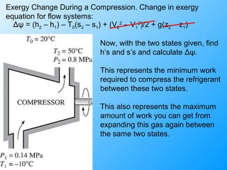

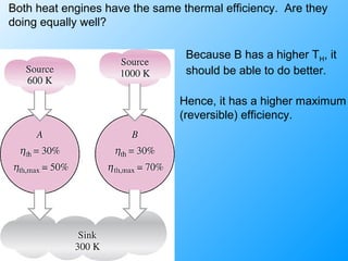
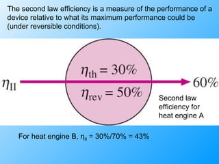
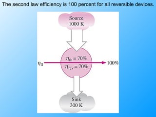
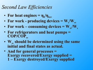
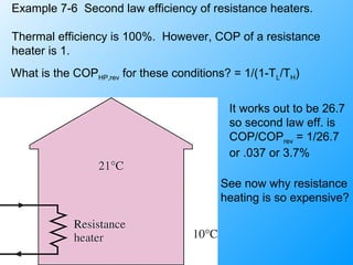
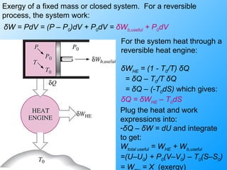
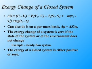
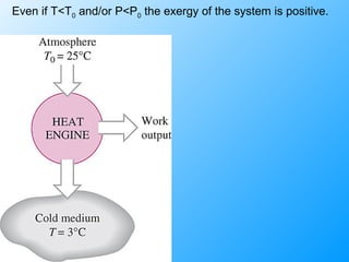
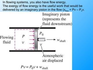
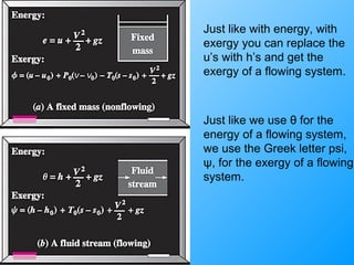
The document discusses second law efficiencies and exergy change of systems. It defines second law efficiency for various devices like heat engines, work-producing devices, refrigerators, and general processes. Second law efficiency compares the actual performance of a device to its theoretical maximum performance under reversible conditions. The exergy change of a closed system depends on the change in internal energy, pressure-volume work, and entropy between initial and final states, accounting for environmental properties. Exergy can represent the useful or recoverable work of a system.


