This document discusses reversible work, irreversibility, and availability in thermodynamics. It defines reversible work as the maximum possible work for a process, calculated by assuming the process is reversible with no entropy production. Irreversibility is defined as the difference between reversible and actual work. Availability is the maximum reversible work that can be extracted from a system as it moves to equilibrium with its surroundings. The document provides equations for calculating reversible work, irreversibility, and availability. It also introduces exergy as a measure analogous to availability. Several examples apply these concepts to problems involving turbines, compressors, and nozzles.
![where Wa is the actual work and Wrev is the reversible work for the fictitious reversible process. Second-
law efficiency is different from the adiabatic efficiency of a device introduced in Chap. 6. It is generally
higher and provides a better comparison to the ideal.
Second, irreversibility is defined as the difference between the reversible work and the actual work for
a process, or
I = Wrev − Wa ð7:3Þ
On a per-unit-mass basis,
i = wrev − wa ð7:4Þ
Both irreversibility and second-law efficiency will allow us to consider how close an actual process or
device is to the ideal. Once the irreversibilities for devices in an actual engineering system, such as a
steam power cycle, have been calculated, attempts to improve the performance of the system can be
guided by attacking the largest irreversibilities. Similarly, since the maximum possible work will be
reversible work, irreversibility can be used to evaluate the feasibility of a device. If the irreversibility
of a proposed device is less than zero, the device is not feasible. [Section 7.2 develops the concepts of
reversible work and irreversibility.]
Availability is defined as the maximum amount of reversible work that can be extracted from a
system:
É = ðWrevÞmax ð7:5Þ
or, on a per-unit-mass basis,
= ðwrevÞmax ð7:6Þ
The maximization in (7.5) and (7.6) is over the reversible path joining the prescribed initial state to a final
dead state in which system and surroundings are in equilibrium. [Section 7.3 develops the notion of
availability.]
7.2 REVERSIBLE WORK AND IRREVERSIBILITY
To obtain expressions for reversible work and irreversibility, we will consider a transient process
with specified work output and heat input and a uniform through-flow. We begin by allowing this to be
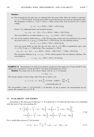
an irreversible process. Consider the control volume shown in Fig. 7-1. The first law for this control
volume can be written as
_Q − _WS = h2 +
V 2
2
2
+ gz2
!
_m2 − h1 +
V 2
1
2
+ gz1
!
_m1 + _Ec:v: ð7:7Þ
Using (6.47), with Tsurr = T0 and _Qsurr = − _Q, we may write the second law as
_Sc:v: + s2 _m2 − s1 _m1 −
_Q
T0
− _Sprod = 0 ð7:8Þ
Eliminate _Q between (7.7) and (7.8) to obtain
_WS = − _Ec:v: + T0
_Sc:v: − h2 +
V 2
2
2
+ gz2 − T0s2
!
_m2
+ h1 +
V 2
1
2
+ gz1 − T0s1
!
_m1 − T0
_Sprod
ð7:9Þ
162 REVERSIBLE WORK, IRREVERSIBILITY, AND AVAILABILITY [CHAP. 7](https://image.slidesharecdn.com/pottermerleccapitulo8-181128201225/85/Potter-merle-c-capitulo-8-1-320.jpg)
![Since _Sprod is due to the irreversibilities, the reversible work rate is given by (7.9) when _Sprod is set equal to zero:
_Wrev = − _Ec:v: + T0
_Sc:v: − h2 +
V 2
2
2
+ gz2 − T0s2
!
_m2 + h1 +
V 2
1
2
+ gz1 − T0s1
!
_m1 ð7:10Þ
Then a time integration yields
Wrev = mi ui +
V 2
i
2
+ gzi − T0si
!
− mf uf +
V 2
f
2
+ gzf − T0sf
!" #
c:v:
:
+ m1 h1 +
V 2
1
2
+ gz1 − T0s1
!
− m2 h2 +
V 2
2
2
+ gz2 − T0s2
! ð7:11Þ
where the subscripts i and f pertain to the initial and final states of the control volume.
The actual work, if not given, can be determined from a first-law analysis:
Wa = mi ui +
V 2
i
2
+ gzi
!
− mf uf +
V 2
f
2
+ gzf
!" #
c:v:
+ m1 h1 +
V 2
1
2
+ gz1
!
− m2 h2 +
V 2
2
2
+ gz2
!
+ Q
ð7:12Þ
From (7.3), (7.11), and (7.12),
I = ðmf T0sf − miT0siÞc:v: + T0m2s2 − T0m1s1 − Q ð7:13Þ
For a steady flow with negligible changes in kinetic and potential energies, we have
_Wrev = _m½h1 − h2 + T0ðs2 − s1ÞŠ ð7:14Þ
_I = _mT0ðs2 − s1Þ + _Q ð7:15Þ
It is important to realize that the basic results of this Section—(7.11), (7.12), and (7.13)—also hold
for a system, which is nothing other than a control volume for which m1 = m2 = 0 (and thus
mi = mf = m). Because time plays no part in the thermodynamics of a system, we generally replace
the indices i and f by 1 and 2.
EXAMPLE 7.1 An ideal steam turbine is supplied with steam at 12 MPa and 700
C, and exhausts at 0.6 MPa.
(a) Determine the reversible work and irreversibility.
(b) If the turbine has an adiabatic efficiency of 0.88, what is the reversible work, irreversibility, and second-law
efficiency?
CHAP. 7] REVERSIBLE WORK, IRREVERSIBILITY, AND AVAILABILITY 163
Fig. 7-1 The control volume used in the second-law analysis.](https://image.slidesharecdn.com/pottermerleccapitulo8-181128201225/85/Potter-merle-c-capitulo-8-2-320.jpg)
![In carrying out a second-law analysis, it is often useful to define a new thermodynamic function
(analogous to enthalpy), called exergy:
E h +
V 2
2
+ gz − T0s ð7:18Þ
Comparing (7.18) to (7.17), we see that E1 − E0 = . We interpret this equation as a work-energy
relation: the extractable specific work exactly equals the decrease in useful exergy E between the
entrance and dead states of the system. More generally, when the system passes from one state to
another, specific work in the amount −ÁE is made available.
Certain engineering devices have useful outputs or inputs that are not in the form of work; a nozzle
is an example. Consequently, we generalize the notion of second-law efficiency to that of second-law
effectiveness:
II =
ðavailability producedÞ + ðwork producedÞ + ðadjusted heat producedÞ
ðavailability suppliedÞ + ðwork usedÞ + ðadjusted heat usedÞ
ð7:19Þ
Heat to or from a device is ‘‘adjusted’’ in (7.19) on the basis of the temperature −Th:r: of the heat
reservoir which is interacting with the device:
adjusted heat = 1 −
T0
Th:r:
Q ð7:20Þ
EXAMPLE 7.3 Which system can do more useful work, 0.1 lbm of CO2 at 440
F and 30 psia or 0.1 lbm of N2
at 440
F and 30 psia?
Solution: Assuming a dead state at 77
F (537
R) and 14.7 psia, we use Table E-4E to calculate the
availability of the CO2:
É = m h − h0 − T0 s
1 − s
0 − R ln
P
P0
!
=
0:1
44
7597:6 − 4030:2 − 537 56:070 − 51:032 − 1:986 ln
30
14:7
!
= 3:77 Btu
Similarly, for the N2,
É = m h − h0 − T0 so
1 − so
0 − R ln
P
P0
!
=
0:1
28
6268:1 − 3279:5 − ð537Þ 49:352 − 45:743 − 1:986 ln
30
14:7
!
= 6:47 Btu
Hence, the N2 can do more useful work.
EXAMPLE 7.4 How much useful work is wasted in the condenser of a power plant which takes in steam of
quality 0.85 and 5 kPa and delivers saturated liquid at the same pressure?
Solution: The maximum specific work available at the condenser inlet is 1 = h1 − h0 − T0ðs1 − s0Þ; at
the outlet it is 2 = h2 − h0 − T0ðs2 − s0Þ. The useful work wasted is 1 − 2 = h1 − h2 − T0ðs1 − s2Þ.
From the steam tables, assuming T0 = 298 K and using the quality to find h1 and s1, we find
1 − 2 = h1 − h2 − T0ðs1 − s2Þ = 2197:2 − 136:5 − ð298Þð7:2136 − 0:4717Þ = 51:6 kJ=kg
CHAP. 7] REVERSIBLE WORK, IRREVERSIBILITY, AND AVAILABILITY 165](https://image.slidesharecdn.com/pottermerleccapitulo8-181128201225/85/Potter-merle-c-capitulo-8-4-320.jpg)
![Comparing to sf and sg at 0.1 MPa, we have a two-phase mixture at state 2 with
x2 =
s2 − sf
sfg
= 0:96
so that h2 = hf + 0:96hfg = 2587:3 kJ/kg.
2 ! 3 Ideal turbine: s3 = s2 = 7:1237 kJ=kgÁK
Comparing to sf and sg at 0.01 MPa, we have a two-phase mixture at state 3 with
x3 =
s3 − sf
sfg
= 0:86
so that h3 = hf + 0:86hfg = 2256:9 kJ=kg. The second-law effectiveness is given by
II =
É2 + Wturb
É4 + Wpump + ½1 − ðT0=T1ÞŠQboil
The dead state for water is liquid at 100 kPa and 25
C:
h0 = hf = 104:9 kJ=kg s0 = sf = 0:3672 kJ=kgÁK
Now the various quantities of interest may be calculated, assuming m1 = 1 kg:
É2 = m2½h2 − h0 − T0ðs2 − s0ÞŠ = ð0:1Þ½2587:3 − 104:9 − ð298Þð7:1237 − 0:3672ÞŠ = 46:89 kJ
Wturb = m1ðh1 − h2Þ + m3ðh2 − h3Þ = ð1:0Þð3051:2 − 2587:3Þ + ð0:9Þð2587:3 − 2256:9Þ = 761:3 kJ
É4 = m4½h4 − h0 − T0ðs4 − s0ÞŠ = ð0:1Þ½191:8 − 104:9 − ð298Þð0:6491 − 0:3671ÞŠ = 0:28 kJ
Wpump = m1
ÁP
= ð1:0Þ
1000 − 10
1000
= 0:99 kJ Qboil = m1ðh1 − h6Þ = ð1:0Þð3051:2 − 192:8Þ = 2858 kJ
whence
II =
46:89 + 761:3
0:28 + 0:99 + ð1 − 298=573Þð2858Þ
= 0:59
CHAP. 7] REVERSIBLE WORK, IRREVERSIBILITY, AND AVAILABILITY 167
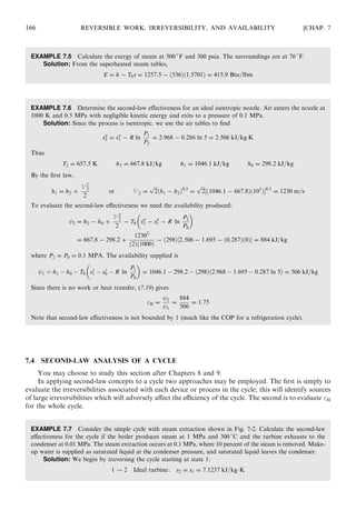
Fig. 7-2](https://image.slidesharecdn.com/pottermerleccapitulo8-181128201225/85/Potter-merle-c-capitulo-8-6-320.jpg)
![and temperature are 0.025 ft3
and 520
R. Determine the reversible work and the irreversibility
associated with the intake process.
At the various states either we are given, or the air tables provide, the values shown in Table 7-2. In the
initial state,
mi =
PiVi
RTi
=
ð13:5Þð144Þð0:0035Þ
ð53:3Þð560Þ
= 2:28 Â 10−4
lbm
The final state is produced by a polytropic process, so that
Pf = Pi
Vi
Vf
n
= ð13:5Þ
0:0035
0:025
−0:04
= 14:6 psia
mf =
Pf Vf
RTf
=
ð14:6Þð144Þð0:025Þ
ð53:3Þð520Þ
= 1:90 Â 10−3
lbm
From conservation of mass, m1 = mf − mi = ð1:90 Â 103
Þ − ð2:28 Â 10 −4
Þ = 1:67 Â 10−3
lbm. Only bound-
ary work is actually performed; for the polytropic process we have
Wa =
Pf Vf − PiVi
1 − n
=
½ð14:6Þð0:025Þ − ð13:5Þð0:0035ÞŠð144Þ
ð1 + 0:04Þð778Þ
= 0:057 Btu
The reversible work is given by (7.11) (neglect KE and PE, as usual):
Wrev = miðui − T0siÞ − mf ðuf − T0sf Þ + m1ðh1 − T0s1Þ
The needed values of si and sf are obtained from the ideal-gas relation
s = s
− R ln
P
P0
where P0 is some reference pressure. Normally, we do not have to worry about P0, since when we consider an
entropy change, P0 cancels. It can be shown that even for this problem it will cancel, so that
Wrev = miðui − T0s
i + T0R ln PiÞ − mf ðuf − T0s
f + T0R ln Pf Þ
+m1ðh1 − T0s
1 + T0R ln P1Þ = 0:058 Btu
and, finally, I = Wrev − Wa = 0:058 − 0:057 = 0:001 Btu.
7.2 A supply pump for a power plant takes in saturated water at 0.01 MPa and boosts its pressure to
10 MPa. The pump has an adiabatic efficiency of 0.90. Calculate the irreversibility and second-
law efficiency.
At the inlet and exit states either we are given, or the steam tables provide, the values given in Table 7-3.
The actual work is
wa =
wideal
= −
ÁP
= −
10 000 − 10
ð0:9Þð1000Þ
= −11:1 kJ=kg
CHAP. 7] REVERSIBLE WORK, IRREVERSIBILITY, AND AVAILABILITY 169
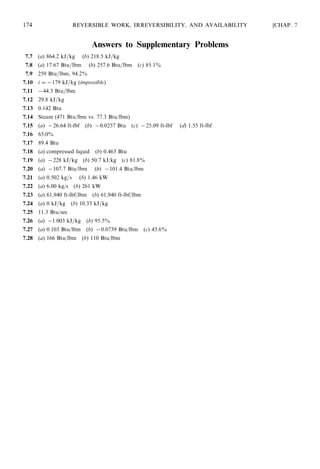
Table 7-2
Inlet State Initial State of C.V. Final State of C.V.
T1 = 520
R Ti = 560
R Tf = 520
R
P1 = 14:7 psia Pi = 13:5 psia uf = 88:62 Btu=lbm
h1 = 124:27 Btu=lbm ui = 95:47 Btu=lbm s
f = 0:5917 Btu=lbm-
R
s
1 = 0:5917 Btu=lbm-
R s
i = 0:6095 Btu=lbm-
R Vf = 0:025 ft3
Vi = 0:0035 ft3](https://image.slidesharecdn.com/pottermerleccapitulo8-181128201225/85/Potter-merle-c-capitulo-8-8-320.jpg)
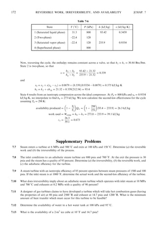
![7.5 A feedwater heater extracts steam from a turbine at 600 kPa and 250
C which it combines with
0.3 kg/s of liquid at 600 kPa and 150
C. The exhaust is saturated liquid at 600 kPa. Determine
the second-law effectiveness of the heater.
For data, see Table 7-5. By conservation of mass, _m3 = _m1 + _m2. Then, the first law demands
_m3h3 = _m1h1 + _m2h2. Solving simultaneously for _m1 and _m3:
_m1 = 0:00504 kg=s _m3 = 0:305 kg=s
The second-law effectiveness is II = _É3=ð _É1 + _É2Þ. Taking the dead state as liquid water at 25
C and
100 kPa, we have
h0 = 105 kJ=kg s0 = 0:3672 kJ=kgÁK
Then
_É3 = _m½h3 − h0 − T0ðs3 − s0ÞŠ = ð0:305Þ½670:6 − 105 − 298ð1:9316 − 0:3672ÞŠ = 30:33 kW
_É1 = _m1½h1 − h0 − T0ðs1 − s0ÞŠ = ð0:00504Þ½2957:2 − 105 − 298ð7:1824 − 0:3672ÞŠ = 4:14 kW
_É2 = _m2½h2 − h0 − T0ðs2 − s0ÞŠ = ð0:30Þ½632:2 − 105 − 298ð1:8422 − 0:3672ÞŠ = 23:63 kW
and
II =
30:33
4:14 + 23:63
= 1:09
7.6 Consider the ideal refrigeration cycle shown in Fig. 7-4 which utilizes R134a. The condenser
operates at 800 kPa while the evaporator operates at 120 kPa. Calculate the second-law effec-
tiveness for the cycle.
The given values and the R134a tables in Appendix D allow us to set up Table 7-6.
CHAP. 7] REVERSIBLE WORK, IRREVERSIBILITY, AND AVAILABILITY 171
Table 7-5
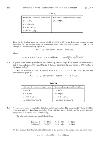
Inlet state 1: superheated vapor Inlet state 2: compressed liquid Exit state 3: saturated liquid
T = 250
C T = 150
C P = 0:6 MPa
P = 0:6 MPa P = 0:6 MPa T = 158:9
C
h = 2957:2 h = 632:2 kJ=kg h = 670:6 kJ=kg
s = 7:1824 kJ=kgÁK s = 1:8422 kJ=kgÁK s = 1:9316 kJ=kgÁK
Fig. 7-4](https://image.slidesharecdn.com/pottermerleccapitulo8-181128201225/85/Potter-merle-c-capitulo-8-10-320.jpg)
![7.14 Ideally, which fluid can do more work: air at 600 psia and 600
F or steam at 600 psia and 600
F?
7.15 A piston-cylinder system with air undergoes a polytropic compression with n = 1:1 from 75
F, 15 psia, and
0.2 liter to 0.04 liter. Determine (a) actual work, (b) heat transfer, (c) reversible work, and (d) irreversibility.
7.16 Methane gas at 800 K and 3 MPa is contained in a piston-cylinder system. The system is allowed to expand
to 0.1 MPa in a polytropic process with n = 2:3. What is the second-law efficiency of the process?
7.17 Argon is contained in a sealed tank of 10 liters at 400 psia and 50
F. What is the maximum work the argon
can do on earth at 536
R?
7.18 A rigid tank initially contains 0.5 lbm of R134a as saturated liquid at 30 psia. It is then allowed to come to
equilibrium with its surroundings at 70
F. Determine (a) the final state of the refrigerant and (b) the
irreversibility.
7.19 Air enters a compressor at 100 kPa and 295 K and exits at 700 kPa and 530 K with 40 kJ=kg of heat transfer
to the surroundings. Determine (a) reversible work, (b) irreversibility, and (c) second-law efficiency for the
compressor.
7.20 A compressor with an adiabatic efficiency of 90 percent intakes air at 500
R and 15 psia and exhausts at 120
psia. Determine (a) the actual work and (b) the reversible work associated with this compressor.
7.21 The evaporator for an air-conditioning system is a heat exchanger. R134a enters at 0.05 kg=s and −20
C as
saturated liquid and leaves as saturated vapor. Air enters at 34
C and leaves at 18
C. (a) What is the mass
flow rate of air? (b) What is the irreversibility rate of the evaporator?
7.22 A direct contact heat exchanger serves as the condenser for a steam power plant. Steam with quality of 50
percent at 100 kPa flows into the mixing tank at 2 kg/s. Groundwater at 10
C and 100 kPa is available to
produce saturated liquid flowing out of the mixing tank. The mixing tank is well-insulated. Determine (a) the
mass flow rate of groundwater required and (b) the irreversibility rate.
7.23 Steam is throttled across an adiabatic valve from 250 psia and 450
F to 60 psia. Determine (a) the reversible
work and (b) the irreversibility.
7.24 It has been proposed to utilize a nozzle in conjunction with a wind turbine system. Air enters the adiabatic
nozzle at 9 m/s, 300 K, and 120 kPa and exits at 100 m/s and 100 kPa. Determine (a) the irreversibility and
(b) the reversible work.
7.25 In the burner for a gas turbine system 0.2 lbm/sec of air at 20 psia and 900
R is heated to 2150
R in a
constant-pressure process while hot combustion gases (assumed to be air) are cooled from 3000
R to
2400
R. What is the irreversibility rate of this process?
7.26 Saturated water enters an adiabatic pump at 10 kPa and exits at 1 MPa. If the pump has an adiabatic
efficiency of 95 percent, determine (a) the reversible work and (b) the second-law efficiency.
7.27 The pressure of water is increased, by the use of a pump, from 14 to 40 psia. A rise in the water temperature
from 60
F to 60.1
F is observed. Determine (a) the irreversibility, (b) the reversible work, and (c) the
adiabatic efficiency of the pump.
7.28 Air at 2200
R and 40 psia enters a gas turbine with an adiabatic efficiency of 75 percent and exhausts at 14.7
psia. Determine (a) the availability of the exhaust air and (b) the reversible work.
CHAP. 7] REVERSIBLE WORK, IRREVERSIBILITY, AND AVAILABILITY 173](https://image.slidesharecdn.com/pottermerleccapitulo8-181128201225/85/Potter-merle-c-capitulo-8-12-320.jpg)
![assuming an ideal gas with constant specific heat. For an isentropic compression between inlet and outlet
we know that
T2 = T1
P2
P1
ðk−1Þ=k
ð8:4Þ
This allows the work to be expressed as, using Cp given in (4.30),
wcomp =
kR
k−1
T1
P2
P1
ðk−1Þ=k
− 1
#
ð8:5Þ
For a polytropic process we simply replace k with n and obtain
wcomp =
nR
n − 1
T1
P2
P1
ðn−1Þ=n
− 1
#
ð8:6Þ
The heat transfer is then found from the first law.
By external cooling, with a water jacket surrounding the compressor, the value of n when compres-
sing air can be reduced to about 1.35. This reduction from 1.4 is difficult since heat transfer must occur
from the rapidly moving air through the compressor casing to the cooling water, or from fins. This is an
ineffective process, and multistage compressors with interstage cooling are often a desirable alternative.
With a single stage and with a high P2 the outlet temperature T2 would be too high even if n could be
reduced to, say, 1.3.
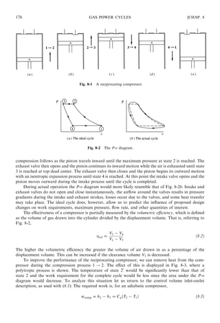
Consider a two-stage compressor with a single intercooler, as shown in Fig. 8-4a. The compression
processes are assumed to be isentropic and are shown in the T-s and P-v diagrams of Fig. 8-4b.
Referring to (8.5), the work is written as
wcomp = CpT1
P2
P1
ðk−1Þ=k
− 1
#
+ CpT3
P4
P3
ðk−1Þ=k
− 1
#
= CpT1
P2
P1
ðk−1Þ=k
+
P4
P2
ðk−1Þ=k
− 2
#
where we have used P2 = P3 and T1 = T3, for an ideal intercooler. To determine the intercooler pressure
P2 that minimizes the work, we let @wcomp=@P2 = 0. This gives
P2 = ðP1P4Þ1=2
or
P2
P1
=
P4
P3
ð8:8Þ
CHAP. 8] GAS POWER CYCLES 177
Fig. 8-3 Removal of heat during compression.
ð8:7Þ](https://image.slidesharecdn.com/pottermerleccapitulo8-181128201225/85/Potter-merle-c-capitulo-8-16-320.jpg)
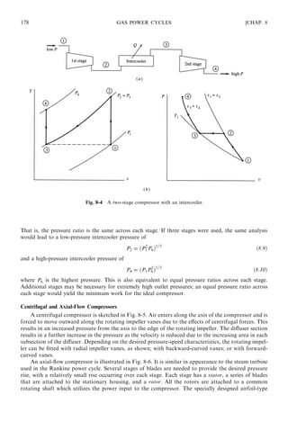
![blades require extreme precision in manufacturing and installation to yield the maximum possible
pressure rise while avoiding flow separation. The area through which the air passes decreases slightly
as the pressure rises due to the increased density in the higher-pressure air. In fluid mechanics the
velocity and pressure at each stage can be analyzed; in thermodynamics we are concerned only with
inlet and outlet conditions.
CHAP. 8] GAS POWER CYCLES 179
Fig. 8-5 A centrifugal compressor.
Fig. 8-6 An axial-flow compressor.](https://image.slidesharecdn.com/pottermerleccapitulo8-181128201225/85/Potter-merle-c-capitulo-8-18-320.jpg)
![The combustion process is replaced by a heat transfer process with energy transferred from an
external source. It may be a constant-volume process or a constant-pressure process, or a
combination.
The exhaust process, used to restore the air to its original state, is replaced with heat transfer to
the surroundings.
All processes are assumed to be in quasiequilibrium.
The air is assumed to be an ideal gas with constant specific heats.
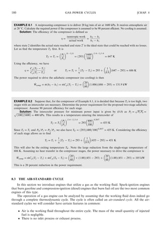
A number of the engines we will consider make use of a closed system with a piston-cylinder
arrangement, as shown in Fig. 8-7. The cycle shown on the P-v and T-s diagrams in the figure is
representative only. The diameter of the piston is called the bore, and the distance the piston travels
in one direction is the stroke. When the piston is at top dead center (TDC), the volume occupied by the
air in the cylinder is at a minimum; this volume is the clearance volume. When the piston moves to
bottom dead center (BDC), the air occupies the maximum volume. The difference between the maximum
volume and the clearance volume is the displacement volume. The clearance volume is often implicitly
presented as the percent clearance c, the ratio of the clearance volume to the displacement volume. The
compression ratio r is defined to be the ratio of the volume occupied by the air at BDC to the volume
occupied by the air at TDC, that is, referring to Fig. 8-7,
r =
V1
V2
ð8:11Þ
The mean effective pressure (MEP) is another quantity that is often used when rating piston-cylinder
engines; it is the pressure that, if acting on the piston during the power stroke, would produce an amount
of work equal to that actually done during the entire cycle. Thus,
Wcycle = ðMEPÞðVBDC − VTDCÞ ð8:12Þ
In Fig. 8-7 this means that the enclosed area of the actual cycle is equal to the area under the MEP
dotted line.
CHAP. 8] GAS POWER CYCLES 181
Fig. 8-7 A piston-cylinder engine.](https://image.slidesharecdn.com/pottermerleccapitulo8-181128201225/85/Potter-merle-c-capitulo-8-20-320.jpg)
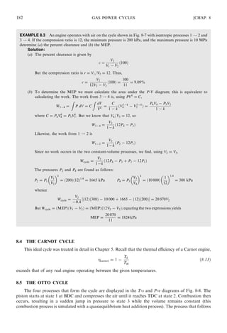
![is the power stroke as the air (simulating the combustion products) expands isentropically to state 4. In
the final process heat transfer to the surroundings occurs and the cycle is completed. The spark-ignition
engine is modeled with this Otto cycle.
The thermal efficiency of the Otto cycle is found from
=
_Wnet
_Qin
=
_Qin − _Qout
_Qin
= 1 −
_Qout
_Qin
ð8:14Þ
Noting that the two heat transfer processes occur during constant-volume processes, for which the work
is zero, there results
_Qin = _mCvðT3 − T2Þ _Qout = _mCvðT4 − T1Þ ð8:15Þ
where we have assumed each quantity to be positive. Then
= 1 −
T4 − T1
T3 − T2
ð8:16Þ
This can be written as
= 1 −
T1
T2
T4=T1 − 1
T3=T2 − 1
ð8:17Þ
For the isentropic processes we have
T2
T1
=
V1
V2
k−1
and
T3
T4
=
V4
V3
k−1
ð8:18Þ
But, using V1 = V4 and V3 = V2, we see that
T2
T1
=
T3
T4
ð8:19Þ
Thus, (8.17) gives the thermal efficiency as
= 1 −
T1
T2
= 1 −
V2
V1
k−1
= 1 −
1
rk−1
ð8:20Þ
CHAP. 8] GAS POWER CYCLES 183
Fig. 8-8 The Otto cycle.](https://image.slidesharecdn.com/pottermerleccapitulo8-181128201225/85/Potter-merle-c-capitulo-8-22-320.jpg)

![[W f stoecker]_refrigeration_and_a_ir_conditioning_(book_zz.org)](https://cdn.slidesharecdn.com/ss_thumbnails/wfstoeckerrefrigerationandairconditioningbookzz-161019162540-thumbnail.jpg?width=640&height=640&fit=bounds)