Downloaded 137 times
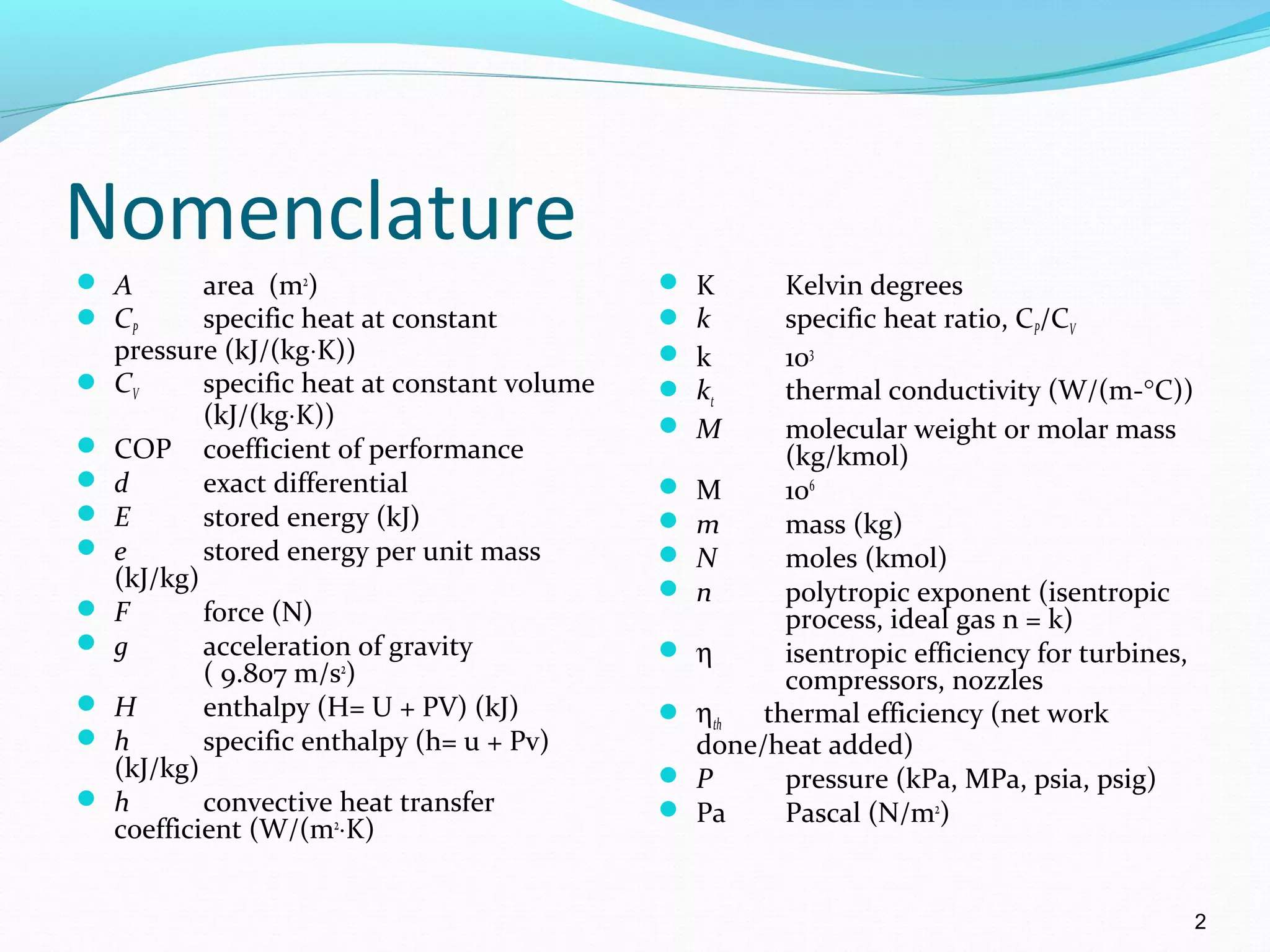
![Nomenclature con’t
Qnet net heat transfer (∑Qin - ∑Qout)
(kJ)
qnet Qnet /m, net heat transfer per
unit mass (kJ/kg)
R particular gas constant
(kJ/(kg⋅K))
Ru universal gas constant
(= 8.314 kJ/(kmol⋅K) )
S entropy (kJ/K)
s specific entropy (kJ/(kg⋅K))
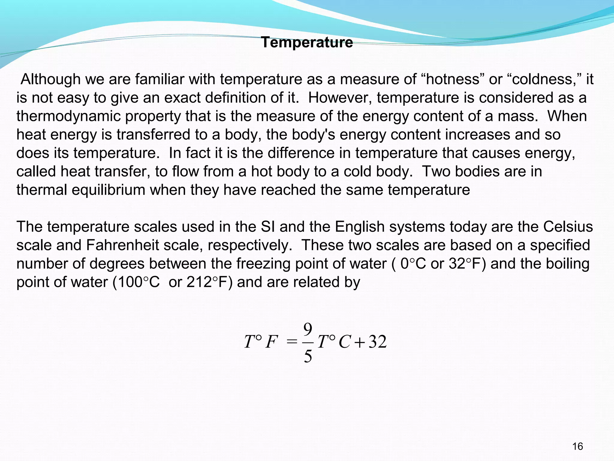
T temperature ( °C, K, °F, R)
U internal energy (kJ)
u specific internal energy
(kJ/(kg ⋅K))
V volume (m3
)
volume flow rate (m3
/s)
velocity (m/s)
specific volume (m3
/kg)
v molar specific volume (m3
/kmol)
X distance (m)
X exergy (kJ)
x quality
Z elevation (m)
Wnet net work done [(∑Wout -
∑Win)other + Wb] (kJ)where Wb =
for closed systems and 0 for
control volumes
wnet Wnet /m, net work done per unit
mass (kJ/kg)
Wt weight (N)
δ inexact differential
ε regenerator effectiveness
ϕ relative humidity
ρ density (kg/m3
)
ω humidity ratio
3
V
V
v](https://image.slidesharecdn.com/basicofthermodynamics-sectiona-161124193354/75/Basic-of-thermodynamics-section-a-3-2048.jpg)


![The Entropy Change of a Pure Substance
The entropy of a pure substance is determined from the tables, just as for any
other property
Pure substances:
Any process: s = s2 - s1 [kJ/(kg-K)]
Isentropic process: s2 = s1
Incompressible substances:
Any process: s2 - s1 = Cav 1n [kJ/(kg-K)]
Isentropic process: T2 = T1
T2
T1](https://image.slidesharecdn.com/basicofthermodynamics-sectiona-161124193354/75/Basic-of-thermodynamics-section-a-89-2048.jpg)


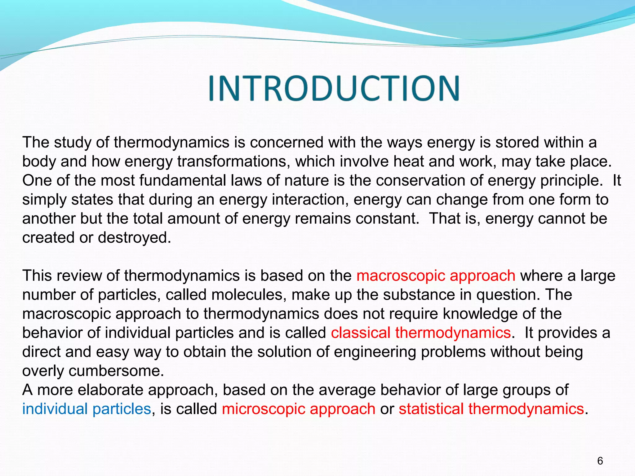
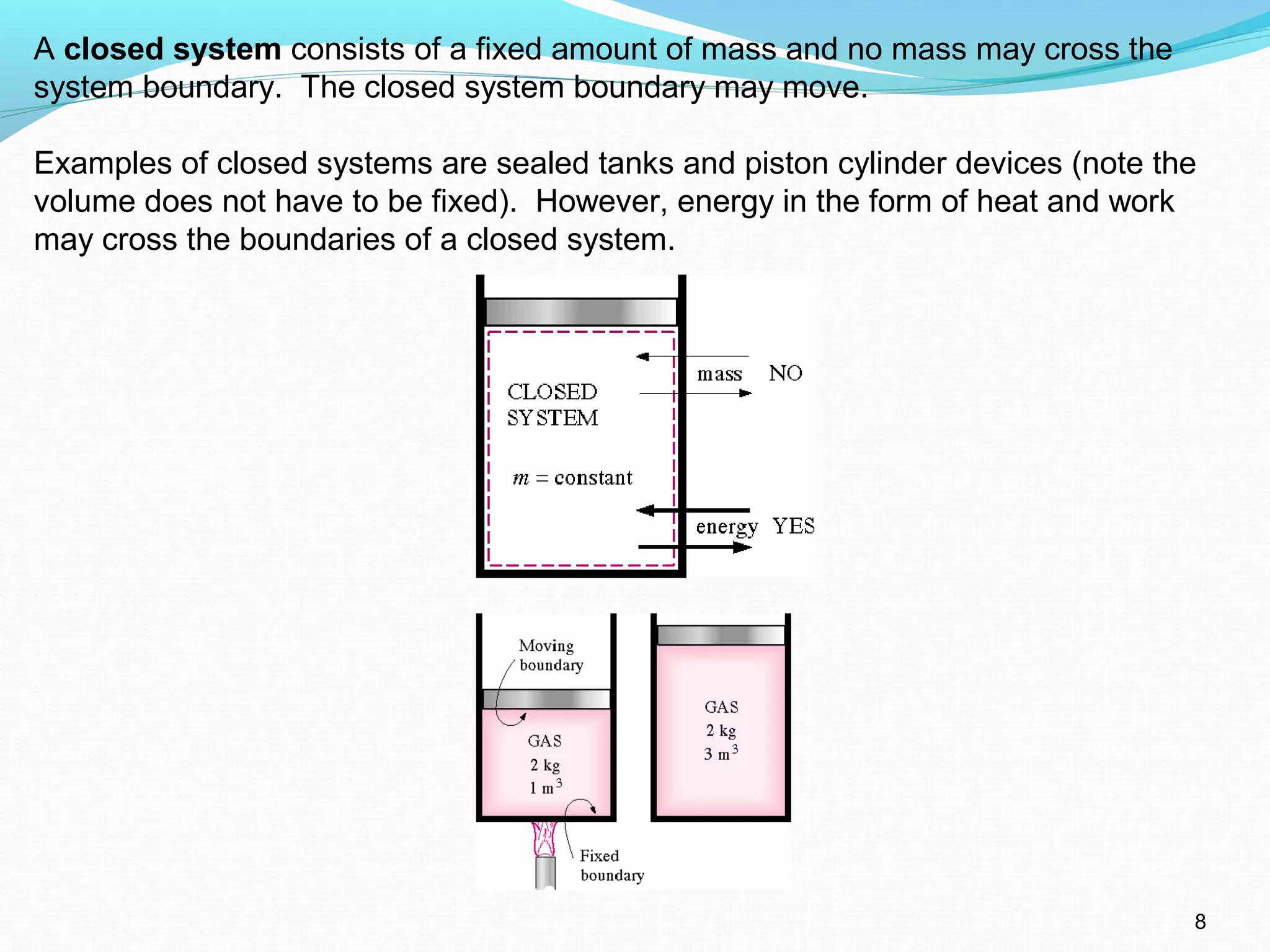
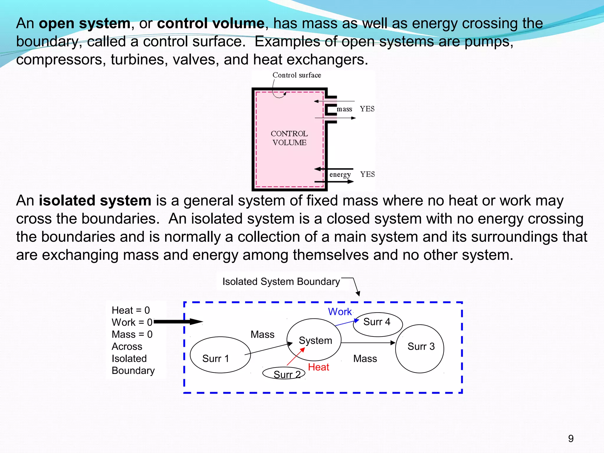
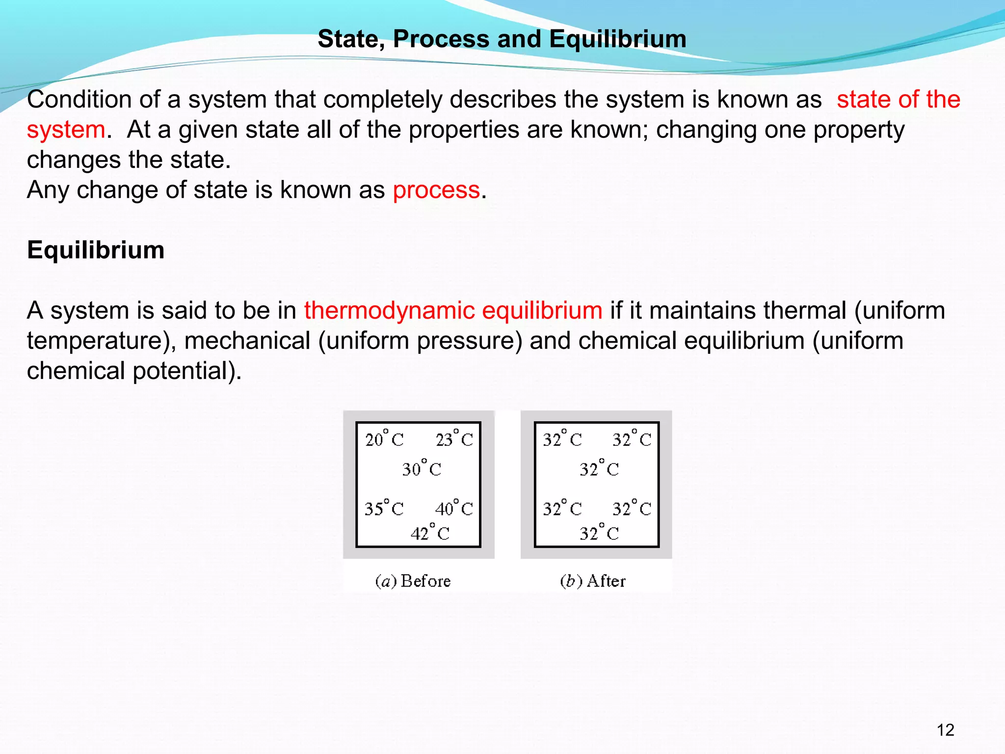
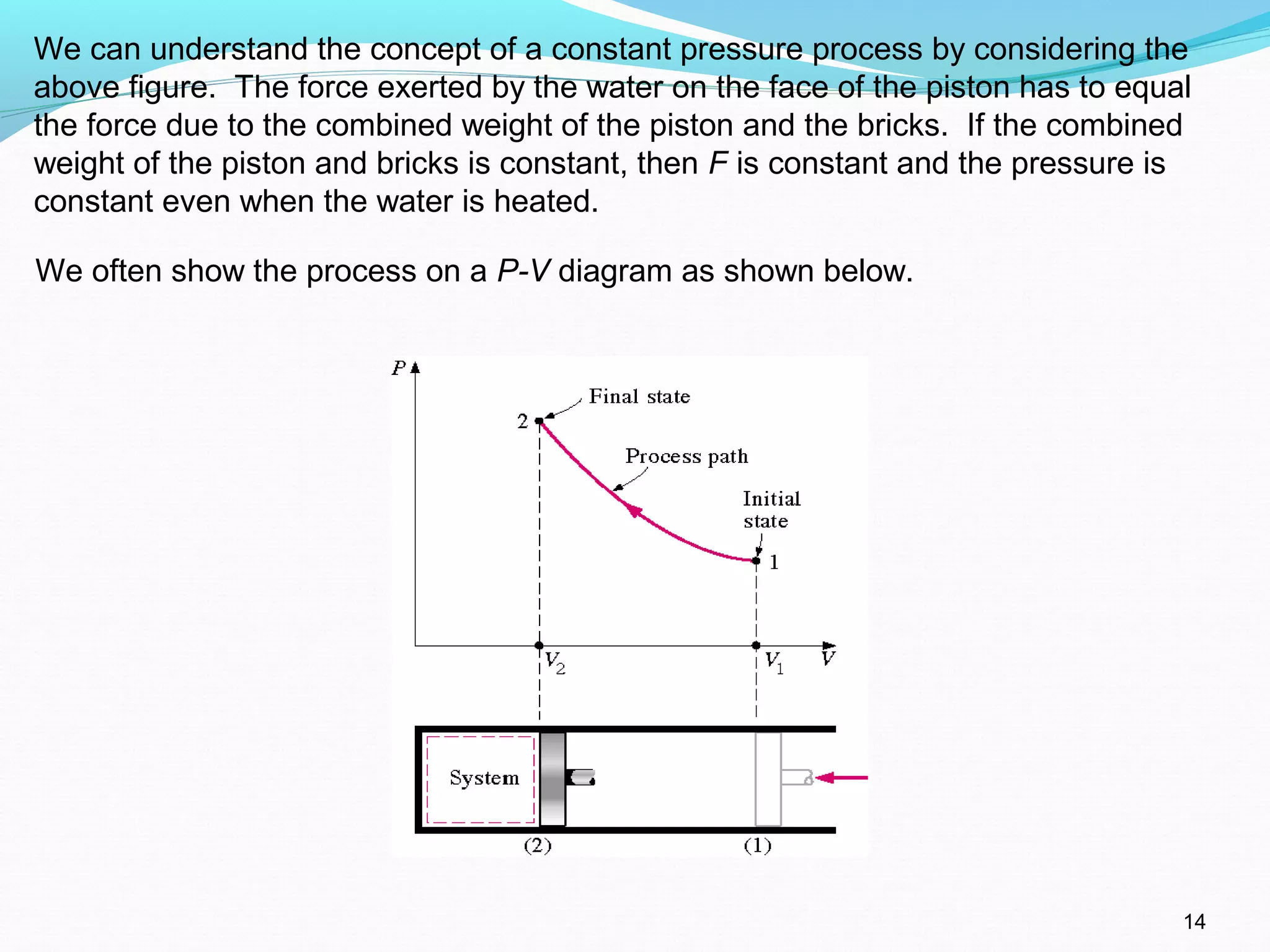
The document is an introductory overview of thermodynamics, detailing key concepts such as energy conservation, system types (closed, open, and isolated), and thermodynamic properties. It describes the macroscopic and microscopic approaches to thermodynamics, the concept of state and processes, and the definitions of temperature using various scales. Additionally, it discusses energy components, including internal, kinetic, and potential energy, as well as heat and work as energy transfer mechanisms.