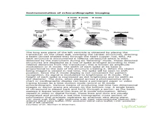
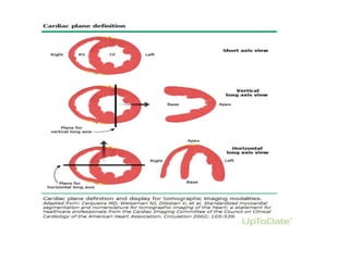
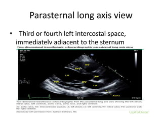
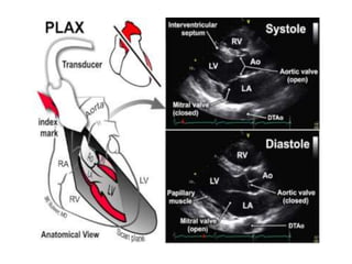
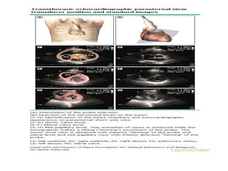
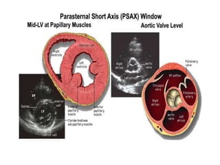
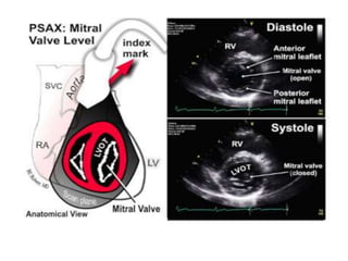
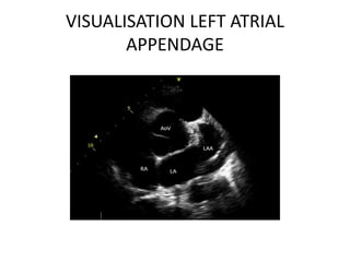
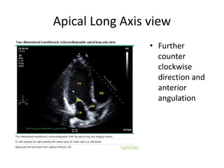
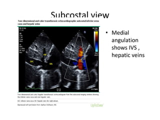
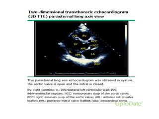
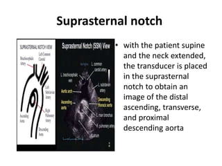
2dEchocardiography
Dr.Sruthi Meenaxshi MBBS,MD,PDF
Ultrasound waves
• Sound waves are mechanical vibrations that
can be described in terms of frequency or
Hertz (Hz), ie, the number of repetitions or
cycles per second.
• Other characteristics include wavelength, the
distance between excitations, measured in
mm; and the amplitude of excitation,
measured in decibels (dB).
• Medical ultrasound imaging typically uses
sound waves at frequencies of 1,000,000 to
20,000,000 Hz (1.0 to 20 MHz).
• In contrast, the human auditory spectrum
comprises frequencies between 20 and 20,000
Hz.
INTERACTION OF ULTRASOUND
WAVES WITH TISSUES
• When ultrasound beam hits the target it can
undergo
• Reflection
• Refraction
• Scattering
• Attenuation – Reduce signal strength
ULTRASOUND TRANSDUCERS
• Ultrasound transducers use piezoelectric crystals to
both generate and receive ultrasound waves
• These crystals (quartz or titanate ceramic) alternately
compress and expand the alternating electric current
that is applied, thereby generating the ultrasound
wave.
• Following a brief period of transmission, typically 1 to
6 microseconds, the same crystal also acts as a
receiver.
• When a reflected ultrasound wave impacts the
piezoelectric crystal, an electric current is generated.
Ultrasound transducer
• 2D image is generated from data obtained
electronically using a phased-array transducer.
• Since each scan line of data requires a finite
period of time for transmission and reception,
the time required to complete each 2D image
is directly related to the number of scan lines.
Tomographic View
• Each tomographic view is defined by the
transducer position
• parasternal
• apical
• subcostal
• suprasternal
Views
• Views obtained by manipulation of transducer
by combined angulation and rotation
• long axis
• short axis
• four-chamber
• five-chamber.
Parasternal long axis view
• Third or fourth left intercostal space,
immediately adjacent to the sternum
Right ventricular inflow and outflow-
PLAX
• Infero medial
angulation of
Parasternal long axis
view
• Visualize IVC, RA ,RV, TV
Parasternal short axis
• From the parasternal long axis orientation, a 70º
to 110º clockwise rotation of the transducer
• superior and inferior transducer manipulations
permits delineation of the parasternal short axis
views
• base (aortic valve)
• basal left ventricular (mitral valve)
• mid-left ventricular (papillary muscle)
• and apical left ventricular levels
PSAX-
Apical level
MERCEDES BENZ SIGN
All three leaflets of the
aortic valve may be
identified, forming a "Y"
configuration during
ventricular diastole, with
the interatrial septum
adjacent to the
noncoronary cusp.
Mitral valve PSAX
FISH MOUTH APPEARANCE
VISUALISATION LEFT ATRIAL
APPENDAGE
ANALYSIS OF WALL MOTION PSAX
• Slight inferior
angulation of PSAX view
helps in assessing wall
motion abnormalities in
Myocardial infarction
patients
Apical 4 chamber view
• Transducer at
apex
• Visualize all 4
chambers
Apical five-chamber
• Anterior angulation and
slight clockwise rotation
of the transducer .
• permits imaging of the
left ventricular outflow
tract, right and left
leaflets of the aortic
valve, and proximal
ascending aorta
Apical two-chamber
• Counter
clockwise
direction from
apical 4
chamber view
reveals 2
chamber view
Apical Long Axis view
• Further
counter
clockwise
direction and
anterior
angulation
Subcostal view
• obtained with the patient
supine in full inspiration
to bring the heart closer
to the imaging probe and
with the knees bent to
relax the abdominal
musculature
• The transducer is
positioned immediately
below or to the right of
the xiphoid process.
Subcostal view
• Medial
angulation
shows IVS ,
hepatic veins
Visualisation of aorta subcostal view
• Sliding
transducer to
left visualizes
aorta
Suprasternal notch
• with the patient supine
and the neck extended,
the transducer is placed
in the suprasternal
notch to obtain an
image of the distal
ascending, transverse,
and proximal
descending aorta
thankyou

2 d echocardiography views

  • 1.
  • 2.
    Ultrasound waves • Soundwaves are mechanical vibrations that can be described in terms of frequency or Hertz (Hz), ie, the number of repetitions or cycles per second. • Other characteristics include wavelength, the distance between excitations, measured in mm; and the amplitude of excitation, measured in decibels (dB).
  • 4.
    • Medical ultrasoundimaging typically uses sound waves at frequencies of 1,000,000 to 20,000,000 Hz (1.0 to 20 MHz). • In contrast, the human auditory spectrum comprises frequencies between 20 and 20,000 Hz.
  • 5.
    INTERACTION OF ULTRASOUND WAVESWITH TISSUES • When ultrasound beam hits the target it can undergo • Reflection • Refraction • Scattering • Attenuation – Reduce signal strength
  • 6.
    ULTRASOUND TRANSDUCERS • Ultrasoundtransducers use piezoelectric crystals to both generate and receive ultrasound waves • These crystals (quartz or titanate ceramic) alternately compress and expand the alternating electric current that is applied, thereby generating the ultrasound wave. • Following a brief period of transmission, typically 1 to 6 microseconds, the same crystal also acts as a receiver. • When a reflected ultrasound wave impacts the piezoelectric crystal, an electric current is generated.
  • 7.
  • 10.
    • 2D imageis generated from data obtained electronically using a phased-array transducer. • Since each scan line of data requires a finite period of time for transmission and reception, the time required to complete each 2D image is directly related to the number of scan lines.
  • 11.
    Tomographic View • Eachtomographic view is defined by the transducer position • parasternal • apical • subcostal • suprasternal
  • 12.
    Views • Views obtainedby manipulation of transducer by combined angulation and rotation • long axis • short axis • four-chamber • five-chamber.
  • 14.
    Parasternal long axisview • Third or fourth left intercostal space, immediately adjacent to the sternum
  • 16.
    Right ventricular inflowand outflow- PLAX • Infero medial angulation of Parasternal long axis view • Visualize IVC, RA ,RV, TV
  • 18.
    Parasternal short axis •From the parasternal long axis orientation, a 70º to 110º clockwise rotation of the transducer • superior and inferior transducer manipulations permits delineation of the parasternal short axis views • base (aortic valve) • basal left ventricular (mitral valve) • mid-left ventricular (papillary muscle) • and apical left ventricular levels
  • 23.
  • 24.
    MERCEDES BENZ SIGN Allthree leaflets of the aortic valve may be identified, forming a "Y" configuration during ventricular diastole, with the interatrial septum adjacent to the noncoronary cusp.
  • 25.
    Mitral valve PSAX FISHMOUTH APPEARANCE
  • 26.
  • 27.
    ANALYSIS OF WALLMOTION PSAX • Slight inferior angulation of PSAX view helps in assessing wall motion abnormalities in Myocardial infarction patients
  • 28.
    Apical 4 chamberview • Transducer at apex • Visualize all 4 chambers
  • 31.
    Apical five-chamber • Anteriorangulation and slight clockwise rotation of the transducer . • permits imaging of the left ventricular outflow tract, right and left leaflets of the aortic valve, and proximal ascending aorta
  • 32.
    Apical two-chamber • Counter clockwise directionfrom apical 4 chamber view reveals 2 chamber view
  • 33.
    Apical Long Axisview • Further counter clockwise direction and anterior angulation
  • 34.
    Subcostal view • obtainedwith the patient supine in full inspiration to bring the heart closer to the imaging probe and with the knees bent to relax the abdominal musculature • The transducer is positioned immediately below or to the right of the xiphoid process.
  • 35.
  • 37.
    Visualisation of aortasubcostal view • Sliding transducer to left visualizes aorta
  • 38.
    Suprasternal notch • withthe patient supine and the neck extended, the transducer is placed in the suprasternal notch to obtain an image of the distal ascending, transverse, and proximal descending aorta
  • 39.