Downloaded 218 times


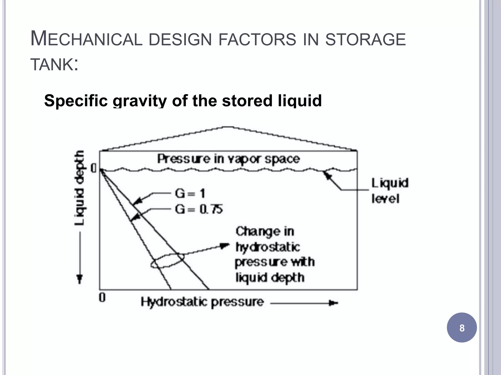


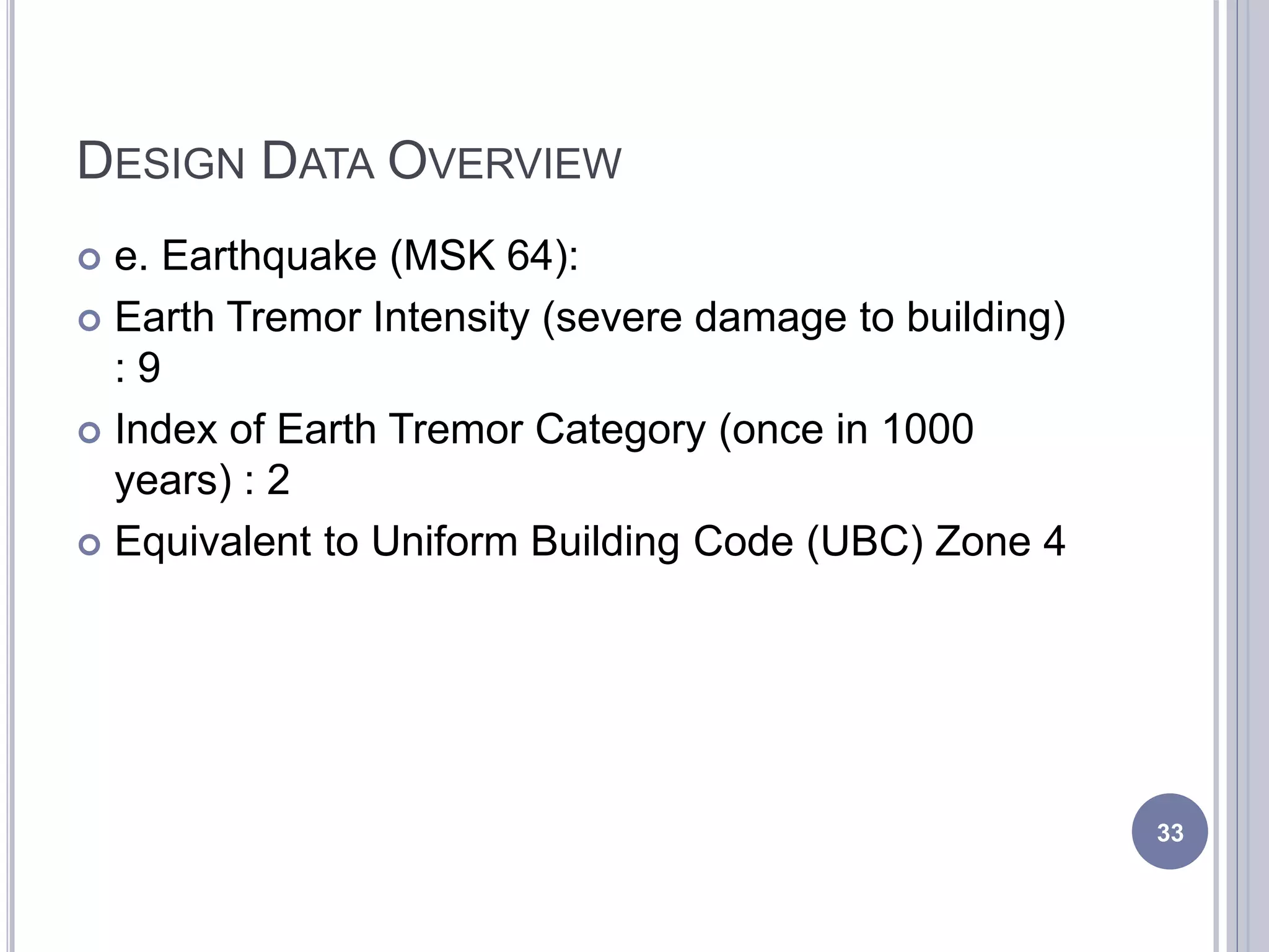

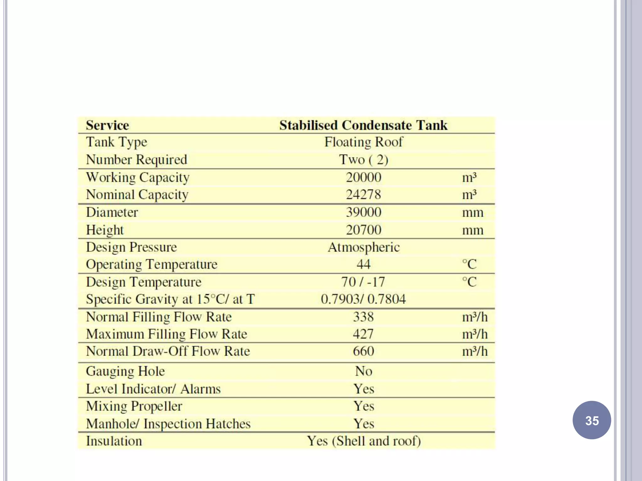
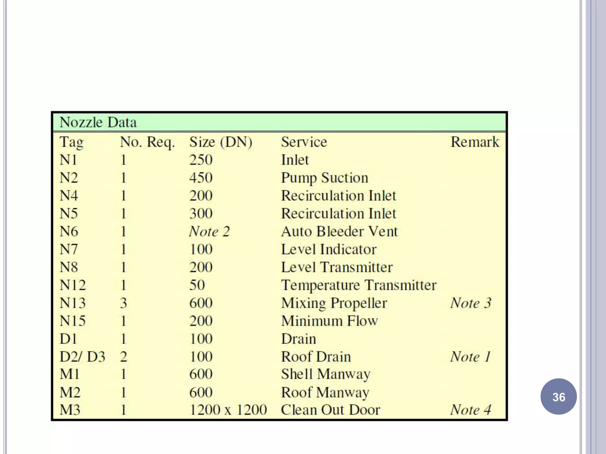

This document outlines the mechanical design requirements and factors for storage tanks. It discusses key considerations like shell thickness determination, temperature effects, pressure, liquid properties, and corrosion allowance. Design codes and standards like API 650 provide guidelines for tank stress analysis and thickness calculations using methods like the 1-foot and variable-design-point approaches. Floating roof tanks are described as having advantages for reducing evaporation but being more complex to design and construct than fixed roof tanks. Design data ranges are also presented for temperature, rainfall, humidity, wind speed, and earthquake conditions.