The paper discusses the Interline Power Flow Controller (IPFC), a flexible AC transmission system device designed to manage power flow across multiple transmission lines simultaneously. It presents a mathematical model to evaluate IPFC's impact on voltage profiles and active/reactive power flow, showing that it can enhance power quality and minimize losses in power systems. Simulation results demonstrate the effectiveness of the IPFC in improving voltage levels and managing power despite disturbances.
![International Journal of Power Electronics and Drive System (IJPEDS)
Vol. 6, No. 3, September 2015, pp. 415~422
ISSN: 2088-8694 415
Journal homepage: http://iaesjournal.com/online/index.php/IJPEDS
Power Quality Enhancement Using the Interline Power Flow
Controller
Abdelkader Benslimane, Chelleli Benachiba
Department of Electrical Engineering, Univercity of Bechar, Algeria
Article Info ABSTRACT
Article history:
Received Nov 24, 2014
Revised Jun 21, 2015
Accepted Jul 19, 2015
Interline power flow controller (IPFC) is one of the latest generation Flexible
AC Transmission system (FACTS). It is able to control simultaneously the
power flow of multiple transmission lines. This paper presents a study of the
impact the IPFC on profile of voltage, real and reactive power flow in
transmission line in power system. The results without and with IPFC are
compared in terms of voltage and active power flows to demonstrate the
performance of the IPFC model.
Keyword:
FACTS
Interline power flow controller
IPFC
Multiple transmission lines
Power quality
Transmission system
Copyright © 2015 Institute of Advanced Engineering and Science.
All rights reserved.
Corresponding Author:
Abdelkader Benslimane
Power quality
Interline Power Flow Controller (IPFC)
Distribution system, FACTs
Email: Kadaslima@yahoo.fr
1. INTRODUCTION
The most powerful and versatile FACTS devices is Interline Power Flow Controller (IPFC). It is
capable to control at the same time the active and reactive power flow in the transmission line. It is a new
member of FACTS controller which is conceived for the compensation and power flow management of
multi-line transmission system [1-4].
Interline Power Flow Controller is one of the latest FACTS controller used to control power flow of
multiple transmission line [5]. The simplest IPFC consists of two back-to-back, dc-to-ac converters namely
Static Synchronous Series Compensators (SSSC), which are connected in series with two transmission lines
through series coupling transformers, and the dc terminals of the converters are connected together via a
common dc link as shown in Figure 1. This paper investigates the performance of IPFC in a power system
network with a detailed mathematical model of IPFC which will be referred as IPFC power injection model
as already presented. This model is helpful in understanding the impact of the IPFC on the power system in
the steady state. Further, the IPFC injection model can easily be incorporated in the steady state power flow
model and the proposed model is used to demonstrate the capabilities of IPFC. This paper shows also that the
IPFC has the possibility of regulating voltage bus, active and reactive power flow, and minimizing the power
losses simultaneously.
2. EQUIVALENT CIRCUIT OF IPFC
In its general form the IPFC employs a number of dc to ac each providing series compensation for a
different line. In other words, the IPFC comprises a number of Static Synchronous Series Compensators](https://image.slidesharecdn.com/0119jul1521jun9apr7075finalarticle2015-171215030016/75/Power-Quality-Enhancement-Using-the-Interline-Power-Flow-Controller-1-2048.jpg)
![ ISSN: 2088-8694
IJPEDS Vol. 6, No. 3, September 2015 : 415 – 422
416
(SSSC) [4]. The IPFC obtained by combing two or more series-connected converters working together
extends the concept of power flow control beyond what is achievable with the known one converter series
FACTS devices –SSSC. A simplest IPFC, with three FACTS buses – i, j and k shown functionally in Figure
1, is used to illustrate the basic operation principle [6-7]. The IPFC consists of two converters being series-
connected with two transmission lines via transformers. It can control three power system quantities -
independent three power flows of the two lines. It can be seen that the sending-ends of the two transmission
lines are series connected with the FACTS buses j and k, respectively.
Figure 1. Equivalent circuit of two converters IPFC
Figure 2. Power injection model of two converters IPFC
An equivalent circuit of the IPFC with two controllable series injected voltage sources is shown in
Figure 2 [8-9]. The real power can be exchanged between or among the series converters via the common DC
link while the sum of the real power exchange should be zero. Suppose in Figure 2, the series transformer
impedance is , and the controllable injected voltage source is ∠ (n = j, k). Active and
reactive power flows of the FACTS branches leaving buses i, j, kare given by:
cos sin (1)
sin cos (2)
sin cos
sin )
(3)
sin
cos
(4)
jQP ijij
jQP ikik
Zseij
Zseik
0ij
dcsese PPEPE ik
Vseij
Vseik
jQP jiji
jQP kiki
Iji
Iki
Vj
Vk
Vi](https://image.slidesharecdn.com/0119jul1521jun9apr7075finalarticle2015-171215030016/75/Power-Quality-Enhancement-Using-the-Interline-Power-Flow-Controller-2-2048.jpg)
![ ISSN: 2088-8694
IJPEDS Vol. 6, No. 3, September 2015 : 415 – 422
418
(14)
Where
is the maximum limit of the power exchange of
series converter with the DC link
∗ ∗
is the current rating of the serie converter
(n=j,k) (15)
3. MODELING OF IPFC IN NEWTON POWER FLOW
Suppose for the IPFC branches i-j, the active and reactive power flows and can be controlled
to power flow control references and by the series converter i-j while for the IPFC branches i-k
only on the active power flow and reactive power flow can be controlled by the series converter i-k, and in
the meantime the active power exchange between the two series converters should be balanced. In addition,
active and reactive power balance at buses i, j, k should also be maintained. Taking into account all these
power flow control constraints and bus power mismatch constraints, the compact form of Newton power flow
equation with incorporation of the IPFC may be written as:
0 0 0 0
0 0 0 0
0 0 0 0
0 0 0 0
0 0 0 0
0 0 0 0
0 0 0 0
∗
∆
∆
∆
∆
∆
∆
∆
∆
∆
∆
∆
∆
∆
∆
∆
∆
(16)
Hence ∆ , ∆ ,∆ ,∆ ,∆ , ∆ are the active and reactive power mismatches at buses i, j, k respectively.
, , , , , are the sum of active and reactive power flows leaving the buses i, j, k respectively. In
this formulation, the terms of the first four rows of the system jacobian matrix correspond to the IPFC power
flow control and active power exchange balance constraints [10].
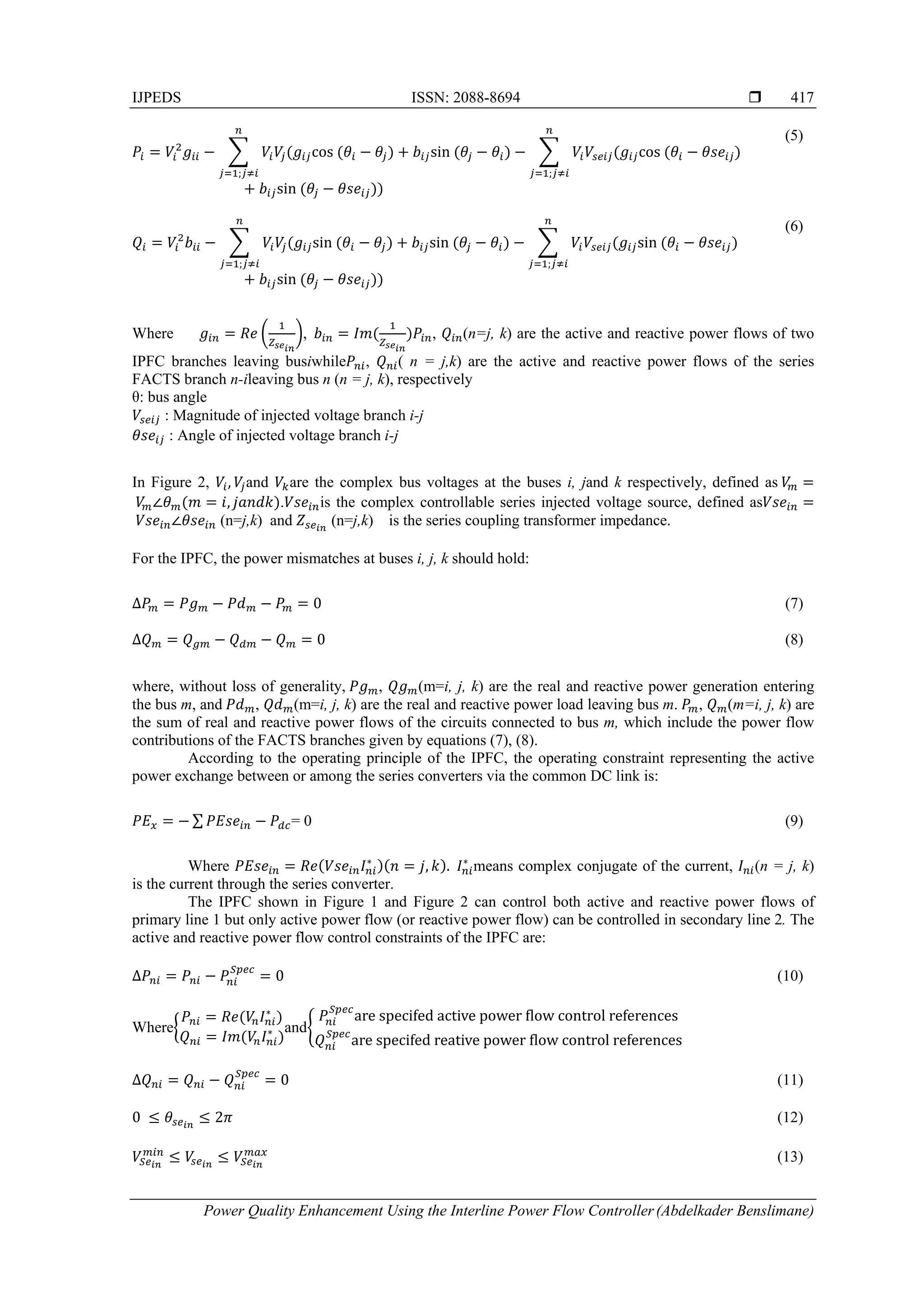
4. SIMULATION RESULTS
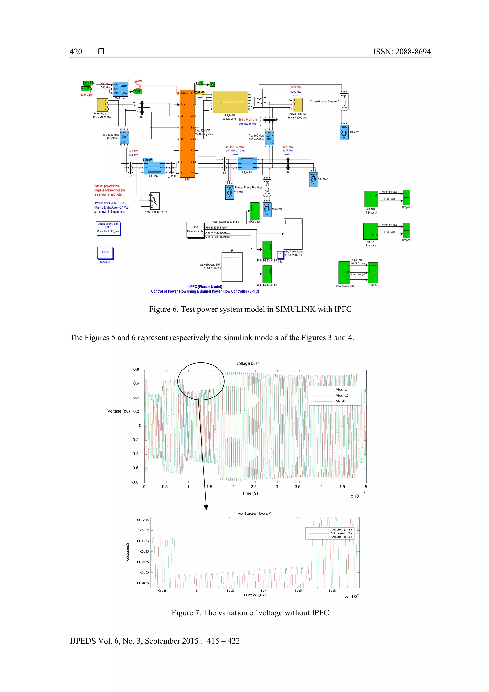
The simulation is done using matlab and the results are presented. Model of 06 nodes (02 nodes
generator) with IPFC is shown in Figure 3. The main objective of this contribution is to evaluate the impact
of the IPFC on the voltage level, and both active and reactive losses. The Figure 4 shows the location of the
IPFC in the network at the bus B4.
.](https://image.slidesharecdn.com/0119jul1521jun9apr7075finalarticle2015-171215030016/75/Power-Quality-Enhancement-Using-the-Interline-Power-Flow-Controller-4-2048.jpg)
![ ISSN: 2088-8694
IJPEDS Vol. 6, No. 3, September 2015 : 415 – 422
422
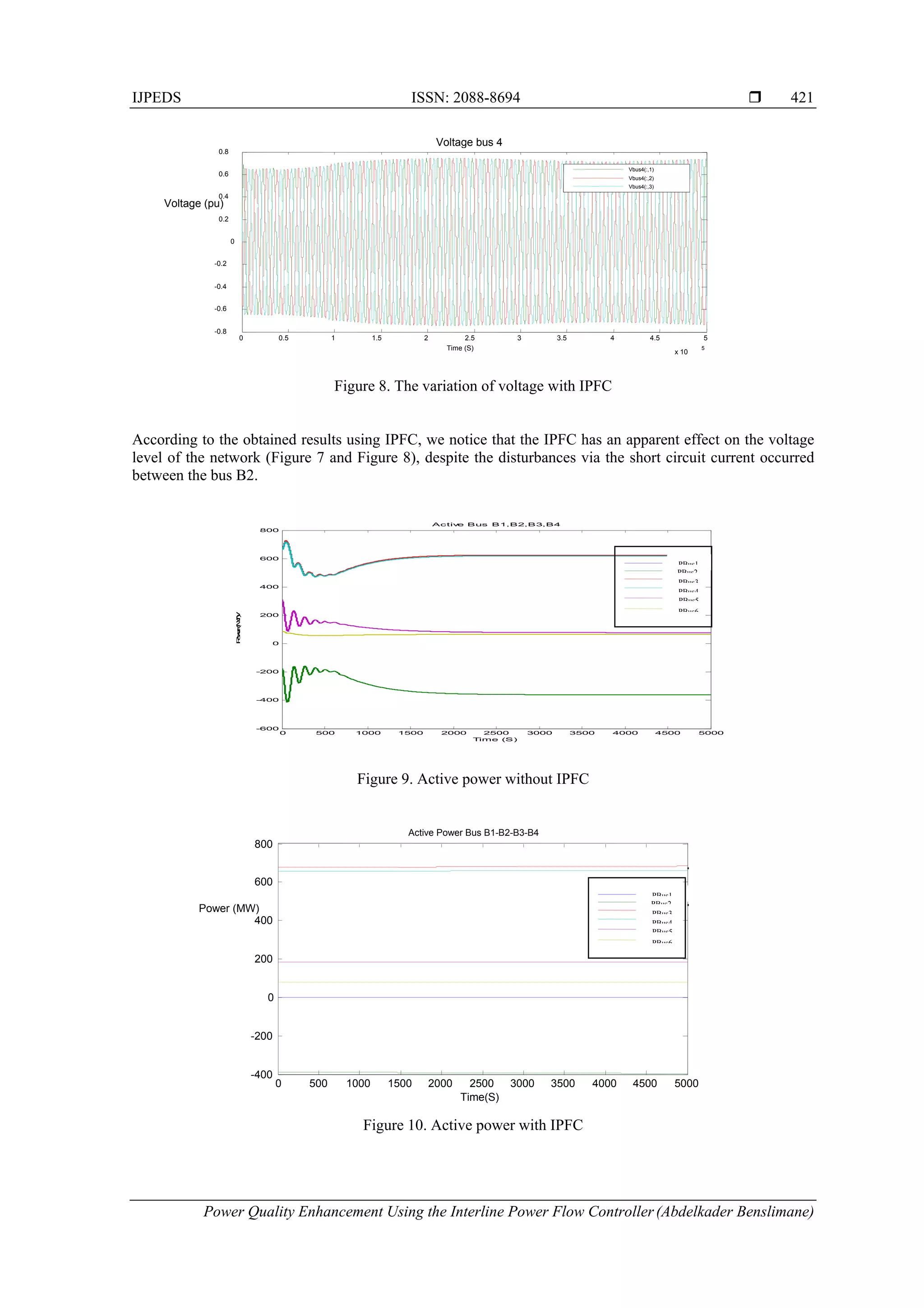
The power flow is maintained constant due to the insertion of the IPFC as is shown respectively on Figure 9
and 10 despite the disturbance.
5. CONCLUSION
The IPFC throughout the obtained has showe that is capable to control the power flow in multiline
systems. It is used to improve the power quality by the imbalance which maintains the level voltage in the
normalized range its action has a positive impact on the both active and reactive losses.
REFERENCES
[1] Indra Prakash Mishra, Sanjiv Kumar, “Control of Active and Reactive Power Flow in Multiple Lines through
Interline Power Flow Controller (IPFC)”, International Journal of Emerging Technology and Advanced
Engineering, ISSN 2250-2459, Volume 2, Issue 11, November 2012 .
[2] A.V. NareshBabu, S. Sivanagaraju, Ch Padmanabharaju and T. Ramana “Multi-Line Power Flow Control using
Interline Power Flow Controller (IPFC) in Power Transmission Systems”, World Academy of Science, Engineering
and Technology, vol 39 2010.
[3] Charan Sekhar, and Ashwani Kumar, "Congestion Management in Hybrid Electricity Markets with FACTS
Devices with Loadability Limits", International Journal of Electrical and Computer Engineering (IJECE), Vol. 2,
No. 1, pp.75-89, 2012.
[4] Prakash Burade and Jagdish Helonde, “Optimal Location of FACTS Device on Enhancing System Security”, in
International Journal of Electrical and Computer Engineering (IJECE), Vol. 2, No. 3, June 2012, pp. 309-316.
[5] Rajshekarsinagham, K. Vijay Kumar, “Role of Inteline Power Flow Controller for Voltage Quality”, IJAEEE
(international journal of advances in electrical and electronic Engineering), Volume 1 Number 2.
[6] X.P. Zhang, “Modelling of the interline power flow controller and the generalized unified power flow controller in
Newton power flow”, IEE proc-GenerTransm Distrib, Volume 150 No 3, May 2003.
[7] VSN Narasimbha Raju B.N.CH.V., Chakravarthi Improvement of Power System Stability Using IPFC and UPFC
Controllers. Volume 3, Issue 2, August 2013.
[8] Xiao-Ping Zhang and Christian Rehtanz “Flexible AC Transmission systems: Modelling and Control”, Sringer –
Verlag Berlin Heidelberg 2012.
[9] P. Mary Jeyaseeli, R. Gabriel Germans, “Impact of IPFC on Distance Protection of Multiline Transmission System,
JIRSET, Volume 3, Issue 3, March 2014.
[10] Yankuizhang, Yan Zhang, and Chen Chen, “A Novel Power Injection Model of IPFC for Power Flow Analysis
Inclusive of Practical Constraints”, IEEE Transation on power systems, Vol. 21, No. 4 November 2006.](https://image.slidesharecdn.com/0119jul1521jun9apr7075finalarticle2015-171215030016/75/Power-Quality-Enhancement-Using-the-Interline-Power-Flow-Controller-8-2048.jpg)


![[IJET-V2I3P17] Authors: R.C.Rohini, G.Srividhya](https://cdn.slidesharecdn.com/ss_thumbnails/ijet-v2i3p17-160711110843-thumbnail.jpg?width=640&height=640&fit=bounds)