
Download to read offline
![REFERENCES
[1] Central Electricity Authority [CEA] (2011) Operation performance of generating stations in the country during
the year 2010-11: An overview, Government of India.
[2] IPCC (2005) IPCC special report on Carbon Dioxide and Storage. Prepared by Working Group III of the
Intergovernmental panel on climate change. Edited by: Metz. B; Davidson. O.; Conick de H.; Loos. M; Meyer. L.
[3] Kohl A, Nielsen R (1997) Gas Purification, 5th edition, Gulf Publishing Company, Houston, Texas.
[4] Aroonwilas, A., and Veawab, A., (2007) Integration of CO2 capture unit using single- and blended- amines into
supercritical coal-fired power plants: Implications for emission and energy management, Int J. Greenhouse Gas
Control, 1, pp. 143-150.
[5] Rao, A.B., and Rubin, E.S., (2002) A Technical, Economics, and Environmental Assessment of Amine-based CO2
capture Technologies for Power Plant Greenhouse Gas Control, Environ. Sci. Technology, 36, pp. 4467-4475.
[6] Zhao, L., Rienche, E., Menzer, R., Blum, L., and Skolten, D., (2008) A parametric study of CO2/N2 gas separation
membrane processes for post-combustion capture, Int J. Membrane Sc., 325, pp. 284-294.
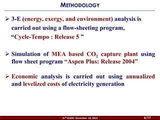
[7] Suresh M.V.J.J. (2012), 4-E (Energy, Exergy, Environment, and Economic) Analysis of Advanced Coal
Technologies for Power Generation, Ph.D. Thesis, Indian Institute of Technology Madras, India.
[8] Merkel, T.C., Zhou, M., and Baker, (2012) Carbon dioxide capture with membranes at an IGCC power plant, Int
J. Membrane Sc., 389, pp. 441-450.
[9] Osikowska, A.S., Szymańska, K.J., and Kotowicz, J., (2012) Modeling and analysis of selected Carbon dioxide
capture methods in IGCC system, Energy, 45, pp. 92-100.
[10] Suresh, M.V.J.J., Reddy, K.S., and Kolar, A.K., (2010) 3-E analysis of advanced power plants based on high
ash coal, Int J. Energy Res., 34, pp. 716-735.
[11] Aspen Plus (2004) Aspen Plus, Aspen technology Inc., Cambridge, MA, USA
[12] Desideri, U., and Paolucci, A., (1999) Performance modeling of a carbon dioxide removal system for power
plants. Energy Convers. Manage., 40, pp. 1899-1915.
[13] Abu-Zahra, M.R.M., Schneiders, L.H.J., Niederer, J.P.M., Feron, P.H.M., and Versteeg, G.F., (2007) CO2 capture
from power plants Part 1. A parametric study of the technical performance based on monoethanolamine. Int. J.
Greenhouse Gas Control, 1, pp. 37-46.
[14] Cycle-Tempo release 5.0 (2007) Delft University of Technology.
[15] Romeo, L.M., Bolea, I., Escosa, J.M., (2008) Integration of power plant and amine scrubbing to reduce CO2
capture costs. Appl. Therm. Eng., 28, pp.1039-1046.
IV th ICAER– December 10, 2013
16/16
16/17](https://image.slidesharecdn.com/175sujit-131211041625-phpapp02/85/175-sujit-16-320.jpg)

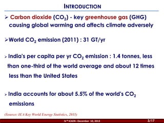
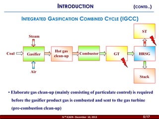
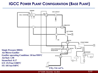
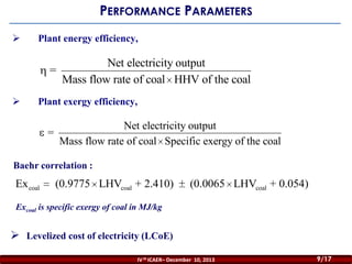
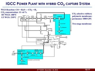
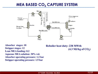
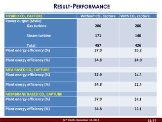
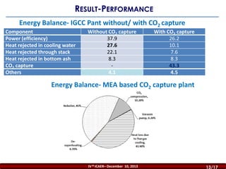
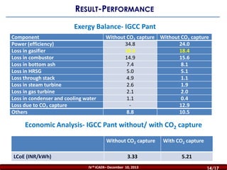
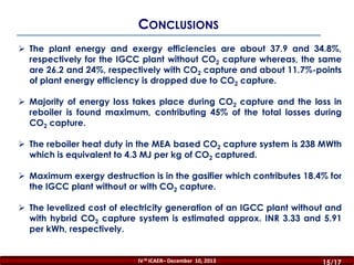
This document presents a techno-economic analysis of an air-blown integrated gasification combined cycle (IGCC) power plant with a hybrid CO2 capture system. The analysis evaluates the plant's performance parameters, including energy and exergy efficiencies, with and without CO2 capture. It finds that CO2 capture reduces the plant's energy efficiency by around 11.7% points. The highest energy losses during CO2 capture occur in the reboiler, which accounts for 45% of total capture losses. The levelized cost of electricity is estimated to increase from INR 3.33/kWh without capture to INR 5.21/kWh with the hybrid capture system.


![Thesis Presentation Template[Conflict 1]](https://cdn.slidesharecdn.com/ss_thumbnails/21bd8c82-0281-470a-b940-684b6bf81c18-150610024222-lva1-app6892-thumbnail.jpg?width=640&height=640&fit=bounds)


![5G Explained! A High Level Overview [Introduction]](https://cdn.slidesharecdn.com/ss_thumbnails/5gexplainedahighleveloverview-260119165306-cc137a3e-thumbnail.jpg?width=640&height=640&fit=bounds)


