


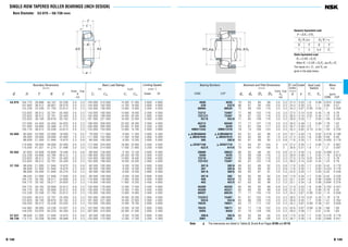
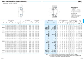
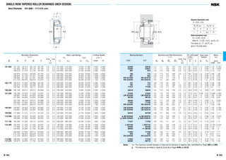
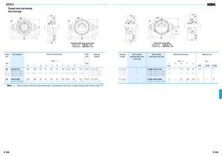
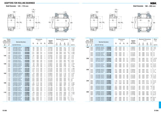
![A 58 A 59
B2
B1
A
C
D
A
C
r (max)×1.2
r (max)×1.2
Stops (at two points)
E
Measuring
Weight
Measuring
Weight
Stops at two points for
inside or outside surface
Supporting pins
at three points around
circumference
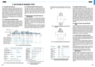
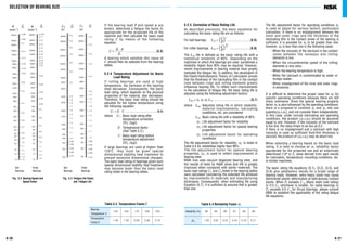
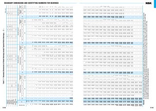
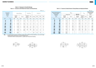
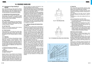
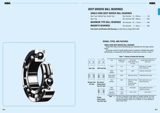
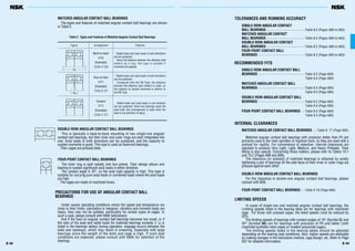
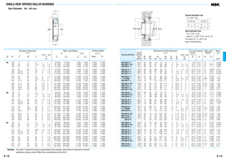
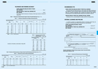
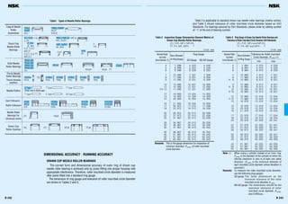
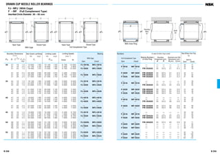
(Reference) Rough definitions of the items listed for
Running Accuracy and their measuring methods are
shown in Fig. 8.1, and they are described in detail in
ISO 5593 (Rolling Bearings-Vocabulary) and JIS B
1515 (Measuring Methods for Rolling Bearings) and
elsewhere.
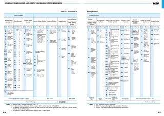
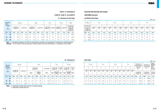
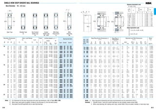
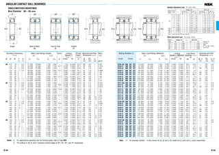
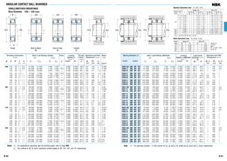
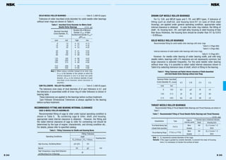
8.1 Bearing Tolerance Standards
The tolerances for the boundary dimensions and
running accuracy of rolling bearings are specified by
ISO 492/199/582 (Accuracies of Rolling Bearings).
Tolerances are specified for the following items:
Regarding bearing accuracy classes, besides ISO
normal accuracy, as the accuracy improves there are
Class 6X (for tapered roller bearings), Class 6, Class
5, Class 4, and Class 2, with Class 2 being the
highest in ISO. The applicable accuracy classes for
each bearing type and the correspondence of these
classes are shown in Table 8.1.
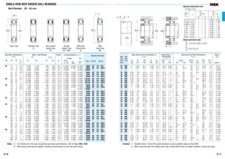
8. BEARING TOLERANCES
Accuracy of Rolling Bearings
( )
Tolerances for Dimensions
⋅ Tolerances for bore and outside diameters, ring width
and bearing width
⋅ Tolerances for inscribed and circumscribed circle
diameters of rollers
⋅ Tolerances for chamfer dimensions
⋅ Tolerances for width variation
⋅ Tolerances for tapered bore diameters
⋅ Permissible radial runout of inner and outer rings
⋅ Permissible face runout with raceway inner and outer
rings
⋅ Permissible inner ring face runout with bore
⋅ Permissible outer ring variation of outside surface
generatrix inclination with face
⋅ Permissible raceway to back face thickness variation of
thrust bearings
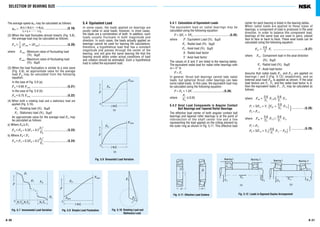
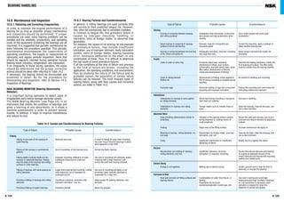
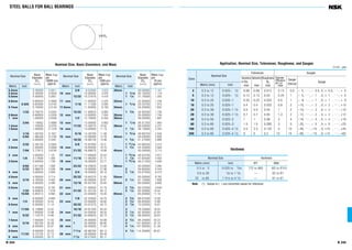
Table 8. 1 Bearing Types and Tolerance Classes
Bearing Types Applicable Tolerance Classes
Applicable Reference
Tables Pages
Deep Groove Ball Bearings Normal Class 6 Class 5 Class 4 Class 2
Angular Contact Ball Bearings Normal Class 6 Class 5 Class 4 Class 2
Self-Aligning Ball Bearings Normal
Class 6 Class 5
Table A60equivalent equivalent
Cylindrical Roller Bearings Normal Class 6 Class 5 Class 4 Class 2
8.2 to A63
Normal Class 6 Class 5 Class 4
Spherical Roller Bearings Normal Class 6 Class 5
Metric Normal Class 5 Class 4 Table A64
Design Class 6X 8.3 to A67
Inch Design ANSI/ABMA ANSI/ABMA ANSI/ABMA ANSI/ABMA ANSI/ABMA Table A68
CLASS 4 CLASS 2 CLASS 3 CLASS 0 CLASS 00 8.4 and A69
Magneto Bearings Normal Class 6 Class 5 Table A70
8.5 and A71
Thrust Ball Bearings Normal Class 6 Class 5 Class 4 Table A72
8.4 to A74
Spherical Thrust Roller Bearings Normal Table A758.7
JIS(1
) Class 0 Class 6 Class 5 Class 4 Class 2
DIN(2
) P0 P6 P5 P4 P2
Ball ABEC 1 ABEC 3 ABEC 5 ABEC 7 ABEC 9 A60
Bearings (CLASS 5P) (CLASS 7P) (CLASS 9P) to A63
ANSI/ Roller RBEC 1 RBEC 3 RBEC 5
(A76
ABMA(3
) Bearings and A77)
Tapered Roller CLASS 4 CLASS 2 CLASS 3 CLASS 0 CLASS 00 (A68
Bearings and A69)
Equivalentstandards
(Reference)
Fig. 8.1 Measuring Methods for Running Accuracy (summarized)
Items necessary to mount
bearings on shafts or in
housings
( )
Running Accuracy
Items necessary to
specify the runout of
rotating machine parts
Tapered
Roller
Bearings
Table
8.2
Table
8.8[ ]
Table
8.4[ ]
Notes (1
) JIS : Japanese Industrial Standards (2
) DIN : Deutsch Industrie Norm
(3
) ANSI/ABMA : The American Bearing Manufacturers Association
Remarks The permissible limit of chamfer dimensions shall conform to Table 8.9 (Page A78), and the tolerances and permissible
tapered bore diameters shall conform to Table 8.10 (Page A80).
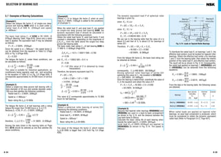
Supplementary Table
Running
Accuracy
Inner
Ring
Outer
Ring
Dial
Gauge
Kia Rotating Stationary A
Kea Stationary Rotating A
Sia Rotating Stationary B1
Sea Stationary Rotating B2
Sd Rotating Stationary C
SD Rotating D
Si , Se E
Only the shaft or housing or
central washer is to be
rotated.
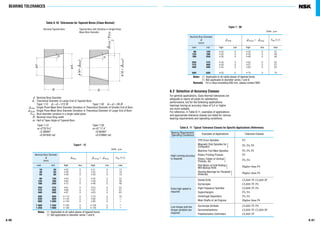
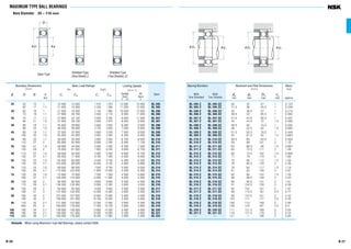
Symbols for Boundary Dimensions and Running Accuracy
d Brg bore dia., nominal
&ds Deviation of a single bore dia.
&dmp Single plane mean bore dia. deviation
Vdp Bore dia. Variation in a single radial plane
Vdmp Mean bore dia. Variation
B Inner ring width, nominal
&Bs Deviation of a single inner ring width
VBs Inner ring width variation
Kia Radial runout of assembles brg inner ring
Sd inner ring reference face (backface, where
applicable) runout with bore
Sia Assembled brg inner ring face (back face)
runout with raceway
Si, Se Raceway to backface thickness variation
of thrust brg
T Brg width, nominal
&Ts Deviation of the actual brg width
D Brg outside dia., nominal
&Ds Deviation of a single outside dia.
&Dmp Single plane mean outside dia. Deviation
VDp Outside dia. Variation in a single radial
plane
VDmp Mean outside dia. Variation
C Outer ring width, nominal
&Cs Deviation of a single outer ring width
VCs Outer ring width variation
Kea Radial runout of assembled brg outer ring
SD Variation of brg outside surface generatrix
inclination with outer ring reference face
(backface)
Sea Assembled brg outer ring face (backface)
runout with raceway
TC
B
jDjd
Needle Roller Bearings
(solid type)](https://image.slidesharecdn.com/nsk-catalogue-140630064240-phpapp01/85/NSK-catalogue-32-320.jpg)


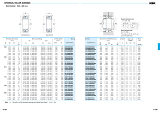


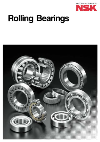
This document is the introduction to NSK's revised rolling bearing catalog (CAT. No. E1102e). It provides an overview of the catalog's contents and structure. The catalog contains general information about rolling bearing types and selection criteria. It also includes extensive tables listing bearing part numbers, dimensions, and design data. The introduction explains that the catalog was revised to reflect new products, standards revisions, and better serve customers' needs for high performance bearings. It aims to help users select the optimal bearing for their application and notes NSK's engineering support is available if needed.