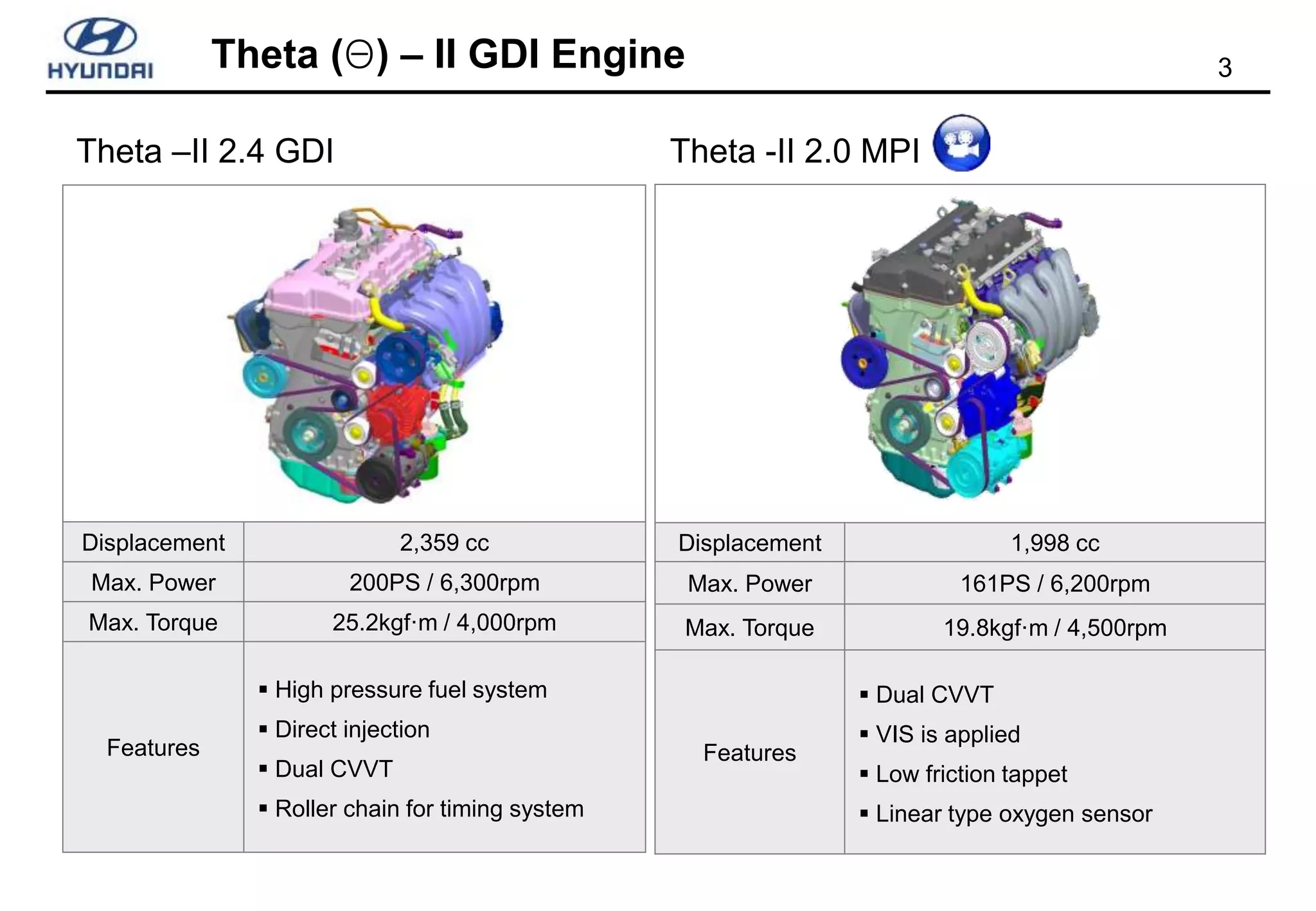
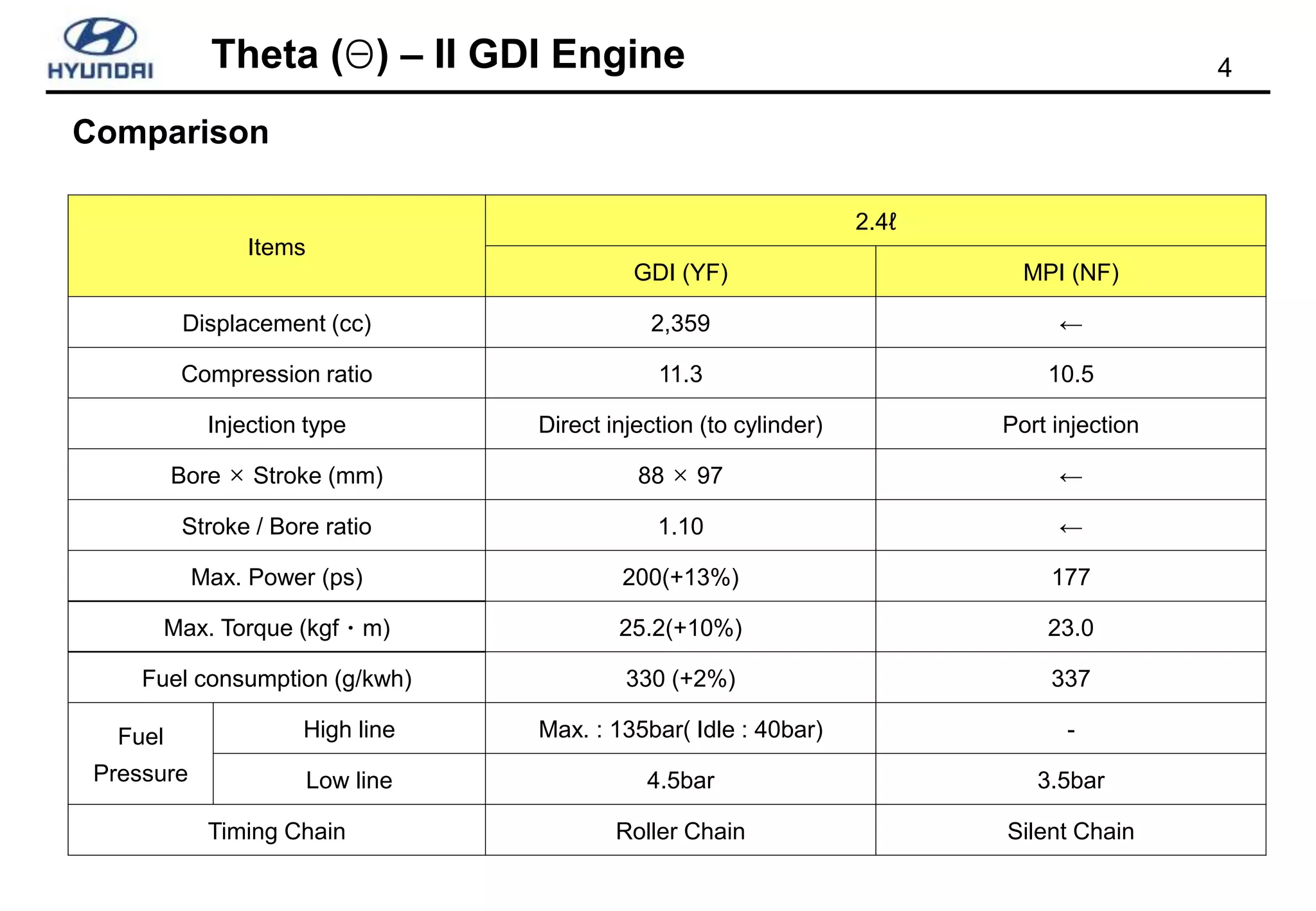
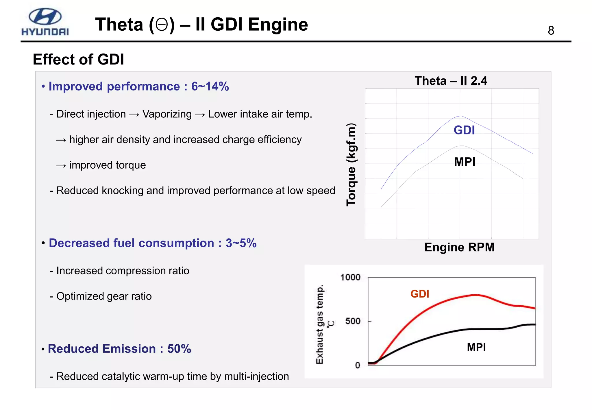
The document summarizes Hyundai's Theta (Θ) - II GDI engine. It describes the key specifications and improvements over the previous MPI engine, including increased power output, torque, and fuel efficiency while decreasing emissions. The main technologies enabling this are direct injection, higher compression ratio, dual CVVT, and multi-injection. The document also provides details on the high pressure fuel system components, such as the high pressure pump, fuel rail, injectors, and pressure sensor.


![10
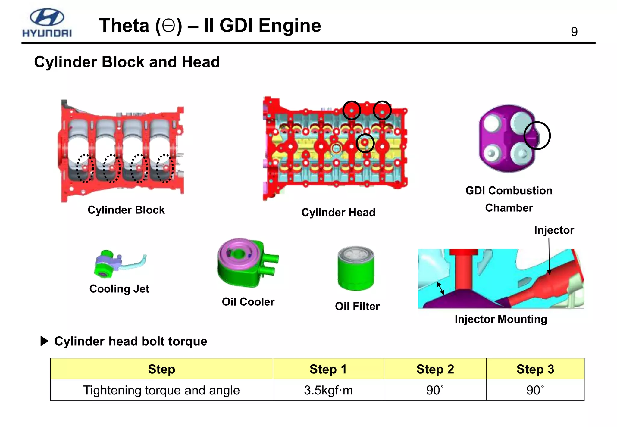
Theta (Θ) – II GDI Engine
[ Camshaft]
Slotted
High pressure pump
driving lobe
• Slotted cam love for reducing weight
• Added cam lobe for high pressure pump
• Fuel pressure is made by camshaft
Camshaft and HP Pump Bracket
HP Pump Bracket Cylinder Head Cover
• Added bracket and hole on cylinder head cover for HP pump](https://image.slidesharecdn.com/321-yfgdiengine20090826-230216040023-48f6c061/75/Hyundai-Theta-II-GDI-Engine-ppt-10-2048.jpg)


![17
Theta (Θ) – II GDI Engine
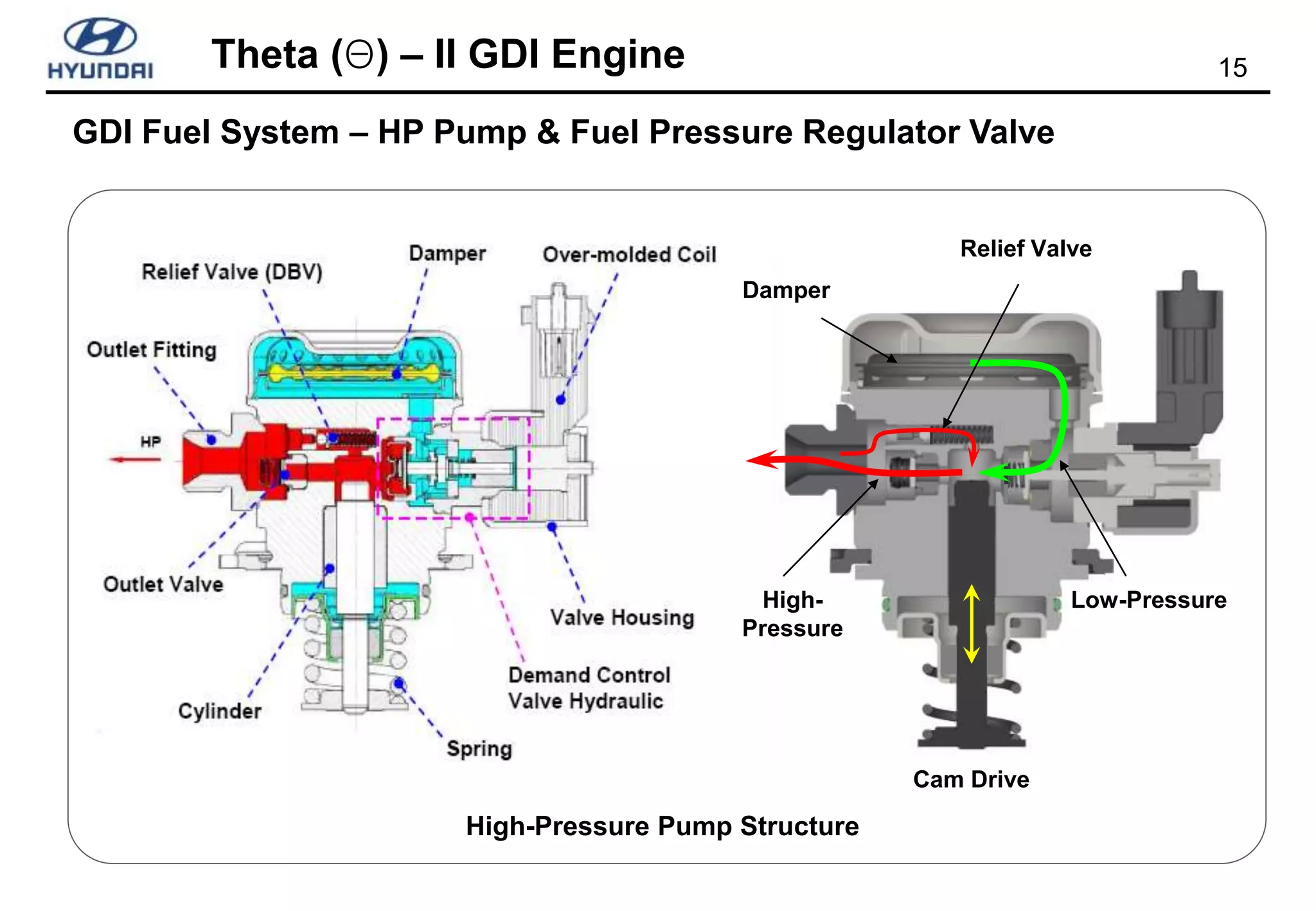
GDI Fuel System – HP Pump & Fuel Pressure Regulator Valve
[ 고압펌프 로브
조립상태 ]
Chamber
Delivery
Chamber
Rail Rail
Fuel Input Fuel Return
Fuel Pressurization
and Discharge Fuel Discharge
Intake Supply
Chamber
Chamber
High-Pressure Pump Mechanism
Voltage
Current](https://image.slidesharecdn.com/321-yfgdiengine20090826-230216040023-48f6c061/75/Hyundai-Theta-II-GDI-Engine-ppt-17-2048.jpg)


![30
Theta (Θ) – II GDI Engine
Evaporation control
Filter
Canister
Throttle
Valve
Cylinder
CCV
PCSV
FTPS
Fuel Tank
P L
Fuel Level Sensor
[ PCSV ]
CCV
PCSV
FTPS](https://image.slidesharecdn.com/321-yfgdiengine20090826-230216040023-48f6c061/75/Hyundai-Theta-II-GDI-Engine-ppt-30-2048.jpg)


![[Volkswagen] manual de_taller_volkswagen_lupo](https://cdn.slidesharecdn.com/ss_thumbnails/volkswagenmanualdetallervolkswagenlupo-191021180259-thumbnail.jpg?width=640&height=640&fit=bounds)


