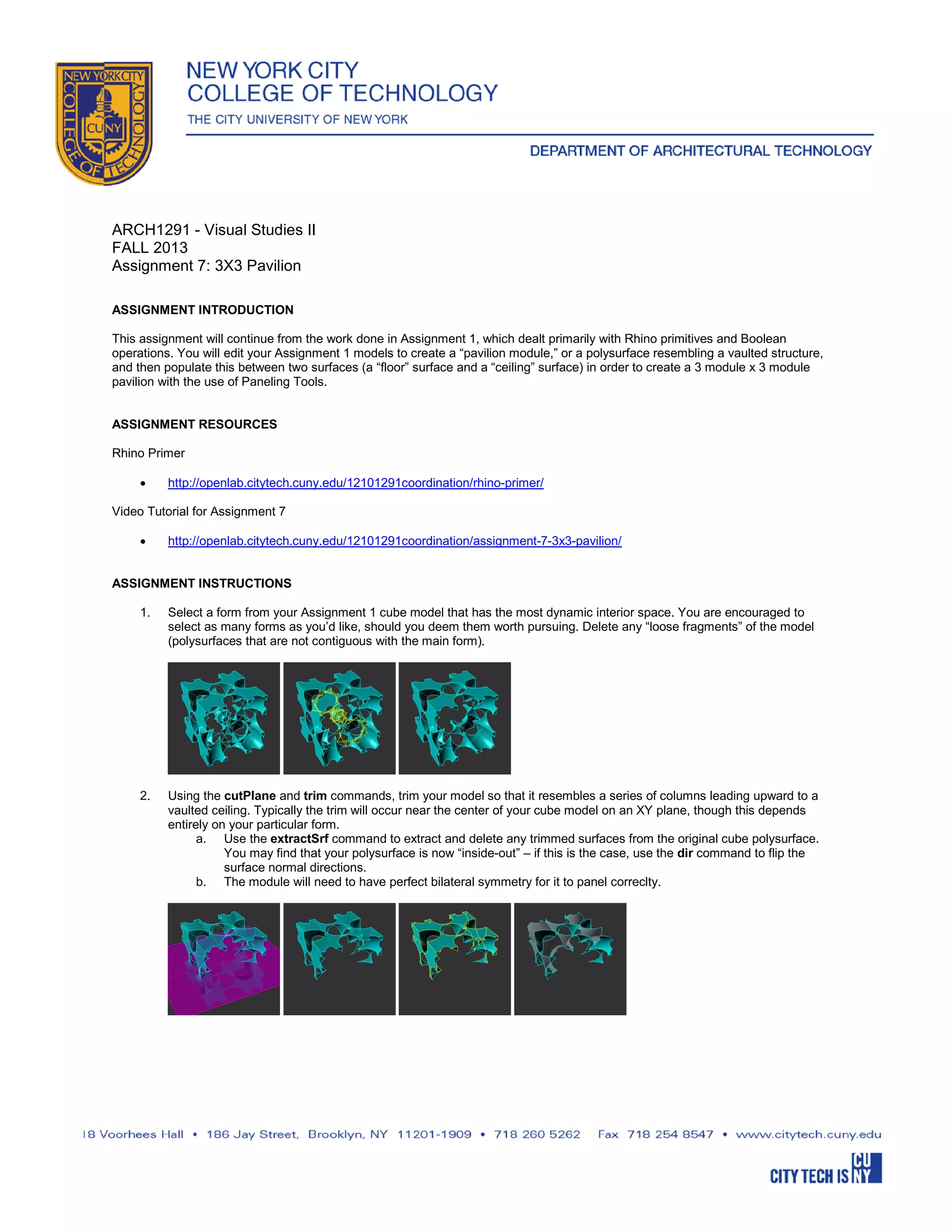
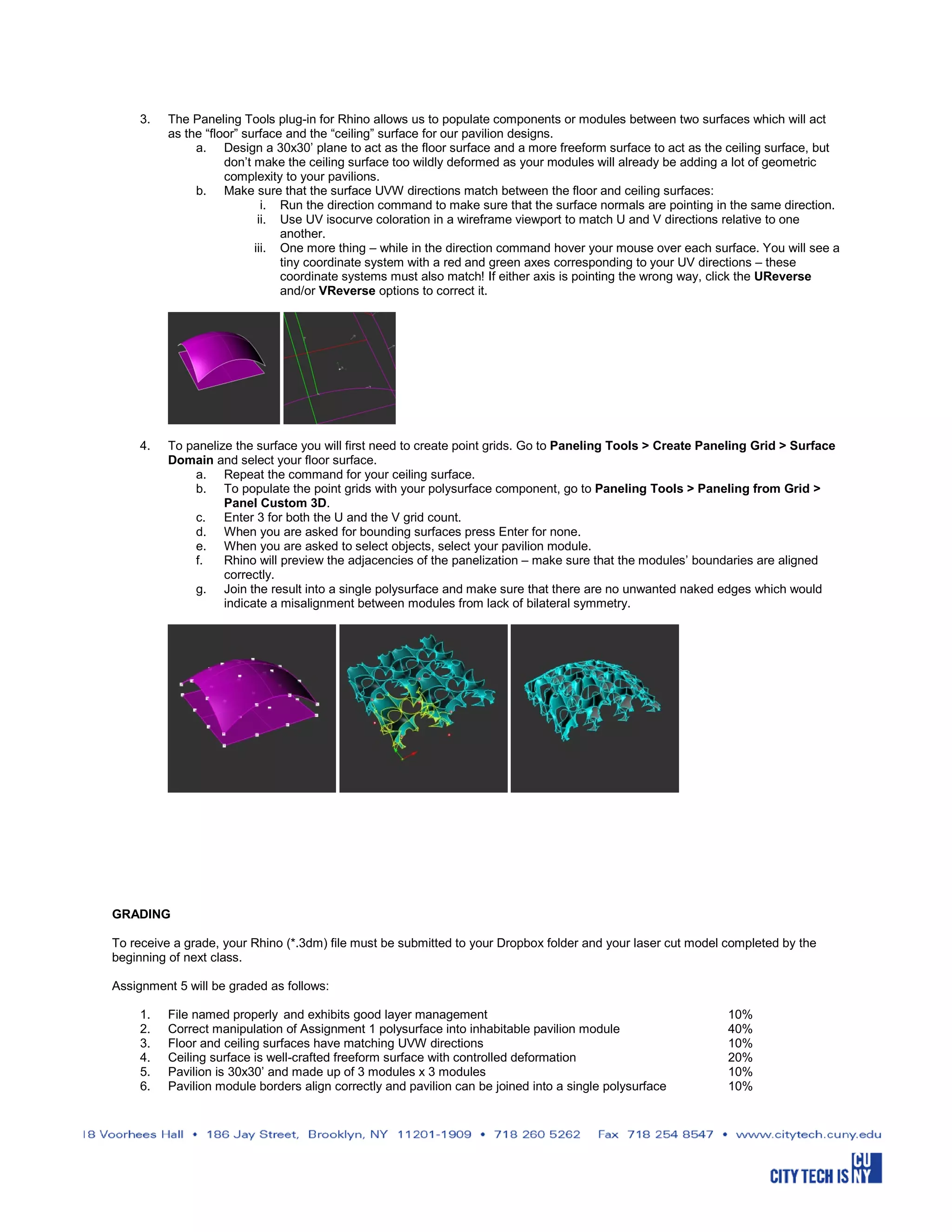
This assignment asks students to take the model they created in Assignment 1 and modify it to create a "pavilion module" or vaulted structure that can be replicated in a 3x3 grid to form a pavilion structure between a floor and ceiling surface using Rhino's Paneling Tools. Students are to trim their original model to create columns, extract surfaces, and ensure bilateral symmetry. They will then design floor and ceiling surfaces with matching UVW directions before using the Paneling Tools to populate their pavilion module in a 3x3 grid between the surfaces and joining it into a single polysurface. The assignment will be graded based on various criteria including file organization, module creation, surface matching, and correct panel population and alignment.
How to make pop-up design for novelty books, greeting cards and promotional media, from idea to production. See more paper ideas and designs at www.athiprem.strikingly.com
User guide of numerical simulation gridding v2.2.0Bo Sun
This is the user guide of DepthInsight™ numerical simulation gridding module. For corresponding video tutorials , please visit and subscribe our Youtube channel: https://www.youtube.com/channel/UCjHyG-mG7NQofUWTZgpBT2w
DepthInsight™ software products include modules as follows:
Structure Interpretation
Well and Data Management
Plan Module
Profile Module
Attribute Modeling
Velocity Modeling
Structural Modeling
Reservoir Geological Modeling
Numerical Simulation Gridding
Rock Modeling
Geo-mechanical Modeling
Paleo-Structural Modeling
Enormous Modeling Platform
For more information about our company, Beijing GridWorld Software Technology Co., Ltd., please visit our website: http://gridworld.com.cn/en/
1. ARCH1291 - Visual Studies II
FALL 2013
Assignment 7: 3X3 Pavilion
ASSIGNMENT INTRODUCTION
This assignment will continue from the work done in Assignment 1, which dealt primarily with Rhino primitives and Boolean
operations. You will edit your Assignment 1 models to create a “pavilion module,” or a polysurface resembling a vaulted structure,
and then populate this between two surfaces (a “floor” surface and a “ceiling” surface) in order to create a 3 module x 3 module
pavilion with the use of Paneling Tools.
ASSIGNMENT RESOURCES
Rhino Primer
•
http://openlab.citytech.cuny.edu/12101291coordination/rhino-primer/
Video Tutorial for Assignment 7
•
http://openlab.citytech.cuny.edu/12101291coordination/assignment-7-3x3-pavilion/
ASSIGNMENT INSTRUCTIONS
1.
Select a form from your Assignment 1 cube model that has the most dynamic interior space. You are encouraged to
select as many forms as you’d like, should you deem them worth pursuing. Delete any “loose fragments” of the model
(polysurfaces that are not contiguous with the main form).
2.
Using the cutPlane and trim commands, trim your model so that it resembles a series of columns leading upward to a
vaulted ceiling. Typically the trim will occur near the center of your cube model on an XY plane, though this depends
entirely on your particular form.
a. Use the extractSrf command to extract and delete any trimmed surfaces from the original cube polysurface.
You may find that your polysurface is now “inside-out” – if this is the case, use the dir command to flip the
surface normal directions.
b. The module will need to have perfect bilateral symmetry for it to panel correclty.
2. 3.
The Paneling Tools plug-in for Rhino allows us to populate components or modules between two surfaces which will act
as the “floor” surface and the “ceiling” surface for our pavilion designs.
a. Design a 30x30’ plane to act as the floor surface and a more freeform surface to act as the ceiling surface, but
don’t make the ceiling surface too wildly deformed as your modules will already be adding a lot of geometric
complexity to your pavilions.
b. Make sure that the surface UVW directions match between the floor and ceiling surfaces:
i. Run the direction command to make sure that the surface normals are pointing in the same direction.
ii. Use UV isocurve coloration in a wireframe viewport to match U and V directions relative to one
another.
iii. One more thing – while in the direction command hover your mouse over each surface. You will see a
tiny coordinate system with a red and green axes corresponding to your UV directions – these
coordinate systems must also match! If either axis is pointing the wrong way, click the UReverse
and/or VReverse options to correct it.
4.
To panelize the surface you will first need to create point grids. Go to Paneling Tools > Create Paneling Grid > Surface
Domain and select your floor surface.
a. Repeat the command for your ceiling surface.
b. To populate the point grids with your polysurface component, go to Paneling Tools > Paneling from Grid >
Panel Custom 3D.
c. Enter 3 for both the U and the V grid count.
d. When you are asked for bounding surfaces press Enter for none.
e. When you are asked to select objects, select your pavilion module.
f.
Rhino will preview the adjacencies of the panelization – make sure that the modules’ boundaries are aligned
correctly.
g. Join the result into a single polysurface and make sure that there are no unwanted naked edges which would
indicate a misalignment between modules from lack of bilateral symmetry.
GRADING
To receive a grade, your Rhino (*.3dm) file must be submitted to your Dropbox folder and your laser cut model completed by the
beginning of next class.
Assignment 5 will be graded as follows:
1.
2.
3.
4.
5.
6.
File named properly and exhibits good layer management
Correct manipulation of Assignment 1 polysurface into inhabitable pavilion module
Floor and ceiling surfaces have matching UVW directions
Ceiling surface is well-crafted freeform surface with controlled deformation
Pavilion is 30x30’ and made up of 3 modules x 3 modules
Pavilion module borders align correctly and pavilion can be joined into a single polysurface
10%
40%
10%
20%
10%
10%