Download to read offline


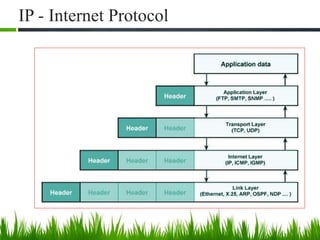
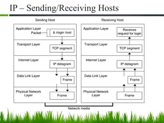
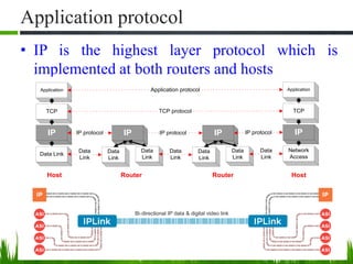
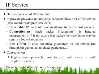
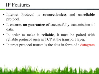

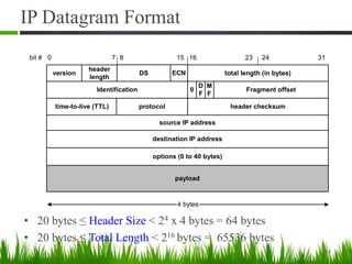
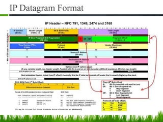


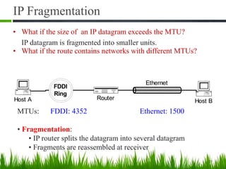
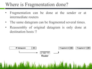
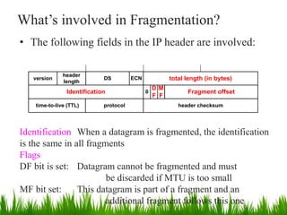
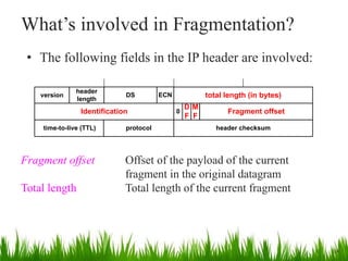
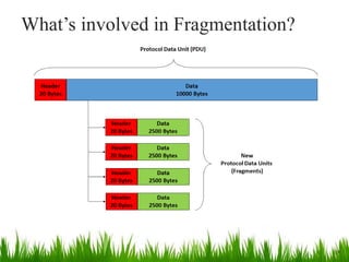
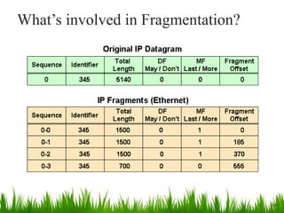
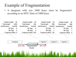


IP is the principal communications protocol in the Internet protocol suite for relaying datagrams across network boundaries. It is a connectionless, best-effort protocol that does not guarantee delivery. IP packets can be fragmented into smaller units if their size exceeds the maximum transmission unit of the network. Fragmentation involves splitting the packet into multiple fragments that contain the same identification field but varying fragment offset and total length fields. The fragments are reassembled into the original packet at the destination.


![07 coms 525 tcpip - udp [autosaved]](https://cdn.slidesharecdn.com/ss_thumbnails/07-coms525tcpip-udpautosaved-200102103428-thumbnail.jpg?width=640&height=640&fit=bounds)


