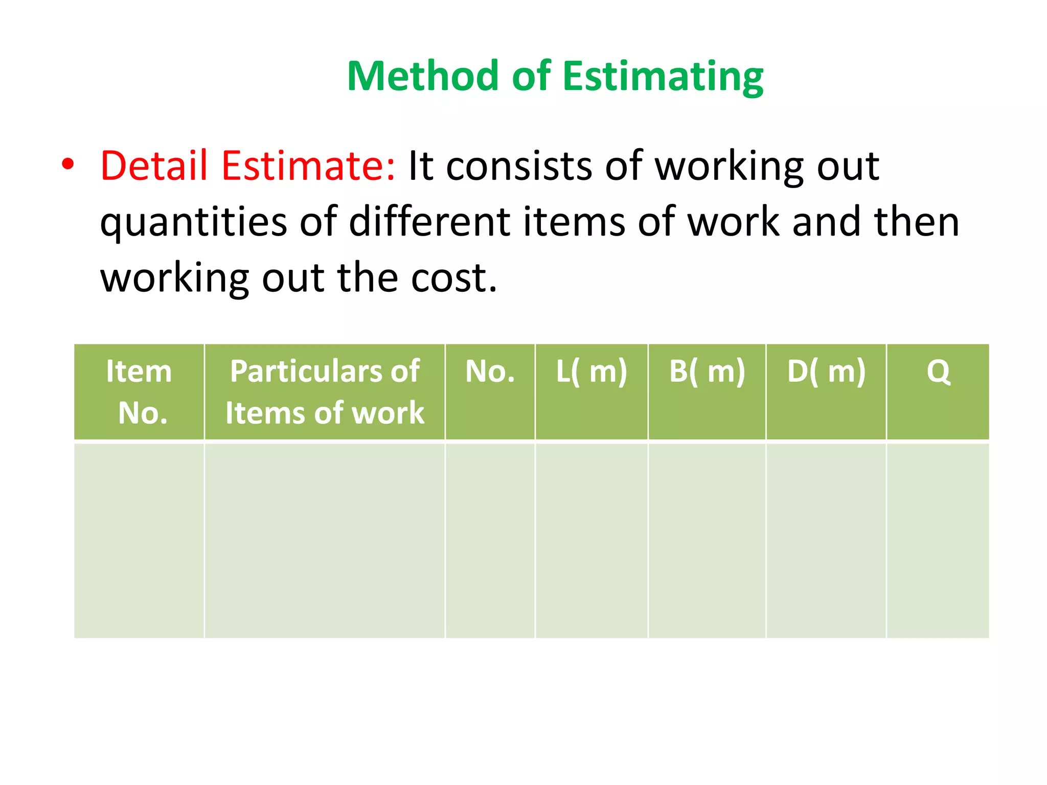
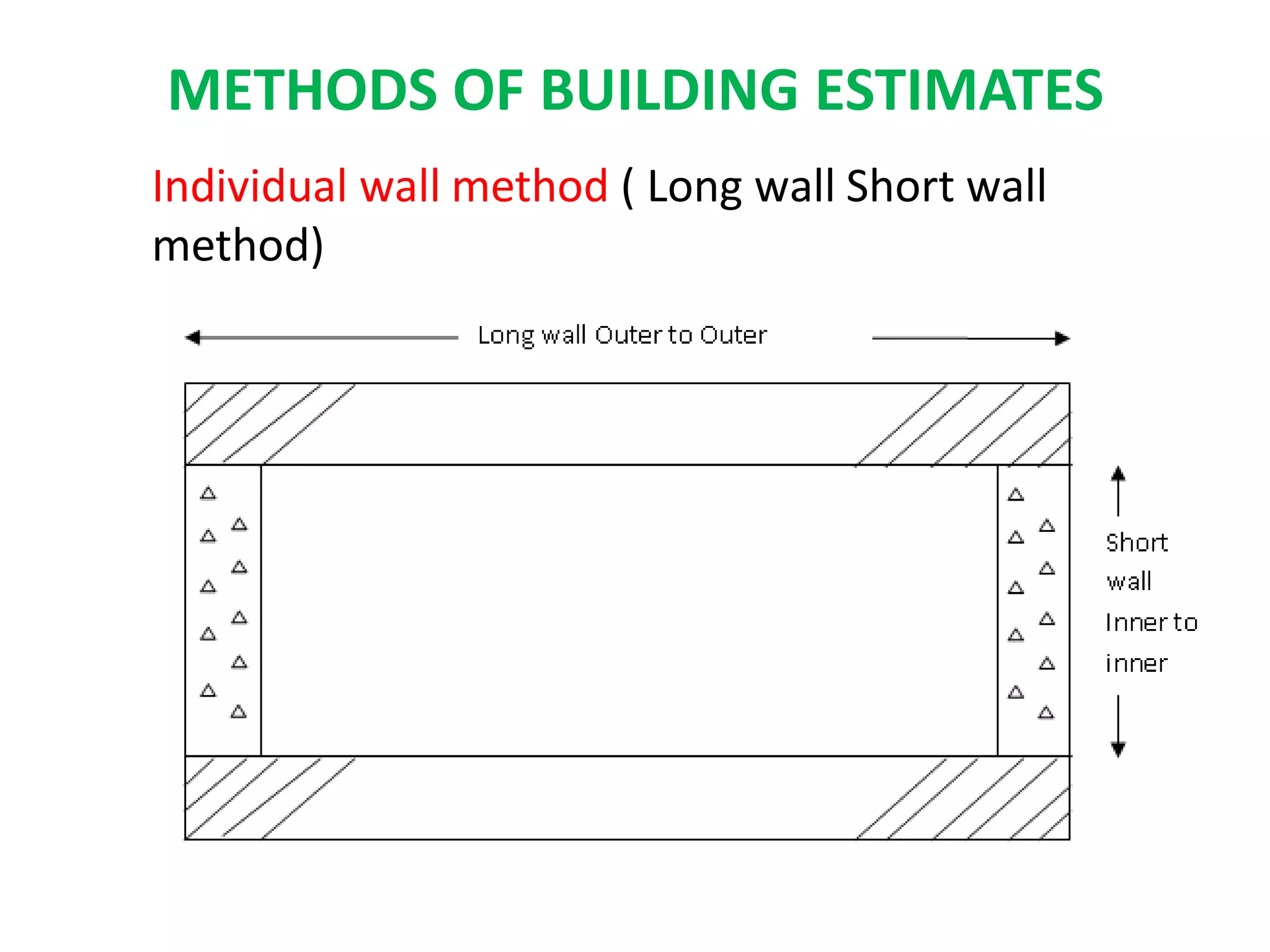
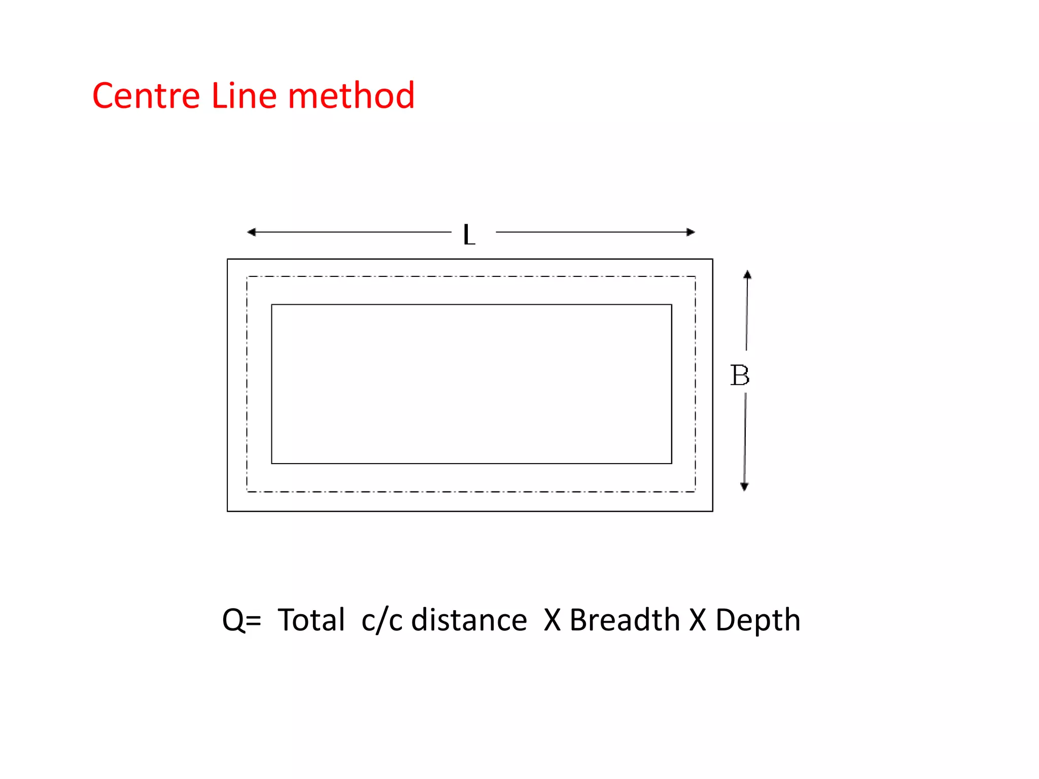
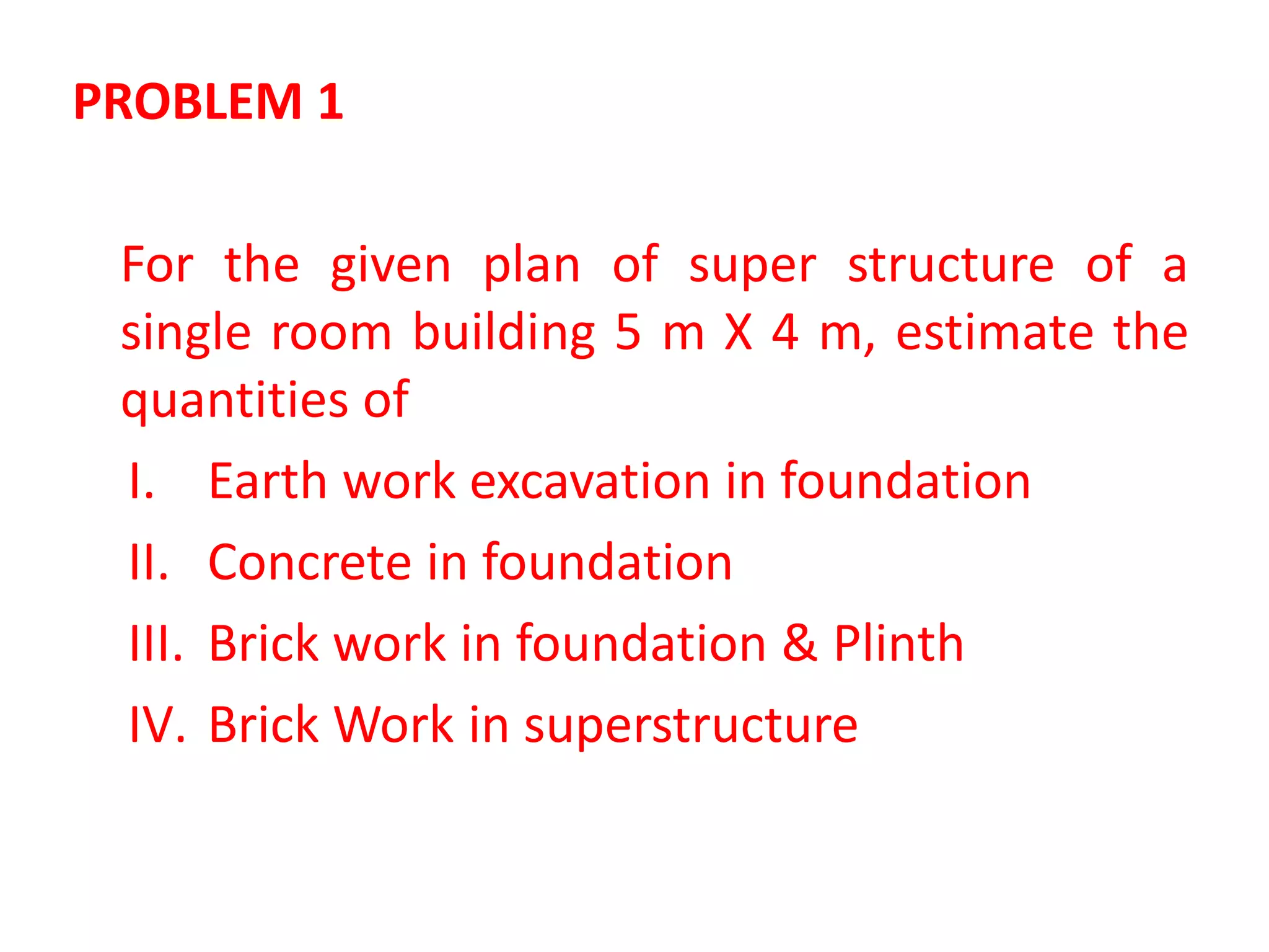
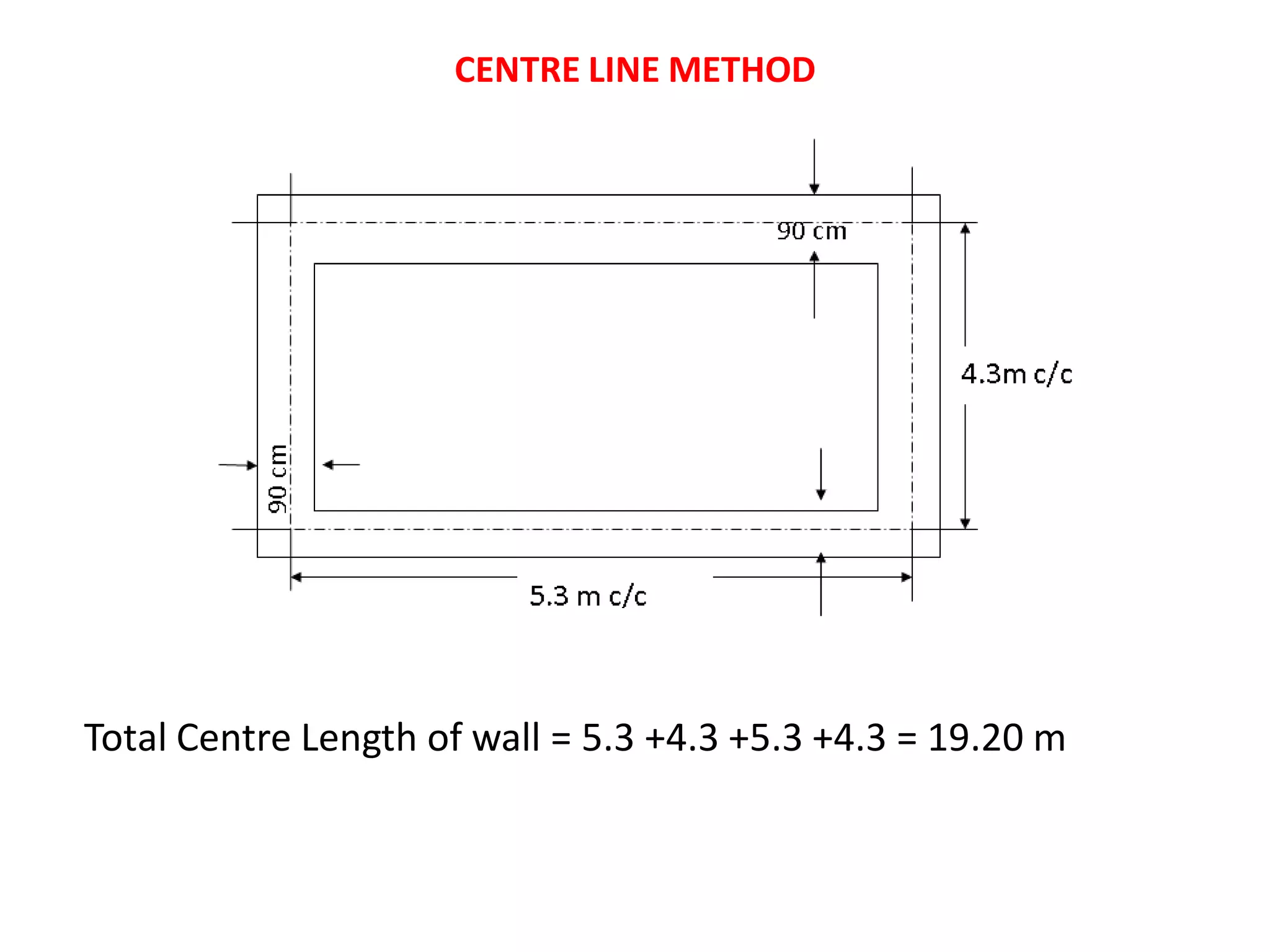
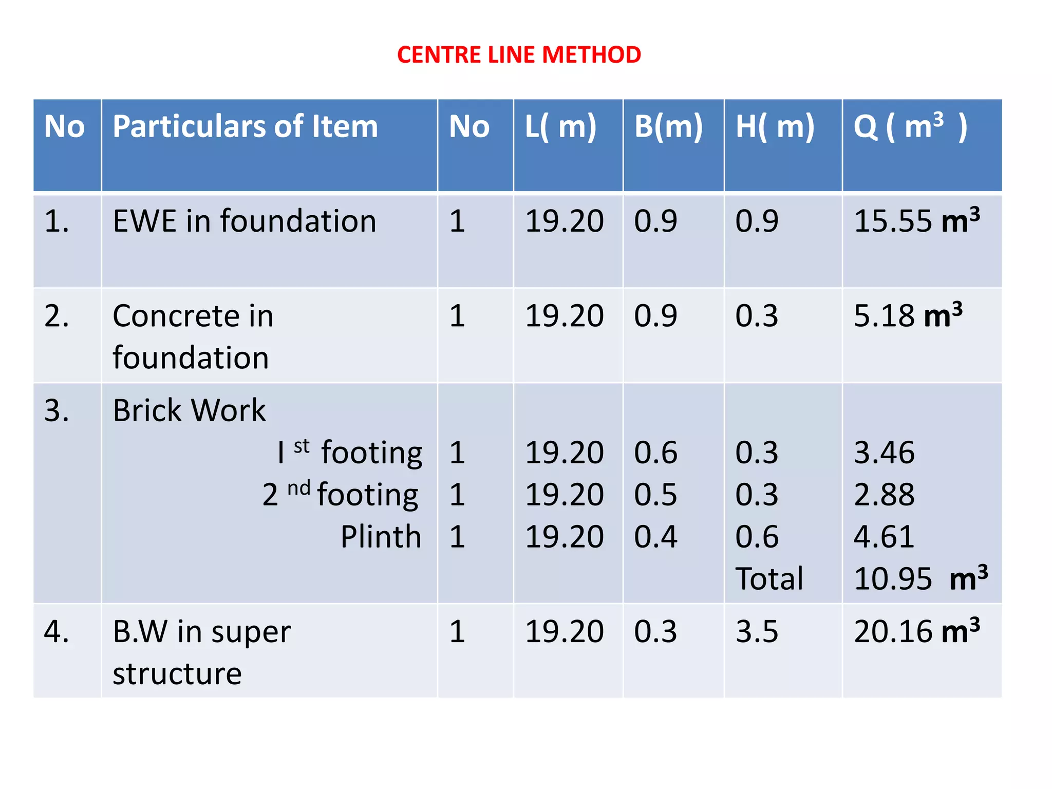
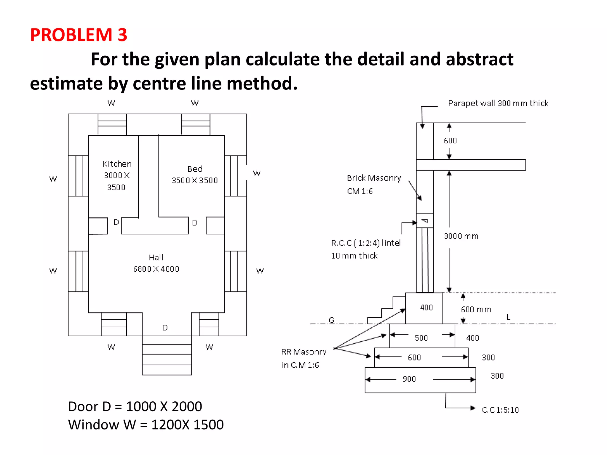
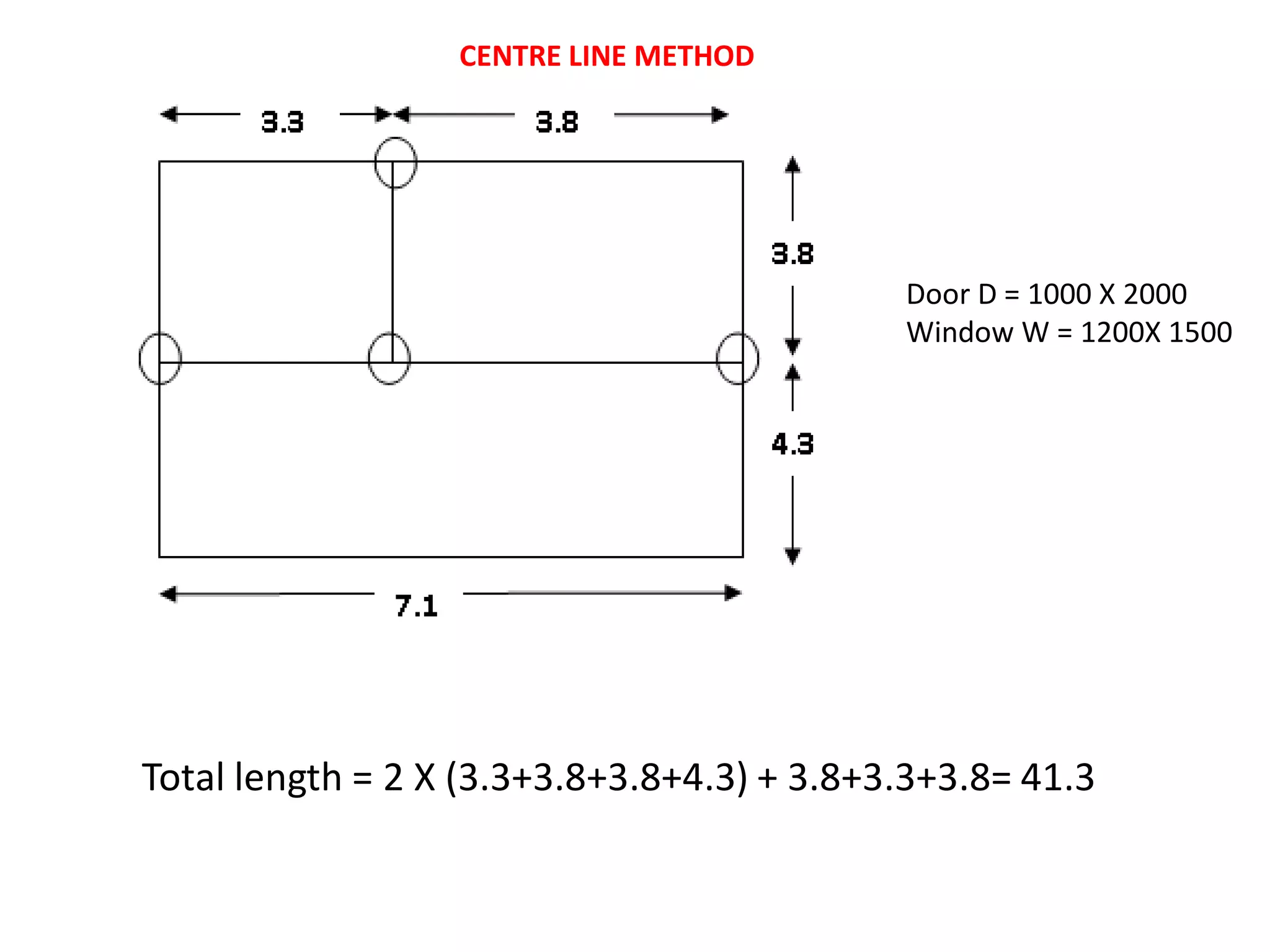
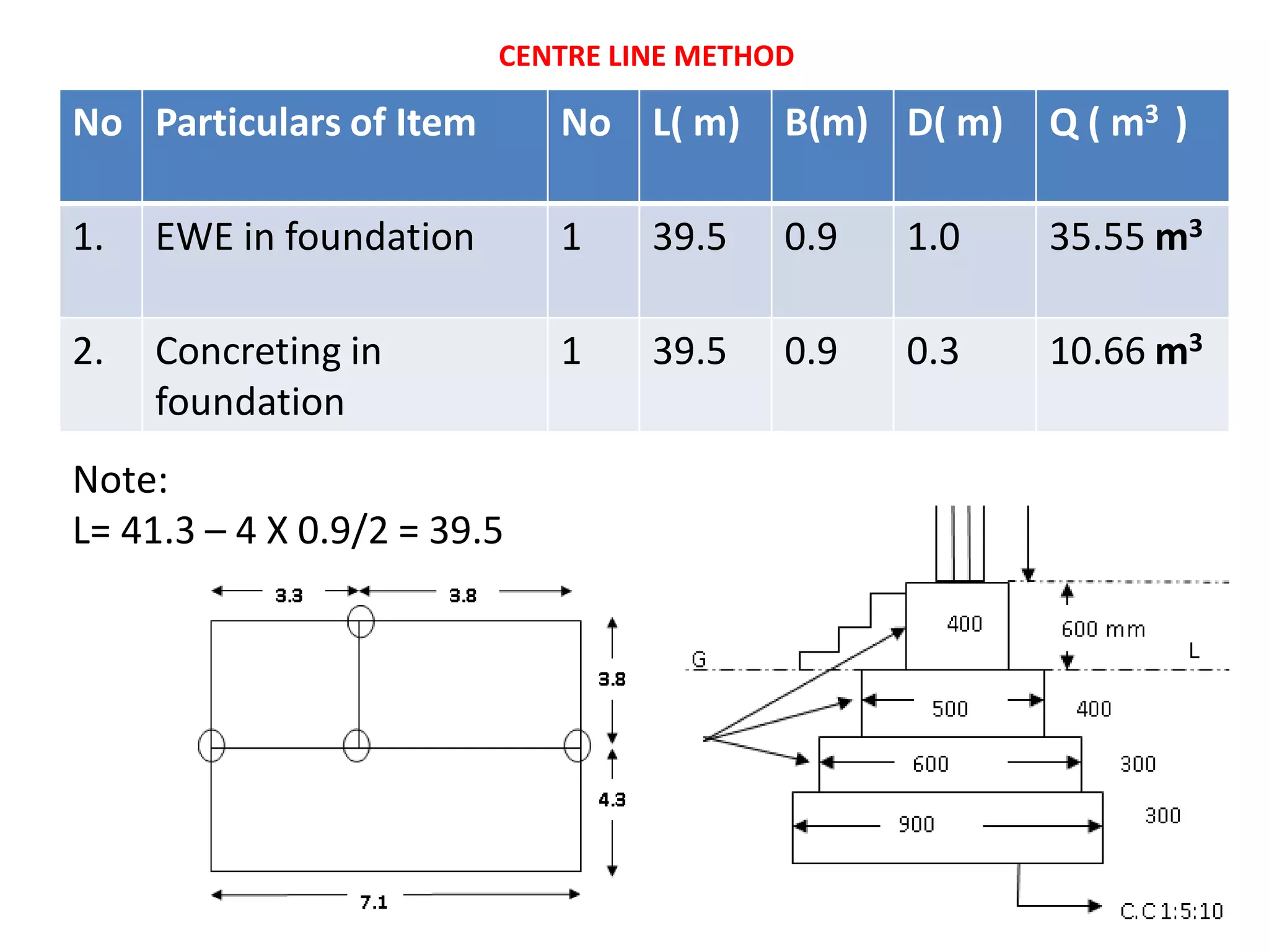
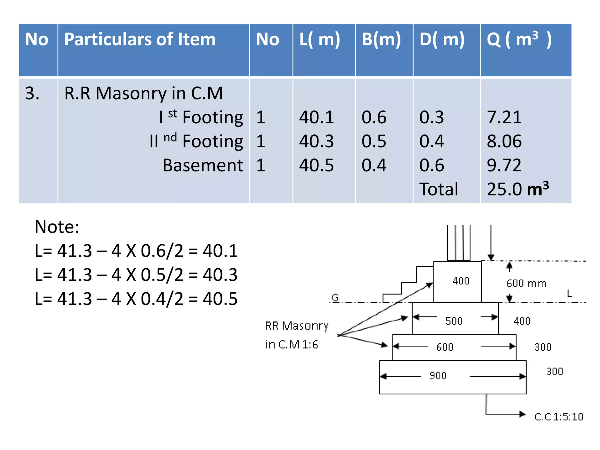
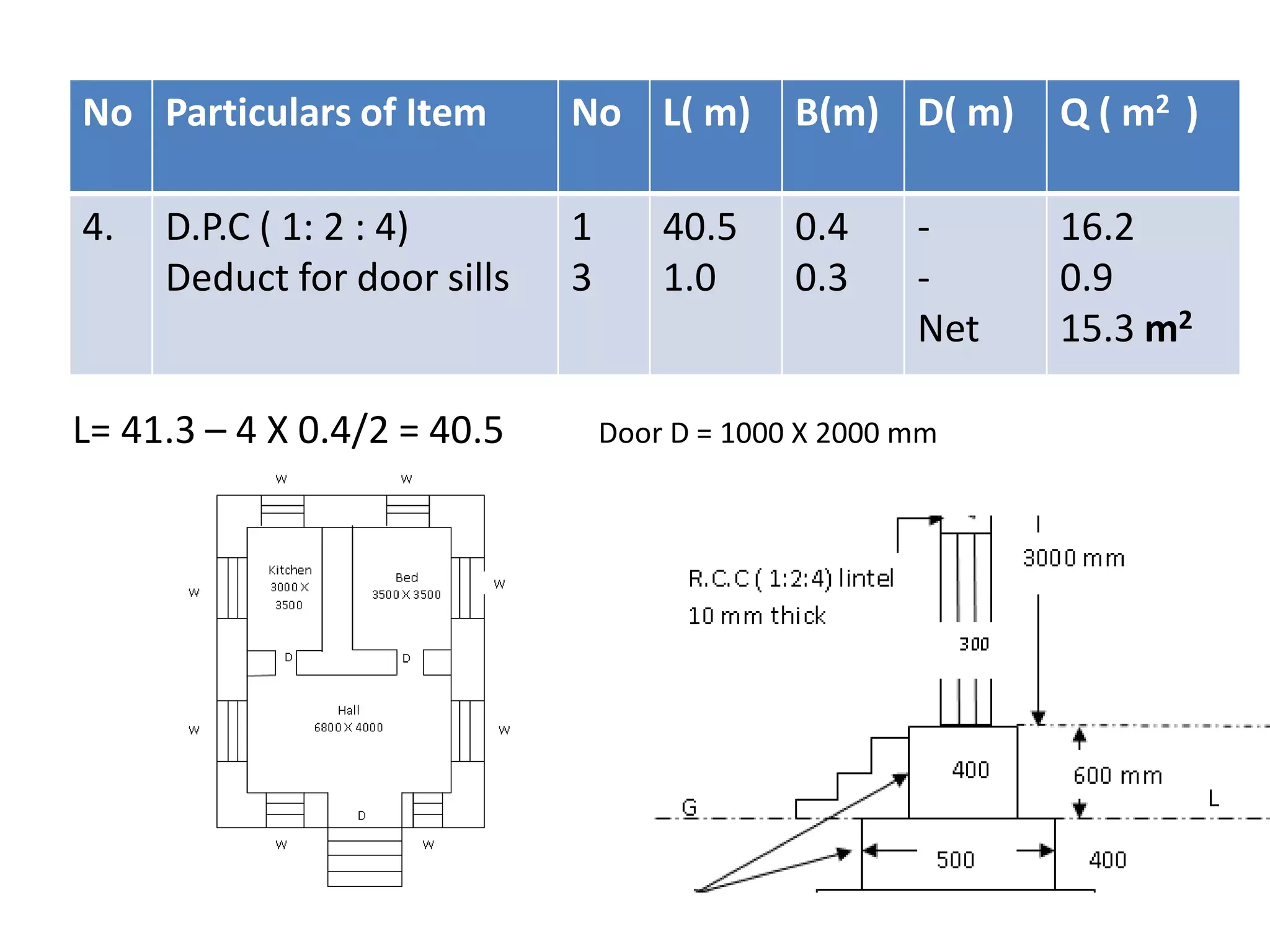
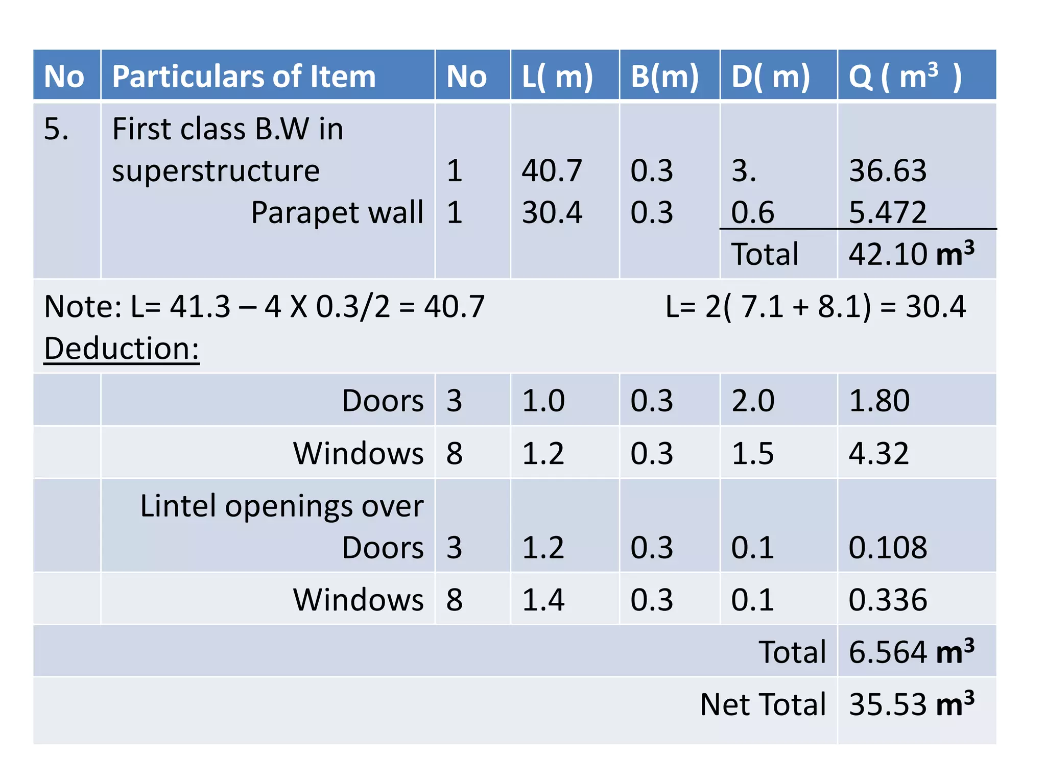
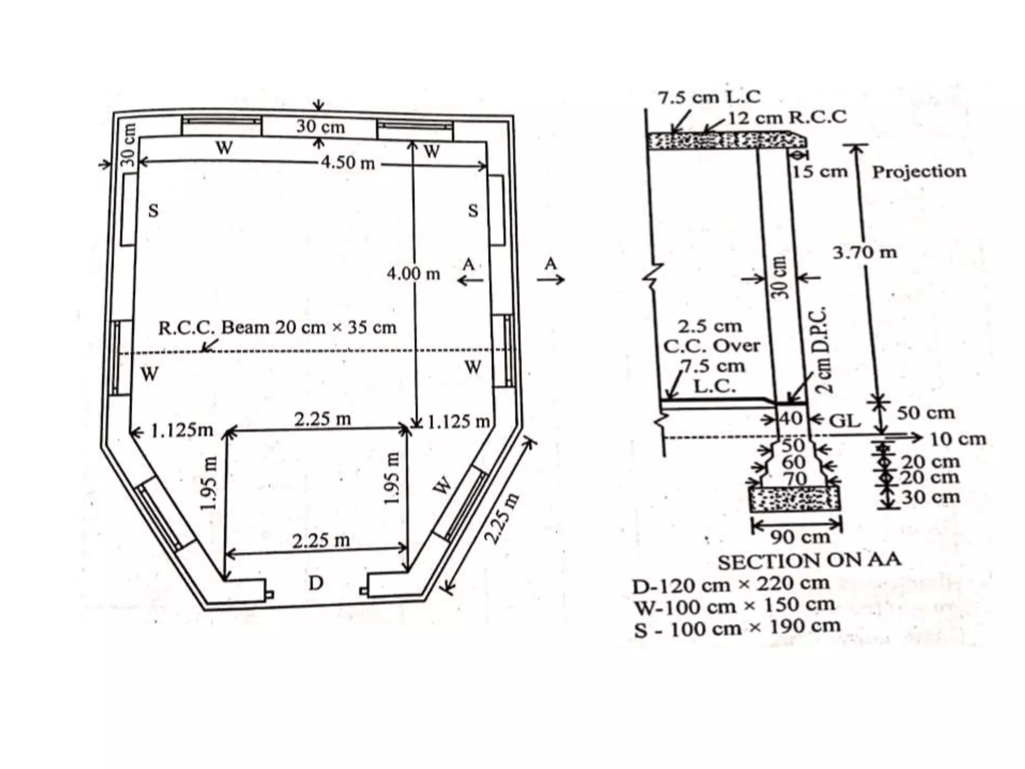
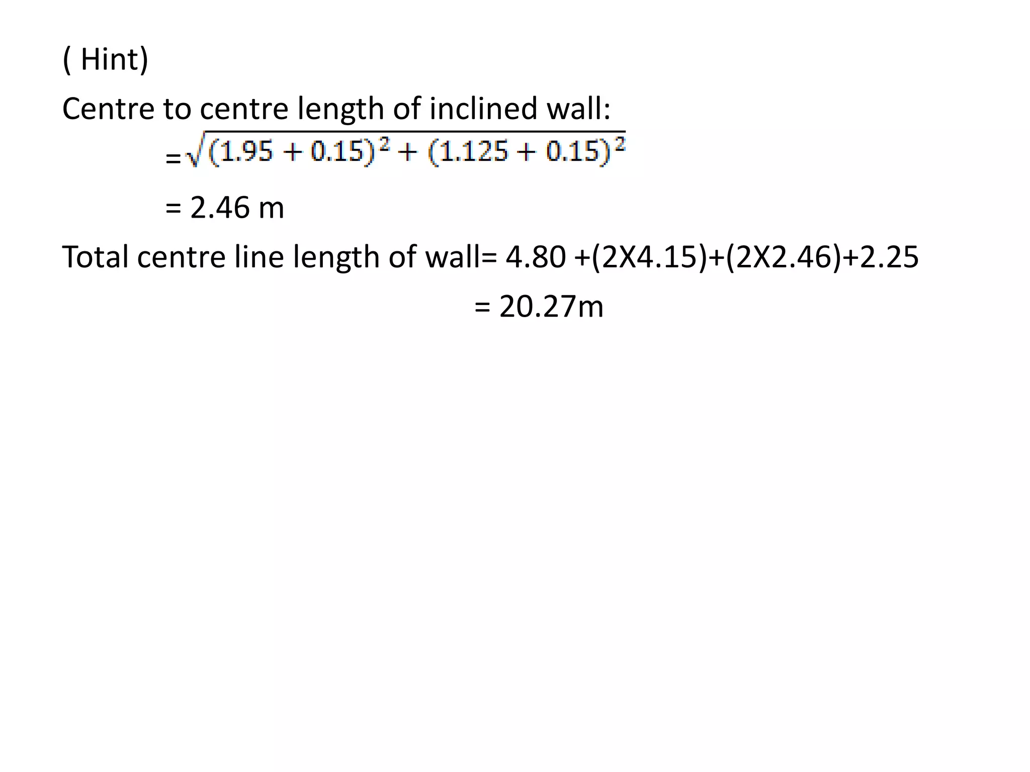
1. The document provides details on estimating quantities for various items of work for building construction projects using different methods like long wall short wall method, center line method, etc.
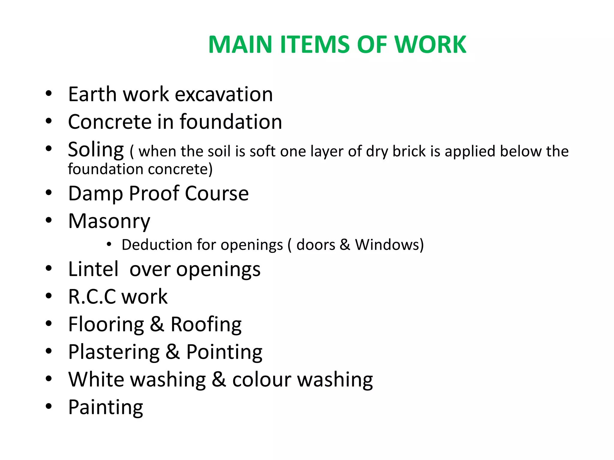
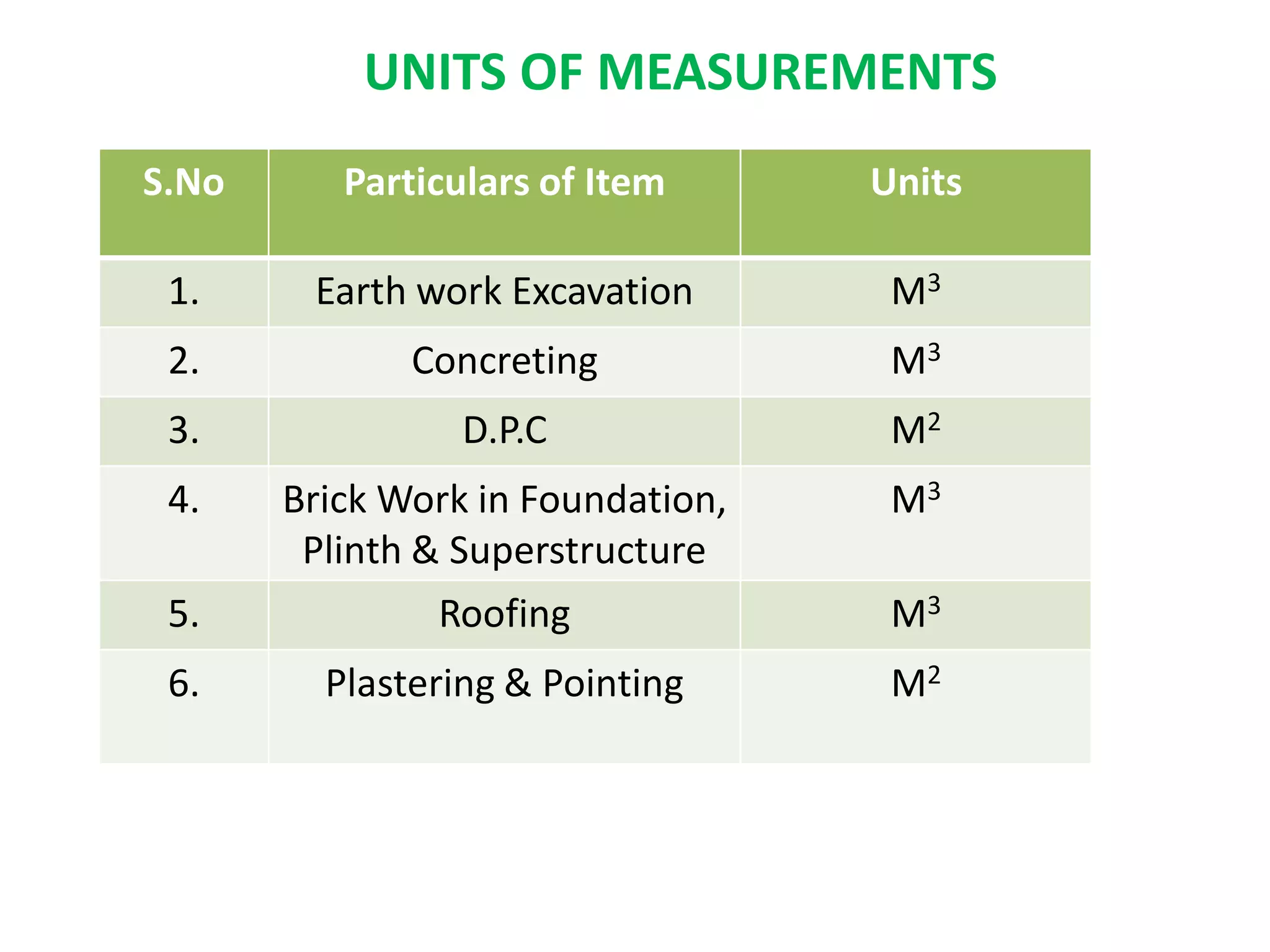
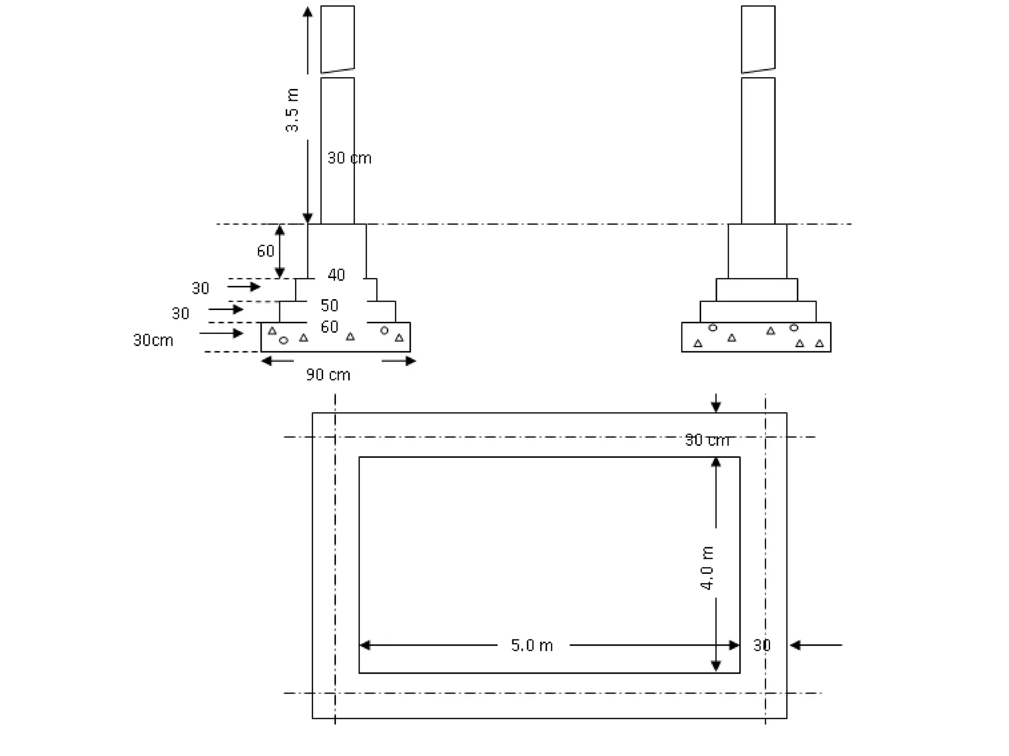
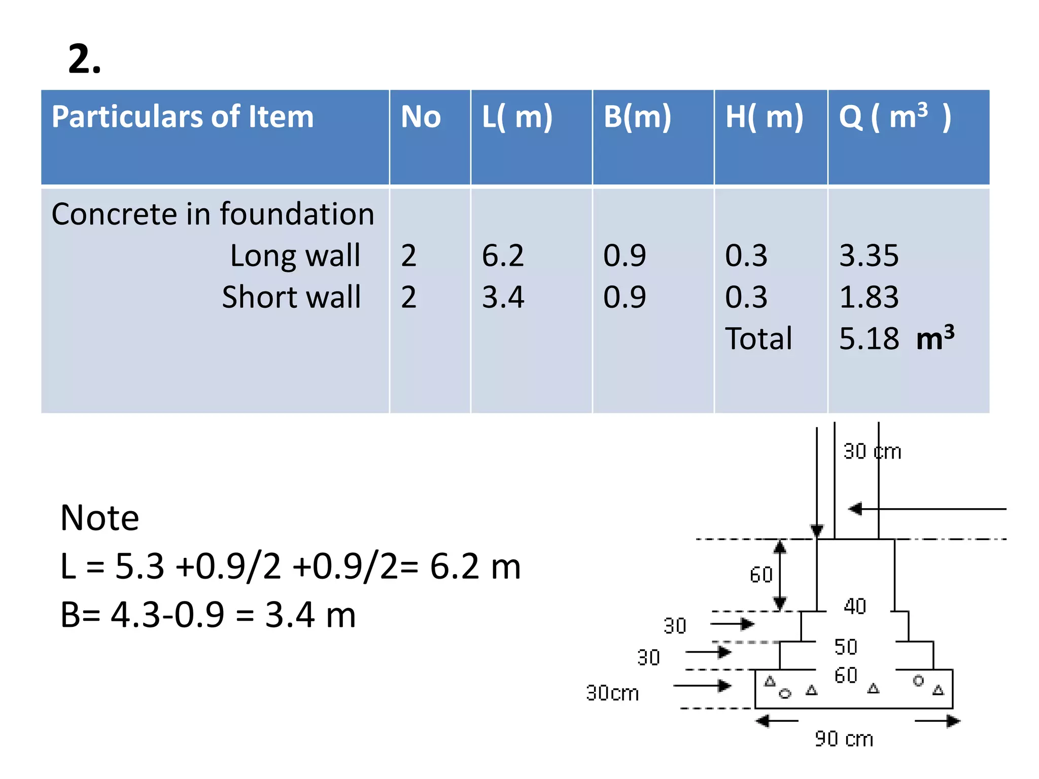
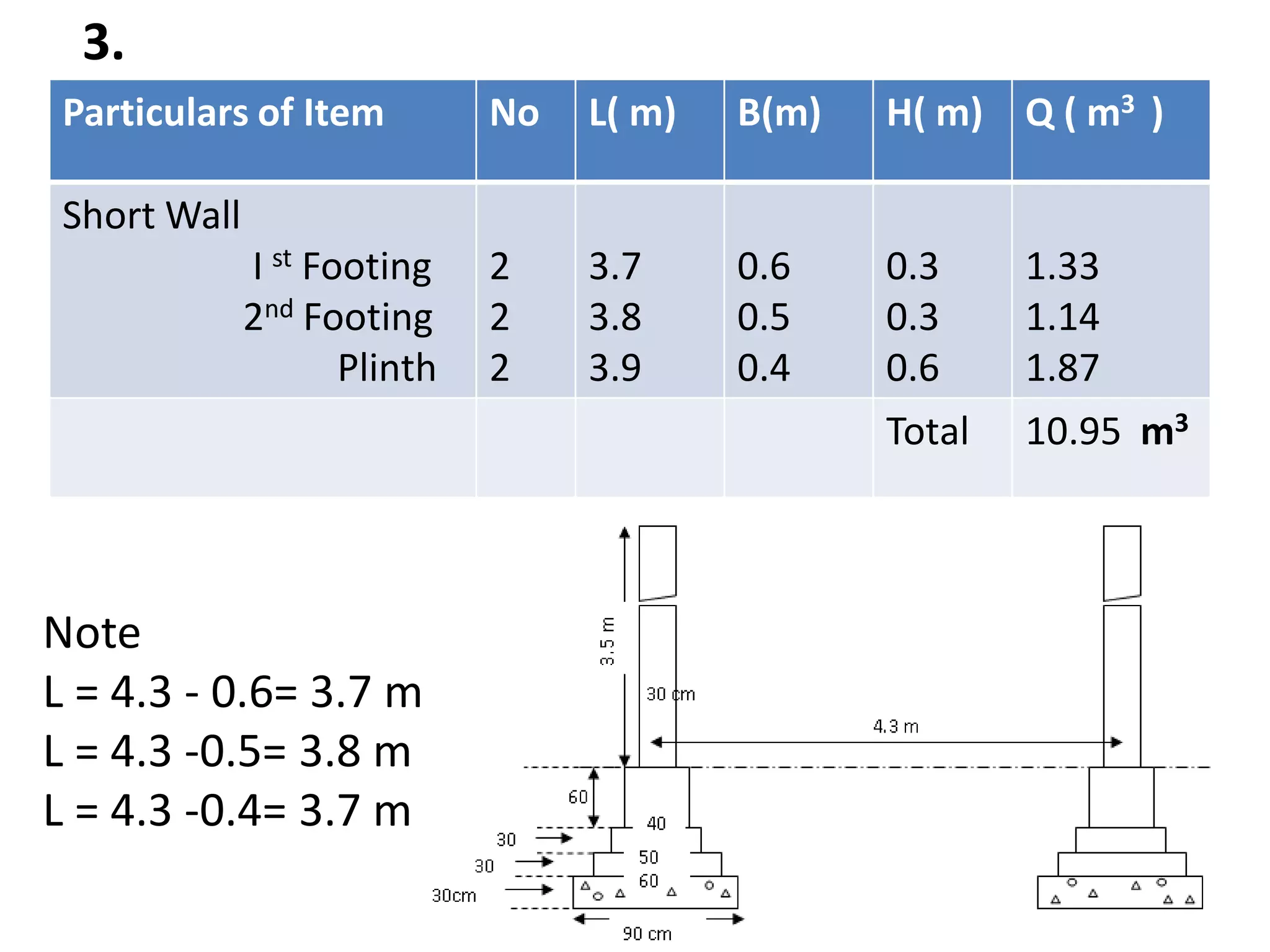
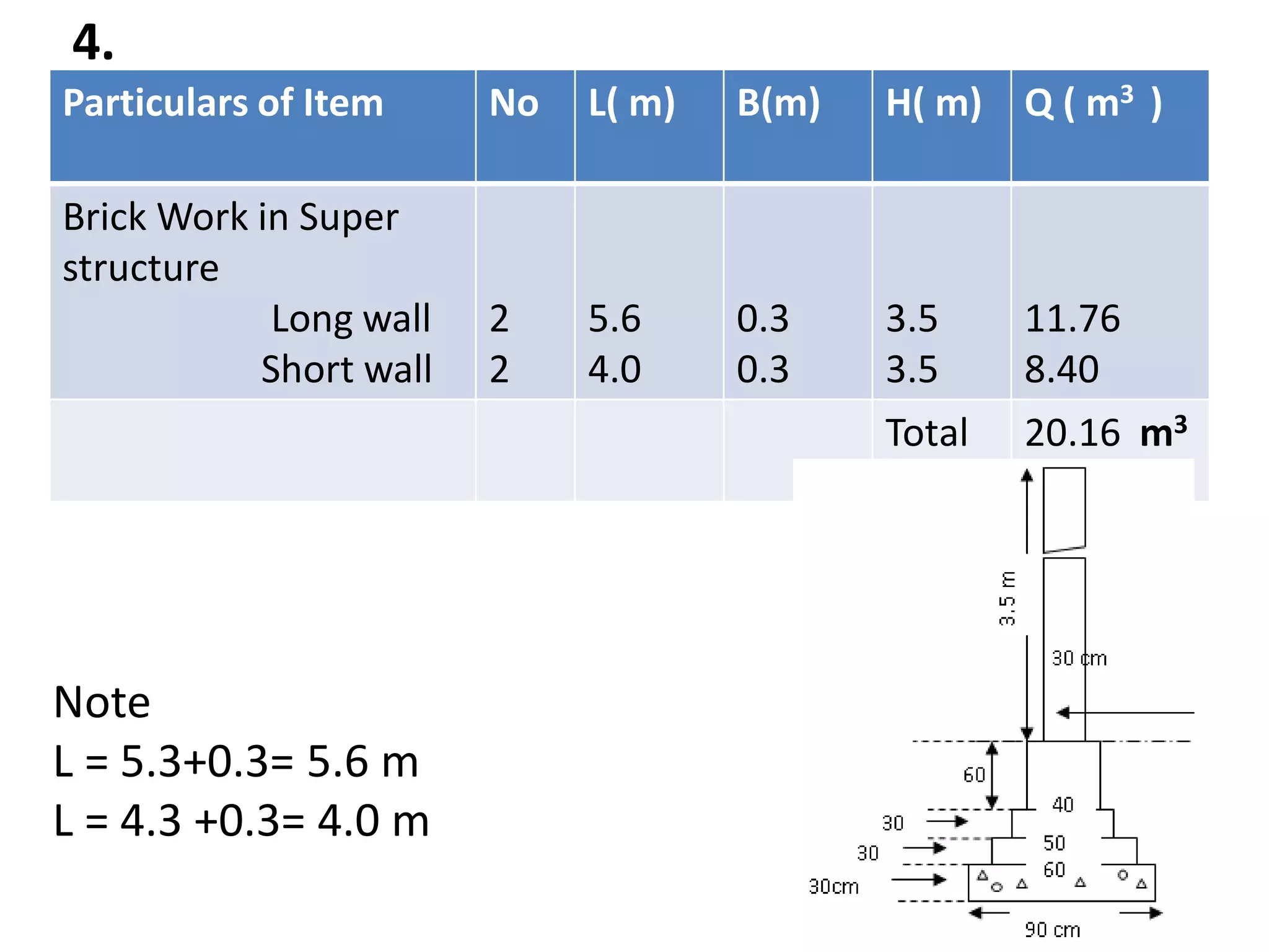
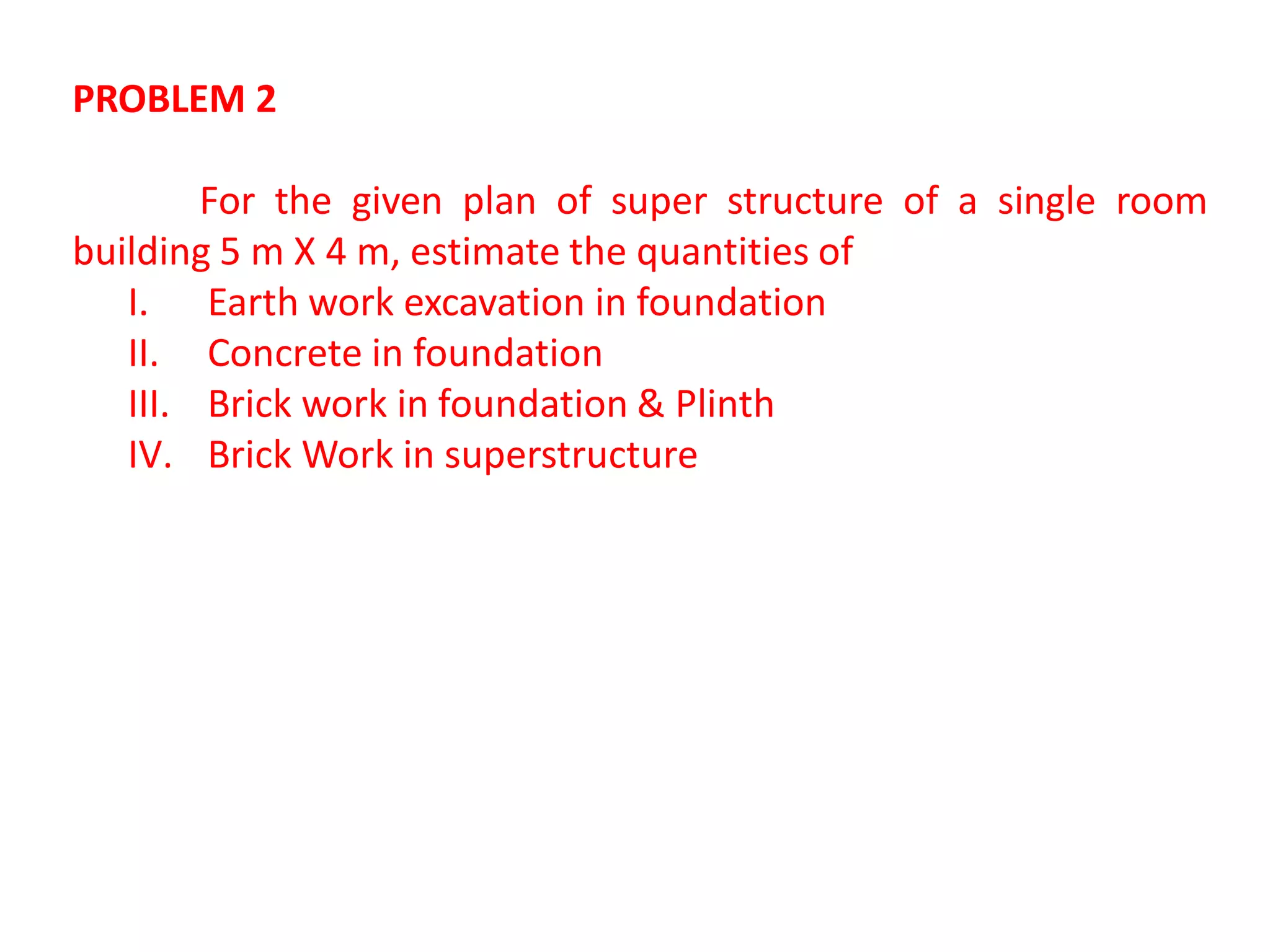
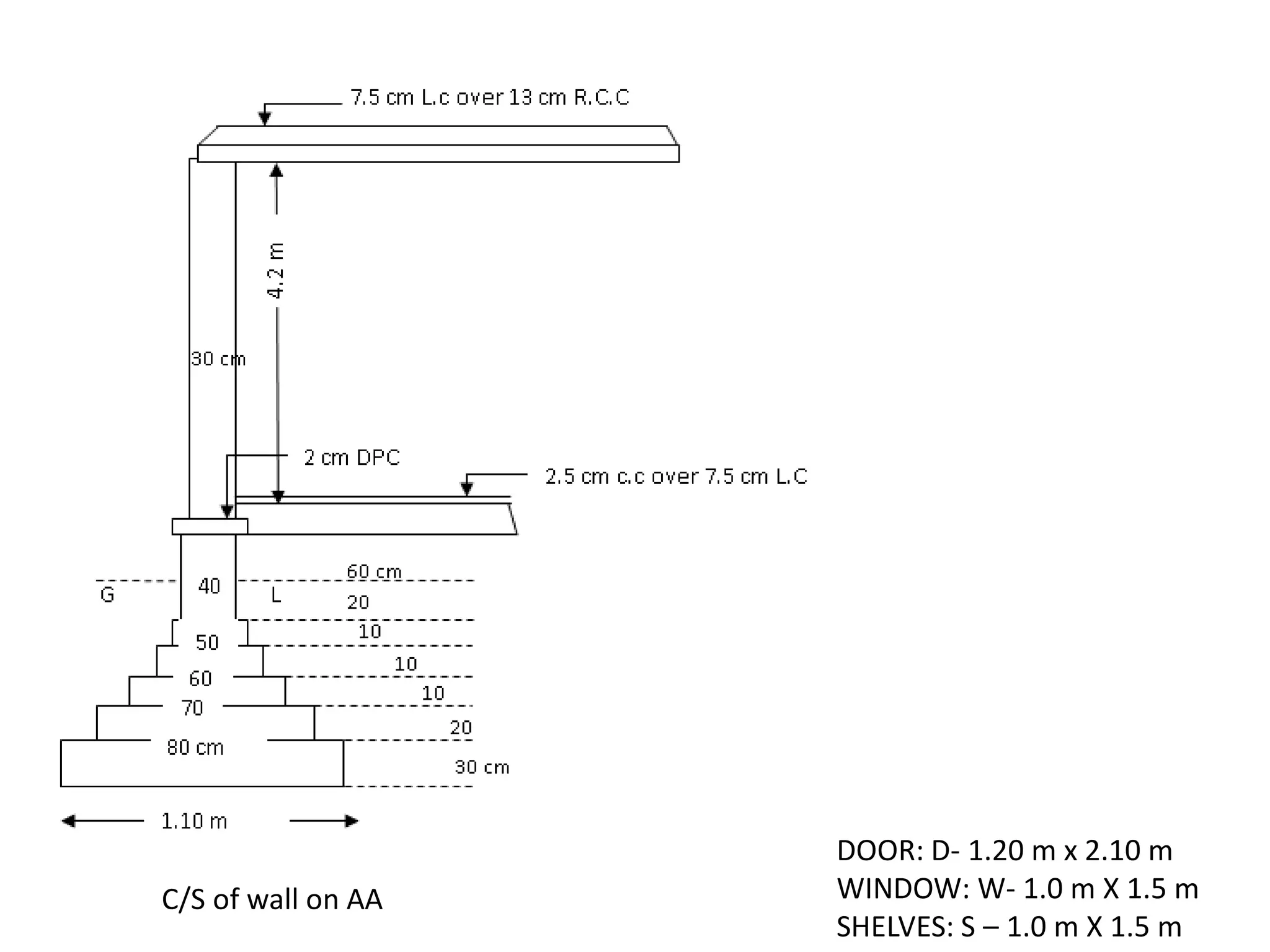
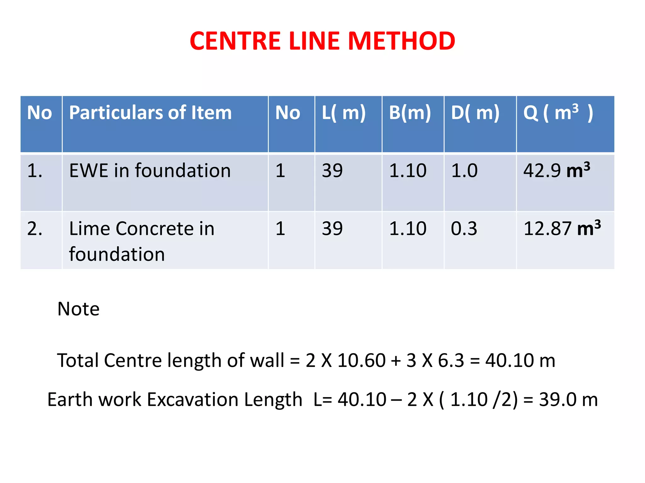
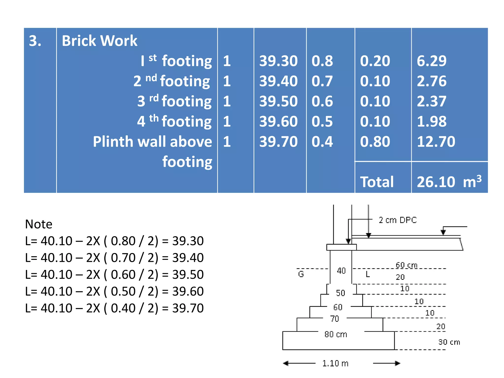
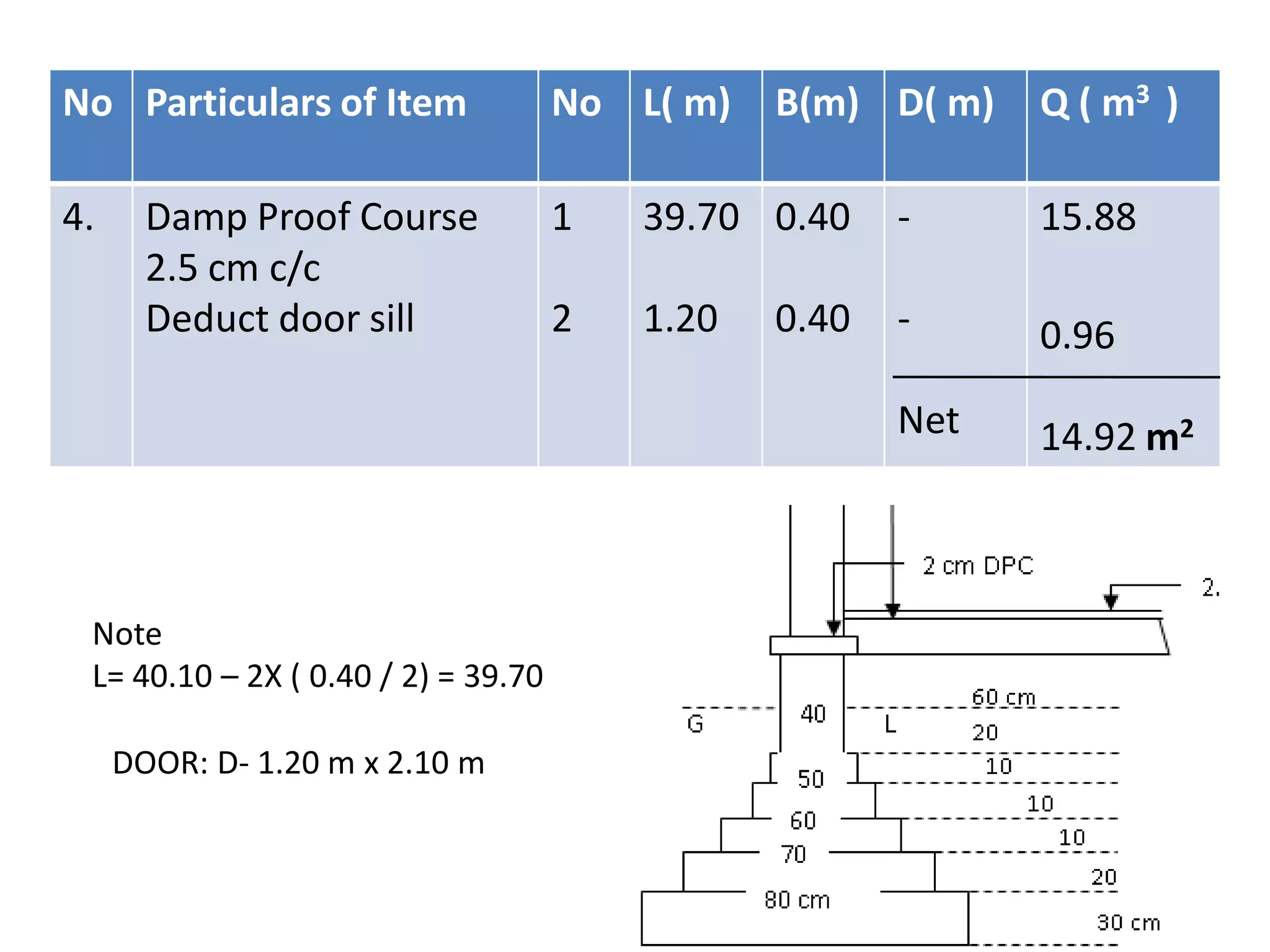
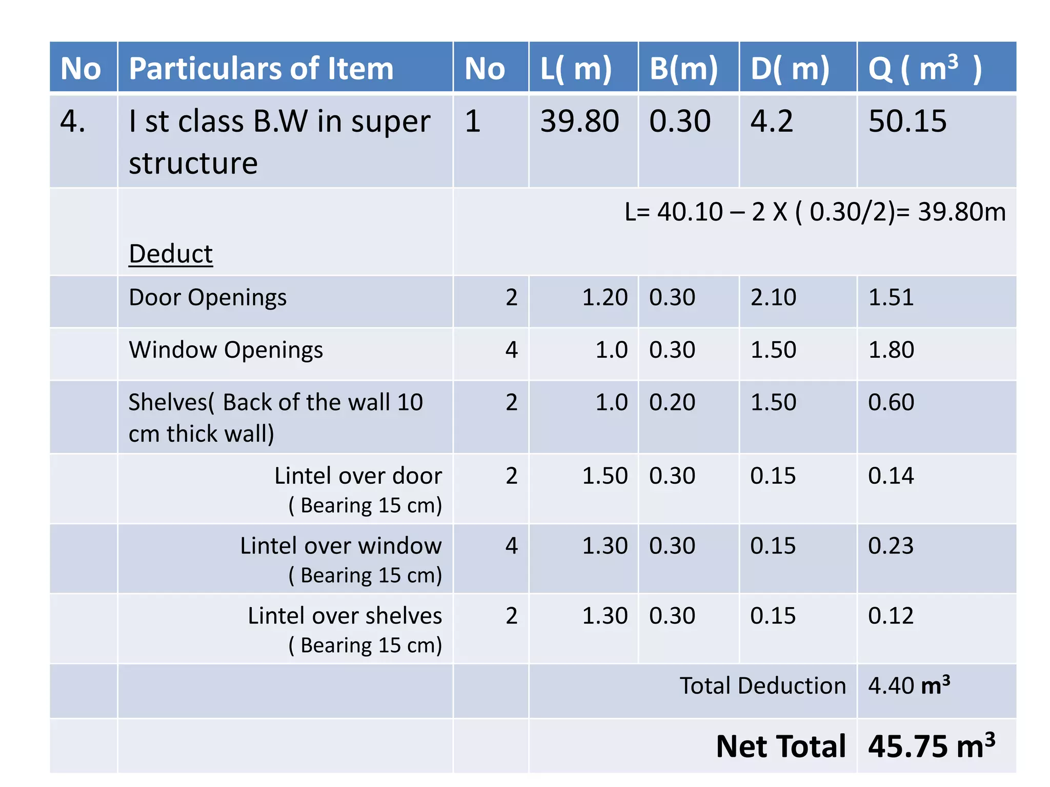
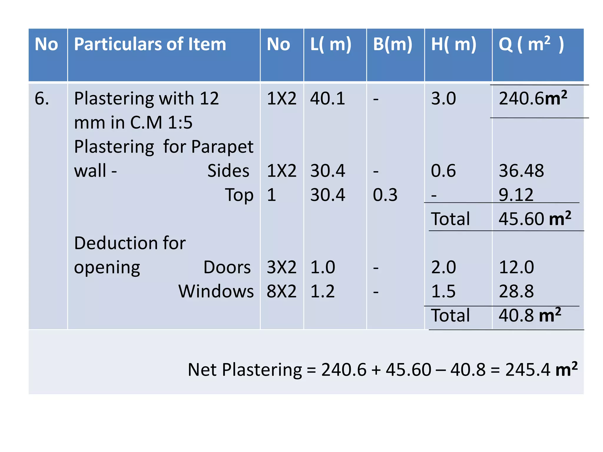
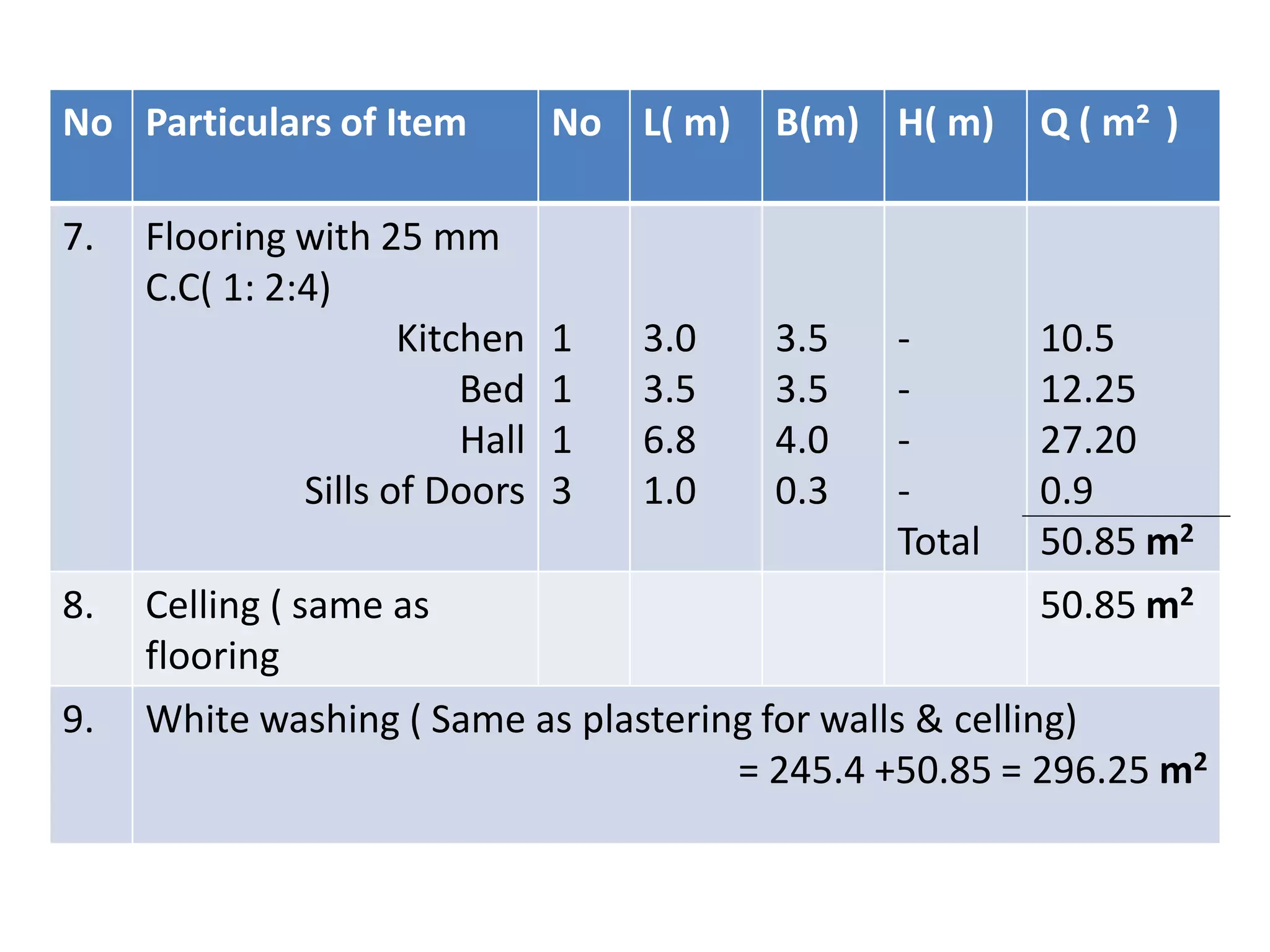
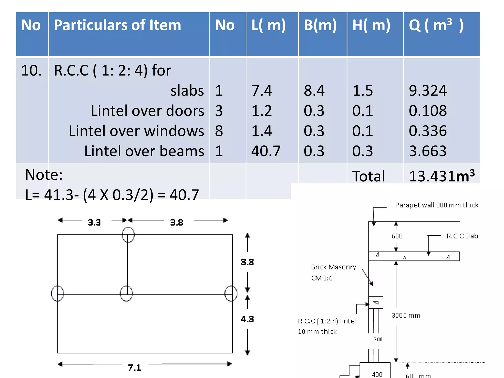
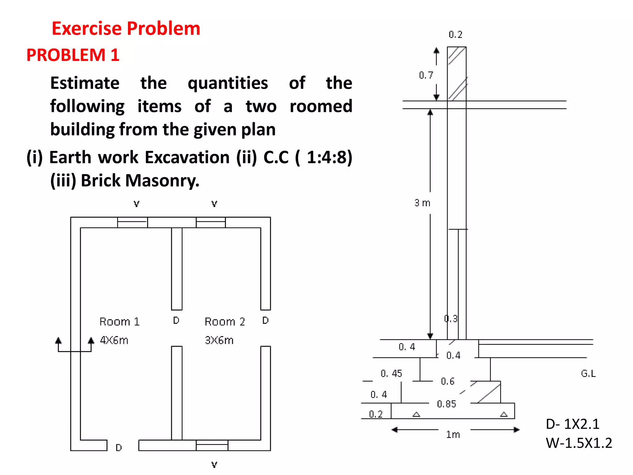
2. It includes examples calculating quantities of items like earthwork excavation, concrete, brickwork, plastering, etc. for single room and two room buildings.
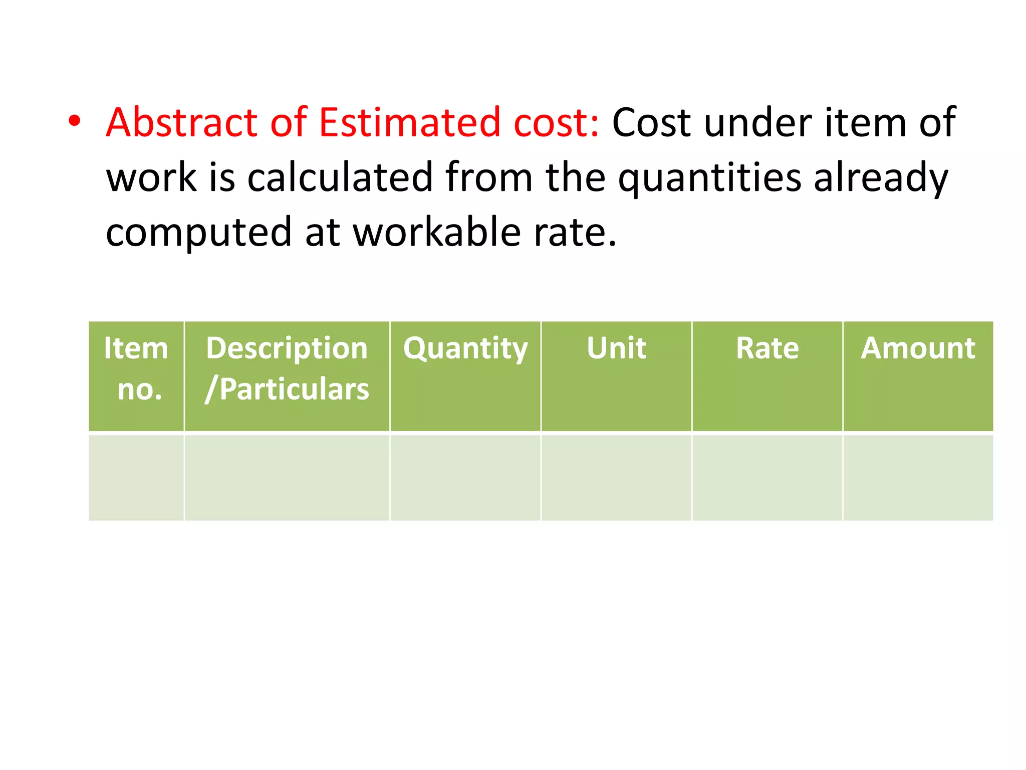
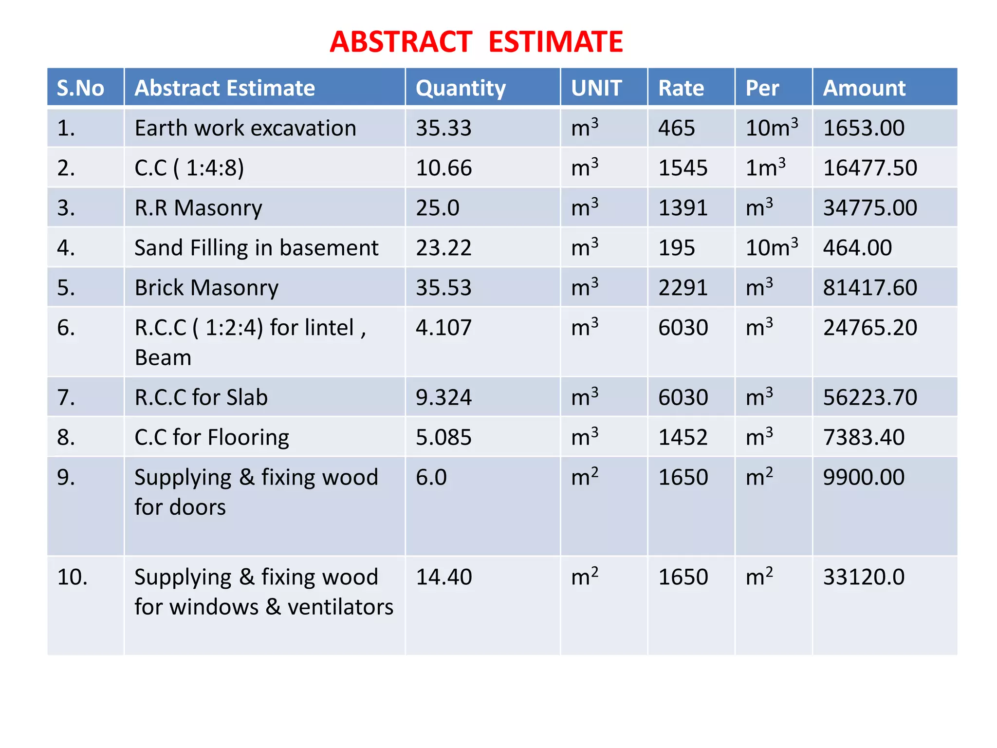
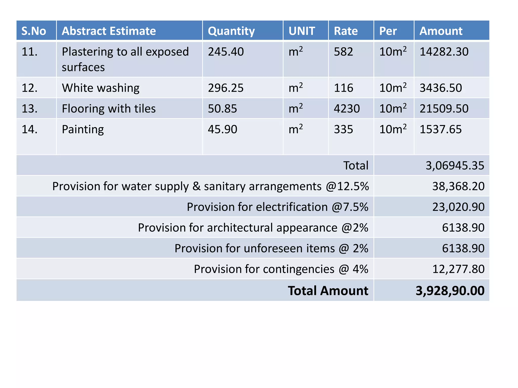
3. The document also shows an abstract estimate for a building project listing quantities of various items and their rates.
The document describes the design of a stepped footing to support a column with an unfactored load of 800 kN. A square footing with dimensions of 2.1m x 2.1m is designed with two 300mm steps. Reinforcement of #12 bars at 150mm c/c is provided. Checks are performed for bending moment, one-way shear, two-way shear, and development length which all meet code requirements. Therefore, the stepped footing design is adequate to support the given column load.
This document provides an overview of analysis and design methods for concrete slabs, including:
1. Elastic analysis methods like grillage analysis and finite element analysis can be used to determine moments and shear forces in slabs.
2. Yield line theory is an alternative plastic/ultimate limit state approach for determining the ultimate load capacity of ductile concrete slabs. It involves assuming yield line patterns that divide the slab into rigid regions and equating external and internal work.
3. Examples are provided to illustrate yield line analysis for one-way spanning slabs and rectangular two-way slabs. Conventions, assumptions, and calculation procedures are explained.
The document provides details on the design of a reinforced concrete column footing to support a column with a load of 1100kN. It includes calculating the footing size as a 3.5m x 3.5m square to support the load, determining the reinforcement with 12mm diameter bars at 100mm spacing, and checking that the design meets requirements for bending capacity, shear strength, and development length. The step-by-step worked example shows how to analyze and detail the reinforcement of the column footing.
Bar Bending Schedule (BBS) is a chart which gives a clear picture of bar length, diameter of bar ,bar mark ,location of bar.
It allow workers to place steel properly.
The document discusses bar bending schedules (BBS), which provide essential information for bending and placing reinforcement bars during construction. A BBS includes the location, type, size, length, number, and bending details of each bar. It allows bars to be pre-bent in a factory and transported to the construction site, reducing time. A BBS also improves quality control and provides better estimates of steel requirements.
This document discusses the design of combined footings. It defines a combined footing as one that supports two or more adjacent columns to provide uniform bearing pressure and minimize differential settlement. It describes the different types of combined footings based on connectivity (slab, slab-beam, strap-beam) and shape (rectangular, trapezoidal). The key steps of the design process are outlined, including determining the footing size based on load and soil capacity, performing structural analysis to calculate moments and shear, and designing the longitudinal, shear, and transverse reinforcement.
The document summarizes the analysis and design of a multi-story institutional building with hollow core slabs. It discusses using Staad.Pro software to analyze and design the building's hollow core slabs, beams, columns, footings, and stairs. The production process of hollow core slabs is also outlined, including bed preparation, stressing strands, casting, curing, transport, and erection. Key activities to be performed include calculating loads, designing hollow core slabs, connecting slab panels, designing beams and columns, and designing footings.
Footings transfer structural loads from a building to the ground. This document discusses various types of footings and their design procedures. Spread footings are the most common type and are proportioned to have an area large enough that soil and building settlement will be minimized. The general design process involves checking that factored loads are less than the soil's allowable bearing capacity and footing thickness is sufficient to resist punching and beam shear. Reinforcement is calculated and placed to resist bending stresses. Combined and strap footings are also discussed along with their unique design considerations. Brick footings can be used for small residential loads.
The document summarizes the load distribution calculation for a one-way slab. It provides the given data for the slab, beam, and column dimensions. It then calculates the dead and live loads on the slab based on the self-weight and imposed live loads. The loads are then calculated as they are distributed from the slab to the beams, from the beams to the columns, and finally from the columns to the footing. Equations and diagrams are provided at each step to demonstrate how the loads are calculated and distributed throughout the one-way slab structural system.
Reinforced concrete is a composite material consisting of concrete and steel reinforcement. François Coignet built the first iron reinforced concrete structure in 1853. Reinforced concrete uses the strengths of both materials - concrete is strong in compression and steel is strong in tension. It is used widely in construction for buildings, bridges, tunnels and other structures due to its high strength and durability.
This document provides design requirements for lacing and battening systems used in steel structural elements. It discusses two types of lacing systems - single and double. It outlines 9 design requirements for lacing per Indian code IS 800, including angle of inclination, slenderness ratio, effective length, width/thickness, transverse shear force, strength checks, and end connections. It also discusses 7 design requirements for battening systems, including transverse shear force calculation, slenderness ratio, spacing, thickness, effective depth, overlap for welded connections, and notes battening offers less shear resistance than lacing.
The document discusses the design of footings for structures. It begins by explaining that footings are needed to transfer structural loads from members made of materials like steel and concrete to the underlying soil. It then describes different types of shallow and deep foundations, including spread, strap, combined, and raft footings. The document provides details on designing isolated and combined footings to resist vertical loads and moments based on provisions in IS 456. It also discusses wall footings and combined footings that support multiple columns. In summary, the document covers the purpose of footings, various footing types, and design of isolated and combined footings.
Tension members are structural elements subjected to direct tensile loads. Their strength depends on factors like length of connection, size and spacing of fasteners, cross-sectional area, fabrication type, connection eccentricity, and shear lag. Failure can occur through gross section yielding, net section rupture, or block shear. Design involves selecting a member with sufficient gross area to resist factored loads in yielding, then checking strength considering net section rupture and block shear failure modes.
The document discusses bar bending schedules (BBS), which provide details of reinforcing bars used in concrete structures. It explains that a BBS includes the member identification, bar mark, steel type, diameter, length, number of bars, and bending dimensions. It then provides examples of BBS for beams, slabs, columns and walls. Measurement techniques for bar lengths are also outlined, along with best practices. The document concludes by presenting a sample BBS calculation for a beam and listing relevant codes, specifications and online BBS software.
This document provides calculations and reinforcement details for the design of a water tank. It calculates the required capacity, dimensions, and structural properties of the tank. Moment and shear force calculations are performed based on the tank geometry and material properties. Reinforcement amounts, sizes, and spacing are designed for the long wall based on resisting the calculated hogging moment and shear force. Stress checks are also performed to ensure design code compliance.
The document discusses composite construction using precast prestressed concrete beams and cast-in-situ concrete. It describes how the two elements act compositely after the in-situ concrete hardens. Composite beams can be constructed as either propped or unpropped. Propped construction involves supporting the precast beam during casting to relieve it of the wet concrete weight, while unpropped construction allows stresses to develop under self-weight. Design and analysis of composite beams involves calculating stresses and deflections considering composite action. Differential shrinkage between precast and in-situ concrete also induces stresses.
Workability of concrete is defined as the ease and homogeneity with which a freshly mixed concrete or mortar can be mixed, placed, compacted and finished. Strictly, it is the amount of useful internal work necessary to produce 100% compaction.
This document provides definitions and explanations of key concepts in reinforced concrete design. It defines reinforced concrete as a composite material made of concrete and steel reinforcement. The purpose of reinforcement is to improve the tensile strength of concrete. The Limit State Method of design considers both the strength limit state and serviceability limit state, making it a more realistic and economical approach compared to other methods like Working Stress Method and Ultimate Load Method. Key factors of safety in the Limit State Method include partial factors for concrete γc = 1.5, and for steel γs = 1.15.
this slide will clear all the topics and problem related to singly reinforced beam by limit state method, things are explained with diagrams , easy to understand .
Slabs are structural members that support transverse loads and transfer them to supports via bending. They are commonly used as floors and roofs. One-way slabs bend in only one direction across the shorter span like a wide beam, while two-way slabs bend in both directions if the ratio of longer to shorter span is less than or equal to 2. Design of one-way slabs involves calculating bending moment and shear force, selecting reinforcement ratio and bar size, and checking deflection, shear, and development length.
This document provides details on the design of a continuous one-way reinforced concrete slab. It includes minimum thickness requirements, equations for calculating moments and shear, maximum reinforcement ratios, and minimum reinforcement ratios. An example is then provided to demonstrate the design process. The slab is designed to have a thickness of 6 inches with 0.39 in2/ft of tension reinforcement in the negative moment region and 0.33 in2/ft in the positive moment region.
The document discusses different methods of designing reinforced concrete elements:
1. Modular ratio (working stress) method, which assumes elastic behavior and uses factors of safety. It was the first accepted method but has limitations.
2. Load factor method, which avoids modular ratio and uses load factors to account for ultimate loads. However, it does not consider serviceability.
3. Limit state method, adopted in modern codes, which considers both ultimate and serviceability limit states using partial safety factors applied to loads and material strengths. It provides a comprehensive solution for safety and serviceability.
1) Two-way slabs are slabs that require reinforcement in two directions because bending occurs in both the longitudinal and transverse directions when the ratio of longest span to shortest span is less than 2.
2) The document discusses various types of two-way slabs and design methods, focusing on the direct design method (DDM).
3) Using the DDM, the total factored load is first calculated, then the total factored moment is distributed to positive and negative moments. The moments are further distributed to column and middle strips using factors that consider the slab and beam properties.
E.C.V detail estimate By centre line and Long wall short wall methodYusuf Challawala
This document provides step-by-step calculations to estimate quantities of construction materials for a two-room building using both the center line method and long wall short wall method. For the center line method, the total center line length is calculated and used to determine quantities of earthwork, lime concrete, brickwork, DPC, and superstructure brickwork. For the long wall short wall method, the long and short wall lengths are used along with area formulas to calculate the same material quantities. Deductions are also made for openings. The document demonstrates how to apply these estimation methods to solve a sample quantity take-off problem.
This document provides details to estimate quantities for special structures including a soak pit, septic tank, and canal fall. For the soak pit, it calculates the quantities of earthwork, dry brick masonry, brick bat filling, and RCC cover. For the septic tank, it determines the excavation quantity, cement concrete flooring, brick masonry walls, and RCC slab. For the canal fall, it finds the quantities of excavation for the weir wall and guard wall, C.C. for the weir and guard walls, and block/C.R. masonry quantities. Formulas and step-by-step workings are shown to derive the quantities of various items.
The document provides an example of calculating quantities of excavation, PCC work, UCR work, and brick work using the center line method. It first calculates the total center line distance of the walls as 25.1 meters. It then calculates the quantities of each item by using the total center line length minus half the breadth and multiplying by the other dimensions. This provides the total quantities of 20.58 cubic meters of excavation, 5.88 cubic meters of PCC work, 10.89 cubic meters of 0.9 meter thick UCR work, 6.21 cubic meters of 0.5 meter thick UCR work, and 20.46 cubic meters of brick work.
The document provides a breakdown of costs for various construction items including:
- Contractor general costs such as site staff, services, and temporary works.
- Demolition work including removing walls, structures, and fittings.
- Excavation and groundworks like reducing levels, trenches, and filling.
- Concrete work for foundations, beds and filling hollow walls.
- Masonry work for brick, block and precast concrete walls of various thicknesses and materials.
(1) The document provides a detailed cost estimate for constructing a 160 square meter deep litter poultry farm housing for 1600 broiler chickens in Bardiya, Nepal. (2) The total estimated cost is NRs. 19,06,029.34 which includes costs for site preparation, construction materials, labor, contingencies and taxes. (3) A bill of quantities is presented listing the materials, labor, and costs required for excavation, foundation, walls, roofing, wiring and other elements of the poultry housing.
The document provides details of the materials and work required to build a 12 square meter garage with dimensions of 4 meters by 3 meters and a depth of 2 meters below ground. It lists the volumes of excavated earth, foundation materials, concrete work for the sloof, columns, beams and floor, brickwork for the walls, plastering and painting, roofing materials, flooring area, an aluminum rolling door, and electrical work including lights and outlets. The total materials and work required to construct the garage are specified in cubic meters or square meters.
The document describes how to calculate quantities of excavation, UCR (under carriage room) work, and brick work for long and short walls. It provides the steps to determine the center-to-center distance and length of the long and short walls based on given dimensions. Then it shows how to calculate the quantities of each work item by multiplying the length, width, and height/depth of the respective walls. The quantities are tabulated in a measurement sheet for excavation work of different widths, UCR work of varying widths, and brick work.
This document provides an example of calculating quantities of work using the long wall and short wall method. It includes calculating the center to center distances of long and short walls. It then calculates the quantities of excavation, PCC, UCR work with two different brick widths, brick work, and plastering work by determining the lengths of long and short walls based on center to center distances and wall widths. Quantities are provided in a measurement sheet for each work item.
The document summarizes the planning, analysis, design and estimation of an auditorium building located in Thozhicode, Kanyakumari district, India. The objective is to design a more spacious and comfortable auditorium with a plinth area of 460 sqm. The structure will be analyzed manually and designed using the limit state method. The document includes the design of various structural elements like two-way slabs, beams, columns, staircases, sunshades, lintels and footings using M20 grade concrete and Fe415 steel. It concludes that the auditorium building has been successfully designed according to building bylaws in a cost-effective manner within the available space.
The document provides details of the computer aided design and analysis of a G+20 multi-storey residential building located in Patna using STAAD-Pro software. The building is designed as a reinforced concrete framed structure according to Indian codes IS 456, IS 875, and IS 1893. Load calculations are performed for dead loads, live loads, and wind loads. Analysis of the building is carried out to determine member forces from gravity and lateral loads.
Deduction of opening , Number of bars and Bar Bending SchedulingYash Patel
This document provides information about the quantities required for reinforced concrete beam. It includes:
(a) The reinforced concrete quantity is 1.14 cubic meters and formwork quantity is 10 square meters.
(b) The total weight of steel is calculated as 158.68 kilograms which includes straight bars, bent up bars, anchor bars and stirrups.
(c) A bar bending schedule is prepared listing the bar details like diameter, shape, length, number, total length and weight.
(d) The percentage of steel with respect to concrete is calculated as 12.08%
In 3 sentences, this summary covers the key aspects of the document which are the quantities of concrete and
Analysis and Design of Residential building.pptxDP NITHIN
Complete introduction to the design and design concepts, design of structural
members like slabs, beams, columns, footing etc. along with their calculation and
Detailing through structural drawings.
This document provides an estimation of costs for a residential building project using the centre line method. It includes:
1) Calculation of the total centre line length of walls for the building which is used to estimate quantities of materials.
2) Details of the building foundation for 20cm and 30cm thick walls.
3) Estimation of quantities of materials required for the super structure including brick masonry work, concrete roofing, and plastering of walls and ceilings.
4) Calculation of deductions made to quantities for openings like doors and windows.
The estimation provides a detailed breakdown of elements, quantities, and assumptions to estimate total costs for the residential building construction.
This document contains 52 questions and answers related to the subject of Estimation and Quantity Surveying. It covers topics such as methods of calculating volumes, types of estimates, duties of quantity surveyors, components of contracts, specifications, types of contracts, and factors influencing property valuation. The document serves as a study guide for the VII semester Department of Civil Engineering course on Estimation and Quantity Surveying.
1) This document provides structural analysis of a two-storey bungalow called the Siri House. Floor plans and structural components are analyzed.
2) Beam 2/E-F carrying the ground floor is calculated to have a total ultimate load of 36.88 kN/m. The reaction forces at supports E and F are found to be 78.628 kN and 96.3976 kN respectively.
3) Analysis is also done for Beam B2/1b-3 and the total dead load is calculated to be 16.912 kN/m and 17.912 kN/m.
This document provides design details for the superstructure of an 18m simple span reinforced concrete T-girder bridge, including:
1. Design specifications and material properties
2. Preliminary bridge dimensions and cross section
3. Loads and design moments for elements like the overhang slab, deck slab, and longitudinal girders
4. Reinforcement details calculated to resist bending moments in the overhang slab, deck slab, and girders
It includes load and resistance factor design calculations for elements of the bridge superstructure according to specifications like AASHTO and ERA bridge design manuals. Reinforcement amounts, sizes, and spacings are determined to satisfy strength and serviceability limit states.
The document provides details on methods of building estimation including the long wall-short wall method, centre line method, and crossing method. It explains how to calculate the lengths of long walls and short walls using these methods, accounting for wall thickness. The centre line method sums the lengths of all walls along their center lines and makes corrections for junctions. The crossing method combines the centre line and long wall-short wall methods to measure outer walls by centre line and internal walls separately. In summary, the document outlines three common methods for estimating building quantities and calculating wall lengths.
This document provides an internship presentation on quantity estimation for a building. It includes sections on estimation, essential qualities of a good estimator, types of estimates, methods for detailed estimates, descriptions of measurements for common items, and estimation of a sample building plan including foundations, walls, roof, and more. Calculations are shown for estimating quantities of various building components like brickwork, plastering, concrete work and more. The overall goal is to explain the process of estimating building costs through preparing preliminary and final estimates for a residential structure.
Building Economics Preliminary Cost Appraisal ashleyyeap
This document provides details of a proposed development project including:
- Construction of 2 blocks of 31-storey residential service apartments (404 units) above a 7-level podium with 2 basement levels on a plot of land in Kuala Lumpur.
- A schedule of areas listing the construction floor area (CFA), gross floor area (GFA), and net floor area (NFA) for each level of the development.
- The total CFA, GFA and NFA for the project are 89,246.69m2, 80,327.19m2 and 74,699.34m2 respectively.
Similar to 1. UNIT -I ESTIMATION OF BUILDINGS.pdf (20)
Harnessing WebAssembly for Real-time Stateless Streaming PipelinesChristina Lin
Traditionally, dealing with real-time data pipelines has involved significant overhead, even for straightforward tasks like data transformation or masking. However, in this talk, we’ll venture into the dynamic realm of WebAssembly (WASM) and discover how it can revolutionize the creation of stateless streaming pipelines within a Kafka (Redpanda) broker. These pipelines are adept at managing low-latency, high-data-volume scenarios.
Low power architecture of logic gates using adiabatic techniquesnooriasukmaningtyas
The growing significance of portable systems to limit power consumption in ultra-large-scale-integration chips of very high density, has recently led to rapid and inventive progresses in low-power design. The most effective technique is adiabatic logic circuit design in energy-efficient hardware. This paper presents two adiabatic approaches for the design of low power circuits, modified positive feedback adiabatic logic (modified PFAL) and the other is direct current diode based positive feedback adiabatic logic (DC-DB PFAL). Logic gates are the preliminary components in any digital circuit design. By improving the performance of basic gates, one can improvise the whole system performance. In this paper proposed circuit design of the low power architecture of OR/NOR, AND/NAND, and XOR/XNOR gates are presented using the said approaches and their results are analyzed for powerdissipation, delay, power-delay-product and rise time and compared with the other adiabatic techniques along with the conventional complementary metal oxide semiconductor (CMOS) designs reported in the literature. It has been found that the designs with DC-DB PFAL technique outperform with the percentage improvement of 65% for NOR gate and 7% for NAND gate and 34% for XNOR gate over the modified PFAL techniques at 10 MHz respectively.
Embedded machine learning-based road conditions and driving behavior monitoringIJECEIAES
Car accident rates have increased in recent years, resulting in losses in human lives, properties, and other financial costs. An embedded machine learning-based system is developed to address this critical issue. The system can monitor road conditions, detect driving patterns, and identify aggressive driving behaviors. The system is based on neural networks trained on a comprehensive dataset of driving events, driving styles, and road conditions. The system effectively detects potential risks and helps mitigate the frequency and impact of accidents. The primary goal is to ensure the safety of drivers and vehicles. Collecting data involved gathering information on three key road events: normal street and normal drive, speed bumps, circular yellow speed bumps, and three aggressive driving actions: sudden start, sudden stop, and sudden entry. The gathered data is processed and analyzed using a machine learning system designed for limited power and memory devices. The developed system resulted in 91.9% accuracy, 93.6% precision, and 92% recall. The achieved inference time on an Arduino Nano 33 BLE Sense with a 32-bit CPU running at 64 MHz is 34 ms and requires 2.6 kB peak RAM and 139.9 kB program flash memory, making it suitable for resource-constrained embedded systems.
Using recycled concrete aggregates (RCA) for pavements is crucial to achieving sustainability. Implementing RCA for new pavement can minimize carbon footprint, conserve natural resources, reduce harmful emissions, and lower life cycle costs. Compared to natural aggregate (NA), RCA pavement has fewer comprehensive studies and sustainability assessments.
6th International Conference on Machine Learning & Applications (CMLA 2024)ClaraZara1
6th International Conference on Machine Learning & Applications (CMLA 2024) will provide an excellent international forum for sharing knowledge and results in theory, methodology and applications of on Machine Learning & Applications.
Understanding Inductive Bias in Machine LearningSUTEJAS
This presentation explores the concept of inductive bias in machine learning. It explains how algorithms come with built-in assumptions and preferences that guide the learning process. You'll learn about the different types of inductive bias and how they can impact the performance and generalizability of machine learning models.
The presentation also covers the positive and negative aspects of inductive bias, along with strategies for mitigating potential drawbacks. We'll explore examples of how bias manifests in algorithms like neural networks and decision trees.
By understanding inductive bias, you can gain valuable insights into how machine learning models work and make informed decisions when building and deploying them.
Literature Review Basics and Understanding Reference Management.pptxDr Ramhari Poudyal
Three-day training on academic research focuses on analytical tools at United Technical College, supported by the University Grant Commission, Nepal. 24-26 May 2024
ACEP Magazine edition 4th launched on 05.06.2024Rahul
This document provides information about the third edition of the magazine "Sthapatya" published by the Association of Civil Engineers (Practicing) Aurangabad. It includes messages from current and past presidents of ACEP, memories and photos from past ACEP events, information on life time achievement awards given by ACEP, and a technical article on concrete maintenance, repairs and strengthening. The document highlights activities of ACEP and provides a technical educational article for members.
Technical Drawings introduction to drawing of prisms
1. UNIT -I ESTIMATION OF BUILDINGS.pdf
1. XCE 703 - COST ESTIMATION
AND VALUATION
UNIT – 1
ESTIMATION OF BUILDINGS
PREPARED BY
Dr.B.ANUPRIYA
Associate Professor/CIVIL
2. • Estimation
Estimating is the technique of Computing the
various quantities and the expected
Expenditure on a particular work or project.
• Need for estimation and costing
– Estimate give an idea of the cost of the work
– Estimate gives an idea of time required for the completion
of the work.
– Estimate is required to invite the tenders and Quotations
ESTIMATION OF BUILDINGS
3. Method of Estimating
• Detail Estimate: It consists of working out
quantities of different items of work and then
working out the cost.
Item
No.
Particulars of
Items of work
No. L( m) B( m) D( m) Q
4. • Abstract of Estimated cost: Cost under item of
work is calculated from the quantities already
computed at workable rate.
Item
no.
Description
/Particulars
Quantity Unit Rate Amount
5. • Earth work excavation
• Concrete in foundation
• Soling ( when the soil is soft one layer of dry brick is applied below the
foundation concrete)
• Damp Proof Course
• Masonry
• Deduction for openings ( doors & Windows)
• Lintel over openings
• R.C.C work
• Flooring & Roofing
• Plastering & Pointing
• White washing & colour washing
• Painting
MAIN ITEMS OF WORK
6. S.No Particulars of Item Units
1. Earth work Excavation M3
2. Concreting M3
3. D.P.C M2
4. Brick Work in Foundation,
Plinth & Superstructure
M3
5. Roofing M3
6. Plastering & Pointing M2
UNITS OF MEASUREMENTS
7. METHODS OF BUILDING ESTIMATES
Individual wall method ( Long wall Short wall
method)
9. PROBLEM 1
For the given plan of super structure of a
single room building 5 m X 4 m, estimate the
quantities of
I. Earth work excavation in foundation
II. Concrete in foundation
III. Brick work in foundation & Plinth
IV. Brick Work in superstructure
10.
11. Particulars of Item No L( m) B(m) H( m) Q ( m3 )
Earth work Excavation
in foundation
Long wall
Short wall
2
2
6.2
3.4
0.9
0.9
0.9
0.9
Total
10.04
5.51
15.55 m3
Long wall- short wall method
Note
L = 5.3 +0.9/2 +0.9/2
= 6.2 m
B= 4.3-0.9 = 3.4 m
1.
12. Particulars of Item No L( m) B(m) H( m) Q ( m3 )
Concrete in foundation
Long wall
Short wall
2
2
6.2
3.4
0.9
0.9
0.3
0.3
Total
3.35
1.83
5.18 m3
Note
L = 5.3 +0.9/2 +0.9/2= 6.2 m
B= 4.3-0.9 = 3.4 m
2.
13. Particulars of Item No L( m) B(m) H( m) Q ( m3 )
Brick Work in
foundation & Plinth
Long Wall
I st Footing
2nd Footing
Plinth
2
2
2
5.9
5.8
5.7
0.6
0.5
0.4
0.3
0.3
0.6
2.13
1.74
2.74
3.
Note
L = 5.3 +0.6= 5.9 m
L = 5.3 +0.5= 5.8 m
L = 5.3 +0.4= 5.7 m
14. Particulars of Item No L( m) B(m) H( m) Q ( m3 )
Short Wall
I st Footing
2nd Footing
Plinth
2
2
2
3.7
3.8
3.9
0.6
0.5
0.4
0.3
0.3
0.6
1.33
1.14
1.87
Total 10.95 m3
3.
Note
L = 4.3 - 0.6= 3.7 m
L = 4.3 -0.5= 3.8 m
L = 4.3 -0.4= 3.7 m
15. Particulars of Item No L( m) B(m) H( m) Q ( m3 )
Brick Work in Super
structure
Long wall
Short wall
2
2
5.6
4.0
0.3
0.3
3.5
3.5
11.76
8.40
Total 20.16 m3
4.
Note
L = 5.3+0.3= 5.6 m
L = 4.3 +0.3= 4.0 m
17. No Particulars of Item No L( m) B(m) H( m) Q ( m3 )
1. EWE in foundation 1 19.20 0.9 0.9 15.55 m3
2. Concrete in
foundation
1 19.20 0.9 0.3 5.18 m3
3. Brick Work
I st footing
2 nd footing
Plinth
1
1
1
19.20
19.20
19.20
0.6
0.5
0.4
0.3
0.3
0.6
Total
3.46
2.88
4.61
10.95 m3
4. B.W in super
structure
1 19.20 0.3 3.5 20.16 m3
CENTRE LINE METHOD
18. PROBLEM 2
For the given plan of super structure of a single room
building 5 m X 4 m, estimate the quantities of
I. Earth work excavation in foundation
II. Concrete in foundation
III. Brick work in foundation & Plinth
IV. Brick Work in superstructure
19. PROBLEM 2
Estimate the quantities of the following items of a two
roomed building from the given plan
Total Centre length of wall = 2 X 10.60 + 3 X 6.3 = 40.10 m
20. DOOR: D- 1.20 m x 2.10 m
WINDOW: W- 1.0 m X 1.5 m
SHELVES: S – 1.0 m X 1.5 m
C/S of wall on AA
22. CENTRE LINE METHOD
No Particulars of Item No L( m) B(m) D( m) Q ( m3 )
1. EWE in foundation 1 39 1.10 1.0 42.9 m3
2. Lime Concrete in
foundation
1 39 1.10 0.3 12.87 m3
Earth work Excavation Length L= 40.10 – 2 X ( 1.10 /2) = 39.0 m
Note
Total Centre length of wall = 2 X 10.60 + 3 X 6.3 = 40.10 m
24. No Particulars of Item No L( m) B(m) D( m) Q ( m3 )
4. Damp Proof Course
2.5 cm c/c
Deduct door sill
1
2
39.70
1.20
0.40
0.40
-
-
Net
15.88
0.96
14.92 m2
Note
L= 40.10 – 2X ( 0.40 / 2) = 39.70
DOOR: D- 1.20 m x 2.10 m
25. No Particulars of Item No L( m) B(m) D( m) Q ( m3 )
4. I st class B.W in super
structure
1 39.80 0.30 4.2 50.15
Deduct
L= 40.10 – 2 X ( 0.30/2)= 39.80m
Door Openings 2 1.20 0.30 2.10 1.51
Window Openings 4 1.0 0.30 1.50 1.80
Shelves( Back of the wall 10
cm thick wall)
2 1.0 0.20 1.50 0.60
Lintel over door
( Bearing 15 cm)
2 1.50 0.30 0.15 0.14
Lintel over window
( Bearing 15 cm)
4 1.30 0.30 0.15 0.23
Lintel over shelves
( Bearing 15 cm)
2 1.30 0.30 0.15 0.12
Total Deduction 4.40 m3
Net Total 45.75 m3
26. PROBLEM 3
For the given plan calculate the detail and abstract
estimate by centre line method.
Door D = 1000 X 2000
Window W = 1200X 1500
27. CENTRE LINE METHOD
Total length = 2 X (3.3+3.8+3.8+4.3) + 3.8+3.3+3.8= 41.3
Door D = 1000 X 2000
Window W = 1200X 1500
28. No Particulars of Item No L( m) B(m) D( m) Q ( m3 )
1. EWE in foundation 1 39.5 0.9 1.0 35.55 m3
2. Concreting in
foundation
1 39.5 0.9 0.3 10.66 m3
CENTRE LINE METHOD
Note:
L= 41.3 – 4 X 0.9/2 = 39.5
29. No Particulars of Item No L( m) B(m) D( m) Q ( m3 )
3. R.R Masonry in C.M
I st Footing
II nd Footing
Basement
1
1
1
40.1
40.3
40.5
0.6
0.5
0.4
0.3
0.4
0.6
Total
7.21
8.06
9.72
25.0 m3
Note:
L= 41.3 – 4 X 0.6/2 = 40.1
L= 41.3 – 4 X 0.5/2 = 40.3
L= 41.3 – 4 X 0.4/2 = 40.5
30. No Particulars of Item No L( m) B(m) D( m) Q ( m2 )
4. D.P.C ( 1: 2 : 4)
Deduct for door sills
1
3
40.5
1.0
0.4
0.3
-
-
Net
16.2
0.9
15.3 m2
L= 41.3 – 4 X 0.4/2 = 40.5 Door D = 1000 X 2000 mm
31. No Particulars of Item No L( m) B(m) D( m) Q ( m3 )
5. First class B.W in
superstructure
Parapet wall
1
1
40.7
30.4
0.3
0.3
3.
0.6
Total
36.63
5.472
42.10 m3
Note: L= 41.3 – 4 X 0.3/2 = 40.7 L= 2( 7.1 + 8.1) = 30.4
Deduction:
Doors 3 1.0 0.3 2.0 1.80
Windows 8 1.2 0.3 1.5 4.32
Lintel openings over
Doors 3 1.2 0.3 0.1 0.108
Windows 8 1.4 0.3 0.1 0.336
Total 6.564 m3
Net Total 35.53 m3
32. No Particulars of Item No L( m) B(m) H( m) Q ( m2 )
6. Plastering with 12
mm in C.M 1:5
Plastering for Parapet
wall - Sides
Top
Deduction for
opening Doors
Windows
1X2
1X2
1
3X2
8X2
40.1
30.4
30.4
1.0
1.2
-
-
0.3
-
-
3.0
0.6
-
Total
2.0
1.5
Total
240.6m2
36.48
9.12
45.60 m2
12.0
28.8
40.8 m2
Net Plastering = 240.6 + 45.60 – 40.8 = 245.4 m2
33. No Particulars of Item No L( m) B(m) H( m) Q ( m2 )
7. Flooring with 25 mm
C.C( 1: 2:4)
Kitchen
Bed
Hall
Sills of Doors
1
1
1
3
3.0
3.5
6.8
1.0
3.5
3.5
4.0
0.3
-
-
-
-
Total
10.5
12.25
27.20
0.9
50.85 m2
8. Celling ( same as
flooring
50.85 m2
9. White washing ( Same as plastering for walls & celling)
= 245.4 +50.85 = 296.25 m2
34. No Particulars of Item No L( m) B(m) H( m) Q ( m3 )
10. R.C.C ( 1: 2: 4) for
slabs
Lintel over doors
Lintel over windows
Lintel over beams
1
3
8
1
7.4
1.2
1.4
40.7
8.4
0.3
0.3
0.3
1.5
0.1
0.1
0.3
9.324
0.108
0.336
3.663
Total 13.431m3
Note:
L= 41.3- (4 X 0.3/2) = 40.7
36. S.No Abstract Estimate Quantity UNIT Rate Per Amount
11. Plastering to all exposed
surfaces
245.40 m2 582 10m2 14282.30
12. White washing 296.25 m2 116 10m2 3436.50
13. Flooring with tiles 50.85 m2 4230 10m2 21509.50
14. Painting 45.90 m2 335 10m2 1537.65
Total 3,06945.35
Provision for water supply & sanitary arrangements @12.5% 38,368.20
Provision for electrification @7.5% 23,020.90
Provision for architectural appearance @2% 6138.90
Provision for unforeseen items @ 2% 6138.90
Provision for contingencies @ 4% 12,277.80
Total Amount 3,928,90.00
37. Exercise Problem
PROBLEM 1
Estimate the quantities of the
following items of a two roomed
building from the given plan
(i) Earth work Excavation (ii) C.C ( 1:4:8)
(iii) Brick Masonry.
D- 1X2.1
W-1.5X1.2
38. Part A Questions
1. Define Estimate.
2. What are the different types of estimate?
3. Describe centre line method.
4. What are the methods of estimate?
5. Define separate or individual wall method.
6. Define centre line method.
7. Define abstract estimate.
8. Explain about preliminary estimate.
9. Explain about revised estimate.
10. Briefly explain about bay method.
39. Part B
1. Briefly explain various types of estimate in detail.
2. Differentiate abstract and detail estimate.
3. Estimate in detail the quantities of the following
items of work for an industrial building using centre
line method. (i) Earth work excavation in
foundation. (ii) concrete in foundation. (iii) Brick
work in foundation. (IV) Brick work in
superstructure.
40.
41. ( Hint)
Centre to centre length of inclined wall:
=
= 2.46 m
Total centre line length of wall= 4.80 +(2X4.15)+(2X2.46)+2.25
= 20.27m