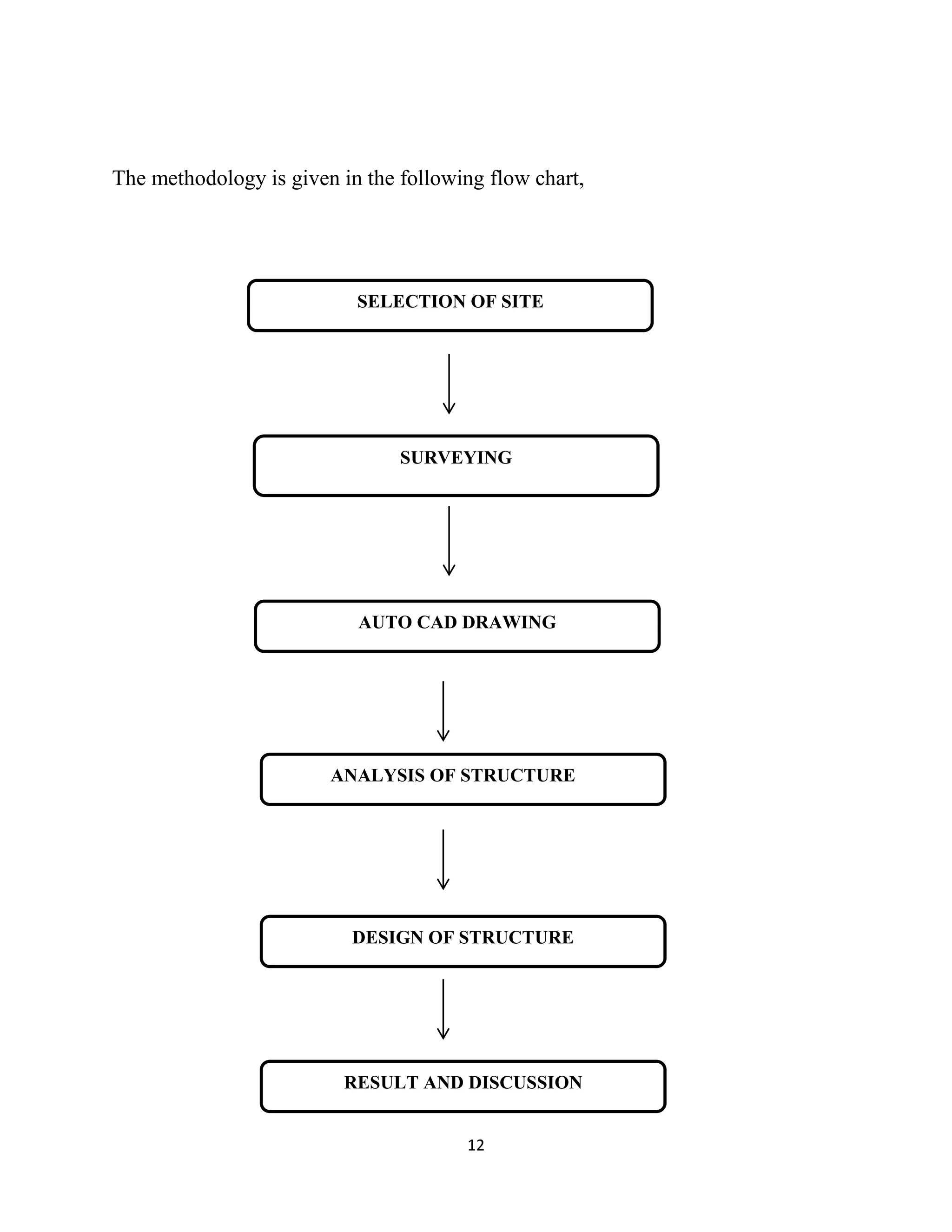
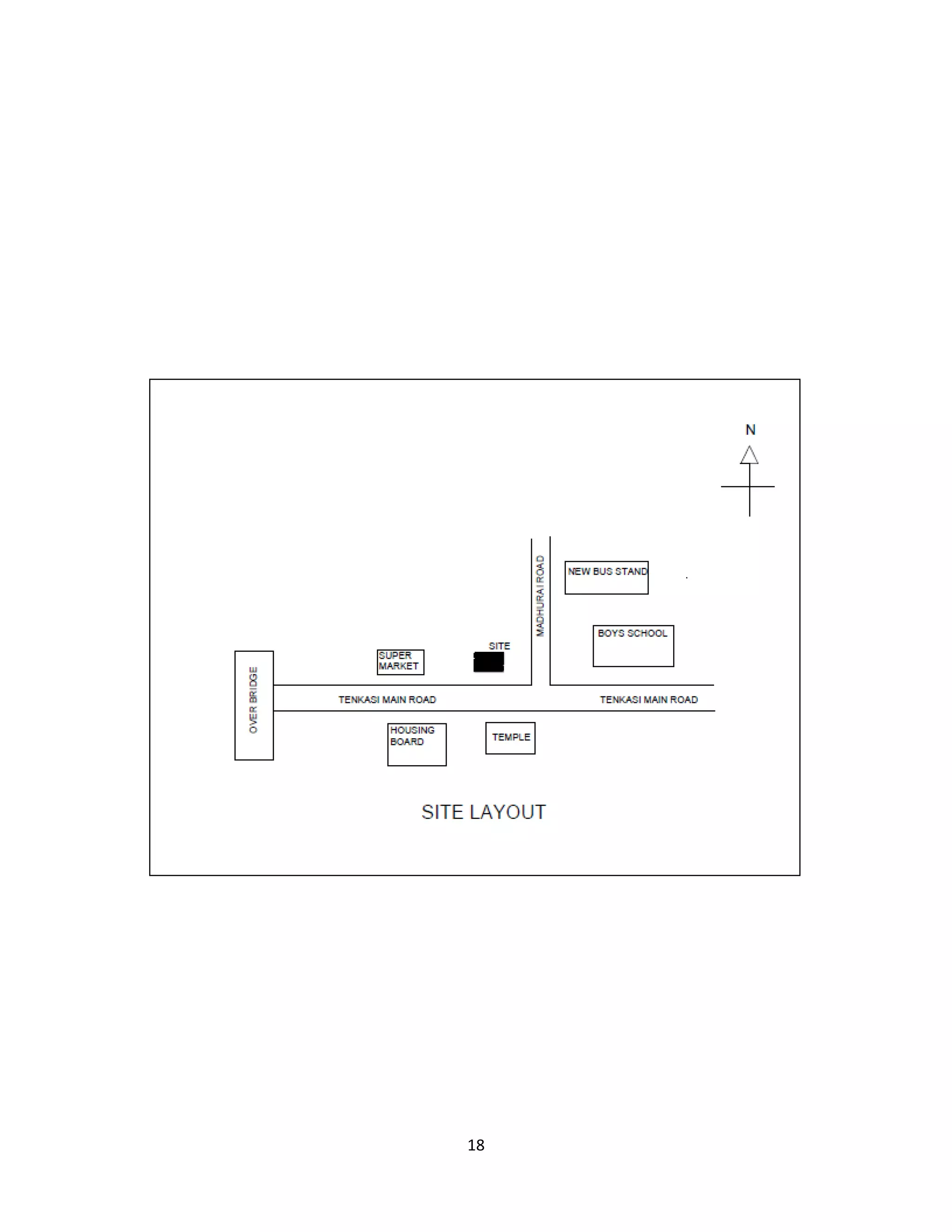
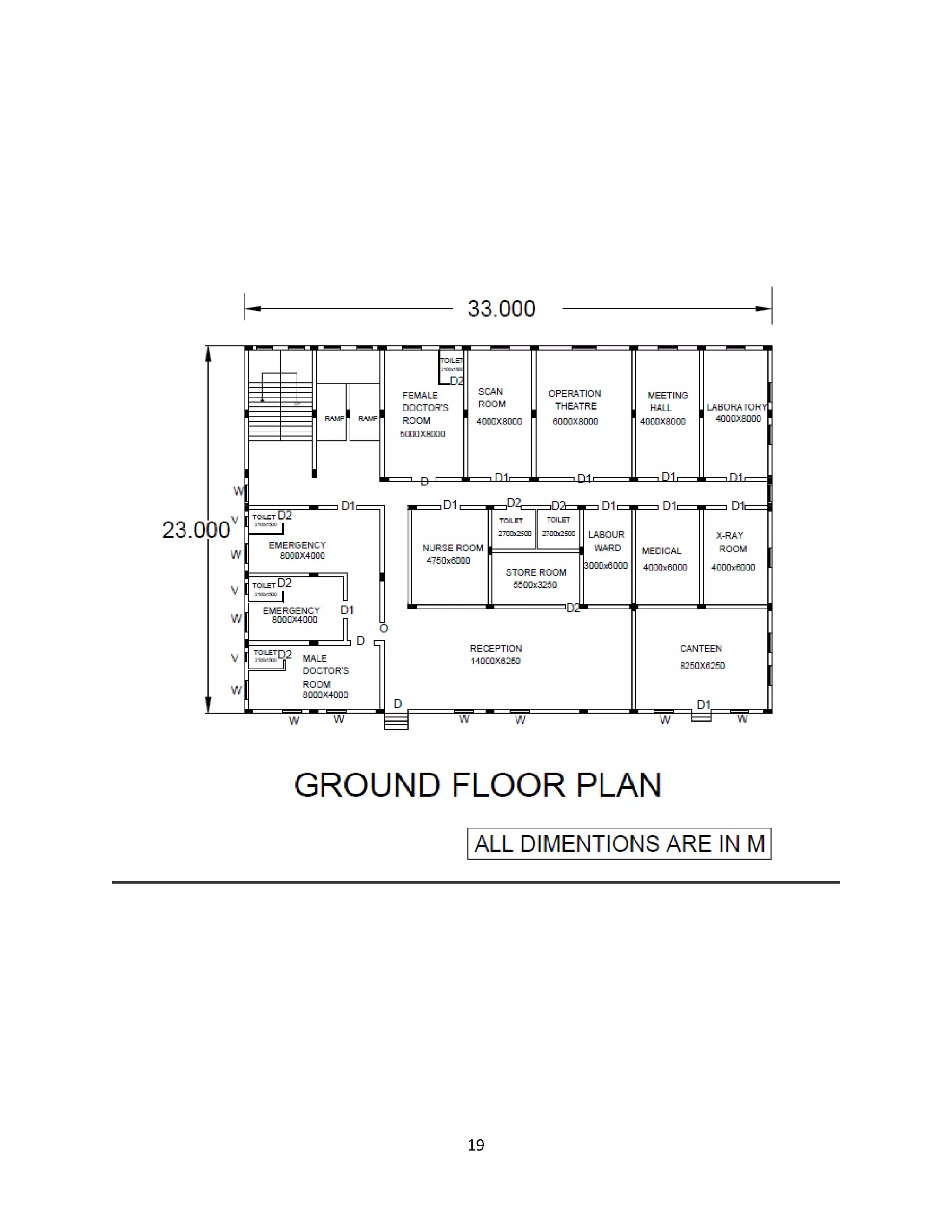
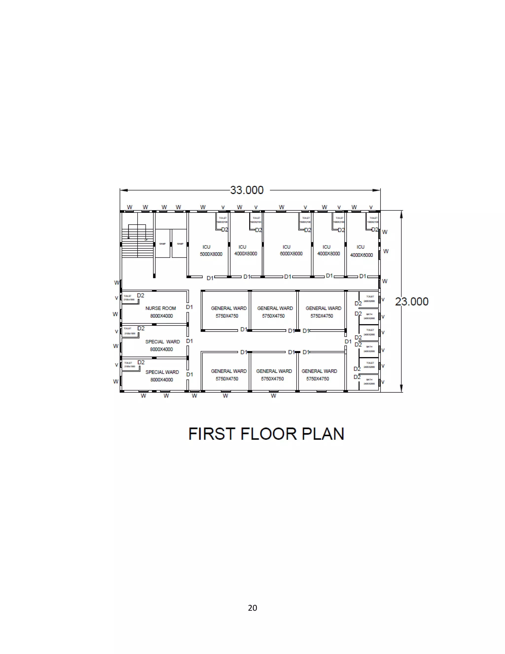
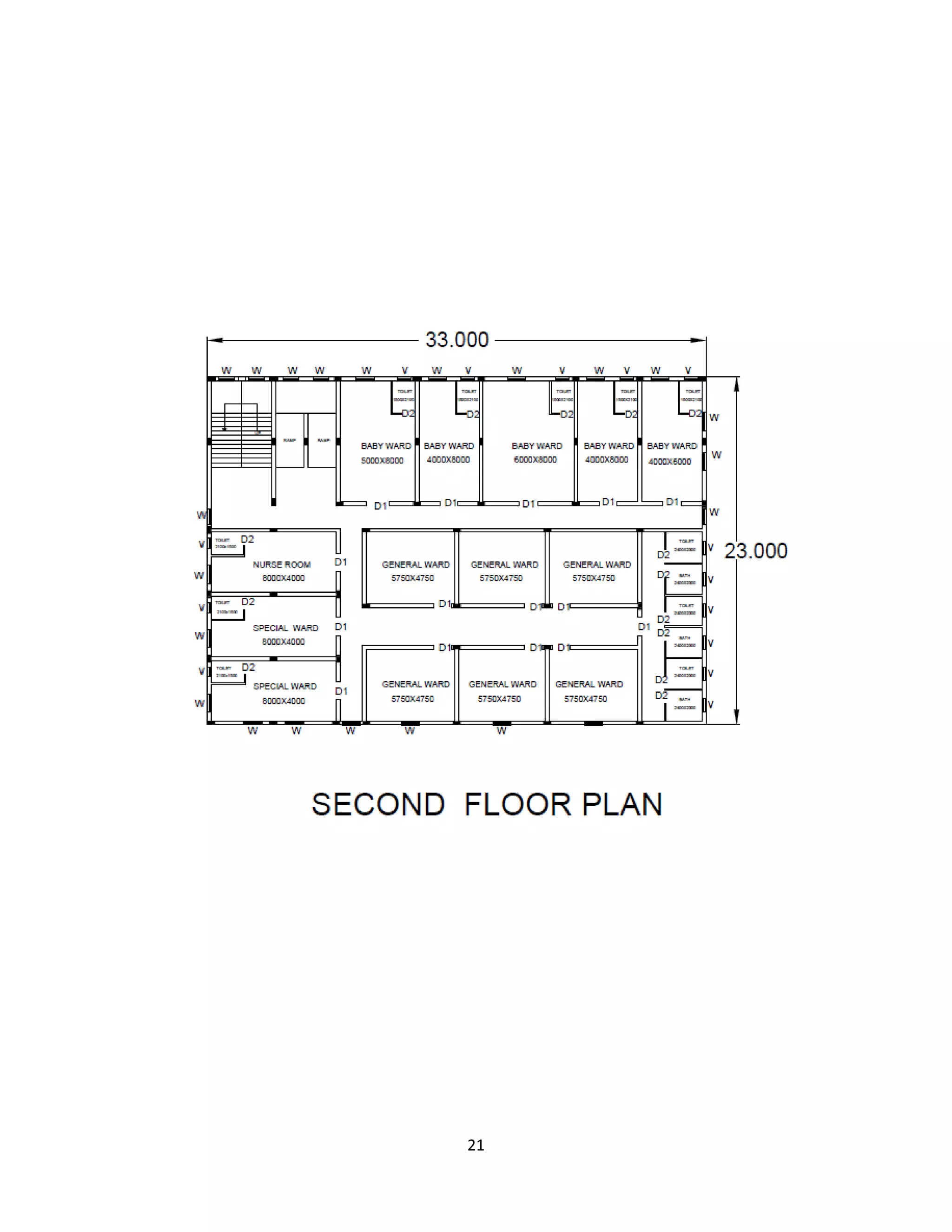
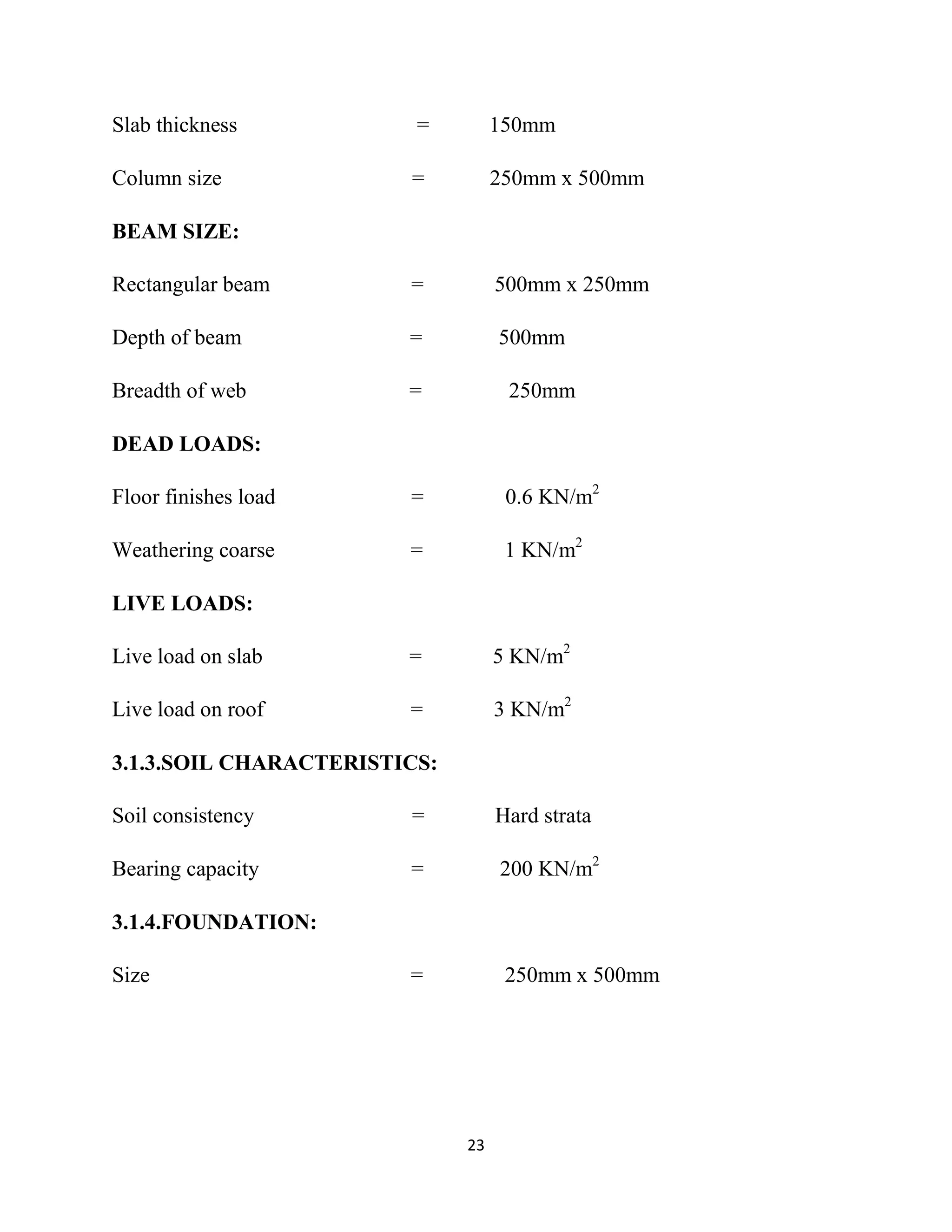
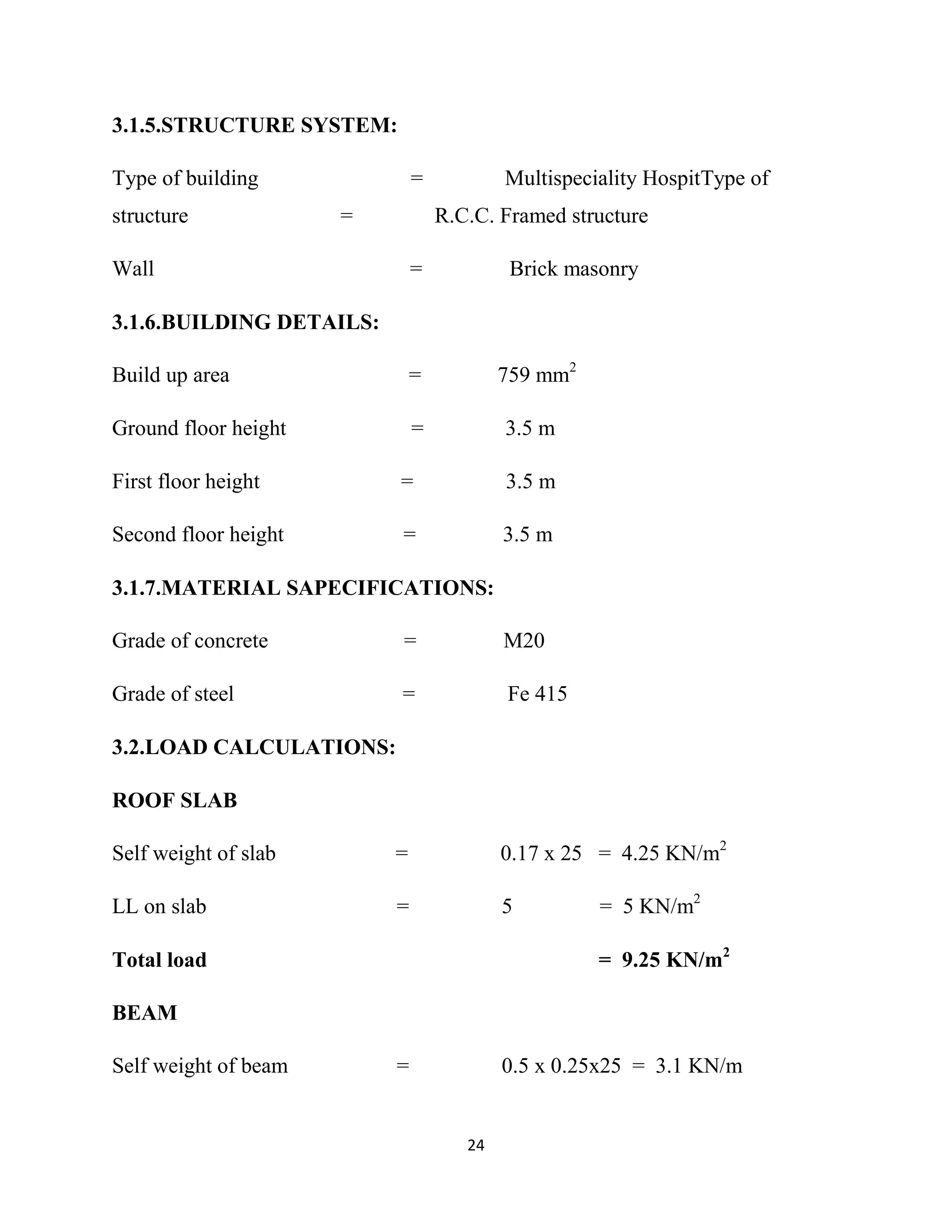
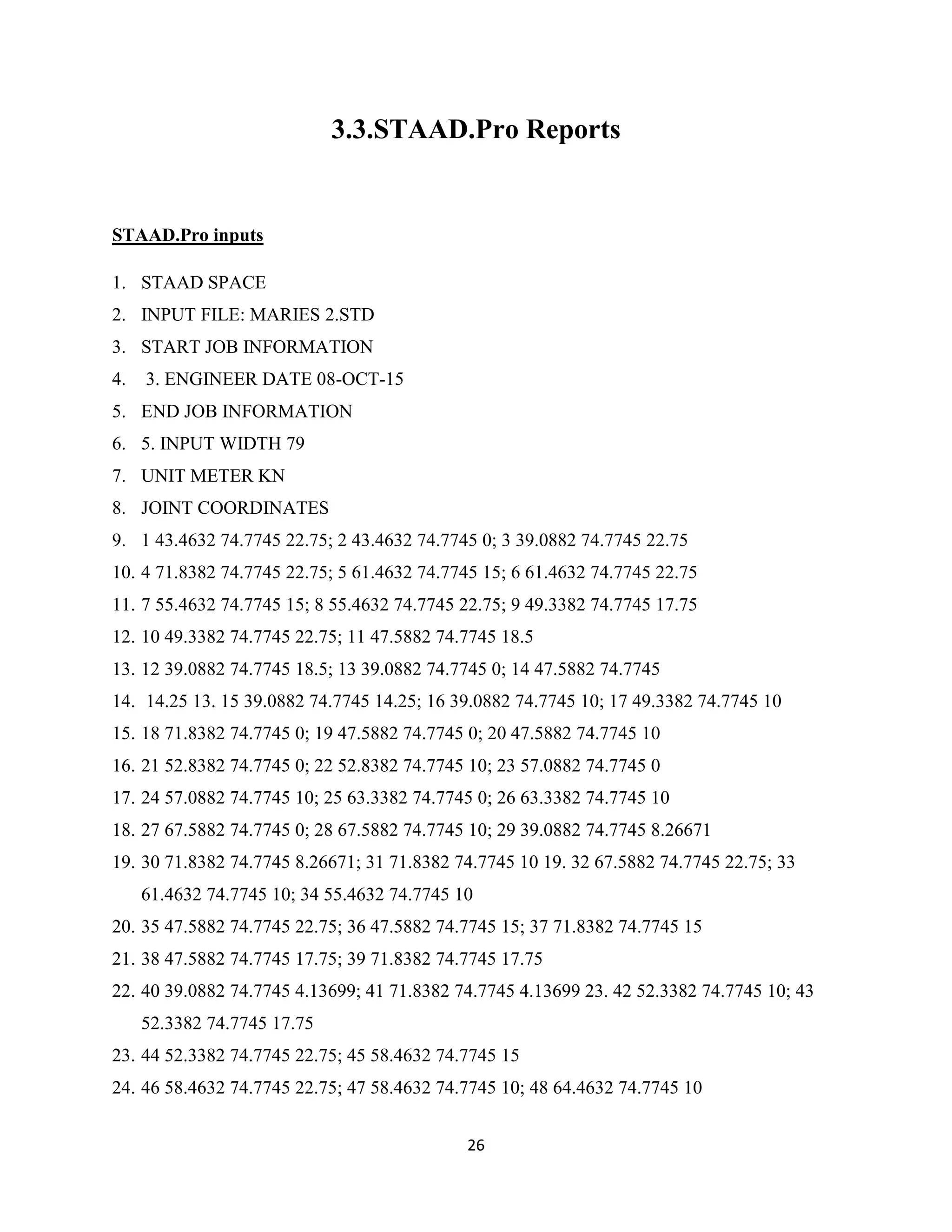
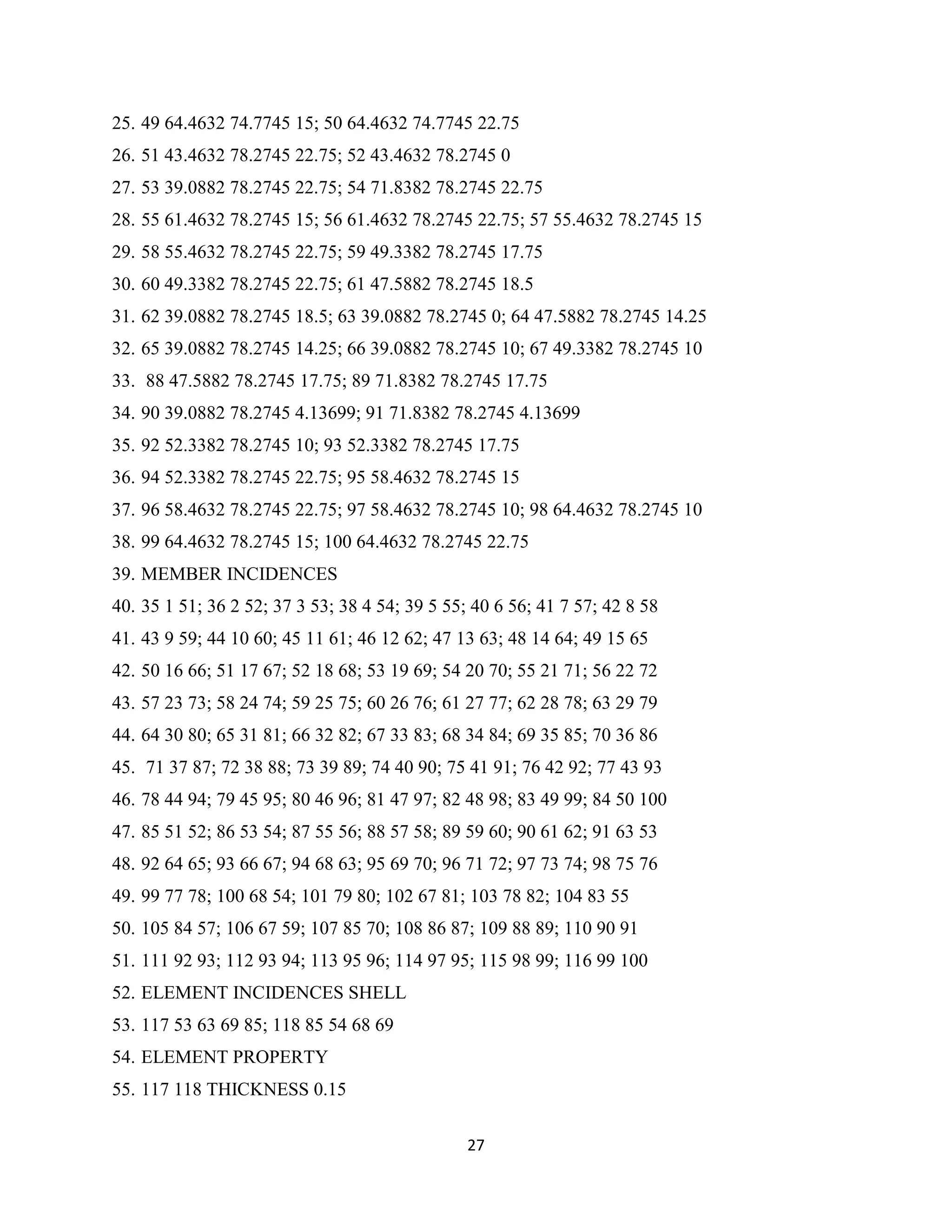
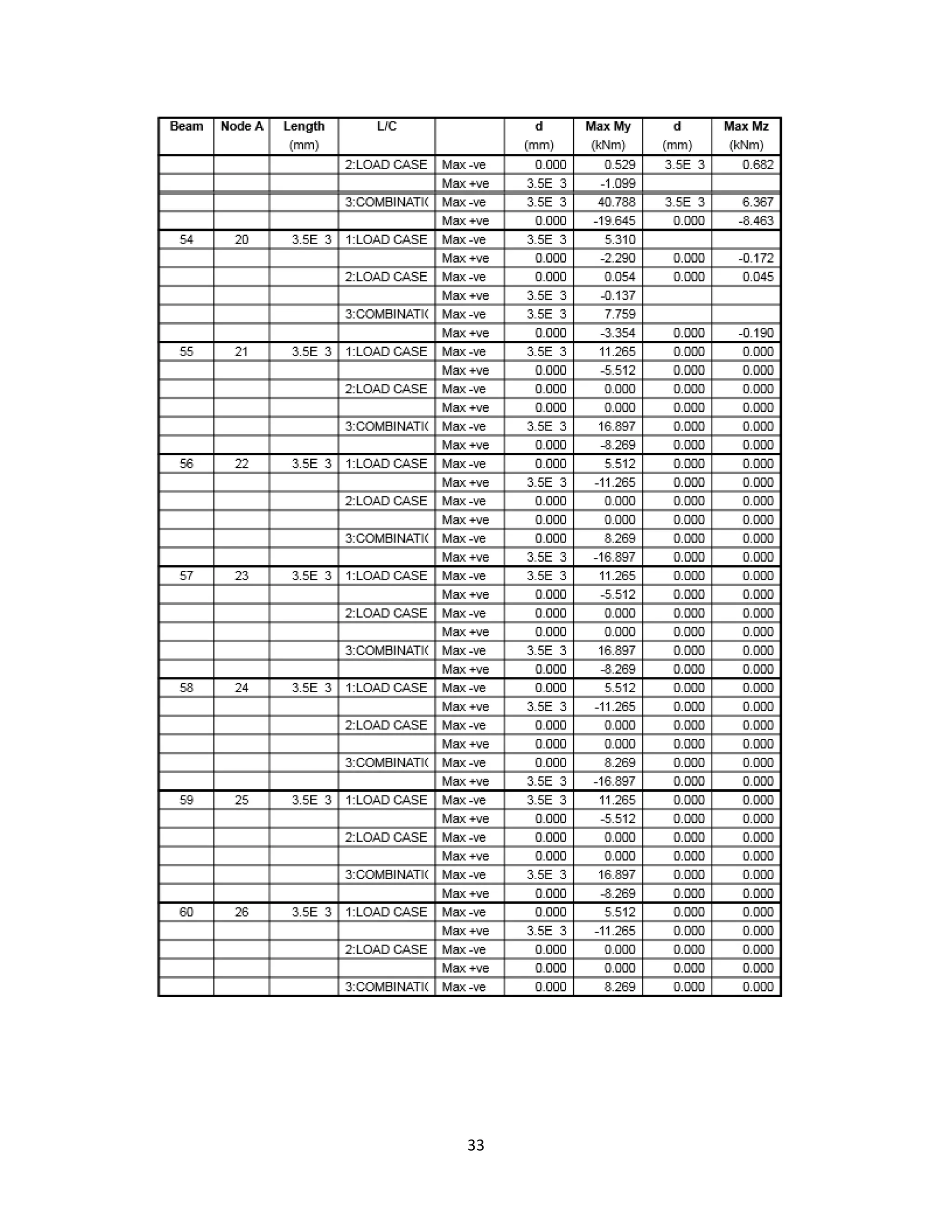
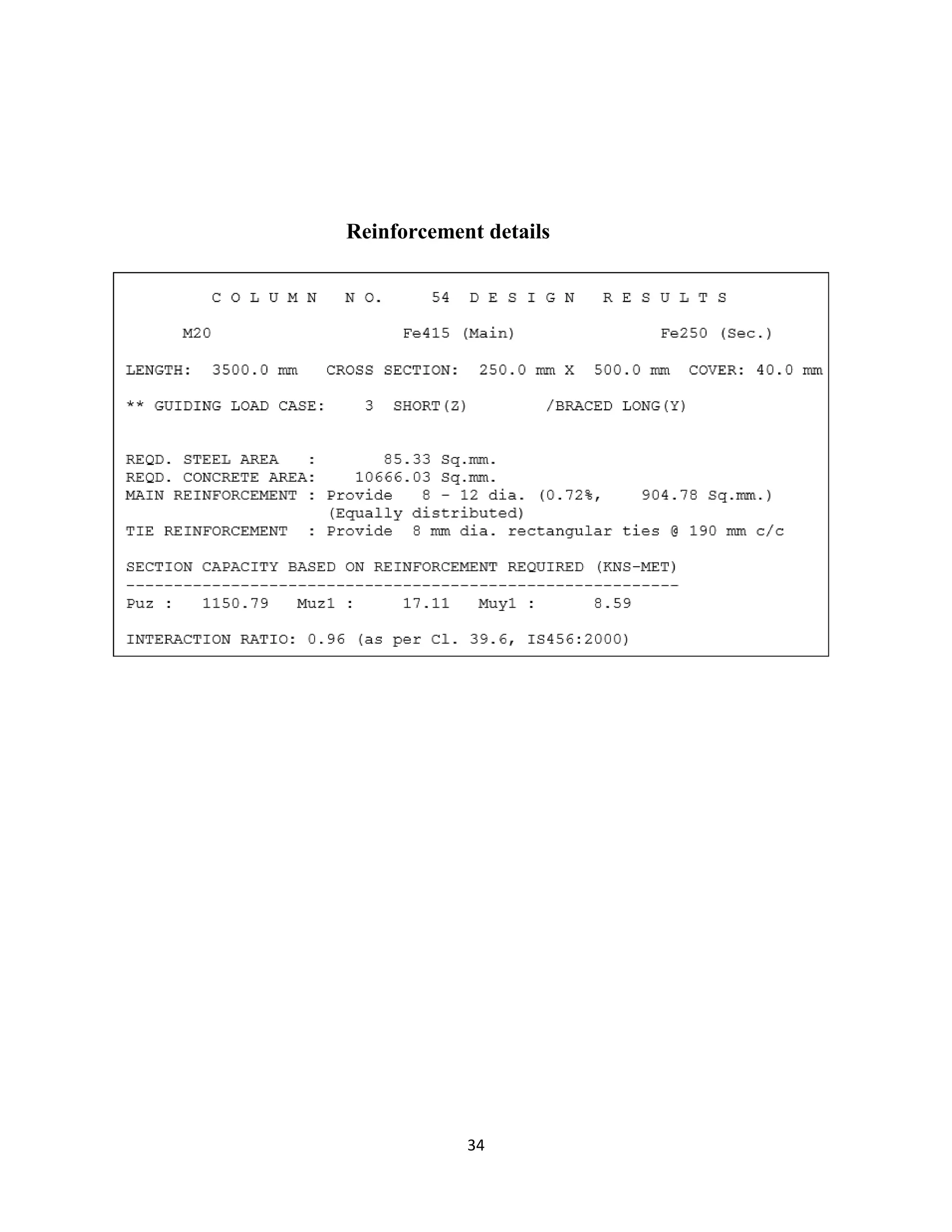
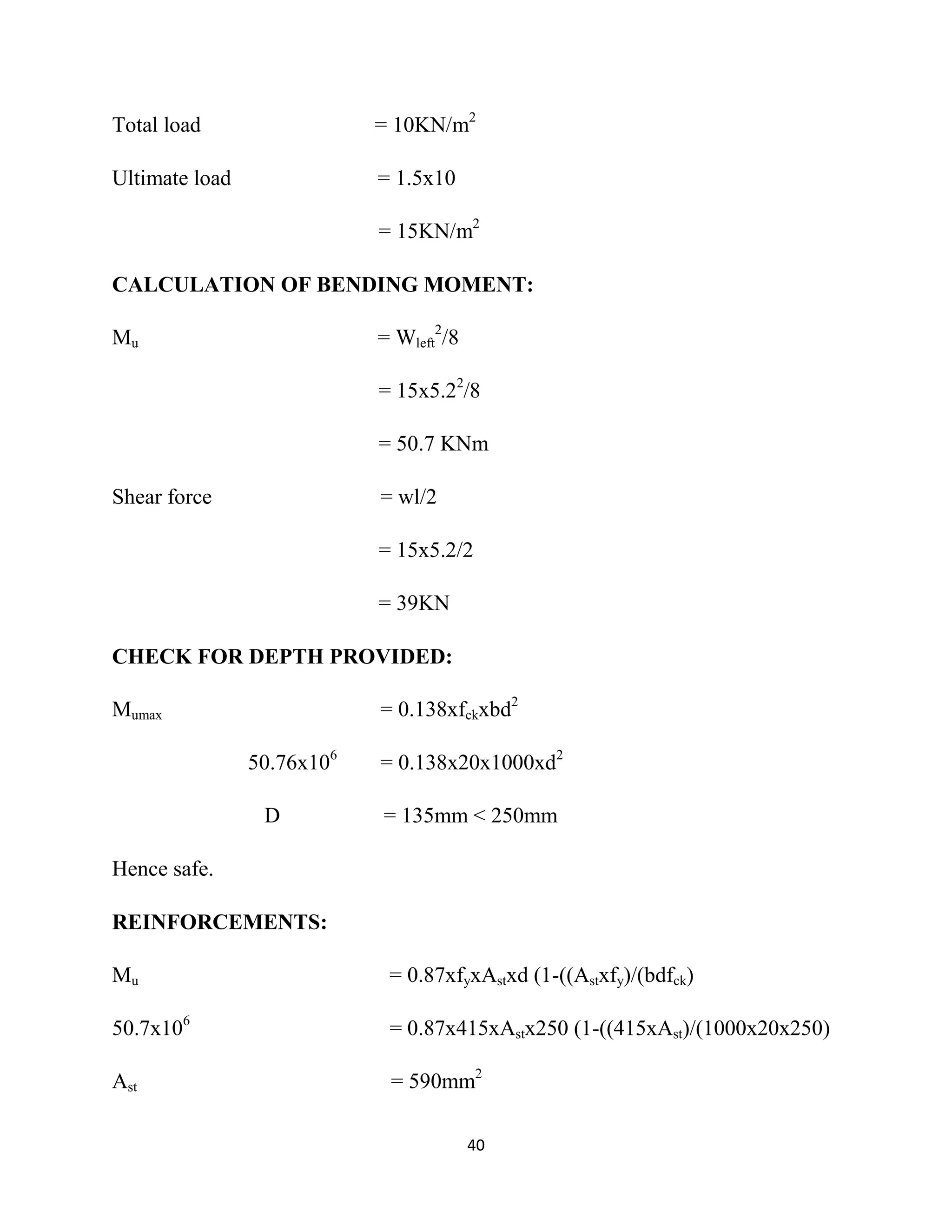
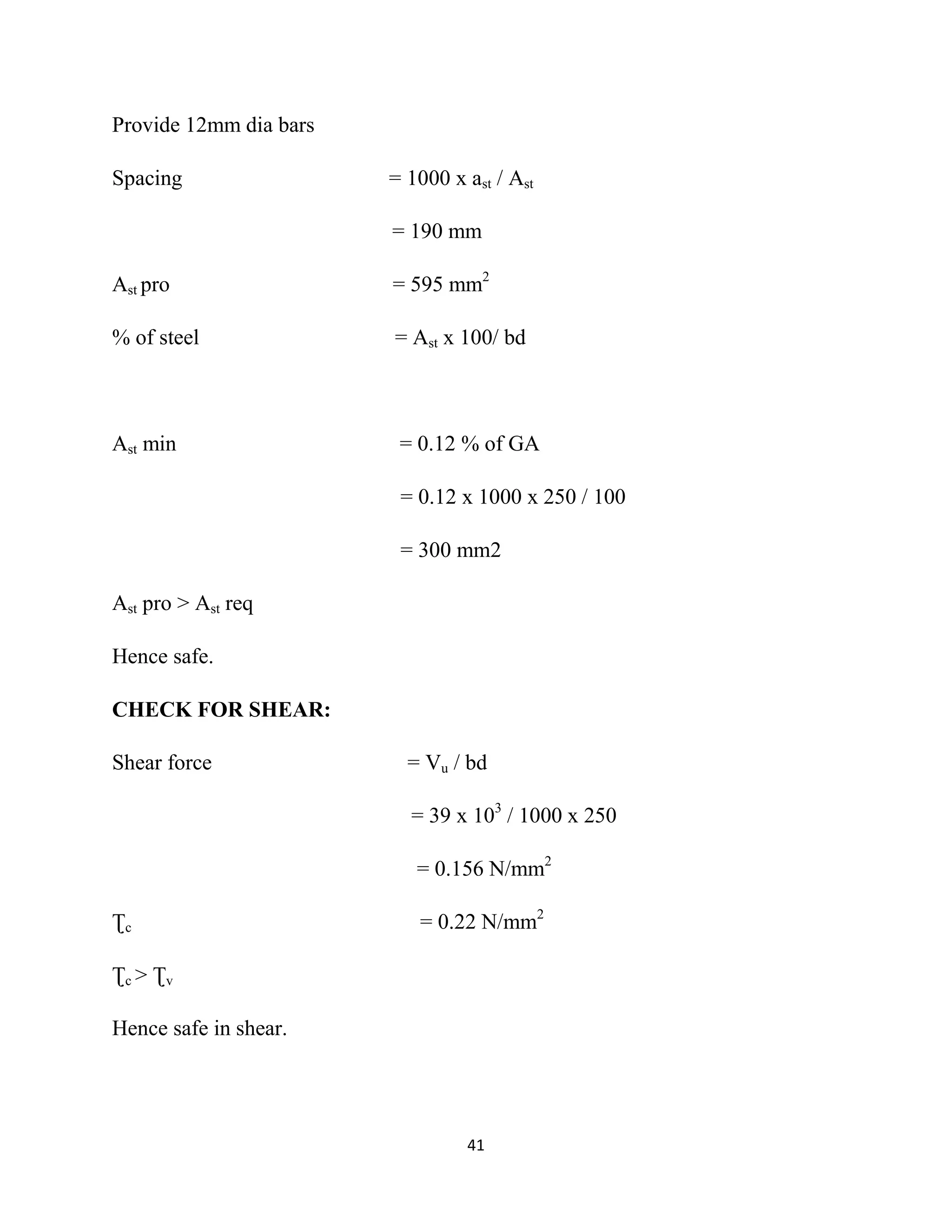
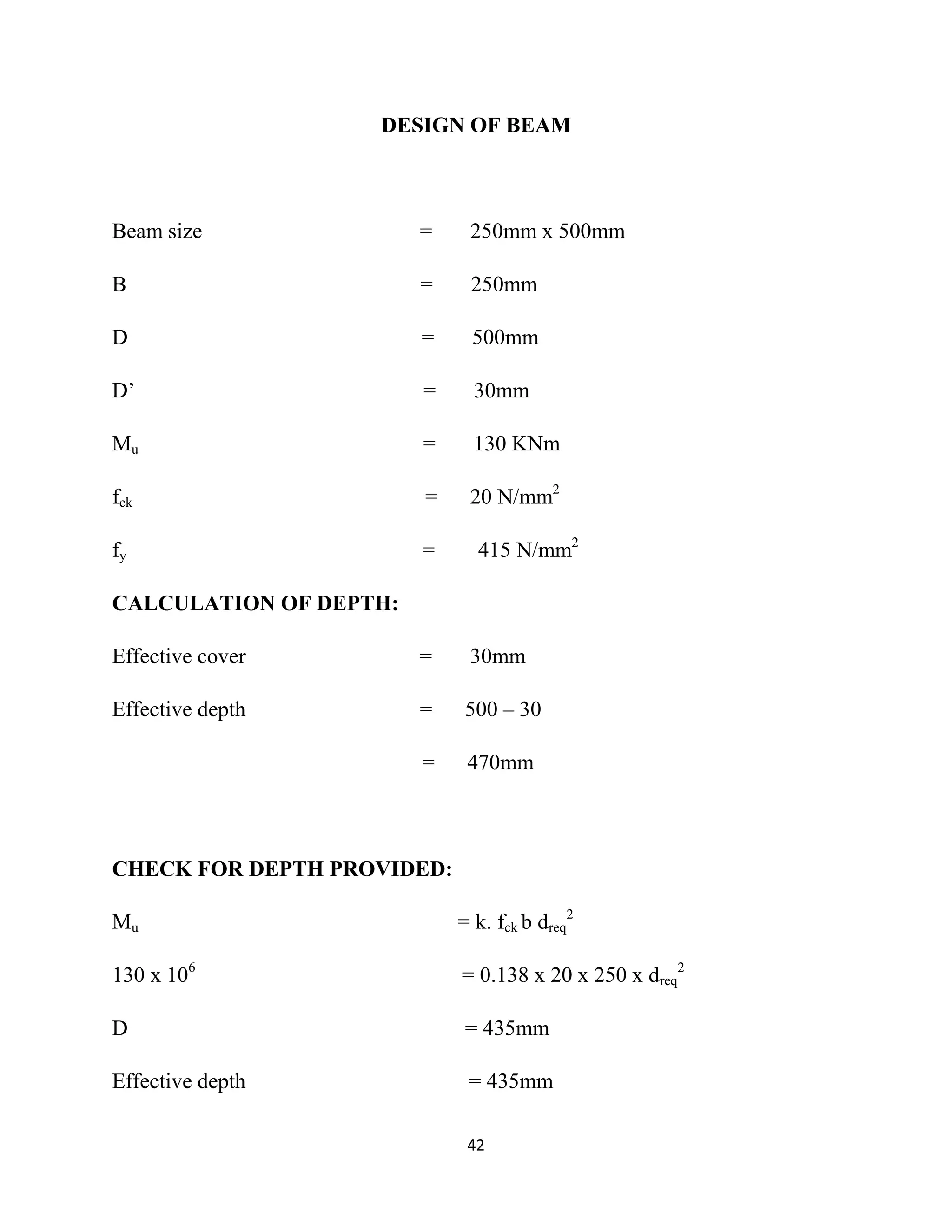
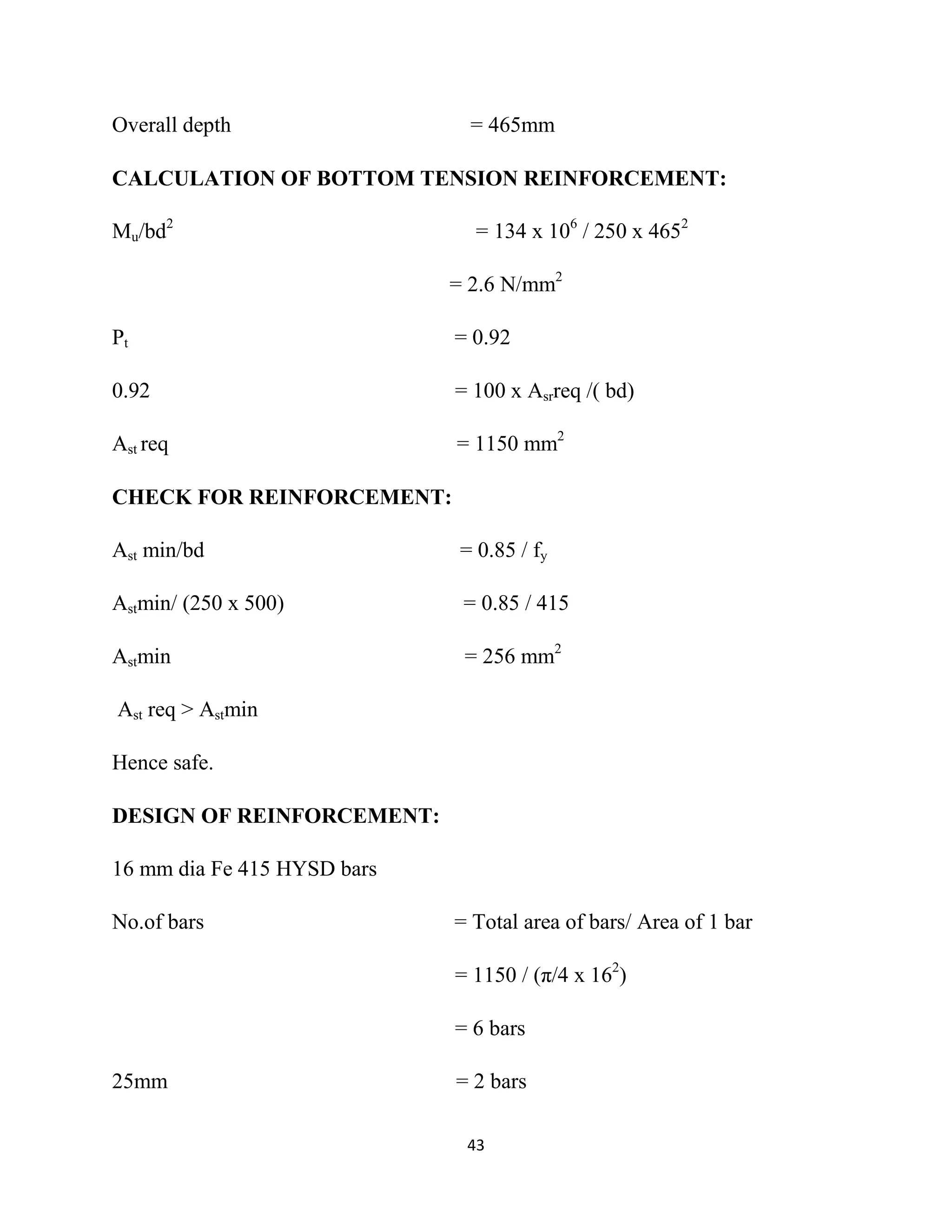
SlideShare a Scribd company logo
1 of 58
Download to read offline
1
PLANNING ANALYSIS AND DESIGN OF
A HOSPITAL BUILDING
A PROJECT REPORT
Submitted by
SASI VIJAYALAKSHMI.T
VIJAYALAKSHMI.K
MARIYAMMAL.S
In partial fulfillment for the award of the degree
Of
BACHELOR OF ENGINEERING
IN
CIVIL ENGINEERING
SREE SOWDAMBIKA COLLEGE OF ENGINEERING,
ARUPPUKOTTAI.
ANNA UNIVERSITY :: CHENNAI 600 025
NOV / DEC - 2015
2
PLANNING ANALYSIS AND DESIGN OF
A HOSPITAL BUILDING
A PROJECT REPORT
Submitted by
SASI VIJAYALAKSHMI.T (921812103036)
VIJAYALAKSHMI.K (921812103055)
MARIYAMMAL.S (921812103307)
In partial fulfillment for the award of the degree
Of
BACHELOR OF ENGINEERING
IN
CIVIL ENGINEERING
SREE SOWDAMBIKA COLLEGE OF ENGINEERING,
ARUPPUKOTTAI.
ANNA UNIVERSITY :: CHENNAI 600 025
NOV / DEC 2015
3
ANNA UNIVERSITY : CHENNAI 600 025
BONAFIDE CERTIFICATE
Certified that this project report “ PLANNING ANALYSIS AND DESIGN OF
A HOSPITAL BUILDING” is the bonafide work of “VIJAYALAKSHMI. K
SASI VIJAYALAKSHMI.T, , MARIYAMMAL.S” who carried out the project
work under my supervision.
SIGNATURE SIGNATURE
Mr. JOHN SURESHKUMAR. M.E., Mrs. D. GAYATHRI. M.E.,
HEAD OF THE DEPARTMENT, PROJECT GUIDE,
Department of Civil Engg., Asst. Professor., (civil)
Sree Sowdambika College of Engg Sree Sowdambika College of Engg
Aruppukottai Aruppukottai
INTERNAL EXAMINER EXTERNAL EXAMINER
4
ACKNOWLEDGEMENT
At the outset I would like to express my praise and gratitude of God Almighty for
his supreme guidance, strength and ways for accomplishing this project
successfully.
I reverently thank the Principal Dr.M.Sivakumar M.Tech.,Ph.D for his prayer.
I highly thankMr.C.John Sureshkumar M.E., Head of the Department, Civil
Engineering, for providing necessary facilities for the successful completion of
this project work.
I sincerely thank Mrs.D.Gayathri M.E., Assistant professor, Department of Civil
Engineering for her guidance and for providing necessary facilities and
encouragements for the successful completion of this project work.
We thank all Assistant professors, Non-teaching staffs of our department, and our
friends who gave encouraged us to complete the project.
Sasi vijayalakshmi.T (921812103036)
Vijayalakshmi.K (921812103055)
Mariyammal.S (921812103307)
5
ABSTRACT
Multispeciality hospital building provides medical service to the people. The main
purpose of our project is satisfies the medical needs of people. In this project we
concerned about the plan, analysis and design of Multispeciality hospital building.The
plan of the hospital building is done by using AUTO CADD software. The analysis of
structures were done by using STAAD.Pro as well as IS 456:2000 Code of practice for
plain and reinforced cement concrete. The design of RCC slab, beam, column, footing
and stair case is based on working stress method as per IS 456:2000 code.
6
INDEX
Tables No List of tables
1 Beam End moment and forces
2 Reinforcement details
Figure No. List of figures
1 Site layout
2 Ground floor plan
3 First floor plan
4 Second floor plan
5 Beam and Column position Diagram
6 Model structure in STAAD.Pro
7 Load application on model structure
8 Bending moment Diagram
9 Shear Force Diagram
10 Displacement diagram of whole structures
11 Reinforcement Details of Footing
12 Reinforcement Details of Column
13 Reinforcement Details of Beam
14 Reinforcement Details of Slab
15 Reinforcement Details of Staircase
7
LIST OF SYMBOLS
Symbols Description Unit
A Cross section area Mm
Ast Area of transverse reinforcement for torsion Mm2
B Breadth of beam Mm
Bp Width of pedestal Mm
D Effective width of span Mm
D’ Effective depth of span Mm
Fck Characteristic compressive strength of concrete N/mm2
Fy Characteristis strength of steel N/mm2
Ftt Allowable tensile stress in concrete initial transfer of
prestress
N/mm2
Fct Allowable compressive stress in concrete initial transfer of
prestress
N/mm2
Finf Prestress in concrete at bottom of section (inferior) N/mm2
G Distributed dead load or acceleration due to gravity KN/m
H Overall depth of section Mm
L Effective span Mm
LL Live load KN/m2
Lp Length of pedestal Mm
M Bending moment KNm
Md Design moment (serviceability limit state) KNm
Mumax Maximum of moment Mux and Muy per meter length at the
face of pedestal
KNm
P Prestressing force N/mm2
Pu Net ultimate upward soil pressure KN
Q Live load KN/m2
Qo Allowable bearing capacity of the soil N/mm2
S Spacing of stirrup links Mm
V Shear force KN
W Distributed load per unit area KN/m2
We Weight of soil KN/m3
Symbols Description Unit
Xu Neutral axis depth Mm
Ʈc Ultimate shear stress in concrete N/mm2
Ʈv Shear stress due to transverse shear N/mm2
8
Ʈuc Shear stress of concrete in footing N/mm2
SL.NO CHAPTER
NO
CONTENTS
Acknowledgement
Abstract
List of Tables
List of Figures
List of Symbols
1 1 Introduction
2 1.1.General
3 1.1.1.Soil investigation
4 1.1.2.Specification of structure
5 1.1.3.Code provisions
6 1.2.Objectives and methodology
7 1.3.Analysis of Framed Structure
8 1.3.1.Method of Analysis
9 1.3.2.Maximum BM in Beams & Columns
10 1.4.Design of RCC Framed Structural Elements
11 1.4.1.Footing
12 1.4.2.Column
13 1.4.3.Beam
14 1.4.4.Slab
15 1.4.5.Staircases
16 2 Plan
17 2.1.Faclilities in Ground floor
18 2.2.Facilities in First, Second & Third floor
19 3 Analysis of Framed Structure
20 3.1.Technical data
21 3.1.1.Loads acting on the Analysis structure
22 3.1.2.Super structure dimensions
23 3.1.3.Soil characteristics
24 3.1.4.Foundation
25 3.1.5.Structural system
26 3.1.6.Building details
27 3.1.7.Material specification
28 3.2.Load calculation
9
29 3.3.STAAD.Pro Reports
30 4 Design of Structural Elements
31 4.1.Design of slab
32 4.2.Design of beams
33 4.3.Design of Columns
34 4.4.Design of Staircase
35 4.5.Design of Footing
36 5 Conclusion
37 6 Bibliography
10
CHAPTER – 1
INTRODUCTION
1.1.GENERAL:
We will propose to construct a Multispeciality hospital building in Tenkasi (near
Tenkasi to Madurai road).
1.1.1.SOIL INVESTIGATION:
The safe bearing capacity of the soil is found as 200 KN/m2
. The depth of the
footing is taken to 1.5m, the rectangular footing is to be designed.
1.1.2.SPECIFICATION OF STRUCTURES:
 The building roof is designed as RCC.
 All the framed structure like column,footing,beam,lintels and roof are
designed in working stress methods and IS 456:2000. Grade of concrete
M20, Grade of steel Fe 415.
 The flooring concrete of plain cement concrete using broken stone will be
finished with marbles.
 All the surface will be plastered and all ceiling areas.
 Weathering coarse will be provided with brick jelly and lime concrete, top
finished with flat tiles.
 All the joineries like doors, windows and ventilators are designed to meet
the standard code provisions.
11
 Lump sum provisions have been made towards the sanitary arrangements,
electrification, elevation and water supply arrangements, supplying and
fixing of furnitures and petty supervision charges.
1.1.3.CODE PROVISIONS:
 IS 456:2000
 NATIONAL BUILDING CODE 1970
1.2.OBJECTIVE AND METHODOLOGY
The objectives of our project are
 To prepare architectural and structural drawings.
 To analysis a Multispeciality hospital building (G+2) storied using
STAAD.Pro
 To design a Multispeciality hospital building is (G+2).
12
The methodology is given in the following flow chart,
SELECTION OF SITE
SURVEYING
AUTO CAD DRAWING
ANALYSIS OF STRUCTURE
DESIGN OF STRUCTURE
RESULT AND DISCUSSION
13
1.3.ANALYSIS OF FRAMED STRUCTURE:
The method by which multispeciality hospital building frames resist horizontal
lateral forces depends upon how the structures has be laid down or planned to bear
these loads.
1.3.2.MAXIMUM BENDING MOMENTS IN BEAMS AND COLUMNS:
The magnitude of bending moments in beams and columns depends upon their
relative rigidity. Generally the beams and columns are made of the same dimension
in alla floors. Beams and columns are made of the same dimension and provided.
1.4.DESIGN OF RCC FRAMED STRUCTURES:
Reinforced cement concrete members can be designed by one of the following
methods.
A) Limit state method.
B) Working stress method.
1.4.B.WORKING STRESS METHOD:
 This is conventional method adopted in the past in the design of R.C.
structures.
 It is based on the elastic theory in which materials, concrert and steel, are
assumed to be stressed well above their elastic limit under the load.
1.4.1.SLABS:
 A slab is a thin flexible member used in floors and roofs of structures to
support the imposed load.
14
 Slabs are the primary members of a structure,which supports the imposed
loads directly on them and transfer the same safely to the supporting
elements such as beams,walls, columns etc.
1.4.2.BEAMS:
 A beam has to be generally designed for the actions such as bending
moments, shear forces and twisting moments developed by the lateral loads.
 The size of the beam is designed considering the maximum bending moment
in it and generally kept uniform throughout its length.
 IS 456 2000 recommends that maximum grade of concrete should not be
less than M25 in R.C. works.
1.4.2.1.BREADTH OF BEAMS:
 It shall not exceed the size of the supports.Generally the breadth of beam is
kept as 1/3 of its depth.
1.4.2.2.DEPTH OF BEAMS:
 The depth of beams is to be designed to satisfy the strength and stiffness
requirements.
 It also satisfies sufficient M.R. and deflection check as recommendeb in
IS 456:2000.
 For preliminary analysis purpose over II depth of beam may assumed to be
1/10 of clear span for simply supported and 1/7 to 1/5 for continuous and
cantilever beam.
1.4.3.COLUMN:
 Members in compression are called are columns or struts.
15
 The term “column” is reserved for members who transfer loads to the
ground.
 The column is classified in two based on the slenderness ratio, they are short
column and long column.
End condition Effective length factor
1.Both end fixed - 0.65L
2.One end fixed, one end hinged - 0.80L
3.Both ends hinged - 1.00L
4.One end fixed other end free - 2.0L
1.4.4.FOOTINGS:
 Foundation is the bottom most important component of a structure.
 It should be well planned and carefully done to ensure the safety and
stability of the strucuture.
 Foundation provided for R.C. column are called columb base.
1.4.4.1.BASIC REQUIREMENTS OF FOOTING:
 It should withstand the applied load moments and induced reactions.
 Sufficient area should be provided according to soil pressure.
1.4.5.STAIRCASES:
16
 Stairway,staircase or simply stairs for a construction designed to bridge a
large vertical distance by dividing it into smaller vertical distances called
steps.
 Stairs may be straight,round, or may consist of two or more straight pieces
connected at angles.
 The step is composed of the tread and riser
TREAD:
It is constructed to the same specifications as any other flooring. The tread depth is
measured from the outer edge of the step to the vertical riser between steps. The
width is measured from one side to the other.
RISER:
The vertical portion between each treads on the stair. This may be missing for an
open stair effect.
17
CHAPTER – 2
PLAN
2.1.FACILITIES IN GROUND FLOOR:
The ground floor consists of scan room emergency ward and ramp facilities are
provided.
2.2.FACILITIES IN FIRST, SECOND & THIRD FLOOR:
The first,second floor consist of intensive care unit, operation theatre and ramp
facilities provided.
18
19
20
21
22
CHAPTER – 3
ANALYSIS OF FRAMED STRUCTURE
The method by which multispeciality hospital building frames resist
horizontal lateral forces depends upon how the structures has be laid down or
planned to bear these loads.
3.1.TECHNICAL DETAILS:
3.1.1.LOADS ACTING ON THE ANALYSIS STRUCTURE:
1.DEAD LOAD:
Self weight = -1KN/m2
2.LIVE LOAD:
For floor slabs = 2 KN/m2
For roof slabs = 1.5 KN/m2
For staircase = 4 KN/m2
3.LOAD COMBINATION:
Load combination = (1.5 D.L) + (1.5 L.L)
3.1.2.SUPER STRUCTURE DIMENSIONS:
Floor wall thickness = 250mm
Parapet wall thickness = 250mm
Parapet wall height = 800mm
23
Slab thickness = 150mm
Column size = 250mm x 500mm
BEAM SIZE:
Rectangular beam = 500mm x 250mm
Depth of beam = 500mm
Breadth of web = 250mm
DEAD LOADS:
Floor finishes load = 0.6 KN/m2
Weathering coarse = 1 KN/m2
LIVE LOADS:
Live load on slab = 5 KN/m2
Live load on roof = 3 KN/m2
3.1.3.SOIL CHARACTERISTICS:
Soil consistency = Hard strata
Bearing capacity = 200 KN/m2
3.1.4.FOUNDATION:
Size = 250mm x 500mm
24
3.1.5.STRUCTURE SYSTEM:
Type of building = Multispeciality HospitType of
structure = R.C.C. Framed structure
Wall = Brick masonry
3.1.6.BUILDING DETAILS:
Build up area = 759 mm2
Ground floor height = 3.5 m
First floor height = 3.5 m
Second floor height = 3.5 m
3.1.7.MATERIAL SAPECIFICATIONS:
Grade of concrete = M20
Grade of steel = Fe 415
3.2.LOAD CALCULATIONS:
ROOF SLAB
Self weight of slab = 0.17 x 25 = 4.25 KN/m2
LL on slab = 5 = 5 KN/m2
Total load = 9.25 KN/m2
BEAM
Self weight of beam = 0.5 x 0.25x25 = 3.1 KN/m
25
B/W wall load = 0.25 x 1x20 = 5 KN/m
Total load = = 8.1 KN/m
26
3.3.STAAD.Pro Reports
STAAD.Pro inputs
1. STAAD SPACE
2. INPUT FILE: MARIES 2.STD
3. START JOB INFORMATION
4. 3. ENGINEER DATE 08-OCT-15
5. END JOB INFORMATION
6. 5. INPUT WIDTH 79
7. UNIT METER KN
8. JOINT COORDINATES
9. 1 43.4632 74.7745 22.75; 2 43.4632 74.7745 0; 3 39.0882 74.7745 22.75
10. 4 71.8382 74.7745 22.75; 5 61.4632 74.7745 15; 6 61.4632 74.7745 22.75
11. 7 55.4632 74.7745 15; 8 55.4632 74.7745 22.75; 9 49.3382 74.7745 17.75
12. 10 49.3382 74.7745 22.75; 11 47.5882 74.7745 18.5
13. 12 39.0882 74.7745 18.5; 13 39.0882 74.7745 0; 14 47.5882 74.7745
14. 14.25 13. 15 39.0882 74.7745 14.25; 16 39.0882 74.7745 10; 17 49.3382 74.7745 10
15. 18 71.8382 74.7745 0; 19 47.5882 74.7745 0; 20 47.5882 74.7745 10
16. 21 52.8382 74.7745 0; 22 52.8382 74.7745 10; 23 57.0882 74.7745 0
17. 24 57.0882 74.7745 10; 25 63.3382 74.7745 0; 26 63.3382 74.7745 10
18. 27 67.5882 74.7745 0; 28 67.5882 74.7745 10; 29 39.0882 74.7745 8.26671
19. 30 71.8382 74.7745 8.26671; 31 71.8382 74.7745 10 19. 32 67.5882 74.7745 22.75; 33
61.4632 74.7745 10; 34 55.4632 74.7745 10
20. 35 47.5882 74.7745 22.75; 36 47.5882 74.7745 15; 37 71.8382 74.7745 15
21. 38 47.5882 74.7745 17.75; 39 71.8382 74.7745 17.75
22. 40 39.0882 74.7745 4.13699; 41 71.8382 74.7745 4.13699 23. 42 52.3382 74.7745 10; 43
52.3382 74.7745 17.75
23. 44 52.3382 74.7745 22.75; 45 58.4632 74.7745 15
24. 46 58.4632 74.7745 22.75; 47 58.4632 74.7745 10; 48 64.4632 74.7745 10
27
25. 49 64.4632 74.7745 15; 50 64.4632 74.7745 22.75
26. 51 43.4632 78.2745 22.75; 52 43.4632 78.2745 0
27. 53 39.0882 78.2745 22.75; 54 71.8382 78.2745 22.75
28. 55 61.4632 78.2745 15; 56 61.4632 78.2745 22.75; 57 55.4632 78.2745 15
29. 58 55.4632 78.2745 22.75; 59 49.3382 78.2745 17.75
30. 60 49.3382 78.2745 22.75; 61 47.5882 78.2745 18.5
31. 62 39.0882 78.2745 18.5; 63 39.0882 78.2745 0; 64 47.5882 78.2745 14.25
32. 65 39.0882 78.2745 14.25; 66 39.0882 78.2745 10; 67 49.3382 78.2745 10
33. 88 47.5882 78.2745 17.75; 89 71.8382 78.2745 17.75
34. 90 39.0882 78.2745 4.13699; 91 71.8382 78.2745 4.13699
35. 92 52.3382 78.2745 10; 93 52.3382 78.2745 17.75
36. 94 52.3382 78.2745 22.75; 95 58.4632 78.2745 15
37. 96 58.4632 78.2745 22.75; 97 58.4632 78.2745 10; 98 64.4632 78.2745 10
38. 99 64.4632 78.2745 15; 100 64.4632 78.2745 22.75
39. MEMBER INCIDENCES
40. 35 1 51; 36 2 52; 37 3 53; 38 4 54; 39 5 55; 40 6 56; 41 7 57; 42 8 58
41. 43 9 59; 44 10 60; 45 11 61; 46 12 62; 47 13 63; 48 14 64; 49 15 65
42. 50 16 66; 51 17 67; 52 18 68; 53 19 69; 54 20 70; 55 21 71; 56 22 72
43. 57 23 73; 58 24 74; 59 25 75; 60 26 76; 61 27 77; 62 28 78; 63 29 79
44. 64 30 80; 65 31 81; 66 32 82; 67 33 83; 68 34 84; 69 35 85; 70 36 86
45. 71 37 87; 72 38 88; 73 39 89; 74 40 90; 75 41 91; 76 42 92; 77 43 93
46. 78 44 94; 79 45 95; 80 46 96; 81 47 97; 82 48 98; 83 49 99; 84 50 100
47. 85 51 52; 86 53 54; 87 55 56; 88 57 58; 89 59 60; 90 61 62; 91 63 53
48. 92 64 65; 93 66 67; 94 68 63; 95 69 70; 96 71 72; 97 73 74; 98 75 76
49. 99 77 78; 100 68 54; 101 79 80; 102 67 81; 103 78 82; 104 83 55
50. 105 84 57; 106 67 59; 107 85 70; 108 86 87; 109 88 89; 110 90 91
51. 111 92 93; 112 93 94; 113 95 96; 114 97 95; 115 98 99; 116 99 100
52. ELEMENT INCIDENCES SHELL
53. 117 53 63 69 85; 118 85 54 68 69
54. ELEMENT PROPERTY
55. 117 118 THICKNESS 0.15
28
56. DEFINE MATERIAL START
57. ISOTROPIC CONCRETE
58. E 2.17185E+007
59. POISSON 0.17
60. DENSITY 23.5616
61. ALPHA 1E-005
62. DAMP 0.05
63. END DEFINE MATERIAL
64. MEMBER PROPERTY
65. 35 TO 84 PRIS YD 0.5 ZD 0.25
66. 85 TO 116 PRIS YD 0.25 ZD 0.25
67. CONSTANTS
68. MATERIAL CONCRETE ALL
69. SUPPORTS
70. 1 TO 50 FIXED
71. LOAD 1 LOADTYPE NONE TITLE LOAD CASE 1.
72. SELFWEIGHT Y -1
73. LOAD 2 LOADTYPE NONE TITLE LOAD CASE 2
74. ELEMENT LOAD
75. 117 118 PR GY -5.5
76. LOAD COMB 3 COMBINATION LOAD CASE 3
77. 1 1.5 2 1.5
78. UNIT MMS NEWTON
79. PERFORM ANALYSIS PRINT ALL
80. FINISH
29
30
31
Beam maximum moments
32
33
34
Reinforcement details
35
CHAPTER – 4
DESIGN OF RC STRUCTURAL MEMBERS
4.1.DESIGN OF SLABS:
4.1.1.DESIGN OF TWO WAY SLAB:
Lx = 5m and LY = 8m
IDENTIFICATION OF SLAB:
LY/LX = 8/5
= 1.6<2
This is two way slab.
CALCULATION OF EFFECTIVE DEPTH:
Span/Effective depth = 20
Effective depth = 5000/20
= 250mm
Cover = 20mm
Overall depth = 270mm
CALCULATION OF LOAD:
Self weight = 0.27x25
= 6.75KN/m2
36
Floor finishes = 0.6KN/m2
Live load = 3KN/m2
Total load = 10KN/m2
Ultimate load = 1.5x10
= 15KN/m2
CALCULATION OF BENDING MOMENT:
Mu = Wleft
2
/8
= 15x5.22
/8
= 50.7 KNm
Shear force = wl/2
= 15x5.2/2
= 39KN
CHECK FOR DEPTH PROVIDED:
Mumax = 0.138xfckxbd2
50.76x106
= 0.138x20x1000xd2
D = 135mm < 250mm
Hence safe.
REINFORCEMENTS:
Mu = 0.87xfyxAstxd (1-((Astxfy)/(bdfck)
37
50.7x106
= 0.87x415xAstx250 (1-((415xAst)/(1000x20x250)
Ast = 590mm2
Provide 12mm dia bars
Spacing = 1000 x ast / Ast
= 190 mm
Ast pro = 595 mm2
% of steel = Ast x 100/ bd
Ast min = 0.12 % of GA
= 0.12 x 1000 x 250 / 100
= 300 mm2
Ast pro > Ast req
Hence safe.
CHECK FOR SHEAR:
Shear force = Vu / bd
= 39 x 103
/ 1000 x 250
= 0.156 N/mm2
Ʈc = 0.22 N/mm2
Ʈc > Ʈv
38
Hence safe in shear.
39
DESIGN OF RAMP SLAB
4.1.2.DESIGN OF TWO WAY SLAB:
Lx = 5m and LY = 8m
IDENTIFICATION OF SLAB:
LY/LX = 8/5
= 1.6<2
This is two way slab.
CALCULATION OF EFFECTIVE DEPTH:
Span/Effective depth = 20
Effective depth = 5000/20
= 250mm
Cover = 20mm
Overall depth = 270mm
CALCULATION OF LOAD:
Self weight = 0.27x25
= 6.75KN/m2
Floor finishes = 0.6KN/m2
Live load = 3KN/m2
40
Total load = 10KN/m2
Ultimate load = 1.5x10
= 15KN/m2
CALCULATION OF BENDING MOMENT:
Mu = Wleft
2
/8
= 15x5.22
/8
= 50.7 KNm
Shear force = wl/2
= 15x5.2/2
= 39KN
CHECK FOR DEPTH PROVIDED:
Mumax = 0.138xfckxbd2
50.76x106
= 0.138x20x1000xd2
D = 135mm < 250mm
Hence safe.
REINFORCEMENTS:
Mu = 0.87xfyxAstxd (1-((Astxfy)/(bdfck)
50.7x106
= 0.87x415xAstx250 (1-((415xAst)/(1000x20x250)
Ast = 590mm2
41
Provide 12mm dia bars
Spacing = 1000 x ast / Ast
= 190 mm
Ast pro = 595 mm2
% of steel = Ast x 100/ bd
Ast min = 0.12 % of GA
= 0.12 x 1000 x 250 / 100
= 300 mm2
Ast pro > Ast req
Hence safe.
CHECK FOR SHEAR:
Shear force = Vu / bd
= 39 x 103
/ 1000 x 250
= 0.156 N/mm2
Ʈc = 0.22 N/mm2
Ʈc > Ʈv
Hence safe in shear.
42
DESIGN OF BEAM
Beam size = 250mm x 500mm
B = 250mm
D = 500mm
D’ = 30mm
Mu = 130 KNm
fck = 20 N/mm2
fy = 415 N/mm2
CALCULATION OF DEPTH:
Effective cover = 30mm
Effective depth = 500 – 30
= 470mm
CHECK FOR DEPTH PROVIDED:
Mu = k. fck b dreq
2
130 x 106
= 0.138 x 20 x 250 x dreq
2
D = 435mm
Effective depth = 435mm
43
Overall depth = 465mm
CALCULATION OF BOTTOM TENSION REINFORCEMENT:
Mu/bd2
= 134 x 106
/ 250 x 4652
= 2.6 N/mm2
Pt = 0.92
0.92 = 100 x Asrreq /( bd)
Ast req = 1150 mm2
CHECK FOR REINFORCEMENT:
Ast min/bd = 0.85 / fy
Astmin/ (250 x 500) = 0.85 / 415
Astmin = 256 mm2
Ast req > Astmin
Hence safe.
DESIGN OF REINFORCEMENT:
16 mm dia Fe 415 HYSD bars
No.of bars = Total area of bars/ Area of 1 bar
= 1150 / (π/4 x 162
)
= 6 bars
25mm = 2 bars
44
Provide 6 #16mm dia Fe 415 bars @ the bottom of the main tension reinforcement
Astpro = N x area of one bar
= 6 x (π/4) x 162
= 1206.37 mm2
Ast pro > Ast req
Hence safe.
NOMINAL REINFORCEMENT AT THE TOP:
Provide 2 # 12 mm dia bars @ the top of the beam. The top of the beam as nominal
bars for stirrups.
CHECK FOR SHEAR:
Shear force in the beam = 85 KN
Ʈv = Vu/bd
= 0.68 N/mm2
100 As/bd = 0.5 N/mm2
Ʈc = 0.3 N/mm2
Ʈc max = 1.8 N/mm2
Ʈv > Ʈc < Ʈc max
45
CHECK FOR DEFLECTION:
L/D max = (L/D) basic x Kt x Kc x Kf
Fs = 0.58 x 415 x (256/1150)
= 53.58
Kt = 1.5
(L/D) provided = 8.6
(L/D) max = 20 x Kt
= 30
(L/D) max > (L/D) provided
Hence safe.
46
DESIGN OF COLUMN
Size = 500mm x 250mm
Length = 4.75 m = 4750 mm
Effective length = 0.8 L
= 0.8 x 4.75
= 3.8 m
CHECK FOR SLENDERNESS RATIO:
Slenderness ratio = Le / b
= 3.8 / 0.5
= 7.6 < 12
Slenderness ratio = Le / d
= 3.8 / 0.25
= 15.2 m
Hence it is a short column.
CALCULATION OF Ag:
Pu = 0.4 fck Ac + 0.67 fy Ast
Ag = 500 x 250 mm2
Axial load = 1250 KN
47
Ultimate load = 1.5 x 1250
= 1875 KN
1875 x 103
= 0.4 x 20 x (12500 – Asc) + ( 0.67 x 415 x Asc)
Asc = 3301.2 mm2
No of bars = 10 nos
Provide 40mm clear cover
Provide 20 mm dia bars @ 100mm
DESIGN OF DISTRIBUTION REINFORCEMENT:
Dist greater of = 1 x 20 / 4
= 5 mm = 6mm dia
6 mm ties are provided
PITCH:
Least lateral dimension = 250 mm
= 16 x dia of bars
= 16 x 20
= 320 mm
Provide 6mm dia bar ties @ 300 mm C/C
48
49
DESIGN OF STAIRCASE
No. of steps in flight = 10
Thread = 300mm
Rise = 150mm
Width of landing beam = 300mm
EFFECTIVE SPAN:
L = ( no. of steps x tread) + width of landing beam)
= ( 10 x 300 ) + 300
= 3300mm
Tk of waist slab = span/20
= 3300/20
= 165mm
LOADS:
D.L of slab on slope, ws = tkx1x25
= 1.65 x 25 x 1
= 4125 KN/m
D.L. on horizontal span, w = ws (T2
+ R2
)1/2
/T
= 4125 ( 3002
+ 1502
)1/2
/300
50
= 4611.8 N/mm
D.L. on one step = ½ x b x h x 25
= ½ x 0.3 x 0.15 x 25
= 0.5625 KN/m
Loads on stesps per m length = D.L. on one step x 1000/T
= 0.5625 x 1000 /300
= 1.875 KN/m
Finishes = 0.6 KN/m
Total D.L. = 4.6 + 1.875 + 0.6
= 7.075 KN/m
Live load = 5 KN/m
Total load = 7.075 + 5
= 12.075 KN/m
Ultimate load = 18.11 KN/m
BENDING MOMENT:
Mu = Wul2
/8
= 18.11 x 3.32
/8
= 24.65 KNm
CHECK FOR DEPTH OF WAIST SLAB:
51
D = ( Mu / (0.138 fck b))1/2
= 94.5 mm
Cover = 20mm
Effective depth = 165 – 20 – 10/2
= 140mm
REINFORCEMENT:
Mu = 0.87xfyxAstxd (1-((Astxfy)/(bdfck)
24.65x106
= 0.87x415xAstx140 (1-((415xAst)/(1000x20x140)
= 529.16 mm2
Provide 12 mm dia bars
Spacing = 1000 x π/4 x 122
/ 529.16
= 220 mm
Dis. Reinforcement = o.12 % of GA
= 0.12 x 1000 x 165 /100
= 198 mm2
Provide 8mm dia bars
Spacing = 1000 x π/4 x 82
/ 198
52
= 250 mm
53
DESIGN OF FOOTING
Footing type = Rectangular type footing
Size of the column = 500mm x 250mm
Axial load = 1250 KN
Safe bearing capacity = 200 KN/m3
Self weight of footing = 125 KN
Total factored load = 1375 KN
Footing area = 1375 / (1.15 x 185)
= 6.46 KN/m2
PROPOTION OF THE FOOTING AREA:
(2.5x ) X 5x = 6.46
12.5x2
= 6.46
X = 0.71
Short side of footing = 2.5 x 0.71
Long side of footing = 5 x 0.71
Rectangular footing = 2m x 4m
SOIL PRESSURE:
Pu = 1250 / (2 x 4)
54
= 156.2 KN/m2
FACTORED BENDING MOMENT:
Bending moment @ short side = 0.5Pul2
= 239.18 KNm
Bending moment @ long side = 0.5pul2
= 59.79 KNm
Projection @ short side = 0.5 (4 – 0.5) = 1.75m
Projection @ long side = 0.5 (2 – 0.25) = 0.875m
DESIGN CONSIDERATION:
Mu = 0.138 fck bd2
D = (Mu / (0.138 fck b)1/2
= 294.76 mm
SHEAR CONSIDERATION:
Vu = 156.2 ( 1275-d)
C = Vu / bd
0.36 = 156.2 (1275 – d) / (1000 x d)
D = 380 mm
Overall depth = 400 mm
REINFORCEMENT IN FOOTING:
LONGER DIRECTION:
Mu = 0.87 fy Ast d (1 – (fyAst /(bd fck)))
55
Ast = 1956 mm2
Provide 16mm dia bars
Spacing = 100 mm
SHORTER DIRECTION:
Mu = 0.87 fy Ast d (1 – (fyAst /(bd fck)))
Ast = 446 mm2
Ration of longer to shorter span = 4/2
= 2
Reinforcement in central band width 2m
= ( 2/ B+1) Ast
= (2/1.5+1)x2x446
= 713.6mm2
Provide 12 mm dia bars
Ast min = 0.12 x 1000 x 400 / 100
= 480 mm2
Spacing = 150 mm
CHECK FOR SHEAR STRESS:
Mu = 156.2 x 0.7
= 109.3 KNm
56
100 x Ast / bd = 100 x 1956 / 1000 x 380
= 0.51
Vu / bd = 109.3 x 10³
/ 1000 x 380
= 0.28 N/mm2
57
CHAPTER – 5
CONCLUSION
 The plan was drawn by Auto – cad 2007
 The analysis of the structure was done by using STAAD – PRO software.
 The structural elements are designed by using working stress method and IS
456 – 2000 code provision
 The design project was helped as to acquire knowledge about the various
analysis and design concept and code provision.
58
CHAPTER – 6
BIBILIOGRAPHY
1. “Design of Reinforced Concrete” by N.Krishnaraju.
2. “Soil Mechanics and Foundation Engineering” by P.C.Punmia.
3. “Prestressed Concrete” by Ramamarutham.

More Related Content

What's hot

Design & Analysis of G+2 Residential Building Using STAAD Pro
Design & Analysis of G+2 Residential Building Using STAAD ProDesign & Analysis of G+2 Residential Building Using STAAD Pro
Design & Analysis of G+2 Residential Building Using STAAD ProPARAS TANEJA
 
Apartment building construction project report
Apartment building construction project reportApartment building construction project report
Apartment building construction project reportHiska Chishi
 
Final ppt on staad pro
Final ppt on staad proFinal ppt on staad pro
Final ppt on staad proSakina Faiz
 
Industrial Training Report of Construction Site in Civil Engineering
Industrial Training Report of Construction Site in Civil EngineeringIndustrial Training Report of Construction Site in Civil Engineering
Industrial Training Report of Construction Site in Civil EngineeringRAVI KUMAR
 
Civil engineering internship report
Civil engineering internship reportCivil engineering internship report
Civil engineering internship reportMd Mohsin Mohsin
 
Analysis and design of multi-storey building using staad.Pro
Analysis and design of multi-storey building using staad.ProAnalysis and design of multi-storey building using staad.Pro
Analysis and design of multi-storey building using staad.Progsharda123
 
SUMMER TRAINING REPORT ON BUILDING CONSTRUCTION
SUMMER TRAINING REPORT ON BUILDING CONSTRUCTIONSUMMER TRAINING REPORT ON BUILDING CONSTRUCTION
SUMMER TRAINING REPORT ON BUILDING CONSTRUCTIONVed Jangid
 
Design of residential building
Design of residential buildingDesign of residential building
Design of residential buildingK.MAHESH KUMAR
 
Analysis and design of building
Analysis and design of buildingAnalysis and design of building
Analysis and design of buildingKrishnagnr
 
Civil enginerring internship report
Civil enginerring internship reportCivil enginerring internship report
Civil enginerring internship reportZahid Khan
 
Design and analasys of a g+3 residential building using staad
Design and analasys of a g+3 residential building using staadDesign and analasys of a g+3 residential building using staad
Design and analasys of a g+3 residential building using staadgopichand's
 
Design of residential building
Design of residential buildingDesign of residential building
Design of residential buildingK.MAHESH KUMAR
 
DESIGN AND ANALAYSIS OF MULTI STOREY BUILDING USING STAAD PRO
DESIGN AND ANALAYSIS OF MULTI STOREY BUILDING USING STAAD PRODESIGN AND ANALAYSIS OF MULTI STOREY BUILDING USING STAAD PRO
DESIGN AND ANALAYSIS OF MULTI STOREY BUILDING USING STAAD PROAli Meer
 
CIVIL ENGINEERING INTERNSHIP FULL REPORT ON BUILDING CONSTRUCTION
CIVIL ENGINEERING INTERNSHIP FULL REPORT ON BUILDING CONSTRUCTION CIVIL ENGINEERING INTERNSHIP FULL REPORT ON BUILDING CONSTRUCTION
CIVIL ENGINEERING INTERNSHIP FULL REPORT ON BUILDING CONSTRUCTION L&W BUILDING SOLUTIONS PVT. LMT.
 
PROJECT REPORT ON DESIGN OF A RESIDENTIAL BUILDING
PROJECT REPORT ON DESIGN OF A RESIDENTIAL BUILDINGPROJECT REPORT ON DESIGN OF A RESIDENTIAL BUILDING
PROJECT REPORT ON DESIGN OF A RESIDENTIAL BUILDINGAmritpal Singh
 
Summer Internship Report of Civil Engineering in Construction Site
Summer Internship Report of Civil Engineering in Construction SiteSummer Internship Report of Civil Engineering in Construction Site
Summer Internship Report of Civil Engineering in Construction SiteRAVI KUMAR
 
Estimating and-costing book
Estimating and-costing bookEstimating and-costing book
Estimating and-costing bookThomas Britto
 

What's hot (20)

Design of columns as per IS 456-2000
Design of columns as per IS 456-2000Design of columns as per IS 456-2000
Design of columns as per IS 456-2000
 
Design & Analysis of G+2 Residential Building Using STAAD Pro
Design & Analysis of G+2 Residential Building Using STAAD ProDesign & Analysis of G+2 Residential Building Using STAAD Pro
Design & Analysis of G+2 Residential Building Using STAAD Pro
 
Apartment building construction project report
Apartment building construction project reportApartment building construction project report
Apartment building construction project report
 
Design and analasys of a g+2 residential building
Design and analasys of a g+2 residential building Design and analasys of a g+2 residential building
Design and analasys of a g+2 residential building
 
Project
ProjectProject
Project
 
Final ppt on staad pro
Final ppt on staad proFinal ppt on staad pro
Final ppt on staad pro
 
Industrial Training Report of Construction Site in Civil Engineering
Industrial Training Report of Construction Site in Civil EngineeringIndustrial Training Report of Construction Site in Civil Engineering
Industrial Training Report of Construction Site in Civil Engineering
 
Civil engineering internship report
Civil engineering internship reportCivil engineering internship report
Civil engineering internship report
 
Analysis and design of multi-storey building using staad.Pro
Analysis and design of multi-storey building using staad.ProAnalysis and design of multi-storey building using staad.Pro
Analysis and design of multi-storey building using staad.Pro
 
SUMMER TRAINING REPORT ON BUILDING CONSTRUCTION
SUMMER TRAINING REPORT ON BUILDING CONSTRUCTIONSUMMER TRAINING REPORT ON BUILDING CONSTRUCTION
SUMMER TRAINING REPORT ON BUILDING CONSTRUCTION
 
Design of residential building
Design of residential buildingDesign of residential building
Design of residential building
 
Analysis and design of building
Analysis and design of buildingAnalysis and design of building
Analysis and design of building
 
Civil enginerring internship report
Civil enginerring internship reportCivil enginerring internship report
Civil enginerring internship report
 
Design and analasys of a g+3 residential building using staad
Design and analasys of a g+3 residential building using staadDesign and analasys of a g+3 residential building using staad
Design and analasys of a g+3 residential building using staad
 
Design of residential building
Design of residential buildingDesign of residential building
Design of residential building
 
DESIGN AND ANALAYSIS OF MULTI STOREY BUILDING USING STAAD PRO
DESIGN AND ANALAYSIS OF MULTI STOREY BUILDING USING STAAD PRODESIGN AND ANALAYSIS OF MULTI STOREY BUILDING USING STAAD PRO
DESIGN AND ANALAYSIS OF MULTI STOREY BUILDING USING STAAD PRO
 
CIVIL ENGINEERING INTERNSHIP FULL REPORT ON BUILDING CONSTRUCTION
CIVIL ENGINEERING INTERNSHIP FULL REPORT ON BUILDING CONSTRUCTION CIVIL ENGINEERING INTERNSHIP FULL REPORT ON BUILDING CONSTRUCTION
CIVIL ENGINEERING INTERNSHIP FULL REPORT ON BUILDING CONSTRUCTION
 
PROJECT REPORT ON DESIGN OF A RESIDENTIAL BUILDING
PROJECT REPORT ON DESIGN OF A RESIDENTIAL BUILDINGPROJECT REPORT ON DESIGN OF A RESIDENTIAL BUILDING
PROJECT REPORT ON DESIGN OF A RESIDENTIAL BUILDING
 
Summer Internship Report of Civil Engineering in Construction Site
Summer Internship Report of Civil Engineering in Construction SiteSummer Internship Report of Civil Engineering in Construction Site
Summer Internship Report of Civil Engineering in Construction Site
 
Estimating and-costing book
Estimating and-costing bookEstimating and-costing book
Estimating and-costing book
 

Viewers also liked

Design and Analysis of Ladies Hostel using STAAD PRO
Design and Analysis of Ladies Hostel using STAAD PRODesign and Analysis of Ladies Hostel using STAAD PRO
Design and Analysis of Ladies Hostel using STAAD PROMohamed Athif Sultan
 
DESIGN OF HOSTEL BUILDING G+5
DESIGN OF HOSTEL BUILDING G+5DESIGN OF HOSTEL BUILDING G+5
DESIGN OF HOSTEL BUILDING G+5anvesh reddy
 
Intelligent building project report
Intelligent building project reportIntelligent building project report
Intelligent building project reportBeing Deepak
 
G+3 APARTMENT BUILDING PROJECT REPORT
G+3 APARTMENT BUILDING  PROJECT  REPORTG+3 APARTMENT BUILDING  PROJECT  REPORT
G+3 APARTMENT BUILDING PROJECT REPORTFresher Thinking
 
A project report on shopping mall
A project report on shopping mallA project report on shopping mall
A project report on shopping malltivar rose
 
Hospital project report
Hospital project reportHospital project report
Hospital project reportjssclinic
 

Viewers also liked (7)

Design and Analysis of Ladies Hostel using STAAD PRO
Design and Analysis of Ladies Hostel using STAAD PRODesign and Analysis of Ladies Hostel using STAAD PRO
Design and Analysis of Ladies Hostel using STAAD PRO
 
DESIGN OF HOSTEL BUILDING G+5
DESIGN OF HOSTEL BUILDING G+5DESIGN OF HOSTEL BUILDING G+5
DESIGN OF HOSTEL BUILDING G+5
 
Intelligent building project report
Intelligent building project reportIntelligent building project report
Intelligent building project report
 
G+3 APARTMENT BUILDING PROJECT REPORT
G+3 APARTMENT BUILDING  PROJECT  REPORTG+3 APARTMENT BUILDING  PROJECT  REPORT
G+3 APARTMENT BUILDING PROJECT REPORT
 
A project report on shopping mall
A project report on shopping mallA project report on shopping mall
A project report on shopping mall
 
Shopping mall
Shopping mallShopping mall
Shopping mall
 
Hospital project report
Hospital project reportHospital project report
Hospital project report
 

Similar to Hospital building project

Analysis and Design of G+3 shopping complex
Analysis and Design of G+3 shopping complexAnalysis and Design of G+3 shopping complex
Analysis and Design of G+3 shopping complexDhananjay Singh
 
IRJET- Structural Analysis and Design of Pump House
IRJET- Structural Analysis and Design of Pump HouseIRJET- Structural Analysis and Design of Pump House
IRJET- Structural Analysis and Design of Pump HouseIRJET Journal
 
Effect of Positioning and Configuration of Shear Walls on Seismic Performance...
Effect of Positioning and Configuration of Shear Walls on Seismic Performance...Effect of Positioning and Configuration of Shear Walls on Seismic Performance...
Effect of Positioning and Configuration of Shear Walls on Seismic Performance...IRJET Journal
 
IMPROVING THE STRUCTURAL EFFICIENCY OF STEEL TRUSSES BY COMPARATIVE STUDY
IMPROVING THE STRUCTURAL EFFICIENCY OF STEEL TRUSSES BY COMPARATIVE STUDYIMPROVING THE STRUCTURAL EFFICIENCY OF STEEL TRUSSES BY COMPARATIVE STUDY
IMPROVING THE STRUCTURAL EFFICIENCY OF STEEL TRUSSES BY COMPARATIVE STUDYIRJET Journal
 
Optimisation of earth quake response of tall building by using different fram...
Optimisation of earth quake response of tall building by using different fram...Optimisation of earth quake response of tall building by using different fram...
Optimisation of earth quake response of tall building by using different fram...eSAT Journals
 
Design and analysis for supporting system of circular ESR for different seism...
Design and analysis for supporting system of circular ESR for different seism...Design and analysis for supporting system of circular ESR for different seism...
Design and analysis for supporting system of circular ESR for different seism...IRJET Journal
 
Group 2 , ce471
Group 2  ,  ce471Group 2  ,  ce471
Group 2 , ce471ktx500
 
Study on Concentric Steel Bracing at Soft Storey During Earthquake
Study on Concentric Steel Bracing at Soft Storey During EarthquakeStudy on Concentric Steel Bracing at Soft Storey During Earthquake
Study on Concentric Steel Bracing at Soft Storey During EarthquakeIRJET Journal
 
IRJET- Dynamic Analysis of Tall Tubular Steel Structures for Different Geomet...
IRJET- Dynamic Analysis of Tall Tubular Steel Structures for Different Geomet...IRJET- Dynamic Analysis of Tall Tubular Steel Structures for Different Geomet...
IRJET- Dynamic Analysis of Tall Tubular Steel Structures for Different Geomet...IRJET Journal
 
Modelling Analysis and Design of Self Anchored Suspension Bridge
Modelling Analysis and Design of Self Anchored Suspension BridgeModelling Analysis and Design of Self Anchored Suspension Bridge
Modelling Analysis and Design of Self Anchored Suspension BridgeRohit Grandhi, EIT
 
IRJET- Analysis and Design of High-Rise RC Structure in Different Seismic Zones
IRJET- Analysis and Design of High-Rise RC Structure in Different Seismic ZonesIRJET- Analysis and Design of High-Rise RC Structure in Different Seismic Zones
IRJET- Analysis and Design of High-Rise RC Structure in Different Seismic ZonesIRJET Journal
 
finalprojectreportg2-141218075116-conversion-gate01 (1).pdf
finalprojectreportg2-141218075116-conversion-gate01 (1).pdffinalprojectreportg2-141218075116-conversion-gate01 (1).pdf
finalprojectreportg2-141218075116-conversion-gate01 (1).pdfAbdurRazzak187410
 
IRJET - Dynamic Analysis of Steel Truss Bridge under Various Combinational Mo...
IRJET - Dynamic Analysis of Steel Truss Bridge under Various Combinational Mo...IRJET - Dynamic Analysis of Steel Truss Bridge under Various Combinational Mo...
IRJET - Dynamic Analysis of Steel Truss Bridge under Various Combinational Mo...IRJET Journal
 
579040435-Mini-Project-Analysis-of-Residential-Building-Using-ETABS.pdf
579040435-Mini-Project-Analysis-of-Residential-Building-Using-ETABS.pdf579040435-Mini-Project-Analysis-of-Residential-Building-Using-ETABS.pdf
579040435-Mini-Project-Analysis-of-Residential-Building-Using-ETABS.pdfDivyashreeBM1
 
IRJET- Study of Response of Wall Type Pier for Varying Width of Superstru...
IRJET-  	  Study of Response of Wall Type Pier for Varying Width of Superstru...IRJET-  	  Study of Response of Wall Type Pier for Varying Width of Superstru...
IRJET- Study of Response of Wall Type Pier for Varying Width of Superstru...IRJET Journal
 
Seismic evelution of rc space frame with rectangular and equivalent square co...
Seismic evelution of rc space frame with rectangular and equivalent square co...Seismic evelution of rc space frame with rectangular and equivalent square co...
Seismic evelution of rc space frame with rectangular and equivalent square co...eSAT Publishing House
 
State of the Art and Practice Geotechnical Design
State of the Art and Practice Geotechnical DesignState of the Art and Practice Geotechnical Design
State of the Art and Practice Geotechnical DesignDr Mazin Alhamrany
 
B.Tech Research Paper
B.Tech Research PaperB.Tech Research Paper
B.Tech Research PaperLahari Prabha
 

Similar to Hospital building project (20)

Analysis and Design of G+3 shopping complex
Analysis and Design of G+3 shopping complexAnalysis and Design of G+3 shopping complex
Analysis and Design of G+3 shopping complex
 
IRJET- Structural Analysis and Design of Pump House
IRJET- Structural Analysis and Design of Pump HouseIRJET- Structural Analysis and Design of Pump House
IRJET- Structural Analysis and Design of Pump House
 
Effect of Positioning and Configuration of Shear Walls on Seismic Performance...
Effect of Positioning and Configuration of Shear Walls on Seismic Performance...Effect of Positioning and Configuration of Shear Walls on Seismic Performance...
Effect of Positioning and Configuration of Shear Walls on Seismic Performance...
 
IMPROVING THE STRUCTURAL EFFICIENCY OF STEEL TRUSSES BY COMPARATIVE STUDY
IMPROVING THE STRUCTURAL EFFICIENCY OF STEEL TRUSSES BY COMPARATIVE STUDYIMPROVING THE STRUCTURAL EFFICIENCY OF STEEL TRUSSES BY COMPARATIVE STUDY
IMPROVING THE STRUCTURAL EFFICIENCY OF STEEL TRUSSES BY COMPARATIVE STUDY
 
uni arc
uni arcuni arc
uni arc
 
Optimisation of earth quake response of tall building by using different fram...
Optimisation of earth quake response of tall building by using different fram...Optimisation of earth quake response of tall building by using different fram...
Optimisation of earth quake response of tall building by using different fram...
 
Design and analysis for supporting system of circular ESR for different seism...
Design and analysis for supporting system of circular ESR for different seism...Design and analysis for supporting system of circular ESR for different seism...
Design and analysis for supporting system of circular ESR for different seism...
 
Group 2 , ce471
Group 2  ,  ce471Group 2  ,  ce471
Group 2 , ce471
 
Study on Concentric Steel Bracing at Soft Storey During Earthquake
Study on Concentric Steel Bracing at Soft Storey During EarthquakeStudy on Concentric Steel Bracing at Soft Storey During Earthquake
Study on Concentric Steel Bracing at Soft Storey During Earthquake
 
IRJET- Dynamic Analysis of Tall Tubular Steel Structures for Different Geomet...
IRJET- Dynamic Analysis of Tall Tubular Steel Structures for Different Geomet...IRJET- Dynamic Analysis of Tall Tubular Steel Structures for Different Geomet...
IRJET- Dynamic Analysis of Tall Tubular Steel Structures for Different Geomet...
 
Modelling Analysis and Design of Self Anchored Suspension Bridge
Modelling Analysis and Design of Self Anchored Suspension BridgeModelling Analysis and Design of Self Anchored Suspension Bridge
Modelling Analysis and Design of Self Anchored Suspension Bridge
 
IRJET- Analysis and Design of High-Rise RC Structure in Different Seismic Zones
IRJET- Analysis and Design of High-Rise RC Structure in Different Seismic ZonesIRJET- Analysis and Design of High-Rise RC Structure in Different Seismic Zones
IRJET- Analysis and Design of High-Rise RC Structure in Different Seismic Zones
 
finalprojectreportg2-141218075116-conversion-gate01 (1).pdf
finalprojectreportg2-141218075116-conversion-gate01 (1).pdffinalprojectreportg2-141218075116-conversion-gate01 (1).pdf
finalprojectreportg2-141218075116-conversion-gate01 (1).pdf
 
IRJET - Dynamic Analysis of Steel Truss Bridge under Various Combinational Mo...
IRJET - Dynamic Analysis of Steel Truss Bridge under Various Combinational Mo...IRJET - Dynamic Analysis of Steel Truss Bridge under Various Combinational Mo...
IRJET - Dynamic Analysis of Steel Truss Bridge under Various Combinational Mo...
 
579040435-Mini-Project-Analysis-of-Residential-Building-Using-ETABS.pdf
579040435-Mini-Project-Analysis-of-Residential-Building-Using-ETABS.pdf579040435-Mini-Project-Analysis-of-Residential-Building-Using-ETABS.pdf
579040435-Mini-Project-Analysis-of-Residential-Building-Using-ETABS.pdf
 
IRJET- Study of Response of Wall Type Pier for Varying Width of Superstru...
IRJET-  	  Study of Response of Wall Type Pier for Varying Width of Superstru...IRJET-  	  Study of Response of Wall Type Pier for Varying Width of Superstru...
IRJET- Study of Response of Wall Type Pier for Varying Width of Superstru...
 
Seismic evelution of rc space frame with rectangular and equivalent square co...
Seismic evelution of rc space frame with rectangular and equivalent square co...Seismic evelution of rc space frame with rectangular and equivalent square co...
Seismic evelution of rc space frame with rectangular and equivalent square co...
 
State of the Art and Practice Geotechnical Design
State of the Art and Practice Geotechnical DesignState of the Art and Practice Geotechnical Design
State of the Art and Practice Geotechnical Design
 
B.Tech Research Paper
B.Tech Research PaperB.Tech Research Paper
B.Tech Research Paper
 
Ijciet 10 01_009
Ijciet 10 01_009Ijciet 10 01_009
Ijciet 10 01_009
 

Recently uploaded

Architect Hassan Khalil Portfolio for 2024
Architect Hassan Khalil Portfolio for 2024Architect Hassan Khalil Portfolio for 2024
Architect Hassan Khalil Portfolio for 2024hassan khalil
 
Heart Disease Prediction using machine learning.pptx
Heart Disease Prediction using machine learning.pptxHeart Disease Prediction using machine learning.pptx
Heart Disease Prediction using machine learning.pptxPoojaBan
 
Microscopic Analysis of Ceramic Materials.pptx
Microscopic Analysis of Ceramic Materials.pptxMicroscopic Analysis of Ceramic Materials.pptx
Microscopic Analysis of Ceramic Materials.pptxpurnimasatapathy1234
 
ZXCTN 5804 / ZTE PTN / ZTE POTN / ZTE 5804 PTN / ZTE POTN 5804 ( 100/200 GE Z...
ZXCTN 5804 / ZTE PTN / ZTE POTN / ZTE 5804 PTN / ZTE POTN 5804 ( 100/200 GE Z...ZXCTN 5804 / ZTE PTN / ZTE POTN / ZTE 5804 PTN / ZTE POTN 5804 ( 100/200 GE Z...
ZXCTN 5804 / ZTE PTN / ZTE POTN / ZTE 5804 PTN / ZTE POTN 5804 ( 100/200 GE Z...ZTE
 
GDSC ASEB Gen AI study jams presentation
GDSC ASEB Gen AI study jams presentationGDSC ASEB Gen AI study jams presentation
GDSC ASEB Gen AI study jams presentationGDSCAESB
 
Call Girls Delhi {Jodhpur} 9711199012 high profile service
Call Girls Delhi {Jodhpur} 9711199012 high profile serviceCall Girls Delhi {Jodhpur} 9711199012 high profile service
Call Girls Delhi {Jodhpur} 9711199012 high profile servicerehmti665
 
Artificial-Intelligence-in-Electronics (K).pptx
Artificial-Intelligence-in-Electronics (K).pptxArtificial-Intelligence-in-Electronics (K).pptx
Artificial-Intelligence-in-Electronics (K).pptxbritheesh05
 
IVE Industry Focused Event - Defence Sector 2024
IVE Industry Focused Event - Defence Sector 2024IVE Industry Focused Event - Defence Sector 2024
IVE Industry Focused Event - Defence Sector 2024Mark Billinghurst
 
Internship report on mechanical engineering
Internship report on mechanical engineeringInternship report on mechanical engineering
Internship report on mechanical engineeringmalavadedarshan25
 
chaitra-1.pptx fake news detection using machine learning
chaitra-1.pptx  fake news detection using machine learningchaitra-1.pptx  fake news detection using machine learning
chaitra-1.pptx fake news detection using machine learningmisbanausheenparvam
 
Sheet Pile Wall Design and Construction: A Practical Guide for Civil Engineer...
Sheet Pile Wall Design and Construction: A Practical Guide for Civil Engineer...Sheet Pile Wall Design and Construction: A Practical Guide for Civil Engineer...
Sheet Pile Wall Design and Construction: A Practical Guide for Civil Engineer...Dr.Costas Sachpazis
 
CCS355 Neural Network & Deep Learning Unit II Notes with Question bank .pdf
CCS355 Neural Network & Deep Learning Unit II Notes with Question bank .pdfCCS355 Neural Network & Deep Learning Unit II Notes with Question bank .pdf
CCS355 Neural Network & Deep Learning Unit II Notes with Question bank .pdfAsst.prof M.Gokilavani
 
Model Call Girl in Narela Delhi reach out to us at 🔝8264348440🔝
Model Call Girl in Narela Delhi reach out to us at 🔝8264348440🔝Model Call Girl in Narela Delhi reach out to us at 🔝8264348440🔝
Model Call Girl in Narela Delhi reach out to us at 🔝8264348440🔝soniya singh
 
Oxy acetylene welding presentation note.
Oxy acetylene welding presentation note.Oxy acetylene welding presentation note.
Oxy acetylene welding presentation note.eptoze12
 
High Profile Call Girls Nagpur Meera Call 7001035870 Meet With Nagpur Escorts
High Profile Call Girls Nagpur Meera Call 7001035870 Meet With Nagpur EscortsHigh Profile Call Girls Nagpur Meera Call 7001035870 Meet With Nagpur Escorts
High Profile Call Girls Nagpur Meera Call 7001035870 Meet With Nagpur EscortsCall Girls in Nagpur High Profile
 
main PPT.pptx of girls hostel security using rfid
main PPT.pptx of girls hostel security using rfidmain PPT.pptx of girls hostel security using rfid
main PPT.pptx of girls hostel security using rfidNikhilNagaraju
 
SPICE PARK APR2024 ( 6,793 SPICE Models )
SPICE PARK APR2024 ( 6,793 SPICE Models )SPICE PARK APR2024 ( 6,793 SPICE Models )
SPICE PARK APR2024 ( 6,793 SPICE Models )Tsuyoshi Horigome
 

Recently uploaded (20)

🔝9953056974🔝!!-YOUNG call girls in Rajendra Nagar Escort rvice Shot 2000 nigh...
🔝9953056974🔝!!-YOUNG call girls in Rajendra Nagar Escort rvice Shot 2000 nigh...🔝9953056974🔝!!-YOUNG call girls in Rajendra Nagar Escort rvice Shot 2000 nigh...
🔝9953056974🔝!!-YOUNG call girls in Rajendra Nagar Escort rvice Shot 2000 nigh...
 
★ CALL US 9953330565 ( HOT Young Call Girls In Badarpur delhi NCR
★ CALL US 9953330565 ( HOT Young Call Girls In Badarpur delhi NCR★ CALL US 9953330565 ( HOT Young Call Girls In Badarpur delhi NCR
★ CALL US 9953330565 ( HOT Young Call Girls In Badarpur delhi NCR
 
young call girls in Rajiv Chowk🔝 9953056974 🔝 Delhi escort Service
young call girls in Rajiv Chowk🔝 9953056974 🔝 Delhi escort Serviceyoung call girls in Rajiv Chowk🔝 9953056974 🔝 Delhi escort Service
young call girls in Rajiv Chowk🔝 9953056974 🔝 Delhi escort Service
 
Architect Hassan Khalil Portfolio for 2024
Architect Hassan Khalil Portfolio for 2024Architect Hassan Khalil Portfolio for 2024
Architect Hassan Khalil Portfolio for 2024
 
Heart Disease Prediction using machine learning.pptx
Heart Disease Prediction using machine learning.pptxHeart Disease Prediction using machine learning.pptx
Heart Disease Prediction using machine learning.pptx
 
Microscopic Analysis of Ceramic Materials.pptx
Microscopic Analysis of Ceramic Materials.pptxMicroscopic Analysis of Ceramic Materials.pptx
Microscopic Analysis of Ceramic Materials.pptx
 
ZXCTN 5804 / ZTE PTN / ZTE POTN / ZTE 5804 PTN / ZTE POTN 5804 ( 100/200 GE Z...
ZXCTN 5804 / ZTE PTN / ZTE POTN / ZTE 5804 PTN / ZTE POTN 5804 ( 100/200 GE Z...ZXCTN 5804 / ZTE PTN / ZTE POTN / ZTE 5804 PTN / ZTE POTN 5804 ( 100/200 GE Z...
ZXCTN 5804 / ZTE PTN / ZTE POTN / ZTE 5804 PTN / ZTE POTN 5804 ( 100/200 GE Z...
 
GDSC ASEB Gen AI study jams presentation
GDSC ASEB Gen AI study jams presentationGDSC ASEB Gen AI study jams presentation
GDSC ASEB Gen AI study jams presentation
 
Call Girls Delhi {Jodhpur} 9711199012 high profile service
Call Girls Delhi {Jodhpur} 9711199012 high profile serviceCall Girls Delhi {Jodhpur} 9711199012 high profile service
Call Girls Delhi {Jodhpur} 9711199012 high profile service
 
Artificial-Intelligence-in-Electronics (K).pptx
Artificial-Intelligence-in-Electronics (K).pptxArtificial-Intelligence-in-Electronics (K).pptx
Artificial-Intelligence-in-Electronics (K).pptx
 
IVE Industry Focused Event - Defence Sector 2024
IVE Industry Focused Event - Defence Sector 2024IVE Industry Focused Event - Defence Sector 2024
IVE Industry Focused Event - Defence Sector 2024
 
Internship report on mechanical engineering
Internship report on mechanical engineeringInternship report on mechanical engineering
Internship report on mechanical engineering
 
chaitra-1.pptx fake news detection using machine learning
chaitra-1.pptx  fake news detection using machine learningchaitra-1.pptx  fake news detection using machine learning
chaitra-1.pptx fake news detection using machine learning
 
Sheet Pile Wall Design and Construction: A Practical Guide for Civil Engineer...
Sheet Pile Wall Design and Construction: A Practical Guide for Civil Engineer...Sheet Pile Wall Design and Construction: A Practical Guide for Civil Engineer...
Sheet Pile Wall Design and Construction: A Practical Guide for Civil Engineer...
 
CCS355 Neural Network & Deep Learning Unit II Notes with Question bank .pdf
CCS355 Neural Network & Deep Learning Unit II Notes with Question bank .pdfCCS355 Neural Network & Deep Learning Unit II Notes with Question bank .pdf
CCS355 Neural Network & Deep Learning Unit II Notes with Question bank .pdf
 
Model Call Girl in Narela Delhi reach out to us at 🔝8264348440🔝
Model Call Girl in Narela Delhi reach out to us at 🔝8264348440🔝Model Call Girl in Narela Delhi reach out to us at 🔝8264348440🔝
Model Call Girl in Narela Delhi reach out to us at 🔝8264348440🔝
 
Oxy acetylene welding presentation note.
Oxy acetylene welding presentation note.Oxy acetylene welding presentation note.
Oxy acetylene welding presentation note.
 
High Profile Call Girls Nagpur Meera Call 7001035870 Meet With Nagpur Escorts
High Profile Call Girls Nagpur Meera Call 7001035870 Meet With Nagpur EscortsHigh Profile Call Girls Nagpur Meera Call 7001035870 Meet With Nagpur Escorts
High Profile Call Girls Nagpur Meera Call 7001035870 Meet With Nagpur Escorts
 
main PPT.pptx of girls hostel security using rfid
main PPT.pptx of girls hostel security using rfidmain PPT.pptx of girls hostel security using rfid
main PPT.pptx of girls hostel security using rfid
 
SPICE PARK APR2024 ( 6,793 SPICE Models )
SPICE PARK APR2024 ( 6,793 SPICE Models )SPICE PARK APR2024 ( 6,793 SPICE Models )
SPICE PARK APR2024 ( 6,793 SPICE Models )
 

Hospital building project

  • 1. 1 PLANNING ANALYSIS AND DESIGN OF A HOSPITAL BUILDING A PROJECT REPORT Submitted by SASI VIJAYALAKSHMI.T VIJAYALAKSHMI.K MARIYAMMAL.S In partial fulfillment for the award of the degree Of BACHELOR OF ENGINEERING IN CIVIL ENGINEERING SREE SOWDAMBIKA COLLEGE OF ENGINEERING, ARUPPUKOTTAI. ANNA UNIVERSITY :: CHENNAI 600 025 NOV / DEC - 2015
  • 2. 2 PLANNING ANALYSIS AND DESIGN OF A HOSPITAL BUILDING A PROJECT REPORT Submitted by SASI VIJAYALAKSHMI.T (921812103036) VIJAYALAKSHMI.K (921812103055) MARIYAMMAL.S (921812103307) In partial fulfillment for the award of the degree Of BACHELOR OF ENGINEERING IN CIVIL ENGINEERING SREE SOWDAMBIKA COLLEGE OF ENGINEERING, ARUPPUKOTTAI. ANNA UNIVERSITY :: CHENNAI 600 025 NOV / DEC 2015
  • 3. 3 ANNA UNIVERSITY : CHENNAI 600 025 BONAFIDE CERTIFICATE Certified that this project report “ PLANNING ANALYSIS AND DESIGN OF A HOSPITAL BUILDING” is the bonafide work of “VIJAYALAKSHMI. K SASI VIJAYALAKSHMI.T, , MARIYAMMAL.S” who carried out the project work under my supervision. SIGNATURE SIGNATURE Mr. JOHN SURESHKUMAR. M.E., Mrs. D. GAYATHRI. M.E., HEAD OF THE DEPARTMENT, PROJECT GUIDE, Department of Civil Engg., Asst. Professor., (civil) Sree Sowdambika College of Engg Sree Sowdambika College of Engg Aruppukottai Aruppukottai INTERNAL EXAMINER EXTERNAL EXAMINER
  • 4. 4 ACKNOWLEDGEMENT At the outset I would like to express my praise and gratitude of God Almighty for his supreme guidance, strength and ways for accomplishing this project successfully. I reverently thank the Principal Dr.M.Sivakumar M.Tech.,Ph.D for his prayer. I highly thankMr.C.John Sureshkumar M.E., Head of the Department, Civil Engineering, for providing necessary facilities for the successful completion of this project work. I sincerely thank Mrs.D.Gayathri M.E., Assistant professor, Department of Civil Engineering for her guidance and for providing necessary facilities and encouragements for the successful completion of this project work. We thank all Assistant professors, Non-teaching staffs of our department, and our friends who gave encouraged us to complete the project. Sasi vijayalakshmi.T (921812103036) Vijayalakshmi.K (921812103055) Mariyammal.S (921812103307)
  • 5. 5 ABSTRACT Multispeciality hospital building provides medical service to the people. The main purpose of our project is satisfies the medical needs of people. In this project we concerned about the plan, analysis and design of Multispeciality hospital building.The plan of the hospital building is done by using AUTO CADD software. The analysis of structures were done by using STAAD.Pro as well as IS 456:2000 Code of practice for plain and reinforced cement concrete. The design of RCC slab, beam, column, footing and stair case is based on working stress method as per IS 456:2000 code.
  • 6. 6 INDEX Tables No List of tables 1 Beam End moment and forces 2 Reinforcement details Figure No. List of figures 1 Site layout 2 Ground floor plan 3 First floor plan 4 Second floor plan 5 Beam and Column position Diagram 6 Model structure in STAAD.Pro 7 Load application on model structure 8 Bending moment Diagram 9 Shear Force Diagram 10 Displacement diagram of whole structures 11 Reinforcement Details of Footing 12 Reinforcement Details of Column 13 Reinforcement Details of Beam 14 Reinforcement Details of Slab 15 Reinforcement Details of Staircase
  • 7. 7 LIST OF SYMBOLS Symbols Description Unit A Cross section area Mm Ast Area of transverse reinforcement for torsion Mm2 B Breadth of beam Mm Bp Width of pedestal Mm D Effective width of span Mm D’ Effective depth of span Mm Fck Characteristic compressive strength of concrete N/mm2 Fy Characteristis strength of steel N/mm2 Ftt Allowable tensile stress in concrete initial transfer of prestress N/mm2 Fct Allowable compressive stress in concrete initial transfer of prestress N/mm2 Finf Prestress in concrete at bottom of section (inferior) N/mm2 G Distributed dead load or acceleration due to gravity KN/m H Overall depth of section Mm L Effective span Mm LL Live load KN/m2 Lp Length of pedestal Mm M Bending moment KNm Md Design moment (serviceability limit state) KNm Mumax Maximum of moment Mux and Muy per meter length at the face of pedestal KNm P Prestressing force N/mm2 Pu Net ultimate upward soil pressure KN Q Live load KN/m2 Qo Allowable bearing capacity of the soil N/mm2 S Spacing of stirrup links Mm V Shear force KN W Distributed load per unit area KN/m2 We Weight of soil KN/m3 Symbols Description Unit Xu Neutral axis depth Mm Ʈc Ultimate shear stress in concrete N/mm2 Ʈv Shear stress due to transverse shear N/mm2
  • 8. 8 Ʈuc Shear stress of concrete in footing N/mm2 SL.NO CHAPTER NO CONTENTS Acknowledgement Abstract List of Tables List of Figures List of Symbols 1 1 Introduction 2 1.1.General 3 1.1.1.Soil investigation 4 1.1.2.Specification of structure 5 1.1.3.Code provisions 6 1.2.Objectives and methodology 7 1.3.Analysis of Framed Structure 8 1.3.1.Method of Analysis 9 1.3.2.Maximum BM in Beams & Columns 10 1.4.Design of RCC Framed Structural Elements 11 1.4.1.Footing 12 1.4.2.Column 13 1.4.3.Beam 14 1.4.4.Slab 15 1.4.5.Staircases 16 2 Plan 17 2.1.Faclilities in Ground floor 18 2.2.Facilities in First, Second & Third floor 19 3 Analysis of Framed Structure 20 3.1.Technical data 21 3.1.1.Loads acting on the Analysis structure 22 3.1.2.Super structure dimensions 23 3.1.3.Soil characteristics 24 3.1.4.Foundation 25 3.1.5.Structural system 26 3.1.6.Building details 27 3.1.7.Material specification 28 3.2.Load calculation
  • 9. 9 29 3.3.STAAD.Pro Reports 30 4 Design of Structural Elements 31 4.1.Design of slab 32 4.2.Design of beams 33 4.3.Design of Columns 34 4.4.Design of Staircase 35 4.5.Design of Footing 36 5 Conclusion 37 6 Bibliography
  • 10. 10 CHAPTER – 1 INTRODUCTION 1.1.GENERAL: We will propose to construct a Multispeciality hospital building in Tenkasi (near Tenkasi to Madurai road). 1.1.1.SOIL INVESTIGATION: The safe bearing capacity of the soil is found as 200 KN/m2 . The depth of the footing is taken to 1.5m, the rectangular footing is to be designed. 1.1.2.SPECIFICATION OF STRUCTURES:  The building roof is designed as RCC.  All the framed structure like column,footing,beam,lintels and roof are designed in working stress methods and IS 456:2000. Grade of concrete M20, Grade of steel Fe 415.  The flooring concrete of plain cement concrete using broken stone will be finished with marbles.  All the surface will be plastered and all ceiling areas.  Weathering coarse will be provided with brick jelly and lime concrete, top finished with flat tiles.  All the joineries like doors, windows and ventilators are designed to meet the standard code provisions.
  • 11. 11  Lump sum provisions have been made towards the sanitary arrangements, electrification, elevation and water supply arrangements, supplying and fixing of furnitures and petty supervision charges. 1.1.3.CODE PROVISIONS:  IS 456:2000  NATIONAL BUILDING CODE 1970 1.2.OBJECTIVE AND METHODOLOGY The objectives of our project are  To prepare architectural and structural drawings.  To analysis a Multispeciality hospital building (G+2) storied using STAAD.Pro  To design a Multispeciality hospital building is (G+2).
  • 12. 12 The methodology is given in the following flow chart, SELECTION OF SITE SURVEYING AUTO CAD DRAWING ANALYSIS OF STRUCTURE DESIGN OF STRUCTURE RESULT AND DISCUSSION
  • 13. 13 1.3.ANALYSIS OF FRAMED STRUCTURE: The method by which multispeciality hospital building frames resist horizontal lateral forces depends upon how the structures has be laid down or planned to bear these loads. 1.3.2.MAXIMUM BENDING MOMENTS IN BEAMS AND COLUMNS: The magnitude of bending moments in beams and columns depends upon their relative rigidity. Generally the beams and columns are made of the same dimension in alla floors. Beams and columns are made of the same dimension and provided. 1.4.DESIGN OF RCC FRAMED STRUCTURES: Reinforced cement concrete members can be designed by one of the following methods. A) Limit state method. B) Working stress method. 1.4.B.WORKING STRESS METHOD:  This is conventional method adopted in the past in the design of R.C. structures.  It is based on the elastic theory in which materials, concrert and steel, are assumed to be stressed well above their elastic limit under the load. 1.4.1.SLABS:  A slab is a thin flexible member used in floors and roofs of structures to support the imposed load.
  • 14. 14  Slabs are the primary members of a structure,which supports the imposed loads directly on them and transfer the same safely to the supporting elements such as beams,walls, columns etc. 1.4.2.BEAMS:  A beam has to be generally designed for the actions such as bending moments, shear forces and twisting moments developed by the lateral loads.  The size of the beam is designed considering the maximum bending moment in it and generally kept uniform throughout its length.  IS 456 2000 recommends that maximum grade of concrete should not be less than M25 in R.C. works. 1.4.2.1.BREADTH OF BEAMS:  It shall not exceed the size of the supports.Generally the breadth of beam is kept as 1/3 of its depth. 1.4.2.2.DEPTH OF BEAMS:  The depth of beams is to be designed to satisfy the strength and stiffness requirements.  It also satisfies sufficient M.R. and deflection check as recommendeb in IS 456:2000.  For preliminary analysis purpose over II depth of beam may assumed to be 1/10 of clear span for simply supported and 1/7 to 1/5 for continuous and cantilever beam. 1.4.3.COLUMN:  Members in compression are called are columns or struts.
  • 15. 15  The term “column” is reserved for members who transfer loads to the ground.  The column is classified in two based on the slenderness ratio, they are short column and long column. End condition Effective length factor 1.Both end fixed - 0.65L 2.One end fixed, one end hinged - 0.80L 3.Both ends hinged - 1.00L 4.One end fixed other end free - 2.0L 1.4.4.FOOTINGS:  Foundation is the bottom most important component of a structure.  It should be well planned and carefully done to ensure the safety and stability of the strucuture.  Foundation provided for R.C. column are called columb base. 1.4.4.1.BASIC REQUIREMENTS OF FOOTING:  It should withstand the applied load moments and induced reactions.  Sufficient area should be provided according to soil pressure. 1.4.5.STAIRCASES:
  • 16. 16  Stairway,staircase or simply stairs for a construction designed to bridge a large vertical distance by dividing it into smaller vertical distances called steps.  Stairs may be straight,round, or may consist of two or more straight pieces connected at angles.  The step is composed of the tread and riser TREAD: It is constructed to the same specifications as any other flooring. The tread depth is measured from the outer edge of the step to the vertical riser between steps. The width is measured from one side to the other. RISER: The vertical portion between each treads on the stair. This may be missing for an open stair effect.
  • 17. 17 CHAPTER – 2 PLAN 2.1.FACILITIES IN GROUND FLOOR: The ground floor consists of scan room emergency ward and ramp facilities are provided. 2.2.FACILITIES IN FIRST, SECOND & THIRD FLOOR: The first,second floor consist of intensive care unit, operation theatre and ramp facilities provided.
  • 18. 18
  • 19. 19
  • 20. 20
  • 21. 21
  • 22. 22 CHAPTER – 3 ANALYSIS OF FRAMED STRUCTURE The method by which multispeciality hospital building frames resist horizontal lateral forces depends upon how the structures has be laid down or planned to bear these loads. 3.1.TECHNICAL DETAILS: 3.1.1.LOADS ACTING ON THE ANALYSIS STRUCTURE: 1.DEAD LOAD: Self weight = -1KN/m2 2.LIVE LOAD: For floor slabs = 2 KN/m2 For roof slabs = 1.5 KN/m2 For staircase = 4 KN/m2 3.LOAD COMBINATION: Load combination = (1.5 D.L) + (1.5 L.L) 3.1.2.SUPER STRUCTURE DIMENSIONS: Floor wall thickness = 250mm Parapet wall thickness = 250mm Parapet wall height = 800mm
  • 23. 23 Slab thickness = 150mm Column size = 250mm x 500mm BEAM SIZE: Rectangular beam = 500mm x 250mm Depth of beam = 500mm Breadth of web = 250mm DEAD LOADS: Floor finishes load = 0.6 KN/m2 Weathering coarse = 1 KN/m2 LIVE LOADS: Live load on slab = 5 KN/m2 Live load on roof = 3 KN/m2 3.1.3.SOIL CHARACTERISTICS: Soil consistency = Hard strata Bearing capacity = 200 KN/m2 3.1.4.FOUNDATION: Size = 250mm x 500mm
  • 24. 24 3.1.5.STRUCTURE SYSTEM: Type of building = Multispeciality HospitType of structure = R.C.C. Framed structure Wall = Brick masonry 3.1.6.BUILDING DETAILS: Build up area = 759 mm2 Ground floor height = 3.5 m First floor height = 3.5 m Second floor height = 3.5 m 3.1.7.MATERIAL SAPECIFICATIONS: Grade of concrete = M20 Grade of steel = Fe 415 3.2.LOAD CALCULATIONS: ROOF SLAB Self weight of slab = 0.17 x 25 = 4.25 KN/m2 LL on slab = 5 = 5 KN/m2 Total load = 9.25 KN/m2 BEAM Self weight of beam = 0.5 x 0.25x25 = 3.1 KN/m
  • 25. 25 B/W wall load = 0.25 x 1x20 = 5 KN/m Total load = = 8.1 KN/m
  • 26. 26 3.3.STAAD.Pro Reports STAAD.Pro inputs 1. STAAD SPACE 2. INPUT FILE: MARIES 2.STD 3. START JOB INFORMATION 4. 3. ENGINEER DATE 08-OCT-15 5. END JOB INFORMATION 6. 5. INPUT WIDTH 79 7. UNIT METER KN 8. JOINT COORDINATES 9. 1 43.4632 74.7745 22.75; 2 43.4632 74.7745 0; 3 39.0882 74.7745 22.75 10. 4 71.8382 74.7745 22.75; 5 61.4632 74.7745 15; 6 61.4632 74.7745 22.75 11. 7 55.4632 74.7745 15; 8 55.4632 74.7745 22.75; 9 49.3382 74.7745 17.75 12. 10 49.3382 74.7745 22.75; 11 47.5882 74.7745 18.5 13. 12 39.0882 74.7745 18.5; 13 39.0882 74.7745 0; 14 47.5882 74.7745 14. 14.25 13. 15 39.0882 74.7745 14.25; 16 39.0882 74.7745 10; 17 49.3382 74.7745 10 15. 18 71.8382 74.7745 0; 19 47.5882 74.7745 0; 20 47.5882 74.7745 10 16. 21 52.8382 74.7745 0; 22 52.8382 74.7745 10; 23 57.0882 74.7745 0 17. 24 57.0882 74.7745 10; 25 63.3382 74.7745 0; 26 63.3382 74.7745 10 18. 27 67.5882 74.7745 0; 28 67.5882 74.7745 10; 29 39.0882 74.7745 8.26671 19. 30 71.8382 74.7745 8.26671; 31 71.8382 74.7745 10 19. 32 67.5882 74.7745 22.75; 33 61.4632 74.7745 10; 34 55.4632 74.7745 10 20. 35 47.5882 74.7745 22.75; 36 47.5882 74.7745 15; 37 71.8382 74.7745 15 21. 38 47.5882 74.7745 17.75; 39 71.8382 74.7745 17.75 22. 40 39.0882 74.7745 4.13699; 41 71.8382 74.7745 4.13699 23. 42 52.3382 74.7745 10; 43 52.3382 74.7745 17.75 23. 44 52.3382 74.7745 22.75; 45 58.4632 74.7745 15 24. 46 58.4632 74.7745 22.75; 47 58.4632 74.7745 10; 48 64.4632 74.7745 10
  • 27. 27 25. 49 64.4632 74.7745 15; 50 64.4632 74.7745 22.75 26. 51 43.4632 78.2745 22.75; 52 43.4632 78.2745 0 27. 53 39.0882 78.2745 22.75; 54 71.8382 78.2745 22.75 28. 55 61.4632 78.2745 15; 56 61.4632 78.2745 22.75; 57 55.4632 78.2745 15 29. 58 55.4632 78.2745 22.75; 59 49.3382 78.2745 17.75 30. 60 49.3382 78.2745 22.75; 61 47.5882 78.2745 18.5 31. 62 39.0882 78.2745 18.5; 63 39.0882 78.2745 0; 64 47.5882 78.2745 14.25 32. 65 39.0882 78.2745 14.25; 66 39.0882 78.2745 10; 67 49.3382 78.2745 10 33. 88 47.5882 78.2745 17.75; 89 71.8382 78.2745 17.75 34. 90 39.0882 78.2745 4.13699; 91 71.8382 78.2745 4.13699 35. 92 52.3382 78.2745 10; 93 52.3382 78.2745 17.75 36. 94 52.3382 78.2745 22.75; 95 58.4632 78.2745 15 37. 96 58.4632 78.2745 22.75; 97 58.4632 78.2745 10; 98 64.4632 78.2745 10 38. 99 64.4632 78.2745 15; 100 64.4632 78.2745 22.75 39. MEMBER INCIDENCES 40. 35 1 51; 36 2 52; 37 3 53; 38 4 54; 39 5 55; 40 6 56; 41 7 57; 42 8 58 41. 43 9 59; 44 10 60; 45 11 61; 46 12 62; 47 13 63; 48 14 64; 49 15 65 42. 50 16 66; 51 17 67; 52 18 68; 53 19 69; 54 20 70; 55 21 71; 56 22 72 43. 57 23 73; 58 24 74; 59 25 75; 60 26 76; 61 27 77; 62 28 78; 63 29 79 44. 64 30 80; 65 31 81; 66 32 82; 67 33 83; 68 34 84; 69 35 85; 70 36 86 45. 71 37 87; 72 38 88; 73 39 89; 74 40 90; 75 41 91; 76 42 92; 77 43 93 46. 78 44 94; 79 45 95; 80 46 96; 81 47 97; 82 48 98; 83 49 99; 84 50 100 47. 85 51 52; 86 53 54; 87 55 56; 88 57 58; 89 59 60; 90 61 62; 91 63 53 48. 92 64 65; 93 66 67; 94 68 63; 95 69 70; 96 71 72; 97 73 74; 98 75 76 49. 99 77 78; 100 68 54; 101 79 80; 102 67 81; 103 78 82; 104 83 55 50. 105 84 57; 106 67 59; 107 85 70; 108 86 87; 109 88 89; 110 90 91 51. 111 92 93; 112 93 94; 113 95 96; 114 97 95; 115 98 99; 116 99 100 52. ELEMENT INCIDENCES SHELL 53. 117 53 63 69 85; 118 85 54 68 69 54. ELEMENT PROPERTY 55. 117 118 THICKNESS 0.15
  • 28. 28 56. DEFINE MATERIAL START 57. ISOTROPIC CONCRETE 58. E 2.17185E+007 59. POISSON 0.17 60. DENSITY 23.5616 61. ALPHA 1E-005 62. DAMP 0.05 63. END DEFINE MATERIAL 64. MEMBER PROPERTY 65. 35 TO 84 PRIS YD 0.5 ZD 0.25 66. 85 TO 116 PRIS YD 0.25 ZD 0.25 67. CONSTANTS 68. MATERIAL CONCRETE ALL 69. SUPPORTS 70. 1 TO 50 FIXED 71. LOAD 1 LOADTYPE NONE TITLE LOAD CASE 1. 72. SELFWEIGHT Y -1 73. LOAD 2 LOADTYPE NONE TITLE LOAD CASE 2 74. ELEMENT LOAD 75. 117 118 PR GY -5.5 76. LOAD COMB 3 COMBINATION LOAD CASE 3 77. 1 1.5 2 1.5 78. UNIT MMS NEWTON 79. PERFORM ANALYSIS PRINT ALL 80. FINISH
  • 29. 29
  • 30. 30
  • 32. 32
  • 33. 33
  • 35. 35 CHAPTER – 4 DESIGN OF RC STRUCTURAL MEMBERS 4.1.DESIGN OF SLABS: 4.1.1.DESIGN OF TWO WAY SLAB: Lx = 5m and LY = 8m IDENTIFICATION OF SLAB: LY/LX = 8/5 = 1.6<2 This is two way slab. CALCULATION OF EFFECTIVE DEPTH: Span/Effective depth = 20 Effective depth = 5000/20 = 250mm Cover = 20mm Overall depth = 270mm CALCULATION OF LOAD: Self weight = 0.27x25 = 6.75KN/m2
  • 36. 36 Floor finishes = 0.6KN/m2 Live load = 3KN/m2 Total load = 10KN/m2 Ultimate load = 1.5x10 = 15KN/m2 CALCULATION OF BENDING MOMENT: Mu = Wleft 2 /8 = 15x5.22 /8 = 50.7 KNm Shear force = wl/2 = 15x5.2/2 = 39KN CHECK FOR DEPTH PROVIDED: Mumax = 0.138xfckxbd2 50.76x106 = 0.138x20x1000xd2 D = 135mm < 250mm Hence safe. REINFORCEMENTS: Mu = 0.87xfyxAstxd (1-((Astxfy)/(bdfck)
  • 37. 37 50.7x106 = 0.87x415xAstx250 (1-((415xAst)/(1000x20x250) Ast = 590mm2 Provide 12mm dia bars Spacing = 1000 x ast / Ast = 190 mm Ast pro = 595 mm2 % of steel = Ast x 100/ bd Ast min = 0.12 % of GA = 0.12 x 1000 x 250 / 100 = 300 mm2 Ast pro > Ast req Hence safe. CHECK FOR SHEAR: Shear force = Vu / bd = 39 x 103 / 1000 x 250 = 0.156 N/mm2 Ʈc = 0.22 N/mm2 Ʈc > Ʈv
  • 39. 39 DESIGN OF RAMP SLAB 4.1.2.DESIGN OF TWO WAY SLAB: Lx = 5m and LY = 8m IDENTIFICATION OF SLAB: LY/LX = 8/5 = 1.6<2 This is two way slab. CALCULATION OF EFFECTIVE DEPTH: Span/Effective depth = 20 Effective depth = 5000/20 = 250mm Cover = 20mm Overall depth = 270mm CALCULATION OF LOAD: Self weight = 0.27x25 = 6.75KN/m2 Floor finishes = 0.6KN/m2 Live load = 3KN/m2
  • 40. 40 Total load = 10KN/m2 Ultimate load = 1.5x10 = 15KN/m2 CALCULATION OF BENDING MOMENT: Mu = Wleft 2 /8 = 15x5.22 /8 = 50.7 KNm Shear force = wl/2 = 15x5.2/2 = 39KN CHECK FOR DEPTH PROVIDED: Mumax = 0.138xfckxbd2 50.76x106 = 0.138x20x1000xd2 D = 135mm < 250mm Hence safe. REINFORCEMENTS: Mu = 0.87xfyxAstxd (1-((Astxfy)/(bdfck) 50.7x106 = 0.87x415xAstx250 (1-((415xAst)/(1000x20x250) Ast = 590mm2
  • 41. 41 Provide 12mm dia bars Spacing = 1000 x ast / Ast = 190 mm Ast pro = 595 mm2 % of steel = Ast x 100/ bd Ast min = 0.12 % of GA = 0.12 x 1000 x 250 / 100 = 300 mm2 Ast pro > Ast req Hence safe. CHECK FOR SHEAR: Shear force = Vu / bd = 39 x 103 / 1000 x 250 = 0.156 N/mm2 Ʈc = 0.22 N/mm2 Ʈc > Ʈv Hence safe in shear.
  • 42. 42 DESIGN OF BEAM Beam size = 250mm x 500mm B = 250mm D = 500mm D’ = 30mm Mu = 130 KNm fck = 20 N/mm2 fy = 415 N/mm2 CALCULATION OF DEPTH: Effective cover = 30mm Effective depth = 500 – 30 = 470mm CHECK FOR DEPTH PROVIDED: Mu = k. fck b dreq 2 130 x 106 = 0.138 x 20 x 250 x dreq 2 D = 435mm Effective depth = 435mm
  • 43. 43 Overall depth = 465mm CALCULATION OF BOTTOM TENSION REINFORCEMENT: Mu/bd2 = 134 x 106 / 250 x 4652 = 2.6 N/mm2 Pt = 0.92 0.92 = 100 x Asrreq /( bd) Ast req = 1150 mm2 CHECK FOR REINFORCEMENT: Ast min/bd = 0.85 / fy Astmin/ (250 x 500) = 0.85 / 415 Astmin = 256 mm2 Ast req > Astmin Hence safe. DESIGN OF REINFORCEMENT: 16 mm dia Fe 415 HYSD bars No.of bars = Total area of bars/ Area of 1 bar = 1150 / (π/4 x 162 ) = 6 bars 25mm = 2 bars
  • 44. 44 Provide 6 #16mm dia Fe 415 bars @ the bottom of the main tension reinforcement Astpro = N x area of one bar = 6 x (π/4) x 162 = 1206.37 mm2 Ast pro > Ast req Hence safe. NOMINAL REINFORCEMENT AT THE TOP: Provide 2 # 12 mm dia bars @ the top of the beam. The top of the beam as nominal bars for stirrups. CHECK FOR SHEAR: Shear force in the beam = 85 KN Ʈv = Vu/bd = 0.68 N/mm2 100 As/bd = 0.5 N/mm2 Ʈc = 0.3 N/mm2 Ʈc max = 1.8 N/mm2 Ʈv > Ʈc < Ʈc max
  • 45. 45 CHECK FOR DEFLECTION: L/D max = (L/D) basic x Kt x Kc x Kf Fs = 0.58 x 415 x (256/1150) = 53.58 Kt = 1.5 (L/D) provided = 8.6 (L/D) max = 20 x Kt = 30 (L/D) max > (L/D) provided Hence safe.
  • 46. 46 DESIGN OF COLUMN Size = 500mm x 250mm Length = 4.75 m = 4750 mm Effective length = 0.8 L = 0.8 x 4.75 = 3.8 m CHECK FOR SLENDERNESS RATIO: Slenderness ratio = Le / b = 3.8 / 0.5 = 7.6 < 12 Slenderness ratio = Le / d = 3.8 / 0.25 = 15.2 m Hence it is a short column. CALCULATION OF Ag: Pu = 0.4 fck Ac + 0.67 fy Ast Ag = 500 x 250 mm2 Axial load = 1250 KN
  • 47. 47 Ultimate load = 1.5 x 1250 = 1875 KN 1875 x 103 = 0.4 x 20 x (12500 – Asc) + ( 0.67 x 415 x Asc) Asc = 3301.2 mm2 No of bars = 10 nos Provide 40mm clear cover Provide 20 mm dia bars @ 100mm DESIGN OF DISTRIBUTION REINFORCEMENT: Dist greater of = 1 x 20 / 4 = 5 mm = 6mm dia 6 mm ties are provided PITCH: Least lateral dimension = 250 mm = 16 x dia of bars = 16 x 20 = 320 mm Provide 6mm dia bar ties @ 300 mm C/C
  • 48. 48
  • 49. 49 DESIGN OF STAIRCASE No. of steps in flight = 10 Thread = 300mm Rise = 150mm Width of landing beam = 300mm EFFECTIVE SPAN: L = ( no. of steps x tread) + width of landing beam) = ( 10 x 300 ) + 300 = 3300mm Tk of waist slab = span/20 = 3300/20 = 165mm LOADS: D.L of slab on slope, ws = tkx1x25 = 1.65 x 25 x 1 = 4125 KN/m D.L. on horizontal span, w = ws (T2 + R2 )1/2 /T = 4125 ( 3002 + 1502 )1/2 /300
  • 50. 50 = 4611.8 N/mm D.L. on one step = ½ x b x h x 25 = ½ x 0.3 x 0.15 x 25 = 0.5625 KN/m Loads on stesps per m length = D.L. on one step x 1000/T = 0.5625 x 1000 /300 = 1.875 KN/m Finishes = 0.6 KN/m Total D.L. = 4.6 + 1.875 + 0.6 = 7.075 KN/m Live load = 5 KN/m Total load = 7.075 + 5 = 12.075 KN/m Ultimate load = 18.11 KN/m BENDING MOMENT: Mu = Wul2 /8 = 18.11 x 3.32 /8 = 24.65 KNm CHECK FOR DEPTH OF WAIST SLAB:
  • 51. 51 D = ( Mu / (0.138 fck b))1/2 = 94.5 mm Cover = 20mm Effective depth = 165 – 20 – 10/2 = 140mm REINFORCEMENT: Mu = 0.87xfyxAstxd (1-((Astxfy)/(bdfck) 24.65x106 = 0.87x415xAstx140 (1-((415xAst)/(1000x20x140) = 529.16 mm2 Provide 12 mm dia bars Spacing = 1000 x π/4 x 122 / 529.16 = 220 mm Dis. Reinforcement = o.12 % of GA = 0.12 x 1000 x 165 /100 = 198 mm2 Provide 8mm dia bars Spacing = 1000 x π/4 x 82 / 198
  • 53. 53 DESIGN OF FOOTING Footing type = Rectangular type footing Size of the column = 500mm x 250mm Axial load = 1250 KN Safe bearing capacity = 200 KN/m3 Self weight of footing = 125 KN Total factored load = 1375 KN Footing area = 1375 / (1.15 x 185) = 6.46 KN/m2 PROPOTION OF THE FOOTING AREA: (2.5x ) X 5x = 6.46 12.5x2 = 6.46 X = 0.71 Short side of footing = 2.5 x 0.71 Long side of footing = 5 x 0.71 Rectangular footing = 2m x 4m SOIL PRESSURE: Pu = 1250 / (2 x 4)
  • 54. 54 = 156.2 KN/m2 FACTORED BENDING MOMENT: Bending moment @ short side = 0.5Pul2 = 239.18 KNm Bending moment @ long side = 0.5pul2 = 59.79 KNm Projection @ short side = 0.5 (4 – 0.5) = 1.75m Projection @ long side = 0.5 (2 – 0.25) = 0.875m DESIGN CONSIDERATION: Mu = 0.138 fck bd2 D = (Mu / (0.138 fck b)1/2 = 294.76 mm SHEAR CONSIDERATION: Vu = 156.2 ( 1275-d) C = Vu / bd 0.36 = 156.2 (1275 – d) / (1000 x d) D = 380 mm Overall depth = 400 mm REINFORCEMENT IN FOOTING: LONGER DIRECTION: Mu = 0.87 fy Ast d (1 – (fyAst /(bd fck)))
  • 55. 55 Ast = 1956 mm2 Provide 16mm dia bars Spacing = 100 mm SHORTER DIRECTION: Mu = 0.87 fy Ast d (1 – (fyAst /(bd fck))) Ast = 446 mm2 Ration of longer to shorter span = 4/2 = 2 Reinforcement in central band width 2m = ( 2/ B+1) Ast = (2/1.5+1)x2x446 = 713.6mm2 Provide 12 mm dia bars Ast min = 0.12 x 1000 x 400 / 100 = 480 mm2 Spacing = 150 mm CHECK FOR SHEAR STRESS: Mu = 156.2 x 0.7 = 109.3 KNm
  • 56. 56 100 x Ast / bd = 100 x 1956 / 1000 x 380 = 0.51 Vu / bd = 109.3 x 10³ / 1000 x 380 = 0.28 N/mm2
  • 57. 57 CHAPTER – 5 CONCLUSION  The plan was drawn by Auto – cad 2007  The analysis of the structure was done by using STAAD – PRO software.  The structural elements are designed by using working stress method and IS 456 – 2000 code provision  The design project was helped as to acquire knowledge about the various analysis and design concept and code provision.
  • 58. 58 CHAPTER – 6 BIBILIOGRAPHY 1. “Design of Reinforced Concrete” by N.Krishnaraju. 2. “Soil Mechanics and Foundation Engineering” by P.C.Punmia. 3. “Prestressed Concrete” by Ramamarutham.