Final Year Project on Seismic Analysis of Residential Building using Staad.Pro
•
11 likes•3,232 views

In this project, I analyzed the two buildings using the seismic analysis method in Staad. Pro and compares the two regions ie Zone 4 and Zone 5.

Recommended
Recommended
More Related Content
What's hot
What's hot (20)
Similar to Final Year Project on Seismic Analysis of Residential Building using Staad.Pro
Similar to Final Year Project on Seismic Analysis of Residential Building using Staad.Pro (20)
Recently uploaded
Recently uploaded (20)
Final Year Project on Seismic Analysis of Residential Building using Staad.Pro
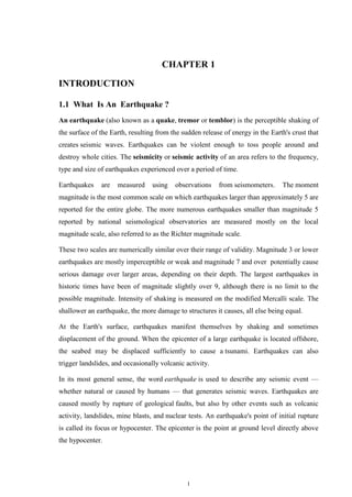
- 1. 1 CHAPTER 1 INTRODUCTION 1.1 What Is An Earthquake ? An earthquake (also known as a quake, tremor or temblor) is the perceptible shaking of the surface of the Earth, resulting from the sudden release of energy in the Earth's crust that creates seismic waves. Earthquakes can be violent enough to toss people around and destroy whole cities. The seismicity or seismic activity of an area refers to the frequency, type and size of earthquakes experienced over a period of time. Earthquakes are measured using observations from seismometers. The moment magnitude is the most common scale on which earthquakes larger than approximately 5 are reported for the entire globe. The more numerous earthquakes smaller than magnitude 5 reported by national seismological observatories are measured mostly on the local magnitude scale, also referred to as the Richter magnitude scale. These two scales are numerically similar over their range of validity. Magnitude 3 or lower earthquakes are mostly imperceptible or weak and magnitude 7 and over potentially cause serious damage over larger areas, depending on their depth. The largest earthquakes in historic times have been of magnitude slightly over 9, although there is no limit to the possible magnitude. Intensity of shaking is measured on the modified Mercalli scale. The shallower an earthquake, the more damage to structures it causes, all else being equal. At the Earth's surface, earthquakes manifest themselves by shaking and sometimes displacement of the ground. When the epicenter of a large earthquake is located offshore, the seabed may be displaced sufficiently to cause a tsunami. Earthquakes can also trigger landslides, and occasionally volcanic activity. In its most general sense, the word earthquake is used to describe any seismic event — whether natural or caused by humans — that generates seismic waves. Earthquakes are caused mostly by rupture of geological faults, but also by other events such as volcanic activity, landslides, mine blasts, and nuclear tests. An earthquake's point of initial rupture is called its focus or hypocenter. The epicenter is the point at ground level directly above the hypocenter.
- 2. 2 1.2 Origin Of Earthquake Earthquakes occur when a build-up of pressure or strain between sections of rocks within the earth's crust is suddenly released, causing minor or severe vibrations on the surface of the land. The point at which layers of rock shift and reposition in relation to one another, is called the focus. This is the effective centre of the earthquake. This energy can be generated by a sudden dislocation of segments of the crust or plate, by a volcanic eruption, or even by manmade explosions. The earth is divided into three main layers - a hard outer crust, a soft middle layer and a centre core. The outer crust is broken into massive, irregular pieces called "plates". The majority of earthquakes in recent years fall under the category of plate tectonics. When two plates interact at their boundaries they put forces on each other. These forces of reaction cause physical and chemical changes at their boundaries. Plates move side to side, up and down, and also interact head on. Earthquakes also occur in these areas where new plates are being created and old plates are being sub ducted into the Earth's interior. Earthquakes which are due to the interaction of plates are called interplate earthquakes. Fig 1.1 Location of focus and epicentre Most natural earthquakes are caused by sudden slippage along a fault zone. The elastic rebound theory suggests that if slippage along a fault is hindered such that elastic strain energy builds up in the deforming rocks on either side of the fault, when the slippage does occur, the energy released causes an earthquake.This theory was discovered by making measurements at a number of points across a fault Prior to an earthquake it was noted that the rocks adjacent to the fault were bending.
- 3. 3 These bends disappeared after an earthquake suggesting that the energy stored in bending the rocks was suddenly released during the earthquake. Friction between the blocks then keeps the fault from moving again until enough strain has accumulated to overcome the friction and generate another earthquake. Once a fault forms, it becomes a zone of weakness - so long as the tectonic stresses continue to be present more earthquakes are likely to occur on the fault. Thus faults move in spurts and this behavior is referred to as Stick Slip. If there is large displacement during an earthquake, a large earthquake will be generated. Smaller displacements generate smaller earthquakes. Note that even for small displacements of only a millimeter per year, after 1 million years, the fault will accumulate 1 km of displacement. Fig 1.2 Different plates around the world 1.2.1 Fault Creep - Some faults or parts of faults move continuously without generating earthquakes. This could occur if there is little friction on the fault & tectonic stresses are large enough to move the blocks in opposite directions. This is called fault creep. If creep is occurring on one part of a fault, it is likely causing strain to build on other parts of the fault.
- 4. 4 1.3 Fault Plane 1.2.2 Seismology, The Study of Earthquakes When an earthquake occurs, the elastic energy is released sending out vibrations that travel throughout the Earth. These vibrations are called seismic waves. The study of how seismic waves behave in the Earth is called seismology. The source of an earthquake is called the focus, which is an exact location within the Earth were seismic waves are generated by sudden release of stored elastic energy. The epicenter is the point on the surface of the Earth directly above the focus. Seismic waves emanating from the focus can travel in several ways, and thus there are several different kinds of seismic waves. Fig 1.4 Focal Motion
- 5. 5 Fig 1.5 Seismometers Modern instruments are digital and don’t require the paper. The record of an earthquake, a seismogram, as recorded by a seismometer, will be a plot of vibrations versus time. On the seismograph, time is marked at regular intervals, so that we can determine the time of arrival of the first P-wave and the time of arrival of the first S-wave. (Note again, that because P-waves have a higher velocity than S-waves, the Pwaves arrive at the seismographic station before the S-waves) allowing people within the system's range to seek shelter before the earthquake's impact is felt.
- 6. 6 CHAPTER 2 LITERATURE REVIEW Vibrations which disturb the earth’s surface caused by waves generated inside the earth are termed as earthquakes. It is said that earthquakes will not kill the life of human but structures which are not constructed in considering the earthquake forces do. At present a major importance has given to earthquake resistant structures in India for human safety. India is a sub-continent which is having more than 60% area in earthquake prone zone. A majority of buildings constructed in India even in seismic zones are designed based on consideration of only gravity load. But earthquake is an occasional load which leads to loss of human life but also disturbs social conditions of India. The earthquake forces in a structure depend on a number of factors such as, • Characteristics of the earthquake (Magnitude, intensity, duration, frequency, etc.) • Distance from the fault. • Site geology. • Type of structure and its lateral load resisting system. Generally, a three phase approach is followed to describe a structure under earthquake loading, i.e. (i) the structure must have adequate lateral stiffness to control the inter-story drifts such that no damage would occur to non-structural elements during minor but frequently occurring earthquakes, (ii) during moderate earthquakes, some damage to non-structural elements is permitted, but the structural element must have adequate strength to remain elastic so that no damage would occur, and (iii) during rare and strong earthquakes, the structure must be ductile enough to prevent collapse by aiming for repairable damage which would ascertain economic feasibility.
- 7. 7 2.1 Case Studies 2.1.1 Comparison Between Structural Analysis of Residential Building ( Flat Scheme) Subjected to Gravity With Respect to Seismic Forces ( In zone II and zone III ) For Different Storey Heights. The recent development in methods to analyze the RC frame structure brings us to this study. This paper is approach to introduce the comparison between structural analysis of Residential building (Flat Scheme) subjected to gravity with respect to seismic forces ( in zone II and zone III) for different storey heights. For structural engineers, seismic load should be considered as important aspect that needs to be included in the building design. However majority of buildings constructed in India are designed for gravity loading only and poorly detailed to accommodate lateral loads. The purpose of this paper is to investigate the comparison between structural analysis of residential building subjected to gravity with respect to seismic forces in zone II and zone III for different storey heights. The analysis for residential building (G+3) is carried out by using software SAP by seismic coefficient method. Columns, beams and footing has been drawn. Microsoft office Excel 2007 programs were used for drafting , and analysis of columns, beams and footing. This analysis gives better understanding the seismic performance of buildings. The results show that the building which is designed only for gravity load is found inadequate to resist seismic load in zone II and zone III. 2.1.2 Seismic Analysis of Structures under Different Soil Conditions In India, multi-storied buildings are usually constructed due to high cost and scarcity of land. In order to utilize maximum land area, builders and architects generally propose asymmetrical plan configurations. These asymmetrical plan buildings, which are constructed in seismic prone areas, are likely to be damaged during earthquake. Earthquake is a natural phenomenon which can generate the most destructive forces on structures. Buildings should be made safe for lives by proper design and detailing of structural members in order to have a ductile form of failure. The concept of earthquake resistant design is that the building should be designed to resist the forces, which arises due to Design Basis Earthquake, with only minor damages and the forces, which arises due to Maximum Considered Earthquake, with some accepted structural damages but no collapse.
- 8. 8 This project report comprises of seismic analysis and design of an five-storied R.C. building with asymmetrical plan in different soil conditions. 2.2 Motivation It is said that earthquakes will not kill the life of human but structures which are not constructed in considering the earthquake forces do. At present a major importance has given to earthquake resistant structures in India for human safety. India is a sub-continent which is having more than 60% area in earthquake prone zone. A majority of buildings constructed in India are designed based on consideration of permanent , semi- permanent , movable loads. But earthquake is an occasional load which leads to loss of human life but also disturbs social conditions of India. Therefore Earthquake analysis of Residential Building is most important for different zones of the country. This study helps to predict the future aspects of the Earthquake of that area by studying the present motion and time of the Earthquake. This study helps to improve the type of construction of the buildings of the Earthquake prone area.
- 9. 9 CHAPTER 3 METHODOLOGY To accomplish the objectives of the project, the following steps have been given below: 1. To prepare Plan & Elevation of G+ 9 Residential Building. 2. To Study the Physical Parameters of the Building. 3. To study the different methods such as Seismic Coefficient Method & Moment Resisting Method . 4. To study the different IS Codes: IS IS-456:200 :DESIGN CODE FOR RCC STRUCTURES IS-875(PART 1) :CODE FOR DEAD LOADS IS-875(PART 2) :CODE FOR IMPOSED LOADS IS-875(PART 3) :CODE FOR WIND LOADS 5. To consider all the Moments and forces acting on the building according to their zone. 6. To analyse and design the structure using STAAD.PRO and checking the result manually. 7. To prepare conclusion of the result obtained.
- 10. 10 3.1 Block Diagram Fig 3.1 Block Diagram
- 11. 11 CHAPTER 4 PLAN AND ELEVATION OF A RESIDENTIAL BUILDING Fig 4.1 Plan & Elevation of Residential Building
- 12. 12 CHAPTER 5 PHYSICAL PARAMETERS OF A BUILDING 5.1 Physical Parameters 1.Utility of building :Residential building 2.No of storeys :G+9 3.Shape of the building :rectangular 4.Type of construction : R.C.C framed structure 5.Type of walls :brick wall 6. Physical Parameters • Length = 4 bays @ 5m =20m • Width = 3 bays@ 5m = 15m • Height = 3m + 9 storey @ 3m = 30m • Grade of Concrete = M35 • Grade of steel used = Fe 415
- 13. 13 5.2 Structural Model 1. Size of Column = 400 mm x 400 mm 2. Size of Beam = 250 mm x 300 mm 3. Thickness of external wall = 0.23 4. Thickness of slab = 150mm ( thick) 5. Live load on floor = 4 kN/ m2 6. Self weight = bD Y = 0.25x0.3x25= 1.875 kN 7. Unit wt of Concrete =25 kN/ m3 8. Unit wt of Mud phuska =20 kN/ m3 9. Height of each storey = 3m 10. Height from ground Floor to First floor = 3m 11. Dead load on roof = 6.75 kN/ m2 12. Dead load on floor = 4.75 kN/ m2
- 14. 14 CHAPTER 6 TYPES OF LOADING ON A STRUCTURE Loading on tall buildings is different from low-rise buildings in many ways such as large accumulation of gravity loads on the floors from top to bottom, increased significance of wind loading and greater importance of dynamic effects. Thus, multi-storeyed structures need correct assessment of loads for safe and economical design. Except dead loads, the assessment of loads can not be done accurately. Live loads can be anticipated approximately from a combination of experience and the previous field observations. Wind and earthquake loads are random in nature and it is difficult to predict them. They are estimated based on a probabilistic approach. Loads cause stresses, deformations, and displacements in structures. Assessment of their effects is carried out by the methods of structural analysis. Excess load or overloading may cause structural failure, and hence such possibility should be either considered in the design or strictly controlled. 6.1 Gravity Loads Dead loads due the weight of every element within the structure as well as live loads that are acting on the structure when in service constitute gravity loads. The dead loads are calculated from the member sizes and estimated material densities. Live loads prescribed by codes are empirical and conservative based on experience and accepted practice. The equivalent minimum loads for office and residential buildings as per IS 875 are as specified in following Table as mentioned below .
- 15. 15 Fig 6.1 Load Magnitude 6.1.1 Dead loads are static forces that are relatively constant for an extended time. They can be in tension or compression. The term can refer to a laboratory test method or to the normal usage of a material or structure. Fig 6.2 Dead Load 6.1.2 Live loads are usually unstable or moving loads. These dynamic loads may involve considerations such as impact, momentum, vibration, slosh dynamics of fluids, etc. Live loads, or imposed loads, are temporary, of short duration, or a moving load. These dynamic loads may involve considerations such as impact, momentum, vibration, slosh dynamics of fluids and material fatigue. Live loads, sometimes also referred to as probabilistic loads, include all the forces that are variable within the object's normal operation cycle not including construction or environmental loads.
- 16. 16 Roof and floor live loads are produced during maintenance by workers, equipment and materials, and during the life of the structure by movable objects, such as planters and people. Bridge live loads are produced by vehicles traveling over the deck of the bridge. Fig 6.3 Live Load 6.1.3 An impact load is one whose time of application on a material is less than one-third of the natural period of vibration of that material. 6.1.4 Cyclic loads on a structure can lead to fatigue damage, cumulative damage, or failure. These loads can be repeated loadings on a structure or can be due to vibration. 6.2 Environmental Loads These are loads that act as a result of weather, topography and other natural phenomena. Wind loads Snow, rain and ice loads Seismic loads Hydrostatic loads Temperature changes Ponding loads Frost heaving Lateral pressure of soil, groundwater or bulk materials Loads from fluids or floods Permafrost melting
- 17. 17 6.2.1 Wind load The wind loading is the most important factor that determines the design of tall buildings over 10 storeys, where storey height approximately lies between 2.7 – 3.0 m. Buildings of up to 10 storeys, designed for gravity loading can accommodate wind loading without any additional steel for lateral system. Usually, buildings taller than 10 storeys would generally require additional steel for lateral system. This is due to the fact that wind loading on a tall building acts over a very large building surface, with greater intensity at greater heights and with a larger moment arm about the base. So, the additional steel required for wind resistance increases non-linearly with height as shown in Fig. 3.7. Fig 6.4 Weight of Steel in multistorey Building As shown in Fig.3.7 the lateral stiffness of the building is a more important consideration than its strength for tall multi-storeyed structures. Wind has become a major load for the designer of multi-storeyed buildings. Prediction of wind loading in precise scientific terms may not be possible, as it is influenced by many factors such as the form of terrain, the shape, slenderness, the solidity ratio of building and the arrangement of adjacent buildings. The appropriate design wind loads are estimated based on two approaches. Static approach is one, which assumes the building to be a fixed rigid body in the wind. This method is suitable for buildings of normal height, slenderness, or susceptible to vibration in the wind. The other approach is the dynamic approach.
- 18. 18 6.2.2 Seismic Loads Seismic motion consists of horizontal and vertical ground motions, with the vertical motion usually having a much smaller magnitude. Further, factor of safety provided against gravity loads usually can accommodate additional forces due to vertical acceleration due to earthquakes. So, the horizontal motion of the ground causes the most significant effect on the structure by shaking the foundation back and forth. The mass of building resists this motion by setting up inertia forces throughout the structure. Then magnitude of the horizontal shear force F depends on the mass of the building M, the acceleration of the ground , and the nature of the structure. If a building and the foundation were rigid, it would have the same acceleration as the ground as given by Newton’s second law of motion, i.e. F = Ma. However, in practice all buildings are flexible to some degree. For a structure that deforms slightly, thereby absorbing some energy, the force will be less than the product of mass and acceleration. But, a very flexible structure will be subject to a much larger force under repetitive ground motion. This shows the magnitude of the lateral force on a building is not only dependent on acceleration of the ground but it will also depend on the type of the structure. As an inertia problem, then dynamic response of the building plays a large part in influencing and in estimating the effective loading on the structure. The earthquake load is estimated by Seismic co-efficient method or Response spectrum method. 6.3 Other Loads Engineers must also be aware of other actions that may affect a structure, such as: Foundation settlement or displacement Fire Corrosion Explosion Creep or shrinkage Impact from vehicles or machinery vibration
- 19. 19 6.4 Load Combinations A load combination results when more than one load type acts on the structure. Building codes usually specify a variety of load combinations together with load factors(weightings) for each load type in order to ensure the safety of the structure under different maximum expected loading scenarios. For example, in designing a staircase, a dead load factor may be 1.2 times the weight of the structure, and a live load factor may be 1.6 times the maximum expected live load. These two "factored loads" are combined (added) to determine the "required strength" of the staircase. The reason for the disparity between factors for dead load and live load, and thus the reason the loads are initially categorized as dead or live is because while it is not unreasonable to expect a large number of people ascending the staircase at once, it is less likely that the structure will experience much change in its permanent load. The various loads should, therefore, be combined in accordance with the stipulations in the relevant design codes. a. DL b. DL+IL c. DL+WL d. DL+EL e. DL+TL f. DL+IL+WL g. DL+IL+EL16 h. DL+IL+TL i. DL+WL+TL j. DL+EL+TL k. DL+IL+WL+TL l. DL+IL+EL+TL (DL = dead load, IL = imposed load, WL = wind load, EL = earthquake load, TL = temperature load)
- 20. 20 CHAPTER 7 CALCULATION OF GRAVITY LOAD ON A STRUCTURE For Slab 0.15 x 25 = 3.75 kN/ m2 Floor Finish = 1 kN/ m2 Dead Load = 4.75 kN/ m2 For Beam 0.25 x 0.3 x25 = 1.875 kN/ m2 For Column 3 x 0.4 x 0.4 x 25 = 12 kN Thickness of External Wall 0.25 x 20 x (3-0.45) x 2.55 = 12.75 kN Load on Top Floor 0.15 X 25 = 3.75 kN/ m2 Mud Phuska = 0.1 x 20 = 2 kN/ m2 Finishing Load = 1 kN/ m2 Total Load on Roof =6.75 kN/ m2 Load on Floors ( 1 to 9) Weight on Slab = 20 x 15 x 4.75 = 1425 kN Weight on Beam = 32 x 5 x 1.88 = 300.8 kN Weight on Column = 20 x 12 = 240 kN Weight on Exterior Wall = 70 x 12.75 = 892.5 kN Live Load = 20 x 15 x 4 = 1200 kN Dead Load = 2858.3 kN Total Weight = 2858.3 + ( 0.5 x 1200) = 3458.3 kN Load on Roof Weight on Slab = 20x 15 x 6.75 = 2025 kN Weight on Beam = 5 x 32 x 1.88 = 300.8 kN Weight on Column = 0.3 x 20 x 12 = 72 kN Parapet Weight = 1x20x0.25x70 =350 kN Total Load on Roof , W’ = 2025 + 300.8 + 72 + 350 = 2747.8 kN
- 21. 21 Load Below Plinth Weight on Beam = 32 x 5 x 1.88 =300.8 kN Weight on Column = 0.3 x 20 x 12 =72 kN Total load , W‖ = 372.8 kN Self Weight ( W) = W’ + 9W +W‖ = 2747.8 + (9 X 3458.3) + 372.8 ∑W = 34245.2 kN
- 22. 22 CHAPTER 8 CALCULATION OF BASE SHEAR 8.1 What Is Base Shear? Base shear is an estimate of the maximum expected lateral force that will occur due to seismic ground motion at the base of a structure. Calculations of base shear (V) depend on: soil conditions at the site proximity to potential sources of seismic activity (such as geological faults) probability of significant seismic ground motion the level of ductility and overstrength associated with various structural configurations and the total weight of the structure the fundamental (natural) period of vibration of the structure when subjected to dynamic loading 8.2 Codal Provisions For Calculating Base Shear 8.2.1 Design Seismic Base Shear The total design lateral force or design seismic base shear ( VB)along any principal direction shall be determined by the following expression: Vb = Ah x W Where Ah = Design horizontal acceleration spectrum value as per Clause 6.4.2 (IS 1893), using the fundamental natural period T, as per Clause 7.6 (IS 1893) in the considered direction of vibration, and W = Seismic weight of the building as per Clause 7.4.2 ( IS 1893) 8.2.2 Fundamental Natural Period The approximate fundamental natural period of vibration ( T, ), in seconds, of a moment-resisting frame building without brick in.fd panels may be estimated by the empirical expression: T. = 0,075 h07s for RC frame building , T = 0.085 h075 for steel frame building
- 23. 23 where h = Height of building, in m. This excludes the basement storeys, where basement walls are connected with the ground floor deck or fitted between the building columns. But it includes the basement storeys, when they are not so connected. The approximate fundamental natural period of vibration ( T, ), in seconds, of all other buildings, including moment-resisting frame buildings with brick infill panels, may be estimated by the empirical expression: Ta = 0.09 / √1d where h= Height ofbuilding, in m as defined in Clause 7.6.l of IS 1893 and d= Base dimension of the building at the plinth level, in m, along the considered direction of the lateral force. 8.2.3 Distribution of Design Force Vertical Distribution of Base Shear to Differmt Floor LeveLs The design base shear ( V) computed in section 7.5.3 of IS 1893 – 2000 shall be distributed along the height of the building as per the following expression:
- 24. 24 8.2.4 Distribution of Horizontal Design Lateral Force to Different Lateral Force Resisting Elements In case of buildings whose floors are capable of providing rigid horizontal diaphragm action, the total shear in any horizontal plane shall be distributed to the various vertieal elements of lateral force resisting system, assuming the floors to be infinitely rigid in the horizontal plane. In case of building whose floor diaphragms can not be treated as infinitely rigid in their own plane, the lateral shear at each floor shall be distributed to the vertical elements resisting the lateral forces, considering the in-plane flexibility of the diaphragms. 8.3 Base Shear Calculation For Zone 4 Z= 0.24 , I= 1 ( Residential Building) , R=5 ( SMRF) Seismic Weight Floor area = 15 x 20 = 300 sqm Live Load = 4kN/m2 Fundamental Period EL in X direction , T = 0.09h/√d [IS 1893 (Part 1):2002, Clause 7.6.1] h = 30+1.5 = 31.5 m Therefore , T = 0.09 X 31.5 / (√20) = 0.633 sec Since building is located on Type II ( Medium soil) For T= 0.633 sec , Sa/g = 1.36/ 0.664 = 2.12 Therefore , Z =0.24 Ah = ZI(Sa/G)/2R [IS 1893 (Part 1):2002, Clause 6.4.2] Ah = (0.24 x 2.12 x 1 ) / ( 2x 5) = 0.051 Design Base Shear VB= Ahx ∑ W = 0.051 x 34245.2 = 1746.5 kN EL in Y – direction , T = 0.09h/√d [IS 1893 (Part 1):2002, Clause 7.6.1] = 0.09 x 31.5 / √15 = 0.73 sec Sa/g = 1.36/ 0.73 = 1.86 , Ah = (0.24 x1.86 x1) / (2x5x1) = 0.045 Design Base Shear , Vh ( In Y – Direction ) = 0.045 x 34245.2 = 1541.03 kN
- 25. 25 8.4 Base Shear Calculation For Zone 5 EL in X – direction Z= 0.36 , Ah = ZI(Sa/G)/2R [IS 1893 (Part 1):2002, Clause 6.4.2] = 0.36 x2.12x1.0 /10 = 0.07632 Base shear VB= Ahx ∑ W =0.07632 x 34245.2= 2619.75 kN EL in Y – direction T= 0.09h / √d = 0.09x 33x √20 = 0.73 sec Ah = (0.36 x1.86 x1) / (2x5x1) = 0.067 Design Base shear , VB= Ahx ∑ W = 0.067 x 34245.2 = 2071.17 kN
- 26. 26 CHAPTER 9 DISTRIBUTION OF BASE SHEAR 9.1 For Zone 4 Table No. 9.1 Base Shear for Zone 4 Fig 9.1 Distribution of Base Shear along X- Direction for Zone -4
- 27. 27 Fig 9.2 Distribution of Base Shear along Y- Direction for Zone -4 9.2 For Zone 5 Table no 9.2 Base Shear for Zone 5
- 28. 28 Fig 9.3 Distribution of Base Shear along X- Direction for Zone -5 Fig 9.4 Distribution of Base Shear along Y- Direction for Zone -5
- 29. 29 CHAPTER 10 ABOUT SOFTWARES This project is mostly based on software and it is essential to know the details about these software’s. List of software’s used 1. Staad pro(v8i) 2. Auto cad Staad pro Staad Foundation Auto Cad Fig 10.1 Softwares 10.1 Staad Staad is powerful design software licensed by Bentley .Staad stands for structural analysis and design . Any object which is stable under a given loading can be considered as structure. So first find the outline of the structure, where as analysis is the estimation of what are the type of loads that acts on the beam and calculation of shear force and bending moment comes under analysis stage. Design phase is designing the type of materials and its dimensions to resist the load. this we do after the analysis. To calculate shear force and bending moment diagram of a complex loading beam it takes about an hour. So when it comes into the building with several members it will take a week. Staad pro is a very powerful tool which does this job in just an hour’s staad is a best alternative for high rise buildings. Now a days most of the high rise buildings are designed by staad which makes a compulsion for a civil engineer to know about this software. 10.1.1 Alternatives for staad: struts, robot, sap, which gives details clearly regarding reinforcement and calculations.
- 30. 30 10.2 Staad Foundation : Staad foundation is a powerful tool used to calculate different types of foundations. It is also licensed by Bentley software’s. All Bentley software’s cost about 10 lakhs and so all engineers can’t use it due to heavy cost. Analysis and design carried in Staad and post processing in staad gives the load at various supports. These supports are to be imported into these software to calculate the footing details i.e., regarding the geometry and reinforcement details. This software can deal different types of foundations SHALLOW (D<B) 1. Isolated (Spread) Footing 2.Combined (Strip) Footing 3.Mat (Raft) Foundation DEEP (D>B) 1.Pile Cap 2. Driller Pier 1. Isolated footing is spread footing which is common type of footing. 2. Combined Footing or Strap footing is generally laid when two columns are very near to each other. 3. Mat foundation is generally laid at places where soil has less soil bearing capacity. 4. pile foundation is laid at places with very loose soils and where deep excavations are required. So depending on the soil at type we has to decide the type of foundation required. Also lot of input data is required regarding safety factors, soil, materials used should be given in respective units. 10.3 Auto Cad: AutoCAD is powerful software licensed by auto desk. The word auto came from auto desk company and cad stands for computer aided design. AutoCAD is used for drawing different layouts, details, plans, elevations, sections and different sections can be shown in auto cad. It is very useful software for civil, mechanical and also electrical engineer. The importance of this software makes every engineer a compulsion to learn this software’s. We used AutoCAD for drawing the plan, elevation of a residential building. We also used AutoCAD to show the reinforcement details and design details of a stair case. AutoCAD is a very easy software to learn and much user friendly for anyone to handle and canbe learn quickly.
- 31. 31 CHAPTER 11 WORKING WITH STAAD.PRO 11.1 Input Generation : The GUI (or user) communicates with the STAAD analysis engine through the STD input file. That input file is a text file consisting of a series of commands which are executed sequentially. The commands contain either instructions or data pertaining to analysis and/or design. The STAAD input file can be created through a text editor or the GUI Modeling facility. In general, any text editor may be utilized to edit/create the STD input file. The GUI Modeling facility creates the input file through an interactive menu-driven graphics oriented procedure. Fig 11.1: STAAD input file 11.2 Types Of Structures : A STRUCTURE can be defined as an assemblage of elements. STAAD is capable of analyzing and designing structures consisting of frame, plate/shell and solid elements. Almost any type of structure can be analyzed by STAAD. A SPACE structure, which is a three dimensional framed structure with loads applied in any plane, is the most general.
- 32. 32 A PLANE structure is bound by a global X-Y coordinate system with loads in the same plane. A TRUSS structure consists of truss members which can have only axial member forces and no bending in the members. A FLOOR structure is a two or three dimensional structure having no horizontal (global X or Z) movement of the structure [FX, FZ & MY are restrained at every joint]. The floor framing (in global X-Z plane) of a building is an ideal example of a FLOOR structure. Columns can also be modeled with the floor in a FLOOR structure as long as the structure has no horizontal loading. If there is any horizontal load, it must be analyzed as a SPACE structure. 11.3 Generation Of The Structure: The structure may be generated from the input file or mentioning the co-ordinates in the GUI. The figure below shows the GUI generation method. Fig 11.2: generation of structure through GUI 11.4 Supports: Supports are specified as PINNED, FIXED, or FIXED with different releases (known as FIXED BUT). A pinned support has restraints against all translational movement and none against rotational movement. In other words, a pinned support will have reactions for all forces but will resist no moments. A fixed support has restraints against all directions of movement. Translational and rotational springs can also be specified. The springs are represented in terms of their spring constants.
- 33. 33 A translational spring constant is defined as the force to displace a support joint one length unit in the specified global direction. Similarly, a rotational spring constant is defined as the force to rotate the support joint one degree around the specified global direction. 11.5 Loads : Loads in a structure can be specified as joint load, member load, temperature load and fixed-end member load. STAAD can also generate the self-weight of the structure and use it as uniformly distributed member loads in analysis. Any fraction of this self weight can also be applied in any desired direction. 11.5.1 Joint loads: Joint loads, both forces and moments, may be applied to any free joint of a structure. These loads act in the global coordinate system of the structure. Positive forces act in the positive coordinate directions. Any number of loads may be applied on a single joint, in which case the loads will be additive on that joint. 11.5.2 Member load: Three types of member loads may be applied directly to a member of a structure. These loads are uniformly distributed loads, concentrated loads, and linearly varying loads (including trapezoidal). Uniform loads act on the full or partial length of a member. Concentrated loads act at any intermediate, specified point. Linearly varying loads act over the full length of a member.
- 34. 34 Fig 11. 3 Member Load configuration 11.5.3 Area/floor load: Many times a floor (bound by X-Z plane) is subjected to a uniformly distributed load. It could require a lot of work to calculate the member load for individual members in that floor. However, with the AREA or FLOOR LOAD command, the user can specify the area loads (unit load per unit square area) for members. The program will calculate the tributary area for these members and provide the proper member loads. The Area Load is used for one way distributions and the Floor Load is used for two way distributions. 11.5.4 Fixed end member load: Load effects on a member may also be specified in terms of its fixed end loads. These loads are given in terms of the member coordinate system and the directions are opposite to the actual load on the member. Each end of a member can have six forces: axial; shear y; shear z; torsion; moment y, and moment z. 11.5.5 Load Generator Load generation is the process of taking a load causing unit such as wind pressure, ground movement or a truck on a bridge, and converting it to a form such as member load or a joint load which can be then be used in the analysis. 11.5.6 Moving Load Generator: This feature enables the user to generate moving loads on members of a structure. Moving load system(s) consisting of concentrated loads at fixed specified distances in both directions on a plane
- 35. 35 can be defined by the user. A user specified number of primary load cases will be subsequently generated by the program and taken into consideration in analysis. 11.5.7 Seismic Load Generator: The STAAD seismic load generator follows the procedure of equivalent lateral load analysis. It is assumed that the lateral loads will be exerted in X and Z directions and Y will be the direction of the gravity loads. Thus, for a building model, Y axis will be perpendicular to the floors and point upward (all Y joint coordinates positive). For load generation per the codes, the user is required to provide seismic zone coefficients, importance factors, and soil characteristic parameters. Instead of using the approximate code based formulas to estimate the building period in a certain direction, the program calculates the period using Raleigh quotient technique. This period is then utilized to calculate seismic coefficient C. After the base shear is calculated from the appropriate equation, it is distributed among the various levels and roof per the specifications. The distributed base shears are subsequently applied as lateral loads on the structure. These loads may then be utilized as normal load cases for analysis and design.11.5.8 Wind Load Generator: The STAAD Wind Load generator is capable of calculating wind loads on joints of a structure from user specified wind intensities and exposure factors. Different wind intensities may be specified for different height zones of the structure. Openings in the structure may be modeled using exposure factors. An exposure factor is associated with each joint of the structure and is defined as the fraction of the influence area on which the wind load acts. Built-in algorithms automatically calculate the exposed area based on the areas bounded by members (plates and solids are not considered), then calculates the wind loads from the intensity and exposure input and distributes the loads as lateral joint loads. 11.6 Section Types For Concrete Design: The following types of cross sections for concrete members can be designed. For Beams Prismatic (Rectangular & Square) & T-shape For Columns Prismatic (Rectangular, Square and Circular) 11.7 Design Parameters : The program contains a number of parameters that are needed to perform design as per IS 13920. It accepts all parameters that are needed to perform design as per IS: 456. Over and above it has some other parameters that are required only when designed is performed as per IS: 13920. Default
- 36. 36 parameter values have been selected such that they are frequently used numbers for conventional design requirements. These values may be changed to suit the particular design being performed by this manual contains a complete list of the available parameters and their default values. It is necessary to declare length and force units as Millimeter and Newton before performing the concrete design. 11.8 Beam Design : Beams are designed for flexure, shear and torsion. If required the effect of the axial force may be taken into consideration. For all these forces, all active beam loadings are prescanned to identify the critical load cases at different sections of the beams. For design to be performed as per IS: 13920 the width of the member shall not be less than 200mm. Also the member shall preferably have a width-to depth ratio of more than 0.3.
- 37. 37 CHAPTER 12 ANALYSIS OF G +9 RCC FRAMED BUILDING USING STAAD.Pro Fig 12.1: plan of the G+9 residential building All columns = 0.40 * 0.40 m All beams = 0.25 * 0.3 m All slabs = 0.15 m thick
- 38. 38 Fig 12..2: elevation of the G+9 storey building 12.1 Physical Parameters Of Building: Length = 4 bays @ 5.0m = 20.0m Width = 3 bays @ 5 m =15.0m Height = 3 m + 9 storeys @ 3m = 30 m Live load on the floors is 4kN/m2 Live load on the roof is 1.2 kN/m2 Grade of concrete and steel used: Used M35 concrete and Fe 415 steel
- 39. 39 12.2 Generation Of Member Property: Fig 12.3: Generation of member property Generation of member property can be done in STAAD.Pro by using the window as shown above. The member section is selected and the dimensions have been specified. The beams are having a dimension of 0.25 * 0.3 m and the columns are having a dimension of 0.4 * 0.4 m . 12.3 Supports : The base supports of the structure were assigned as fixed. The supports were generated using the STAAD.Pro support generator.
- 40. 40 Fig 12.4: Fixing supports of the structure 12.4 Materials For The Structure: The materials for the structure were specified as concrete with their various constants as per standard IS code of practice. The loadings were calculated partially manually and rest was generated using STAAD.Pro load generator. The loading cases were categorized as: 1. Self-weight 2. Dead load from slab 3. Live load 4. Seismic load 5. Load combinations Fig 12.5 Creating New Load Definition
- 41. 41 12.5 Self-Weight The self weight of the structure can be generated by STAAD.Pro itself with the self weight command in the load case column. 12.6 Dead Load From Slab: Dead load from slab can also be generated by STAAD.Pro by specifying the floor thickness and the load on the floor per sq m. Calculation of the load per sq m was done considering theweight of beam, weight of column, weight of RCC slab, and over roof. Fig 12.6: Input window of floor load generator
- 42. 42 Fig 12.7: load distribution by trapezoidal method Fig 12.8: The structure under DL from slab 12.7 Live Load: The live load considered in each floor was 2.5 KN/sq m and for the terrace level it was considered to be 0.75 KN/sq m. The live loads were generated in a similar manner as done in the earlier case for dead load in each floor. This may be done from the member load button from the load case column.
- 43. 43 Fig 12.9: The structure under live load 12.8 Seismic Load: The seismic load values were calculated as per IS 1893-2002. STAAD.Pro has a seismic load generator in accordance with the IS code mentioned. Description: The seismic load generator can be used to generate lateral loads in the X and Z directions only. Y is the direction of gravity loads. This facility has not been developed for cases where the Z axis is set to be the vertical direction using the ―SET Z UP‖ command. 12.9 Methodology: The design base shear is computed by STAAD in accordance with the IS: 1893(Part 1)-2002. V = Ah*W Where, Ah = (Z*I*Sa)/ (2*R*g) STAAD utilizes the following procedure to generate the lateral seismic loads. User provides seismic zone co-efficient and desired "1893(Part 1)-2002 specs" through the DEFINE 1893 LOAD command. Program calculates the structure period (T). Program calculates Sa/g utilizing T. Program calculates V from the above equation. W is obtained from the weight data provided by the user through the DEFINE 1893 LOAD command.
- 44. 44 The total lateral seismic load (base shear) is then distributed by the program among different levels of the structure per the IS: 1893(Part 1)-2002 procedures. Fig 12.10: seismic load definition Fig 12.11: structure under seismic load 12.10 Load Combination: The structure has been analyzed for load combinations considering all the previous loads in proper ratio. In the first case a combination of self-weight, dead load, live load and wind load was taken in to consideration. In the second combination case instead of wind load seismic load was taken into consideration.
- 45. 45 Fig 12.12 Load combination with seismic load Fig 12.13: GUI showing the analyzing window
- 46. 46 CHAPTER 13 BEAM DESIGN Beams transfer load from slabs to columns .beams are designed for bending. In general we have two types of beam: single and double. Similar to columns geometry and perimeters of the beams are assigned. Design beam command is assigned and analysis is carried out, now reinforcement details are taken. 13.1 Beam : a reinforced concrete beam should be able to resist tensile, compressive and shear stress induced in it by loads on the beam. There are three types of reinforeced concrete beams 1.) single reinforced beams 2.) double reinforced concrete 3.) flanged beams 13.1.1 Singly reinforced beams: In singly reinforced simply supported beams steel bars are placed near the bottom of the beam where they are more effective in resisting in the tensile bending stress. I cantilever beams reinforcing bars placed near the top of the beam, for the same reason as in the case of simply supported beam. 13.1.2 Doubly reinforced concrete beams: It is reinforced under compression tension regions. The necessity of steel of compression region arises due to two reasons. When depth of beam is restricted. The strength availability singly reinforced beam is in adequate. At a support of continuous beam where bending moment changes sign such as situation may also arise in design of a beam circular in plan.
- 47. 47 Figure shows the bottom and top reinforcement details at three different sections. These calculations are interpreted manually Fig 13.1 A diagram of the reinforcement details of beam 13.2 Deflection : Fig 13.2 A diagram of the deflection of a beam in global X- Direction.
- 48. 48 13.3 Output Of Sample Beam Fig 13.3 Staad. Pro Output 13.4 Shear Diagram Fig 13.4 A diagram of the shear force of a beam.
- 49. 49 13.5 Check For The Design Of Beam (no. 481): Given data: Cross section of beam : b x d = 300mm x400 mm Vertical shear force = vu =145.93 kN τc = 0.29 N/mm2 (from table 19 of IS 456 200) Minimum Shear Reinforcement: When τv is less than τc , given in Table 19, minimum shear reinforcement shall -be provided Design of Shear Reinforcement: When τv exceeds τc, given in Table 19, shear reinforcement shall be provided in any of the following forms: a) Vertical stirrups, b) Bent-up bars along with stirrups, and c) Inclined stirrups, τv = vu/(b x d) (As per clause 40.1 of IS 456-2000) =145.93 x 10³/(400x300) =1.216 N/mm2 τv ≥ τc design reinforcement Vus = Vu- τcxbxd (As per clause 40.4 of IS 456-2000) = 145.93 x10³ -0.29x400x300 = 111100 N Shear reinforcement shall be provided to carry a shear equal to Vu - τc bd The strength of shear reinforcement Vus, shall be calculated as below: For vertical stirrups: Vus = 0.87 fyAsvd/Sv (As per clause 40.4 of IS 456-2000) Asv = total cross-sectional area of stirrup legs or bent-up bars within a distance Sv. Sv = spacing of the stirrups or bent-up bars along the length of the member, τv = nominal shear stress τc = design shear strength of the concrete, b = breadth of the member which for flanged beams, shall be taken as the breadth of the web bw, fy = characteristic strength of the stirrup or bent-up reinforcement which shall notbe taken greater than 415 N/mm2,
- 50. 50 α = angle between the inclined stirrup or bent- up bar and the axis of the member, not less than 45‖, and d = effective depth. 111130 N= 0.87x415x2xπx82x400/Sv Sv = 140 mm Sv should not be more than the following 1. 0.75xd = 0.75 x 400 = 300 mm 2. 300 mm 3. Minimum shear reinforcement spacing = Sv min Minimum shear reinforcement: Minimum shear reinforcement in the form of stirrups shall be provided such that: Asv/bSv ≥ 0.4/ 0.87fy (As per clause 26.5.1.6 of IS 456-2000) Asv = total cross-sectional area of stirrup legs effective in shear, Sv = stirrup spacing along the length of the member, b = breadth of the beam or breadth of the web of flanged beam, and fy = characteristic strength of the stirrup reinforcement in N/mm* which shall not be taken greater than 415 N/mn2 Sv=2x(π/4)x82x0.87x415/(0.4x300) =302 mm. Provided 2 legged 8mm @150 mm strirrups . Hence matched with staad output.
- 51. 51 CHAPTER 14 COLUMN DESIGN A column or strut is a compression member, which is used primary to support axial compressive loads and with a height of at least three it is least lateral dimension. A reinforced concrete column is said to be subjected to axially loaded when line of the resultant thrust of loads supported by column is coincident with the line of C.G 0f the column I the longitudinal direction. Depending upon the architectural requirements and loads to be supported,R.C columns may be cast in various shapes i.e square ,rectangle, and hexagonal ,octagonal,circular.Columns of L shaped or T shaped are also sometimes used in multistoried buildings. The longitudinal bars in columns help to bear the load in the combination with the concrete.The longitudinal bars are held in position by transverse reinforcement, or lateral binders. The binders prevent displacement of longitudinal bars during concreting operation and also check the tendency of their buckling towards under loads. 14.1 Positioning Of Columns: Some of the guiding principles which help the positioning of the columns are as follows:- A) Columns should be preferably located at or near the corners of the building and at the intersection of the wall, but for the columns on the property line as the following requirements some area beyond the column, the column can be shifted inside along a cross wall to provide the required area for the footing with in the property line. alternatively a combined or a strap footing may be provided. B) The spacing between the column is governed by the lamination on spans of supported beams, as the spanning of the column decides the the span of the beam. As the span of the of the beam increases, the depth of the beam, and hence the self weight of the beam and the total.
- 52. 52 14.2 Effective Length: The effective length of the column is defined as the length between the points of contraflexure of the buckled column. The code has given certain values of the effective length for normal usage assuming idealized and conditions shown in appendix D of IS - 456(table 24) A column may be classified based as follows based on the type of loading: 1) Axially loaded column 2) A column subjected to axial load and uneasily bending 3) A column subjected to axial load and biaxial bending. 14.3 Axially Loaded Columns: All compression members are to be designed for a minimum eccentricity of load into principal directions. In practice, a truly axially loaded column is rare ,if not nonexistent. Therefore, every column should be designed for a minimum eccentricity .clause 22.4 of IS code E min = (L/500)+(D/300) ,subjected to a minimum of 200 mm. Where L is the unsupported length of the column (see 24.1.3 of the code for definition unsupported length) and D is the lateral dimension of the column in the direction under the consideration. 14.3.1 Axial load and uniaxial bending: A member subjected to axial force and bending shall be designed on the basis of 1) The maximum compressive strength in concrete in axial compression is taken as 0.002 2) The maximum compressive strength at the highly compressed extreme fiber in concrete subjected to highly compression and when there is no tension on the section shall be 0.0035-0.75 times the strain at least compressed extreme fiber. Design charts for combined axial compression and bending are in the form of intersection diagram in which curves for Pu/fck bD verses Mu/fck bD2 are plotted for different values of p/fck where p is reinforcement percentage. 14.3.2 Axial load and biaxial bending: The resistance of a member subjected to axial force and biaxial bending shall be obtained on the basis of assumptions given with neutral axis so chosen as to satisfy the equilibrium of load and moment about two weeks.
- 53. 53 14.4 Design A column may be classify based on deferent criteria such as 1.) shape of the section 2.) slenderness ratio(A=L+D) 3.) type of loading, land 4.) pattern of lateral reinforcement. The ratio of effective column length to least lateral dimension is released to as slenderness ratio. The column design is done by selecting the column and from geometry page assigns the dimensions of the columns. Now analyze the column for loads to see the reactions and total loads on the column by seeing the loads design column by giving appropriate parameters like 1. Minimum reinforcement, max, bar sizes, maximum and minimum spicing. 2. Select the appropriate design code and input design column command to all the column. 3. Now run analysis and select any column to collect the reinforcement details The following figure shows the reinforcement details of a beam in staad. The figure represents details regarding 1. Transverse reinforcement 2. Longitudinal reinforcement The type of bars to be used, amount of steel and loading on the column is represented in the below figure. Fig14.1 Reinforcement details of a column
- 54. 54 14.5 Output For Column 41: Fig 14.2 Staad .Pro Output for Column The following figure shows the deflection of same column. Fig 14.3 Column Deflection along Global X- Direction
- 55. 55 14.6 Check For Column Design : Short axially Loaded columns: Given data fck =30 N/mm2 fy =415N/mm2 puz=2734 N b=350 d=450 Design of reinforcement Area: (As per clause 39.6 of IS 456 2000) Puz=0.45fckAc+0.75fyAsc 2734=0.45*30*(350*450-Asc)+0.75*415*Asc On solving the above equation we get Asc=2041.15 Sq.mm.((Matched with Output) Design of Main(Longitudinal) reinforcement: (As per clause 26.5.3.1 of IS 456-2000 ) 1. The cross sectional area of longitudinal reinforcement shall not be less 0.8% , not more than 6% of the gross cross sectional area of the column. 2. The bars shall not be less than 12 mm in diameter. 3. Spacing of longitudinal bars measured along the periphery of the column shall not exceed 300 mm. Provided main reinforcement : 20 - 12 dia (1.44%, 2261.95 Sq.mm.) Check for Transverse reinforcement : (As per clause 26.5.3.2 of IS 456-2000 ) A) pitch : shall not be more than the least of the following 1) Least lateral dimension of the compression member (350mm). 2) 16 x diameter of longitudinal reinforcement bar = 16x 12 = 192 mm 3) 300 mm B) Diameter : 1) Shall not be less than one fourth of the diameter of main reinforcement. 2) Not less than 6 mm. PROVIDED TIE REINFORCEMENT : Provide 8 mm dia. rectangular ties @ 190 mm c/c
- 56. 56 CHAPTER 15 SLAB DESIGN 15.1 Introduction : Slab is plate elements forming floor and roofs of buildings carrying distributed loads primarily by flexure. One way slab: One way slab are those in which the length is more than twice the breadth it can be simply supported beam or continuous beam. Two way slab: When slabs are supported to four sides two ways spanning action occurs.Such as slab are simply supported on any or continuous or all sides the deflections and bending moments are considerably reduces as compared to those in one way slab. Checks: There is no need to check serviceability conditions, because design satisfying the span for depth ratio. a.) Simply supported slab b.) Continuous beam Fig 15.1 Deflection in One-Way Slab
- 57. 57 Fig 15.2 Diagrams of slab deflection in two way slabs Following figures shows the load distributions in two slabs. Fig 15.3 A Diagram of load distribution of one way and two way slabs
- 58. 58 15.2 Design : 15.2.1 Trial Depth span/d = 1.2 x 26 d = 600.96 = 600 mm A ssume clear cover = 20 mm , diameter =10 mm Effective cover = 25 mm Overall depth = 6000+ 20 mm + 10/2 =625 mm dx = 625 – 25 mm = 600 mm , dy = 625 -10 = 615 mm Acc to condition , Lx = 5000+ 600 =5600 mm , Ly = 5000+615 = 5615 mm Ly / Lx = 1.00 < 2 , Hence Two – way slab has to be design 15.2.2 Load Calculation Live Load = 4 kN/ m2 Self Weight = 4.75 kN/ m2 Floor Finish = 1 kN/ m2 Factored Load = 14.62 kN/ m2 15.2. 3 Design Moments As slab corners are torsionally unrestrained Rankine – Grashoff method may be applied Short Span , Mux = αxWu Lx 2 Long Span , Mux = αyWu Lx 2 αx = 0.0625 , αy = 0.0625 , Mux = 28.655 Kn m , Muy = 28.655 15.2. 4 Design of Reinforcement Rx = Mux / bdx 2 = 0.0795 MPa Rx = Muy / bdy 2 = 0.0757 MPa (Pt)x req / 100 = 132.79 mm2 Provide 10 dia bars required spacing = 591.15 mm Check (i) 3d (ii) 300 mm provide 10 mm dia bars @ 300mm c/c Ast provided = 1000 X 78.5 / 300 = 261.66 mm2 Similarly , (Pt)y req /100 = 129.57 mm2
- 59. 59 Spacing = 100 x 78.5 / 129.57 = 605.85 mm 3d = 1800 mm Ast provided 300 mm Along long span Provide 10 – mm dia bar @ 300 mm c/c = 1000 x 78.5 / 300 = 261.66 mm2 Check for deflection control Pt , x = 132.79 x100 / 103 x 600 = 0.022 % fs = 474 Mpa Kt =1.5 , ( L/ d) max = 20 x 1.5 = 30 , , ( L/ d) provided = 9.33 < 30 OK Check for Shear d = ( 600 + 615 ) / 2 = 607.5 mm = 608 mm Vu = Wu ( 0.5 Lxn – d ) = 14.62 (0.5 x 5 – 0.608 ) = 27.66 KN/m v = 0.0461 Mpa Pt = 0.22 , c = 0.36 Mpa Since , 0.54 > 0.0461 , Hence ok Safe in shear
- 60. 60 CHAPTER 16 FOOTINGS Foundations are structural elements that transfer loads from the building or individual column to the earth .If these loads are to be properly transmitted, foundations must be designed to prevent excessive settlement or rotation, to minimize differential settlement and to provide adequate safety against sliding and overturning. General: 1.) Footing shall be designed to sustain the applied loads, moments and forces and the induced reactions and to assure that any settlements which may occur will be as nearly uniform as possible and the safe bearing capacity of soil is not exceeded. 2.) Thickness at the edge of the footing: in reinforced and plain concrete footing at the edge shall be not less than 150 mm for footing on the soil nor less than 300mm above the tops of the pile for footing on piles. Bearing Capacity Of Soil: The size foundation depends on permissible bearing capacity of soil. The total load per unit area under the footing must be less than the permissible bearing capacity of soil to the excessive settlements. 16.1 Foundation Design: Foundations are structure elements that transfer loads from building or individual column to earth this loads are to be properly transmitted foundations must be designed to prevent excessive settlement are rotation to minimize differential settlements and to provide adequate safety isolated footings for multi storey buildings. These may be square rectangle are circular in plan that the choice of type of foundation to be used in a given situation depends on a number of factors. 1.) Bearing capacity of soil 2.) Type of structure 3.) Type of loads 4.) Permissible differential settlements 5.) economy A footing is the bottom most part of the structure and last member to transfer the load. In order to design footings we used staad foundation software. These are the types of foundations the software can deal. Shallow (D<B)
- 61. 61 1. Isolated (Spread) Footing 2.Combined (Strip) Footing 3.Mat (Raft) Foundation Deep (D>B) 1.Pile Cap 2. Driller Pier The advantage of this software is even after the analysis of staad we can update the following properities if required. The following Parameters can be updated: Column Position Column Shape Column Size Load Cases Support List After the analysis of structure at first we has to import the reactions of the columns from staad pro using import button. After we import the loads the placement of columns is indicated in the figure. Fig 16.1 Placement of columns
- 62. 62 After importing the reactions in the staad foundation the following input data is required regarding materials, Soil type, Type of foundation, safety factors. Type of foundation: ISOLATED. Unit weight of concrete :25 kn/m3 Minimum bar spacing: 50 mm Maximum bar spacing: 500 mm Strength of concrete: 30 N/mm2 Yield strength of steel: 415 N/mm2 Minimum bar size: 6 mm Maximum bar size:40 mm Bottom clear cover:50 mm Unit weight of soil:22 kn/m3 Soil bearing capacity:300 kn/m3 Minimumlength:1000 mm Minimum width:1000 mm Minimum thichness:500 mm Maximum length:12000 mm Maximum width:12000 mm Maximum thickness:1500 mm Plan dimension:50 mm Aspect ratio:1 Safety against friction,overturning,sliding:0.5,1.5,1.5 After this input various properties of the structure and click on design. After the analysis detailed calculation of each and every footing is given with plan and elevation of footing including the manual calculation.
- 63. 63 Isolated Footing 1 Fig 16.2 Plan & Elevation of Footing 16.2 LAYOUT OF FOUNDATION 16.3 The figure shows layout of foundations for each and every column
- 64. 64 Reinforcement details of column is shown below Fig 16.4 Elevation of reinforcements Fig 16.5 Plan of reinforcement
- 65. 65 CHAPTER 17 DUCTILE DETAILING 18.1 Introduction The requirments for designing and detailing of monolethic reinforced concrete building so as to give them sufficient toughtness and ductility to resist severe earthquake shocks without collapse. 18.2 Flexural ( Bending) Members IS 456-2000 the beam and slabs of any structure are flexural member which are designed to resist flexural. The member a width to depth ratio of morn than 3.0. width of member not be less than 200mm. The depth D of the member shall be not more than 1/4th of clear span. 18.3 Longitudinal Reinforcement These bars are provided in the beam to resist bending cracks. The top and bottom reinforcement shall consist of at least two bars throughout the member length. Fig 17.1 Longitudinal Reinforcement 17.4 Web Reinforcement (Transverse Reinforcement Stirrup) The main function of such reinforcement is to prevent concrete from bulging outwords and also prevent longitudional bars from buckling.
- 66. 66 CHAPTER 18 RESULT AND DISCUSSION 18.1 Result When we account for ductile detailing we restrict the force at small value by constructing a special moment resisting frame. In ordinary resisting frame reduction factor is 3 which are designed as per IS 456 so the seismic load value is 1000 kN. While in SMRF reduction factor is 5 acquire by considering ductile detailing it counteract the seismic value to 600 kN. 18.1.1 Bending Moment MX in Beam in Zone 4 & 5 18.1.2 Axial Force FY in Column in Zone 4 & 5 GL EL 0 10 20 30 40 50 60 70 80 zone 4 zone 5 GL EL 0 20 40 GL EL ZONE 4 ZONE 5
- 67. 67 18.1.3 Bending Moment MY in Column in Zone 4 & 5 18.1.4 Axial Force in Beam in Zone 4 & 5 18.1.5 Torsion in Beam in Zone 4 & 5 0 5 10 15 20 25 30 35 40 GL EL ZONE 4 ZONE 5 0 100 200 300 400 500 600 700 800 900 2085.78 sq.mm 1101.78 sq.mm top reinf bottom re 1250 mm 2500 mm 0 200 400 600 800 1000 2085.78 sq.mm 1101.78 sq.mm top reinf bottom re 1250 mm 2500 mm
- 68. 68 18.1.6 Displacement in Column Joint in Zone 4 & 5 18.1.7 Ast Required for Column 18.1.8 Ast comparison at Supports for Zone 4 & Zone 5 0 2 4 6 8 10 12 14 ZONE 4 ZONE 5 GL EL 0.00% 0.50% 1.00% 1.50% 2.00% 2.50% 3.00% 3.50% 4.00% Zone 4 Zone 5 GL EL 0 2000 4000 Z5 Z4 Z5 Z4 gl el support support
- 69. 69 18.2 Discussion 1. In beam the bending moment due to Earthquake load is more as compared to gravity Load 2. In column there is no change in axial force due to gravity for two zones while in comparison with earthquake load there is a change in zone 4 & 5. 3. The Bending Moment due to Earthquake load in column is high in Zone 5 rather than Zone 4 . So we should considered it carefully to avoid overturning. 4. In Beam there is also a little change in axial force due to gravity load in comparison with Earthquake Load . 5. The effect of torsion in beam due to earthquake load is more as compared to gravity load for same storey height. 6. The earthquake force produces the lateral displacement in the structure , so the displacement due to earthquake load is very severe . 7. The percentage of steel required in zone 5 is 1.67 % more than Zone 4. 8. Ast provided at support for zone 5 is more as compared to zone 4 .
- 70. 70 CHAPTER 19 FUTURE SCOPE The future scope in this project includes : • To perform analysis using different softwares such as Struds , Etabs . • To perform building analysis for different Zones. • To perform calculations for different storey height buildings. • To use the different methods of designing . • Helpul for High Rise Buildings
- 71. 71 PROJECT ACTIVITY CHART (GANTT CHART) AUG SEP OC NOV DE JAN FE MAR APR DATA COLLECTION & PLANNING LOAD CALCULATION MODELLING IN STAAD DESIGN ANALYSIS OF RESULT FINAL DRAWINGS CONCLUSION Work Completed
- 72. 72 REFERENCES 1. HJ SHAH – ADVANCED REINFORCED CONCRETE DESIGN 2. Researchpublish.com 3. Explanatory Examples on Indian Seismic Code IS 1893 PART-1 4. Venkatasai Ram Kumar , N. S. V. Satyanarayana , J Usha Kranti – ―Seismic Behavior of Multi- storied Buildings’’ International Journal of civil Engineering. 5. IS 456-2000 CODE FOR RCC DESIGN 6. IS 875 ( PART 1) CODE FOR DEAD LOAD 7. IS 875 ( PART 2) CODE FOR LIVE LOAD
- 73. 73
- 74. 74
- 75. 75
- 76. 76
- 77. 77