Download as PDF, PPTX
![DetailedEstimates
Methods of building estimate:
1. Separate wall method (Long wall - short wall /Out to out and in to in method)
It is general practice that, Walls running in any one of the directions (preferably the
longer ones) are considered long walls and the walls normal to those as short walls.
For long walls the external length (out to out) is measured, and for short walls in the
internal length (in to in) is measured; i.e., the joint portion goes to longer walls.
It is alwaysconvenient to. Find the lengths of long walls and short walls from their
centre line length as their lengths will vary according to the level where they are
considered (variations in dimensions of elements).
Length of Long-wall = respective centre line length + half the breadth/thickness of
wall on one side + half the breadth/ thickness of wall on the other side = CL + tw
Length of short-wall = respective centre line length -half the breadth/thickness of
wall on one side - half the breadth/thickness of wall on the other side = CL - tw
The common practice is to considerwalls in any one of the co-ordinate directionsas
the long walls and the walls in their orthogonal direction as short walls. In some
special circumstances, a particular wall may be treatedneitheras long wall norshort
wall (adding joint on one side and subtractingjoint on the other side).
2. Centre line method: In this method sum of the centre line lengths of all the
individual walls is taken as the centre line length of that building/structure.
However, it requires a consideration/ correction for the junctions of main walls/
partition walls, i.e., A deduction of half the respectivebreadth of wall for every 'T'
Junction and one full breadth for a cross junction. A cross junction may be treated as
two 'T' junctions. The corner doesn't need any correction.
3. Crossing method: It can be treated as a combination of both centre line and long
wall-short wall methods. In this outer walls are measured by centre line method and
all the internal walls separately by longwall-shortwall method.The centre line of
outer wall is determined by its outer perimeter minus4 times the breadth of wall,
[irrespective of number of its corners*].
All the abovemethods are equally accurate,and no method is inferior to any other.
Only that some methods may requires additional amount of computationtime.
11 P a g e S e c t i o n
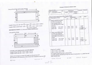
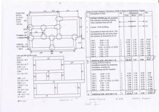
LOAD BEARING STRUCTURE:
Ql. Find out the following quantities from the plan and cross section using long wall
and short wall method.
a) Brick work230 mm thick in CM (1:5) using first class modular bricks of size
200x100x100 in super structure
b) Brick work 480mm thick in CM (1:6) usingfirst class traditional bricks of size
228.6 x 114.3x76.2 inplinth ICL
5.4 x 4.2m
230
Plan GL
I
4
mir
3m
mm
Not to Scale
Centre line dimensions
Z^
600mm
Section
5.63
*t+
1
I
1
1
23C
1
1
.
4
2-30-
L
2m
i
•f1
l
i
l
l
i
i
L
4.43
Length ofCentre line XY= — + 5.4 + — = 5.4 + 0.23= 5.63m
tf £•
Length ofCentre line YZ=^+ 4.2 + ~- = 4.2 +0.23= 4.43 m
Total CL = 2(5.63+4.43)= 20.12 m
Total internal perimeter = 2(5.4 +4.2) - 19.2 m
Total external perimeter = 2(5.86+4.66) =21.04m
R V R K P r a s a d A-126
Did you observe
any relation?
K D K C E , N a g p u r](https://image.slidesharecdn.com/ecunit002new1-230327063407-fafc7048/85/EC-Unit-002-new-1-pdf-1-320.jpg)
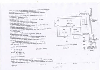
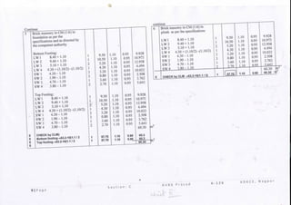
![Continue... (IS 1200) Continue... (IS 1200)
s
N
0
0
0
0
6
0
7
0
0
0
8
0
Description of item
CHECK by CLM
Bottom footing ->49.93-4(0.9/2)
Top footing -»49.93-4(0.7/2)
First class brick work in CM (1:5)
in plinth
Long wall 10.06 + 0.50
Short wall 2 3.83-0.50
CHECK by CLM-»49.93-4(0.5/2)
First class brick work in CM (1:5)
in super structure
Long wall 10.06 + 0.23
Short wall 1 4.13-0.23
Short wall 2 3.83-0.23
Deductions D, W & V
Door, D
Door, Dl
Window, W
Window, Wl
Lintels
Door, D
Door, Dl
Window, W
Window, Wl
CHECK by CLM->49.93-4(0.23/2)
Deductions are same as LW/SW
First brick work in CM(1:5) in
parapet wall-»150 mm thick
LW 10.06 +0.23
SW 7.96+0.23-2(0.15)
CHECK-CL =36.96 -4(0.15)=
No
1
1
^
2
^
1
i)
2
->
o
1
2
2
2
1
2
2
2
1
2
2
1
Dimensions
L(m)
48.13
48.53
10.56
3.63
3.33
48.93
10.29
3.9
3.6
1.2
0.9
1.8
1.2
1.5
1.2
2.1
1.5
49.47
10.29
7.89
36.36
B(m)
0.9
0.7 .
0.5
0.5
0.5
0.50
0.23
0.23
0.23
0.23
0.23
0.23
0.23
0.23
0.23
0.23
0.23
0.23
D/H
0.4
0.4
0.6
0.6
0.6
0.6
^ *>
J.3
t •>
j.3
*> *>
j,3
2.1
2.1
1.5
1.5
0.15
0.15
0.15
0.15
3.3
0.75
0.75
0.75
Qty.
17.327
13.588
3U79T5 i
9.504
2.178
2.997
14.679 !
14.679 r|
23.43
5.92
8.197
(-)0.580
(-)0.869
(-)1.242
(00.828
(-)0.052
(-)0.083
(-)0.145
(00.104
33.646
37.548
(-13.902
33.646
15.435
11.835
27.27
27.27
i
1
I
9
1
1J
nr
m
m
rr
S
N
9
10
11
12
2
Description of item
25 mm thick CC concrete flooring
in 1:2:4 over 100 mm thick
CC(1:4:8)
Drawing
Bed
Kitchen
6 mm thick Ceiling plaster in
CM(1:4)
Drawing
Bed
Kitchen
12 mm thick internal sand -mortar
plaster in CM(1:4)
Drawing 2(9.83 + 3.9)
Bed 2 (5.4 + 3.6)
Kitchen 2(4.2 + 3.6)
Deductions D, W & V
Door, D O/2X1)
Door, Dl 0/2x2)
Window, W (!/2xl)
Window, Wl (l /2 xl)
20 mm thick external pebble dash
plaster in CM (1 :3) up to 15 cm
below GL and includingparapet
All-around perimeter (SS Level)
Length ->36.04 +8(0.23/2)
Height ^-3.3+0.125+0.75
All-around plinth
L=36.04 +4x0.5
Off-set in between1/2(36.96+38.04)
[or 10.56x8.46-10.29x8.19]
No
1
1
1
1
1
1
1
1
1
1
2
2
2
1
1
1
Dimensions
L(m)
9.83
5.4
4.2
9.83
5.4
4.2
27.46
18
15.6
1.2
0.9
1.8
1.2
36.96
38.04
37.5
B(m)
3.9
3.6
3.6
3.9
3.6
3.6
0.135
D/H
-
_
3.3
3.3
3.3
2.1
2.1
1.5
1.5
4.175
0.6
Qty.
38.337
19.44
15.12
72.897 m
38.337
19.44
15.12
7? 8Q7 m
90.618
59.4
51.48
(01-26
(03.78
(01-35
(00.9
194.208
154.308
22.824
5.0625
m'
5 | P a g e S e c t i o n R V R K P r a s a d A - 1 2 6 K D K C E , N a g p u r](https://image.slidesharecdn.com/ecunit002new1-230327063407-fafc7048/85/EC-Unit-002-new-1-pdf-5-320.jpg)
![Continue (IS 1200) Continue (IS 1200)
s
N
13
14
15
16
Description of item
15 cm below foundation
L =36.04+8(0.7/2)
Off-set in btn y2(38.04+38.84)
[10.76x8.66-10.56x8.46]
Inner face of parapet36.96-4x0.15
[36.04 +8x0.40]
Top of parapet V2(36.3 6+36.96)
[10.29x8.19-9.99x7.89=5.454]
Deductions
Door, D C/^xl)
Door, Dl (]/2xO)
Window, W f'/jxl)
~ ' /
Window, Wl C/zxl)
CC (1:2:4) in roof slab
Reinforcement in RCC slab
including bending, binding etc
(By approximate method*) ,
CC (1:2:4) in lintels and chajjas
Lintels
Door, D
Door, Dl
Window, W
Window, Wl
/"^l*«!! -.«
Lnajjas
Door, D
Door, Dl
Window, W
Window, Wl
Reinforcement in Lintels and
chajjas including bending, binding
a+f*
No
1
1
1
1
1
2
0
£r
2
1
»— C
etaile
1
2
2
2
1
2
2
2
i—
Dimensions
L(m)
38.84
38.44
36.36
36.66
1.2
1 8
1 <Q
1.2
10.29
01x10.5
d ->BBS
1.5
1.2
2.1
1.5
1.5
1.2
2.1
1.5
O.Olxl
B(m)
-
0.1
-
0.15
-
-
8.19
34 x785'
Bar Ben
0.23
0.23
0.23
0.23
1.0
1.0
1.0
1.0
383 x785
D/H
0.15
-
0.75
-
2.1
1 S
1 *-J
1.5
0.125
) —*•
lingSch
0.15
0.15
0.15
0.15
0.090
0.090
0.090
0090
o —*
Qty.
3.844
5.499
O1.26
0
~j •
(-)0.9
188.028
10.534
0^*7 l
827kg
Miule
0.052
0.083
0.145
0.104
0.135
0.216
0.378
02"?
1.383 n1
'109kg
m
m
S
N
17
18
.
19
20
Description of item
Sal wood work in door,window
and ventilator frame
6' x4' with 1' horns
Door,D 2(1.2+2.1)+4x0.3
Door, Dl 2(0.9+2.0+4x0.3
. Window,W 2( 1 .8+ 1 .5)+4x0.3
Window, W1 2(1 .2+ 1 .5)+4x0.3
Deodar wood work in shutters of
doors, windowsand ventilators
Including railing and shutters
Door, D
Door, Dl
Window, W
Window, Wl ."'
-i ,
Two coats of paint over one coat
of primer on doors and widows
Door, D (1.3x2)
Door, Dl (L3x2)
Window, W (1.3x2)
Window, Wl (1..3 x2)
Three coats of white wash over all
the internal and external walls
For internal walls (internal plaster)
External walls (External plaster)
No
1
2
2
2
1
l
2
2
2
ii
2
2
2
4 _
^^
Dimensions
L(m)
7.8
7.2
7.8
6.6
1 9
1 i.C
0.9
1.8
1.2
1 9
1 tL,
0.9
1.8
1.2
'.*>
B(m)
0.15
0.15
0.15
0.15
-
-
_
For M20 and Fe 415^0.36 fck xu b = 0.85fy Ast;
,3 ;. 100( Ast/bd)= (36 fck/087fy)(xu/d)-> 0.9572%
slabs Beams incl stirrups
0.75 to 1% 1to 1 .25 %
Columns
1.5to 2% J
D/H
0.1
0.1
0.1
0.1
2.1
•2.1
1.5
1.5
? 1
^*1
2.1
1.5
1.5
»,
•
»,.
"-
Qty.
0.765
2 52
4l9*) L*
3.78
5.4
1 f3
8 5*52
jf*J*}£,
9.828
14.04
9.36
41.78
194.208
188.028
382.236
rn3
1 1 1
m2
m2
_ t
m2
Footings
0.5 to 0.75%
6 | P a g e S e c t i o n R V R K P r a s a d A - 1 2 6 K D K C E , N a g p u r](https://image.slidesharecdn.com/ecunit002new1-230327063407-fafc7048/85/EC-Unit-002-new-1-pdf-6-320.jpg)
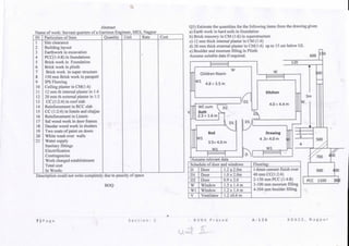
![Q4. Prepare a detailed estimate of a load bearing structure of a traveler's bun glow
of Road & Building Dept. The drawings show the plan and section of the building.
600
115
450
o,
80 600
t
600
GL 1
/t
/600
750
Section
3.1m
FL
Wl
V
Bath
1.79 x
2.73m
Dl
F 3ae
we
&..25X
1.5m
Dl
31 1m
1m
* +
passage
Kitchen
3.0x3.5m
W
2.96
Drawing
4.5 x 4.0 m
Bed
3.5 x 3.5m
W
4.23
2.02m 1.48m 1.23m
Bath
1.79 x
2.73m
we
1
1.25 x
1.5m
1.4R
i
1m
m
'
Drawing
4.5 x4.0m
3.23
Kitchen
3.Ox 3.5m
3.73
Bed
3.5x3.5m
4.73
1.57m
8.46 3.73
±^46
3.73
1.57m
Wl
1:4:8
900
Wl ! Plan
1.57m
All dimensions are in mm
r
"unless specified
Not to Scale
Schedule of Doors, Windows & V
D
Dl
W
Wl
V
Door
Door
Window
Window
Ventilator
1.2mx 2.1m
0.9m x 2.1 m
1.8 m x 1.5 m
1.5 mx 1.5m
0.8 m x0.6m
All walls are of 230 mm thick
Passage is 1m wide.
Lintel :- 230 x 150mm - bearing: 300 mm
Chajja:- 1.0m wide- 100-80 mm thick
Additional 300 mm on either side of opening
wherever available
IVU2 LW
SW2
SW1
bwl
LA/4
SW3
CL length = 2(7.46)+7.19+l.57+2.96+1.73+2 (8.46)+7.96+1.48 = 54.73 [T ->10]
•--Outer perimeter (around walls at superstructure) = 54.73+4x0.23 = 55.65 m
Rear side Offset: 7.46 +1.57 - 7.19 = 1.84m
Long wall and short walls
LW1->7.19+0.23 = 7.42 ^ S&LL
LW2-»2.96-0.23 =2.73
LW3->1.73+ 0 -1.73
LW4-»9.03+0.2 3= 9.26
: LW5-^3.73+ 0 = 3.73
LW6-»3.73 +0.23 =3.96
ILW= 28.83
SWl-»4.73-0.23=4.50
SW2->1.48-0.23=1.25
SW3^3.23-0.23=3.00
SW4-^3.73-0.23=3.50
ESW =12.25
241.08+12.5=53.58
CHECK-*53.58+l.15
SW4
LW6
10 | Pa ge S e c t i o n : C R V R K P r a s a d A - 1 2 6 K D K C E , N a g p u r](https://image.slidesharecdn.com/ecunit002new1-230327063407-fafc7048/85/EC-Unit-002-new-1-pdf-10-320.jpg)
![Bar BendingSchedule
In RCC works Concrete and Steel are calculated separately
Development length for Reinforcing steel,/d = ( ) x 0.87
bond stress, ibd
InMPa
M20
1.2
M25
1.4
M30
1.5
M35
1.7
>M40
1.9
For deformed bars conforming to IS 1786 these values shall be increased by 60 %
For bars in compression, values of ibd for bars in tension shall be increased-by 25%
For M20 Grade Concrete with Mild (Fe250) Steel:
In Tension
d
xO.87 X250
4(1-2)
= 45.3<p
InCompression
(px 0.87x250
la 4(1.25 x 1.2)
= 36.25<p
For M20 Grade concrete with HYSD(Fe 415) (Tor/CTD) Steel:
In Tension
<px 0,87x415
ld 4(1.6X1.2) 47<P
In Compression
<px 0,87x415
a 4(1.25 X1.6X1.2) " ' ^
a) Deformed bars may be used without end anchorages provided development length
requirement is satisfied.Hooks should normally be provided for plain bars intension
b) Bends and hooks - Bends and hooks shall conform to IS 2502
1) Bends- The anchorage value of bend shall be taken as 4 times the diameter of the
bar for each 45° bend subject to a maximum of 16times the diameterof the bar.
X 4(t> X ;
.
V l length required beyond X: 13.137^)^13^ Addl. len., X: 4.927O~5d>
2) Hooks-The anchorage value of a standard U-type hook shall be equal to 16
times the diameter of the bar.
c) Stirrups-Notwithstanding any of the provisionsof this standard, in case of
secondary reinforcement,such as stirrups and transverseties, complete development
lengths and anchorage shall be deemed to have been provided ->when the bar is
bent throughan angle of at least 90° round a bar of at least its own diameter and is
continued beyond the end of the curve for a length of at least 8O, or when the bar is
bent through an angle of 135° and is continued beyond the end of the curve for a
length of at least 6^> or when the bar is bent through an angle of 180° and i£
continued beyond the end of the curve for a length of at least 4O.
Bent Up Bars:-
For 45° bend; y = x =D-dc-d1 or d-d' & z = x>/2 = 1 .414 x
;.z - x= 0.414 x -> Additional length of bent up bar over the straight bar.
Ql . Prepare a detailed estimate for the quantity of steel in RCC beam 400 x 750 mm
over a clear span of 6m, with support width 230mm. 8mm<£ 2 legged vertical
stirrups at 250mm c/c. Two bars of main steel are bent up. Nominalcover =
' '
1 I
230
i
J a.
"YYTf*" 204>
A1. Schedule of bars (BBS)
1
2
3
4
Descriptio
n of bar
Main steel
bar
Main steel
Bent up
bar
Anchor
bar
Stirrups
Shape of bar
1 1
^-^
>
of
bar
20
20
12
8
Leng
thof
bar
6.920
7.464
6.722
2.156
No.
of
bar
2
2
2
26
Tot
Len
(m)
13.84
14.93
13.44
56.05
Unit
wt
2.47
2.47
0.89
0.39
Wt
m
34.2
36.9
12.0
21.9
Total
Wt.
(kg)
105
VP
7850]
P a g e S e c t i o n : C
Unit wt = 4>2/162.196 [fix
Length ofmain steel straight bar =6000+2x230 -2x30 + 2x13x20 - 6920mm
R V R K P r a s a d A - 1 2 6 K D K C E , N a g p u r](https://image.slidesharecdn.com/ecunit002new1-230327063407-fafc7048/85/EC-Unit-002-new-1-pdf-13-320.jpg)
![Effective cover to main steel, dc= 30+8+20/2 =48mm
Effective cover to anchor bars =30+8+12/2 = 44mm but due to bent ups, d' =48mm
C/C distance between straight and bent up bars (near supports)-750-2x48=654 mm
Length of bent up bar = 6920 +(2x0.414x654)=7464 mm
Length of anchor bar -6000+2x230 -2x25 + 2x13x12- 6722 mm
No of stirrups (6000+2x230)/250 =25.84 = 26 (Next integer value)
Length of bar for 135° stirrup: 2[(400-60-8)+(75Q-60+8)]+2(8x8)=2.156m
St. in y-dir
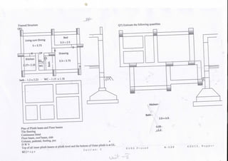
calculate the quantitiesof steel and concrete in a column
and footing as shown. The column is of 230 x 350mm.
Depth of footing is 600mm at the face of column at 200
mm at the free end. The size of footing is 2.68 x 2.8 m at
bottom and 280 x 400mm at top. PCC is 150mm thick
with an offset of 200mm on either side of footing.
B
% •f |L_±
1
T
38m
SSS
1200
=ul 60°
150
Column is reinforced with 4 nos of 16 mmO with transverse reinforcement is of 8
mmO @ 150 mm c/c. Footing is reinforced with 10 mm <t> 175 mm c/c both ways
A2. =>Quantity of concrete in Trapezoidal portion, V = f r * T B—-1h
s
N
1
2
•1
4
Description of item
Earthwork excavation
PCC (1:4:8)
CC(1 :l'/2:3)in RCCfooting
a) Rectangular portion
b) trapezoidal 2.68x2.8+^(2:
portion
CC(l:r/2:3)inRCCColumn
N
0
1
1
I
>8x2.E
1
1
Dimensions
L
3.2
3.2
2.68
x0.23*<
3 •*—
0.23
B
3.08
3.08
2.8
35)+0.23x
-2.78 -*•
0.35
D/H
1.95
0.15
0.2
0.3E 0.4
5.0
Qty.
19.22
1.48
1.50
1.115
0.4
Total
19.22m3
1.48m3
2.615m-1
0.40 m3
Bar Bending Schedule - Schedule of bars
1
2
^
4
Descriptio
n of bar
Main steel
in column
Lateral
ties
Footing
St. in x-dir
Footing
Shape ofb
l_
1
ir
i
1 1
0
16
8
10
10
Leng
bar
6.07
1.0
2.63
2.75
No.
bar
4
38
16
15
Tot
Len
24.28
38
42.08
41.3
Unit
wt
1.58
0.39
0.62
0.62
Wt
in
38.4
14.8
26.1
25.6
Total
W-kg
'105
| P a g e S e c t i o n : C
Column: Dev.Len. for the main steel in column,la = — —-- = 37.60= 601
• -
Available = 600 -75 = 525 mm; extra required = 601-525 = 76 mm
Provide a min. extra length of 450mm. to facilitate erection of reinforcement.
Length of column main steel =(5600-40-75-10-10/2-16/2)+450+2(5xl6)=6072mm
Length of lateral ties(135°)=2[(230-80+8)+(350-80+8)]+2(8x8)=1000mm
No. of ties = 5600/150 =37.33 = 38 (Next integer value)
$7X0.87X415
Footing: Id for footing bars - ld =
4(1.6X1.2)
Length of bar in x-direction: 2680 -150 +2(5x10) =2630mm
No of bars - (2800-150)/175 -15.14 say 16 No.
Length of bar in x-direction: 2800 -150 +2(5x10) =2750mm
No of bars - (2680-150)/175 -14.45 say 15 No
= 47<p = 470mm <1455 (1575) OK
ftV->- rrepare a aeiauea estimate 01 a one
way RCC Roof slab over a room of 3x7m
clear dimensionsand support width is
230mm. Slab is 125 mm thick. Main steel is
10mm<D @ 125 mm c/c alternate bent up.
Distribution steel is of 6mm<I> (2J 150 c/c Nomira
—i
7_ •
tj
—'
1 cover = 1 5 mm, End C=25
A3.=> B.B.S. Length of min steel (straight) =3000+2x230 -2x25 + 2x5x10 =3510
C/C dist. between straight and bent up bars (near supports)= 125-2x( 15+5)=85mm
Length of bent up bar = 3510 +(2x0.414x85)=3580 mm
No of bars = (7460-50)/!25=46.3 = 61 (31 straight and 30 bent up)
Length of bar Distribution reint. bar-7000+2x230 -2x25 = 7410mm
No of bars - (3460-50)/! 50=23
1
2
"
Descriptio
n of bar
Main steel
straight
bar
Main steel
Bent up
bar
Distributio
n bars
Shape of bar
1 1
^—^
>
10
10
6
Leng
th
3.51
3.58
7.41
No
bar
31
30
23
Tot
Len
108.8
107.4
168.5
Unit
wt
0.62
0.62
0.22
Wt
in
67.5
68.6
37.1
Total
W(kg
173.2
kg
Area of slab= 3.46 x 7.46 =25.81m2; 173.2/25.81 =6.71kg/rrTor 0.62 kg/sft
R V R K P r a s a d A - 1 2 6 K D K C E , N a g p u r
v>M](https://image.slidesharecdn.com/ecunit002new1-230327063407-fafc7048/85/EC-Unit-002-new-1-pdf-14-320.jpg)
![# Q4. Determine the quantity of steel in an
interior 1 15 mm thick RCC Two way roof
support width is 230mm. The main steel is 8
mm<t> @ 175 mm c/c in shorter direction &8
mm <X> @ 200 mm c/c in longer direction,
both the steels are bent-up alternately. Extra
tops are of 1 OmmO extended up to 0.3 1(both
directions and both ways). Calculate for the
slab area based on Centre line dimensions.
r —~
/
•*.
-
1——
4.8m fc
i
ii
—i-
i
i
i
~1
*** In this steel requirement for this slab only on Centre line basis (3.83x5.08m)
was calculated.
Areaofslab:3.83 x 5.03 = 19.2649 m2 = x 10.764 =207.37 sft.
.2
A4. => Both direction steels are of main steel in #
Torsional reinforcement is not needed in this interior panel [lx/5- 3/4 Astsl/ve-4 layer]
Assuming the reinforcementin middle strips and edge strips are same [ 1/8 ]
Reinforcement in:
Length of straight bars
Length bent up bars
No of bars:
Length of Extra tops
Shorter direction
3600+230 - 3830mm
3830+2x0.414x77=3894
(4800+230)/175=29(15+14)
0.3*3830+5*10-1199(15)
longer direction:
4800+230 -5030mm
5030+2x0.414x69-5087
(3600+230)/200=20( 10+10)
0.3*5030+5*10=1559(10)
Extra tops are assumed to be provided exactly over the straight bars (* alternate)
Bar BendingSchedule:
A
1
2
3
B
I
2
3
Descriptio
n of bar
Shape of bar <p
bar
Leng
th(m)
No. Tot
Len
Unit
wt
Wt
in
Shorter span
straight
bar
Bent up
bar
Extra-tops
1 ;
•K /t"
i
r+
8
8
10
3.83
3.89
1.2
15
14
2x
15
57.5
54.5
36
0.39
0.39
0.62
22.4
21.3
22.3
Longer span ' '
straight
bar
Bent up
bar
Extra-tops
,_ i
*-t
-1—i H-
8
8
10
5.03
5.09
1.56
10
10
2x
10
50.3
50.9
31.2
0.39
0.39
0.62
19.6
19.8
19.3
Total
W(kg
124.7
kg
Quantity of steel/sft - 124.7/207.37 = 0.6 kg./sft
ForInformation:-
Bent up and extra top lengths:
or 6.47 kg/m .
Requirement of IS 456
Discontinuous edge
Continuous edge
Bent up
<0.15l
< 0.25 I
Extra top
*> 0.11 (50%of+veif req)
> 0.3 1(0.151-50% + 0.31 -50%)
S e c t i o n : C R V R K P r a s a d A - 1 2 6 K D K C E , N a g p u r](https://image.slidesharecdn.com/ecunit002new1-230327063407-fafc7048/85/EC-Unit-002-new-1-pdf-15-320.jpg)

The document provides details on methods of building estimation including the long wall-short wall method, centre line method, and crossing method. It explains how to calculate the lengths of long walls and short walls using these methods, accounting for wall thickness. The centre line method sums the lengths of all walls along their center lines and makes corrections for junctions. The crossing method combines the centre line and long wall-short wall methods to measure outer walls by centre line and internal walls separately. In summary, the document outlines three common methods for estimating building quantities and calculating wall lengths.


