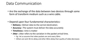
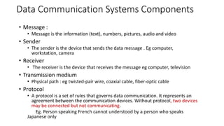
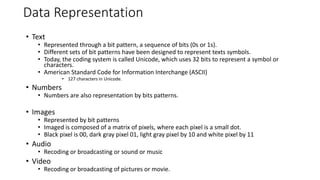
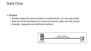
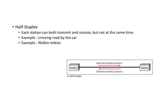
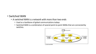
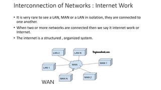
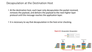
The document provides an overview of data communication and networking concepts. It discusses data communication fundamentals including delivery, accuracy, timeliness and jitter. It describes data communication system components such as messages, senders, receivers, transmission medium and protocols. It also covers data representation, data flow models, network types including LAN, MAN and WAN, wireless networks, internet interconnection and network protocols and standards.
2. Data Communication
• Are the exchange of the data between two devices through some
form of transform medium such as a wire cable.
• Depend upon four fundamental characteristics:
• Delivery : Deliver data to the correct destination.
• Accuracy : The system must deliver the data accurately
• Timeliness : time is matter
• Jitter : Jitter refers to the variation in the packet arrival time.
• Eg : let us assume that video packets are sent every 30ms
• Others are sent 30-ms delay and other 40ms delay than quality of video decreases
3. Data Communication Systems Components
• Message :
• Message is the information (text), numbers, pictures, audio and video
• Sender
• The sender is the device that sends the data message . Eg computer,
workstation, camera
• Receiver
• The receiver is the device that receives the message eg computer, television
• Transmission medium
• Physical path : eg twisted-pair wire, coaxial cable, fiber-optic cable
• Protocol
• A protocol is a set of rules that governs data communication. It represents an
agreement between the communication devices. Without protocol, two devices
may be connected but not communicating.
Eg. Person speaking French cannot understood by a person who speaks
Japanese only
4. Data Representation
• Text
• Represented through a bit pattern, a sequence of bits (0s or 1s).
• Different sets of bit patterns have been designed to represent texts symbols.
• Today, the coding system is called Unicode, which uses 32 bits to represent a symbol or
characters.
• American Standard Code for Information Interchange (ASCII)
• 127 characters in Unicode.
• Numbers
• Numbers are also representation by bits patterns.
• Images
• Represented by bit patterns
• Imaged is composed of a matrix of pixels, where each pixel is a small dot.
• Black pixel is 00, dark gray pixel 01, light gray pixel by 10 and white pixel by 11
• Audio
• Recoding or broadcasting or sound or music
• Video
• Recoding or broadcasting of pictures or movie.
5. Data Flow
• Simplex
• Simplex mode, the communication is unidirectional , as a one-way street.
• Only one of the two devices on a link can transmit; other can only receive
• Example : keywords and traditional monitors
6. • Half-Duplex
• Each station can both transmit and receive, but not at the same time.
• Example : crossing road by the car
• Example : Walkie-talkies
7. • Full-Duplex
• Called also duplex
• Both stations can transmit and receive simultaneously
• Example : telephone network
8. Network
• A network is the interconnection of a set of devices capable of
communication.
• A device can be a host(e.g computer , desktop, laptop, cellular phone)
• A network must be able to meet certain number of criteria.
• The most important of these are :
• Performance :
• Measured in many ways, including transit time and response time.
• Reliability
• Is measured in frequency of failure, the time it takes a link to recover from a failure
• Security
• Network security issues include protecting data from unauthorized access
• Protecting data from damage and development
9. Physical Structures
• Types of connection
A network is two or more devices connected through the links.
• Point to Point
• Provides a dedicated link between two devices
• The entire capacity of the link is reserved for transmission between these two devices.
• Wire or cable
Example : while changing the channel from remote to TV, satellite link
• MultiPoint
• Is one in which more than one specific devices share the single link
11. • Mesh Topology
• Every device has dedicated point to point link to every other
• Dedicated means link carries traffic only between the two devices it
connects.
• Find the physical links in a fully connected mesh networks with n nodes
• Node 1 must connected to n-1 nodes
• Node 2 must be connected to n-1 nodes
• Node n must be connected to n-1 nodes
• We need n(n-1) physical links.
• If both directions duplex mode than n(n-1)/2
12. Advantage
• Dedicated link guarantees that each connection can carry its own
data load.
• Helps to eliminating the traffic problems
• If one link becomes unusable, it does not incapacitate the entire
system
• Advantage of having privacy or security
• Helps to find fault identification and fault isolation easy.
• Traffic can be routed to avoid links
13. Disadvantage
• The main disadvantage of a mesh are related to the amount of cabling
and number of I/O ports
• Every device need to connected
• Sheer bulk of wiring can be greater than the available space can
accommodate
• Hardware required to connect I/O
• Therefore mesh topology is usually implemented in a limited fasion.
14. Star topology
• Have connections to networked devices that “radiate” out form a
common point
• Each networked device in star topology can access the media
independently
• Have become the dominant topology type in contemporary LANs
• Stars have made buses and rings obsolete in LAN topologies
14
15. Advantages of star topology
1) Compared to Bus topology it gives far much better performance
2) Easy to connect new nodes or devices
3) Centralized management. It helps in monitoring the network
4) Failure of one node or link doesn’t affect the rest of network
15
16. Disadvantages of star topology
1) If central device fails whole network goes down
2) The use of hub, a router or a switch as central device increases the
overall cost of the network
3) Performance and as well number of nodes which can be added in
such topology is depended on capacity of central device
16
17. Bus topology
• All networked nodes are interconnected, peer to peer, using a single,
open-ended cable
• Both ends of the bus must be terminated with a terminating resistor
to prevent signal bounce
17
18. Advantages of Bus topology
1) Easy to implement and extend
2) Well suited for temporary networks that must be set up in a hurry
3) Typically the least cheapest topology to implement
4) Failure of one station does not affect others
18
19. Disadvantages of Bus topology
1) Difficult to administer/troubleshoot
2) Limited cable length and number of stations
3) A cable break can disable the entire network; no redundancy
4) Maintenance costs may be higher in the long run
5) Performance degrades as additional computers are added
19
20. Ring topology
• started out as a simple peer-to-peer LAN topology
• Data was transmitted unidirectionally around the ring
• Sending and receiving of data takes place by the help of TOKEN
• Token contains a piece of information which along with data is
sent by the source computer
• This token then passes to next node, which checks if the signal is
intended to it
If yes, it receives it and passes the empty to into the network
otherwise passes token along with the data to next node
20
21. Advantages of Ring topology
1) This type of network topology is very organized
2) No need for network server to control the connectivity
between workstations
3) Additional components do not affect the performance of
network
4) Each computer has equal access to resources
21
22. Disadvantages of Ring topology
1) Each packet of data must pass through all the computers
between source and destination, slower than star topology
2) If one workstation or port goes down, the entire network gets
affected
3) Network is highly dependent on the wire which connects
different components
22
23. Network types :
• Local Area Network (LAN)
• Less than 1 km in range
• 10 mbps – 1 Gbps – data flow capacity
• Within Room Building Campus
LAN or Local Area Network connects network devices in such a way that personal
computer and workstations can share data, tools and programs.
The group of computers and devices are connected together by a switch, or stack
of switches, using a private addressing scheme as defined by the TCP/IP protocol.
Private addresses are unique in relation to other computers on the local network.
Routers are found at the boundary of a LAN, connecting them to the larger WAN
24. • Metropolitan Area Networks (MAN)
• Size between a LAN and WAN (Within city area)
• 1-10 kms in range
• Data flow capacity is less than LAN
• Combination of Multiple LAN’s
• High Speed Wireless Internet access has been standardized
• Example Cable TV network
MAN or Metropolitan area Network covers a larger area than that of a LAN and
smaller area as compared to WAN.
It connects two or more computers that are apart but resides in the same or
different cities. It covers a large geographical area and may serve as an ISP (Internet
Service Provider).
25. WAN
• 100 Km -1000 km
• Data flow less than MAN
• Combination of multiple LAN’s or
MAN’s
• Hosts are connected by a
communication subnet.
• Subnets consist of many routers
• Images, audio and video information
over the
large geographic areas
WAN or Wide Area Network is a computer network that extends over a large geographical area, although it
might be confined within the bounds of a state or country.
A WAN could be a connection of LAN connecting to other LAN’s via telephone lines and radio waves and
may be limited to an enterprise (a corporation or an organization) or accessible to the public.
The technology is high speed and relatively expensive.
26. • Two example of WANs today
• Point to point WAN
• A point –to point WAN is a network that connects two communicating devices through
the mission media (Cable, air)
• Network connecting in different network.
27. • Switched WAN
• A switched WAN is a network with more than two ends
• Used as a backbone of global communications todays
• Switched WAN is a combination of several point-to-point WANs that are connected by
switches.
28. Wireless Network
• System Interconnection : Interconnecting the components of a
compute using short range radio. Wireless mouse , keyword
• Wireless LAN’s
• Wireless WAN’s
29. Interconnection of Networks : Internet Work
• It is very rare to see a LAN, MAN or a LAN in isolation, they are connected to
one another.
• When two or more networks are connected then we say it internet work or
Internet.
• The internet is a structured , organized system.
30. Protocols and Standards
• Protocols :
• In computer networks, communication occurs between entities in
different systems.
• An entity is anything capable of sending or receiving information.
• Two entities cannot simply send bit streams to each other and expect to
be understand
• for communication to occur the entities must agree on a protocol which is a set of
rules that govern data communication.
31. • Key elements of protocols are:
• Syntax: It refers to the structure or format of data, meaning the order in
which they are presented.
• Semantics : The word semantics refers to the meaning of each section of bits.
The pattern of bits must be correct.
• Timing : It refers to the two characteristics :
• When data should be sent and how fast they can be sent.
32. Standards
• Standard provide guidelines to manufactures, venders, government agencies
and other service providers to ensure the kind of interconnectivity necessary
is today’s marketplace and international communications.
• Some organizations that set standards are:
• International Organization for Standardization (ISO)
• International Telecommunication Union - Telecommunication Standard
Sector (ITU-T)
• American National Standards Institute (ANSI)
• Institute of Electrical and Electronics Engineer (IEEE)
35. Layered Tasks
• Layered task, play vital role to accomplished the task successfully.
• Lets take an example,
• Each layer at the
site uses the services
of the layer immediately
below.
37. • A network is a combination of hardware and software that
sends data from one location to another.
• Hardware consists of physical equipments that carries
signals from one point of the network to another.
• Software consists of instruction sets that make possible
the services that is expected from networks
38. Protocol Hierarchies :
• To reduce their design complexity, most networks are organized as a stack
of layers or levels, each one built upon the one below it.
• Instead, each layer passes data
and control information to the
layer immediately below it, until
the lowest layer is reached.
• No data are directly transferred
from the layer “n” or one
machine to layer “n” of other
machine.
39. Protocol Hierarchies :
•Interface
•Defines which primitive
operations and services the
lower layer makes available to
the upper level.
•A set of layers and protocols is
called network architecture.
40. Design Issues for the layers
• Addressing :
• Every layer needs a mechanism for identifying senders and receivers.
• Since a network has many computers, it needs some sort of addressing for
the accurate delivery of the message.
• Error Control:
• There must be some kind of error control mechanism.
• Receivers must have some way of telling the sender which message have
been correctly received and which have not .
• Flow Control :
• There must be some kind of mechanism for flow control in order to
guarantee that sent message has been received.
• There might be a case like the sender in fast and the receiver in slow.
41. Multiplexing:
• Using multiple channel in a single link in order to
maximum utilization of available bandwidth of the
medium.
Routing:
• When there are multiple paths between sender and receiver, then
a route must be chosen for the fast and efficient transmission.
42. Connection Oriented and Connection less Services:
• Connection Oriented:
• It is modeled after telephone system
• Service user first established and connection, use the
connection and then release the connection.
• It acts like a tube
• Connectionless :
• It is modeled after postal system.
• Each message carries the full destination address and each one
is routed through the system independent of all the others.
43. Reference Model
• It is a standard reference model for communication between two
end users in a network.
• It deals with connecting open system ie, system that are open for
communication with other system.
44. Open Systems Interconnection (OSI)
The OSI Model
• The purpose of the OSI model to facilitate communication
between different systems without requiring changes to the logic
of the underlying hardware and software.
• The OSI model is not a protocol; it is a model for understanding
and design of network.
• The OSI model is a layered framework for the design of network
systems that allows communication between all types of
computer systems.
• It consists of seven separate but related layers, each has
responsibility for the process of moving information across a
network.
47. Layered Architecture
• Peer to Peer Processes
• Between machines, layer “x” on one machine communicates with
layer “x” on another machine. This communication is governed by
an agreed-upon series of rules and conventions called protocols.
• The processes on each machine that communicate at a given layer
are called peer-to-peer processes.
• Interface
• Defines which primitive operations and services the lower layer
makes available to the upper level.
• A set of layers and protocols is called Network Architecture
48. • Layers 5,6,7 are the user support layers: Allows interoperability
among unrelated software systems
• Layer 4 links these two subgroups and ensure that what the lower
layers have transmitted is in a form that the upper layers can use.
Organization of Layers
The seven layers can be thought of as
belonging to three subgroups.
Layer 1,2,3 are the network support
layers ;
deal with physical aspects of
moving data from one device to
another
(such as electrical specifications,
physical connections, physical
addressing and transport timing
and reliability)
49. Application Layer
• The application layer enables the user, whether human or
software, to access the network.
• It Provides user interfaces and support for services such as
electronic mail, remote file access and transfer.
• Applications on that layer (E-mail clients, web browsers, Chats,
etc.) – top-stack applications (As people are on the top of the
stack)
50. Presentation Layer :
• Presentation layer is also called the Translation layer.
• The data from the application layer is extracted here and
manipulated as per the required format to transmit over the
network.
The functions of the presentation layer are :
• Translation : For example, ASCII to EBCDIC (Extended Binary Coded
Decimal Interchange Code).
• Encryption/ Decryption : Data encryption translates the data into another
form or code. The encrypted data is known as the cipher text and the
decrypted data is known as plain text. A key value is used for encrypting as
well as decrypting data.
• Compression: Reduces the number of bits that need to be transmitted on
the network.
51. Session Layer
• This layer is responsible for establishment of connection, maintenance
of sessions, authentication and also ensures security.
• The functions of the session layer are :
• Session establishment, maintenance and termination: The layer allows
the two processes to establish, use and terminate a connection.
• Synchronization : This layer allows a process to add checkpoints which are
considered as synchronization points into the data. These synchronization point
help to identify the error so that the data is re-synchronized properly, and ends
of the messages are not cut prematurely and data loss is avoided.
• Dialog Controller : The session layer allows two systems to start communication
with each other in half-duplex or full-duplex.
• All the below 3 layers(including Session Layer) are integrated as a single
layer in the TCP/IP model as “Application Layer”.
53. Session Layer (Cont..)
• Lets suppose,
• a system sends 1000 page of file.
• It is advisable to insert checkpoints after every 100 pages to
ensure that each
• 100 pages unit is received and acknowledges independently.
• In this case if a crash happens during the transmission of page
after 535.
• The only pages that need to be resent after system recovery are
pages 501 to be resend.
54. • Transport layer provides services to session layer and takes services from network
layer.
• The data in the transport layer is referred to as Segments.
• At sender’s side:
• Transport layer receives the formatted data from the upper layers, performs Segmentation
and also implements Flow & Error control to ensure proper data transmission.
• It also adds Source and Destination port number in its header and forwards the segmented
data to the Network Layer.
• Note: The sender need to know the port number associated with the receiver’s application.
• Generally, this destination port number is configured, either by default or manually. For
example, when a web application makes a request to a web server, it typically uses port
number 80, because this is the default port assigned to web applications. Many
applications have default port assigned.
• At receiver’s side:
• Transport Layer reads the port number from its header and forwards the Data which it has
received to the respective application. It also performs sequencing and reassembling of the
segmented data.
Transport Layer:
55. • The functions of the transport layer are :
Segmentation and Reassembly:
• This layer accepts the message from the (session) layer , breaks the
message into smaller units .
• Each of the segment produced has a header associated with it.
• The transport layer at the destination station reassembles the message.
Service Point Addressing:
• In order to deliver the message to correct process, transport layer header
includes a type of address called service point address or port address.
• Thus by specifying this address, transport layer makes sure that the
message is delivered to the correct process.
56. • The services provided by the transport layer :
• Connection Oriented Service: It is a three-phase process which include
• Connection Establishment
• Data Transfer
• Termination / disconnection
• In this type of transmission, the receiving device sends an acknowledgement, back to the
source after a packet or group of packet is received. This type of transmission is reliable and
secure.
• Connection less service:
• It is a one-phase process and includes Data Transfer.
• In this type of transmission, the receiver does not acknowledge receipt of a packet.
• This approach allows for much faster communication between devices.
• Connection-oriented service is more reliable than connectionless Service.
Data in the Transport Layer is called as Segments.
Transport layer is operated by the Operating System. It is a part of the OS and communicates with the
Application Layer by making system calls.
57. • The network layer is responsible for creating a connection between the source computer and
the destination computer.
• It also takes care of packet routing i.e. selection of the shortest path to transmit the packet,
from the number of routes available.
• The sender & receiver’s IP address are placed in the header by the network layer.
• The functions of the Network layer are :
• Routing: The network layer protocols determine which route is suitable from source to
destination. This function of network layer is known as routing.
• Logical Addressing: In order to identify each device on internetwork uniquely, network
layer defines an addressing scheme. The sender & receiver’s IP address are placed in the
header by network layer. Such an address distinguishes each device uniquely and
universally.
• Segment in Network layer is referred as datagram. Network layer is implemented by
networking devices such as routers.
Network Layer:
58. • The main function of this layer is to make sure data transfer is error-free from one node to
another, over the physical layer.
• When a packet arrives in a network, it is the responsibility of DLL to transmit it to the Host
using its MAC address.
• The packet received from Network layer is further divided into frames depending on the frame
size of NIC(Network Interface Card). DLL also encapsulates Sender and Receiver’s MAC address
in the header.
• The Receiver’s MAC address is obtained by placing an ARP(Address Resolution Protocol)
request onto the wire asking “Who has that IP address?” and the destination host will reply
with its MAC address.
Data Link Layer
59. • The functions of the data Link layer are :
• Framing: Framing is a function of the data link layer. It provides a way for a sender to transmit a set of
bits that are meaningful to the receiver. This can be accomplished by attaching special bit patterns to
the beginning and end of the frame.
• Physical addressing: After creating frames, Data link layer adds physical addresses (MAC address) of
sender and/or receiver in the header of each frame.
• Error control: Data link layer provides the mechanism of error control in which it detects and
retransmits damaged or lost frames.
• Flow Control: The data rate must be constant on both sides else the data may get corrupted thus , flow
control coordinates that amount of data that can be sent before receiving acknowledgement.
• Access control: When a single communication channel is shared by multiple devices, MAC sub-layer of
data link layer helps to determine which device has control over the channel at a given time.
Packet in Data Link layer is referred as Frame.
Data Link layer is handled by the NIC (Network Interface Card) and device drivers of host machines.
Eg. Switch & Bridge are Data Link Layer devices.
Data Link Layer
60. Physical Layer:
• The lowest layer of the OSI reference model is the physical layer.
• It is responsible for the actual physical connection between the devices. The
physical layer contains information in the form of bits.
• It is responsible for transmitting individual bits from one node to the next.
• When receiving data, this layer will get the signal received and convert it
into 0s and 1s and send them to the Data Link layer, which will put the
frame back together.
61. • The functions of the physical layer are :
• Bit synchronization: The physical layer provides the synchronization of the
bits by providing a clock. This clock controls both sender and receiver thus
providing synchronization at bit level.
• Bit rate control: The Physical layer also defines the transmission rate i.e.
the number of bits sent per second.
• Transmission mode: Physical layer also defines the way in which the data
flows between the two connected devices. The various transmission
modes possible are: Simplex, half-duplex and full-duplex.
• Hub, Repeater, Modem, Cables are Physical Layer devices.
Physical Layer:
62. TCP/IP Protocol Suite
• This protocol was developed prior to OSI
layer
• It has five layers
• TCP/IP is a protocol suite used in the
Internet today.
• Missing session and presentation
63. TCP/IP Protocol Suite 63
Figure 2.15 Addresses in the TCP/IP protocol suite
Application layer -> someorg.com or email address
Transport layer port numbers
port numbers are local addresses
Network-layer address addresses are global, with the whole Internet as the scope
Data-link layer address MAC addresses
are locally address, each of which defines a specific
host or router in a network (LAN or WAN)
66. OSI model vs TCP/IP
• The OSI model appeared after the TCP/IP protocol suite.
• Most experts thought that the TCP/IP protocol would be fully replaced by the OSI
model.
• This didn’t happen
• There were three reasons (agreed by experts)
• OSI was completed when TCP/IP was fully in place and a lot of time and money
has been spent which results changing would cost a lot of money
• Some layers were not fully defined such as presentation and session layer.
• When OSI was implemented by an organization in a different application, it
didn’t show a high enough level of performance to entice the Internet
authority to switch from the TCP/IP protocol suite to the OSI model
68. • Network Layer : takes the transport – layer
packet as data or payload.
• Adds its own header to the payload.
• The header contains the addresses of the
source and destination hosts and some
more information used for error checking
for the header.
• The result is the network-layer packet
called as datagram.
• The network layer packets transfer to the
data link layer.
At the application layer : message (does not contain any header or trailer)
Transport layer : takes message as the payload
Adds as transport layer header to the payload which contains the identifiers of the source
and destination application programs
Transport-layer packet is called segment in (TCP) and the user datagram (in UDP)
The transport layer then passes the packet to the network layer.
Encapsulation at the Source Host
69. • Data-link layer takes the network layer packet as data and its own header
which contains link layer address of the host or next hob (router).
• The link layer packet is called as frame.
• The frame is passed to the physical layer for the transmission.
70. Decapsulation and Encapsulation at the Router
• Router has encapsulation as well as decapsulation.
• After sets of bits are delivered to the data-link layer , this layer decapsulates
the datagram from the frame and passes it to the network layer.
• Network layer just inspect the source and destination address in the
datagram header and consults its table to forward to the respective hob.
• The datagram should not be changed by the network layer in the router
unless there is a need to fragment the datagram if it is too big.
71. Decapsulation at the Destination Host
• At the destination host, each layer only decapsulates the packet received,
removes the payload, and delivers the payload to the next-higher layer
protocol until the message reaches the application layer.
• It is necessary to say that decapsulation in the host error checking.