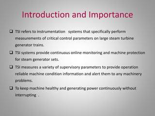
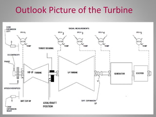
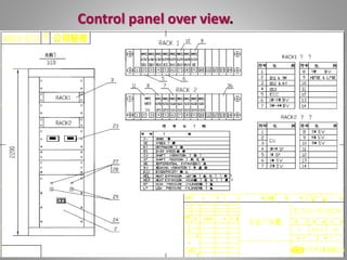
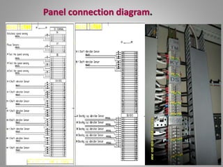
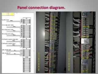
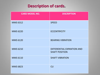
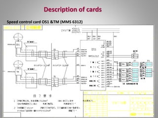
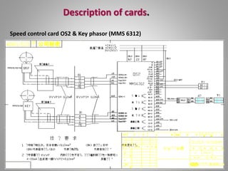
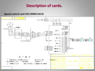
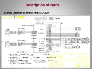
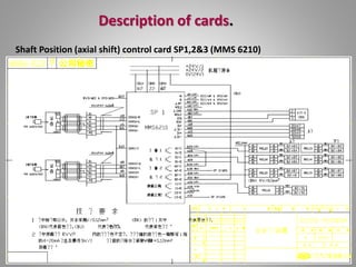
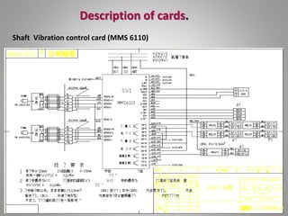
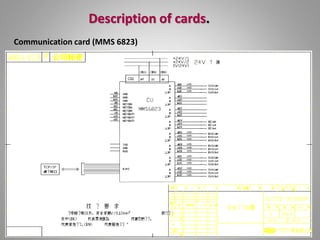
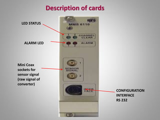
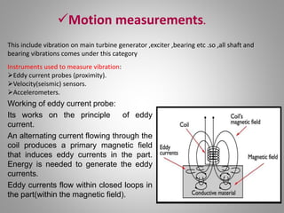
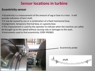
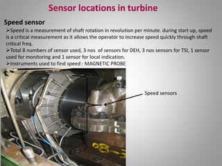
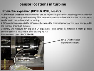
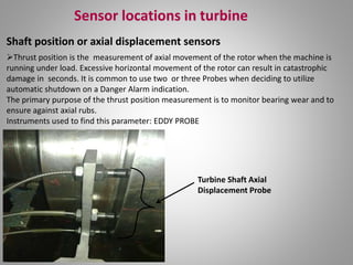
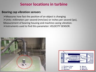
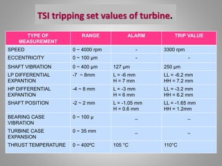
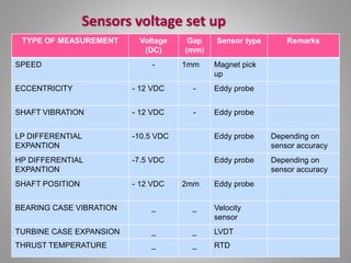
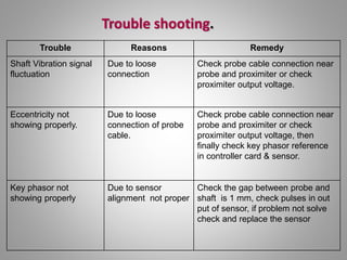
Presentation on TSI
Presented By
Narendra S. Samarth
Contents
1) Introduction
2) Measuring parameter
3) Control panel overview
4) Panel connection diagram
5) Description of card
6) Sensor location in turbine and use of sensor
7) TSI tripping set value of turbine
8) Troubleshooting
Introduction and Importance
 TSI refers to instrumentation systems that specifically perform
measurements of critical control parameters on large steam turbine
generator trains.
 TSI systems provide continuous online monitoring and machine protection
for steam generator sets.
 TSI measures a variety of supervisory parameters to provide operation
reliable machine condition information and alert them to any machinery
problems.
 To keep machine healthy and generating power continuously without
interrupting .
Turbine Supervisory Instrumentation Benefits:
The use of, and experience with, TSI assists in reducing operating costs of the generation
units by:
Reducing Turbine Roll Time:
During turbine run up or coast down of large turbines, there are extensive soak periods
to ensure stationary and rotating parts thermally expand equally. These periods are
usually of a conservative length, but times can be further reduced with continuous and
accurate measurement of key expansion clearances (and related parameters)available
with TSI systems
Benefits of TSI.
TSI SCADA view
Outlook Picture of the Turbine
Control panel over view.
Panel connection diagram.
CARD MODEL NO. DISCRIPTION
MMS 6312 SPEED
MMS 6220 ECCENTRYCITY
MMS 6120 BEARING VIBRATION
MMS 6210 DIFFERENTIAL EXPANTION AND
SHAFT POSITION
MMS 6110 SHAFT VIBRATION
MMS 6823 CU
Description of cards.
Description of cards
Speed control card OS1 &TM (MMS 6312)
Description of cards.
Speed control card OS2 & Key phasor (MMS 6312)
Description of cards.
Speed control card OS3 (MMS 6312)
Description of cards.
Eccentricity control card (MMS 6220)
Description of cards.
Bearing Vibration control card (MMS 6120)
Description of cards.
Shaft Position (axial shift) control card SP1,2&3 (MMS 6210)
Description of cards.
Differential Expansion HPDE & LPDE (MMS 6210)
Description of cards.
Shaft Vibration control card (MMS 6110)
Description of cards.
Communication card (MMS 6823)
Description of cards
LED STATUS
ALARM LED
CONFIGURATION
INTERFACE
RS 232
Mini Coax
sockets for
sensor signal
(raw signal of
converter)
Measuring parameter
• TSI system measurements can be broken down
into four major categories
 Motion Measurement.
 Position Measurement.
 Speed Measurement.
 Process Measurement.
Motion measurements.
This include vibration on main turbine generator ,exciter ,bearing etc .so ,all shaft and
bearing vibrations comes under this category
Instruments used to measure vibration:
Eddy current probes (proximity).
Velocity(seismic) sensors.
Accelerometers.
Working of eddy current probe:
Its works on the principle of eddy
current.
An alternating current flowing through the
coil produces a primary magnetic field
that induces eddy currents in the part.
Energy is needed to generate the eddy
currents.
Eddy currents flow within closed loops in
the part(within the magnetic field).
Position measurements:
• Thrust bearing wear ,rotor position , casing(shell) expansion ,
differential expansion.
• Instruments used to measure vibration:
 Eddy current probe.
 LVDT’S.
 linear/rotary potentiometers
SPEED MEASUREMENTS:
• Monitoring main turbine speed and
acceleration , over speed detection etc.
• Instruments used to measure speed:
 Passive electromagnetic.
 Eddy probes etc
Process Measurement
• Bearing white metal temperature , shell
differential temp , lube oil temperature
• Instruments used to measure vibration:
 Thermocouple.
 RTD.
Combinely TSI can measure below this parameter
• Key Phasor.
• Eccentricity.
• Shaft position/ axial displacement.
• Shaft vibration.
• Bearing Vibration.
• Bearing metal temperature.
• Thrust Pad temperature
• Differential expansion
• Case (shell) expansion.
• Speed ( Zero speed, Rotor acceleration, Over speed, Phase
angle).
Sensor locations in turbine
• Key phasor sensor
• Key phasor sensor is installed in front pedestal of the turbine
 Phase or phase angle, is a measure of the relationship of how one vibration signal
relates to another vibration signal and is commonly used to calculate the placement of a
balance weight. This parameter is not usually displayed continuously but is monitored
periodically to determine changes in the rotor balance condition, deviations in system
stiffness such as a cracked shaft
 Accurate , consistent information is essential for proper machinery and diagnostics
.consistent phase information , before and after outages is necessary to evaluate the
efficiency of the machine
 To get the correct data of the system proper installation is required
 Instrument fixed: MAGNETIC PROBE
 Radial Vibration is usually the heart of the TSI system
 This measures the dynamic motion (radial vibration) of the rotor shaft relative to the
bearing housing. This parameter will detect common machinery problems such as rubs,
imbalance, bearing stability, etc
 A complete vibration system would install two probes per bearing, with the sensors
located 90° from each other (X and Y).
Instruments used to find vibration: EDDY PROBES
Sensor locations in turbine
Shaft Vibration sensors
Shaft Vibration Y Axis
Shaft Vibration X Axis
Sensor locations in turbine
Eccentricity sensor
shaft
Eccentricity is a measurement of the amount of sag or bow in a rotor . it will
provide indication of bent shaft.
It may be caused by any or a combination of a fixed mechanical bow,
misalignment, temporary thermal bow, or a gravity bow.
This measurement is used by the operator to indicate when the machine can safely
be brought up to the speed without causing rubs or damages to the seals.
Instruments used to find eccentricity: EDDY PROBES
Eccentricity probe
Sensor locations in turbine
Speed sensor
Speed is a measurement of shaft rotation in revolution per minute. during start up, speed
is a critical measurement as it allows the operator to increase speed quickly through shaft
critical freq.
Total 8 numbers of sensor used, 3 nos of sensors for DEH, 3 nos sensors for TSI, 1 sensor
used for monitoring and 1 sensor for local indication.
Instruments used to find speed : MAGNETIC PROBE
Speed sensors
Sensor locations in turbine
Differential expansion (HPDE & LPDE) sensors
Differential Expansion measurements are an important parameter receiving much attention
during turbine startup and warming. This parameter measures how the turbine rotor expands
in relation to the turbine shell, or casing.
Differential expansion is the difference between the thermal growth of the rotor compared to
the thermal growth of the case
Generally we measure HP exp and LP expansion, one sensor is installed in front pedestal
another sensor is installed in after bearing no – 3.
Instruments used : EDDY PROBES
HP & LP differential
expansion sensors
Sensor locations in turbine
Shaft position or axial displacement sensors
Thrust position is the measurement of axial movement of the rotor when the machine is
running under load. Excessive horizontal movement of the rotor can result in catastrophic
damage in seconds. It is common to use two or three Probes when deciding to utilize
automatic shutdown on a Danger Alarm indication.
The primary purpose of the thrust position measurement is to monitor bearing wear and to
ensure against axial rubs.
Instruments used to find this parameter: EDDY PROBE
Turbine Shaft Axial
Displacement Probe
Sensor locations in turbine
Bearing cap vibration sensors
Measures how fast the position of an object is changing
Units: millimeters per second (mm/sec) or inches per second (ips),
Measurement of bearing housing and machine casing vibration.
Instruments used to find this parameter: VELOCITY SENSOR.
TSI tripping set values of turbine.
TYPE OF
MEASUREMENT
RANGE ALARM TRIP VALUE
SPEED 0 ~ 4000 rpm - 3300 rpm
ECCENTRICITY 0 ~ 100 µm - -
SHAFT VIBRATION 0 ~ 400 µm 127 µm 250 µm
LP DIFFERENTIAL
EXPANTION
-7 ~ 8mm L = -6 mm
H = 7 mm
LL = -6.2 mm
HH = 7.2 mm
HP DIFFERENTIAL
EXPANTION
-4 ~ 8 mm L = -3 mm
H = 6 mm
LL = -3.2 mm
HH = 6.2 mm
SHAFT POSITION -2 ~ 2 mm L = -1.05 mm
H = 0.6 mm
LL = -1.65 mm
HH = 1.2mm
BEARING CASE
VIBRATION
0 ~ 100 µ _ _
TURBINE CASE
EXPANSION
0 ~ 35 mm _ _
THRUST TEMPERATURE 0 ~ 400ºC 105 °C 110°C
Sensors voltage set up
TYPE OF MEASUREMENT Voltage
(DC)
Gap
(mm)
Sensor type Remarks
SPEED - 1mm Magnet pick
up
ECCENTRICITY - 12 VDC - Eddy probe
SHAFT VIBRATION - 12 VDC - Eddy probe
LP DIFFERENTIAL
EXPANTION
-10.5 VDC Eddy probe Depending on
sensor accuracy
HP DIFFERENTIAL
EXPANTION
-7.5 VDC Eddy probe Depending on
sensor accuracy
SHAFT POSITION - 12 VDC 2mm Eddy probe
BEARING CASE VIBRATION _ _ Velocity
sensor
TURBINE CASE EXPANSION _ _ LVDT
THRUST TEMPERATURE _ _ RTD
Trouble Reasons Remedy
Shaft Vibration signal
fluctuation
Due to loose
connection
Check probe cable connection near
probe and proximiter or check
proximiter output voltage.
Eccentricity not
showing properly.
Due to loose
connection of probe
cable.
Check probe cable connection near
probe and proximiter or check
proximiter output voltage, then
finally check key phasor reference
in controller card & sensor.
Key phasor not
showing properly
Due to sensor
alignment not proper
Check the gap between probe and
shaft is 1 mm, check pulses in out
put of sensor, if problem not solve
check and replace the sensor
Trouble shooting.
Trouble shooting.
Previews while turbine trip on shaft vibration unable to fined which shaft vibration was acted,
in TSI panel shaft vibration cards high outputs are made parallel finely one output was going to
the ETS, so that made modification in TSI panel each shaft vibration high signal taken
separately, for easy finding of tripping, and configuration done on DCS SCADA TSI page.
DCS SCADA TSI page TSI panel new modfication
• Thank you

(04052013) presentation on TSI.pptx

  • 1.
    Presentation on TSI PresentedBy Narendra S. Samarth
  • 2.
    Contents 1) Introduction 2) Measuringparameter 3) Control panel overview 4) Panel connection diagram 5) Description of card 6) Sensor location in turbine and use of sensor 7) TSI tripping set value of turbine 8) Troubleshooting
  • 3.
    Introduction and Importance TSI refers to instrumentation systems that specifically perform measurements of critical control parameters on large steam turbine generator trains.  TSI systems provide continuous online monitoring and machine protection for steam generator sets.  TSI measures a variety of supervisory parameters to provide operation reliable machine condition information and alert them to any machinery problems.  To keep machine healthy and generating power continuously without interrupting .
  • 4.
    Turbine Supervisory InstrumentationBenefits: The use of, and experience with, TSI assists in reducing operating costs of the generation units by: Reducing Turbine Roll Time: During turbine run up or coast down of large turbines, there are extensive soak periods to ensure stationary and rotating parts thermally expand equally. These periods are usually of a conservative length, but times can be further reduced with continuous and accurate measurement of key expansion clearances (and related parameters)available with TSI systems Benefits of TSI.
  • 5.
  • 6.
    Outlook Picture ofthe Turbine
  • 7.
  • 8.
  • 9.
  • 10.
    CARD MODEL NO.DISCRIPTION MMS 6312 SPEED MMS 6220 ECCENTRYCITY MMS 6120 BEARING VIBRATION MMS 6210 DIFFERENTIAL EXPANTION AND SHAFT POSITION MMS 6110 SHAFT VIBRATION MMS 6823 CU Description of cards.
  • 11.
    Description of cards Speedcontrol card OS1 &TM (MMS 6312)
  • 12.
    Description of cards. Speedcontrol card OS2 & Key phasor (MMS 6312)
  • 13.
    Description of cards. Speedcontrol card OS3 (MMS 6312)
  • 14.
    Description of cards. Eccentricitycontrol card (MMS 6220)
  • 15.
    Description of cards. BearingVibration control card (MMS 6120)
  • 16.
    Description of cards. ShaftPosition (axial shift) control card SP1,2&3 (MMS 6210)
  • 17.
    Description of cards. DifferentialExpansion HPDE & LPDE (MMS 6210)
  • 18.
    Description of cards. ShaftVibration control card (MMS 6110)
  • 19.
  • 20.
    Description of cards LEDSTATUS ALARM LED CONFIGURATION INTERFACE RS 232 Mini Coax sockets for sensor signal (raw signal of converter)
  • 21.
    Measuring parameter • TSIsystem measurements can be broken down into four major categories  Motion Measurement.  Position Measurement.  Speed Measurement.  Process Measurement.
  • 22.
    Motion measurements. This includevibration on main turbine generator ,exciter ,bearing etc .so ,all shaft and bearing vibrations comes under this category Instruments used to measure vibration: Eddy current probes (proximity). Velocity(seismic) sensors. Accelerometers. Working of eddy current probe: Its works on the principle of eddy current. An alternating current flowing through the coil produces a primary magnetic field that induces eddy currents in the part. Energy is needed to generate the eddy currents. Eddy currents flow within closed loops in the part(within the magnetic field).
  • 23.
    Position measurements: • Thrustbearing wear ,rotor position , casing(shell) expansion , differential expansion. • Instruments used to measure vibration:  Eddy current probe.  LVDT’S.  linear/rotary potentiometers
  • 24.
    SPEED MEASUREMENTS: • Monitoringmain turbine speed and acceleration , over speed detection etc. • Instruments used to measure speed:  Passive electromagnetic.  Eddy probes etc
  • 25.
    Process Measurement • Bearingwhite metal temperature , shell differential temp , lube oil temperature • Instruments used to measure vibration:  Thermocouple.  RTD.
  • 26.
    Combinely TSI canmeasure below this parameter • Key Phasor. • Eccentricity. • Shaft position/ axial displacement. • Shaft vibration. • Bearing Vibration. • Bearing metal temperature. • Thrust Pad temperature • Differential expansion • Case (shell) expansion. • Speed ( Zero speed, Rotor acceleration, Over speed, Phase angle).
  • 27.
    Sensor locations inturbine • Key phasor sensor • Key phasor sensor is installed in front pedestal of the turbine  Phase or phase angle, is a measure of the relationship of how one vibration signal relates to another vibration signal and is commonly used to calculate the placement of a balance weight. This parameter is not usually displayed continuously but is monitored periodically to determine changes in the rotor balance condition, deviations in system stiffness such as a cracked shaft  Accurate , consistent information is essential for proper machinery and diagnostics .consistent phase information , before and after outages is necessary to evaluate the efficiency of the machine  To get the correct data of the system proper installation is required  Instrument fixed: MAGNETIC PROBE
  • 28.
     Radial Vibrationis usually the heart of the TSI system  This measures the dynamic motion (radial vibration) of the rotor shaft relative to the bearing housing. This parameter will detect common machinery problems such as rubs, imbalance, bearing stability, etc  A complete vibration system would install two probes per bearing, with the sensors located 90° from each other (X and Y). Instruments used to find vibration: EDDY PROBES Sensor locations in turbine Shaft Vibration sensors Shaft Vibration Y Axis Shaft Vibration X Axis
  • 29.
    Sensor locations inturbine Eccentricity sensor shaft Eccentricity is a measurement of the amount of sag or bow in a rotor . it will provide indication of bent shaft. It may be caused by any or a combination of a fixed mechanical bow, misalignment, temporary thermal bow, or a gravity bow. This measurement is used by the operator to indicate when the machine can safely be brought up to the speed without causing rubs or damages to the seals. Instruments used to find eccentricity: EDDY PROBES Eccentricity probe
  • 30.
    Sensor locations inturbine Speed sensor Speed is a measurement of shaft rotation in revolution per minute. during start up, speed is a critical measurement as it allows the operator to increase speed quickly through shaft critical freq. Total 8 numbers of sensor used, 3 nos of sensors for DEH, 3 nos sensors for TSI, 1 sensor used for monitoring and 1 sensor for local indication. Instruments used to find speed : MAGNETIC PROBE Speed sensors
  • 31.
    Sensor locations inturbine Differential expansion (HPDE & LPDE) sensors Differential Expansion measurements are an important parameter receiving much attention during turbine startup and warming. This parameter measures how the turbine rotor expands in relation to the turbine shell, or casing. Differential expansion is the difference between the thermal growth of the rotor compared to the thermal growth of the case Generally we measure HP exp and LP expansion, one sensor is installed in front pedestal another sensor is installed in after bearing no – 3. Instruments used : EDDY PROBES HP & LP differential expansion sensors
  • 32.
    Sensor locations inturbine Shaft position or axial displacement sensors Thrust position is the measurement of axial movement of the rotor when the machine is running under load. Excessive horizontal movement of the rotor can result in catastrophic damage in seconds. It is common to use two or three Probes when deciding to utilize automatic shutdown on a Danger Alarm indication. The primary purpose of the thrust position measurement is to monitor bearing wear and to ensure against axial rubs. Instruments used to find this parameter: EDDY PROBE Turbine Shaft Axial Displacement Probe
  • 33.
    Sensor locations inturbine Bearing cap vibration sensors Measures how fast the position of an object is changing Units: millimeters per second (mm/sec) or inches per second (ips), Measurement of bearing housing and machine casing vibration. Instruments used to find this parameter: VELOCITY SENSOR.
  • 34.
    TSI tripping setvalues of turbine. TYPE OF MEASUREMENT RANGE ALARM TRIP VALUE SPEED 0 ~ 4000 rpm - 3300 rpm ECCENTRICITY 0 ~ 100 µm - - SHAFT VIBRATION 0 ~ 400 µm 127 µm 250 µm LP DIFFERENTIAL EXPANTION -7 ~ 8mm L = -6 mm H = 7 mm LL = -6.2 mm HH = 7.2 mm HP DIFFERENTIAL EXPANTION -4 ~ 8 mm L = -3 mm H = 6 mm LL = -3.2 mm HH = 6.2 mm SHAFT POSITION -2 ~ 2 mm L = -1.05 mm H = 0.6 mm LL = -1.65 mm HH = 1.2mm BEARING CASE VIBRATION 0 ~ 100 µ _ _ TURBINE CASE EXPANSION 0 ~ 35 mm _ _ THRUST TEMPERATURE 0 ~ 400ºC 105 °C 110°C
  • 35.
    Sensors voltage setup TYPE OF MEASUREMENT Voltage (DC) Gap (mm) Sensor type Remarks SPEED - 1mm Magnet pick up ECCENTRICITY - 12 VDC - Eddy probe SHAFT VIBRATION - 12 VDC - Eddy probe LP DIFFERENTIAL EXPANTION -10.5 VDC Eddy probe Depending on sensor accuracy HP DIFFERENTIAL EXPANTION -7.5 VDC Eddy probe Depending on sensor accuracy SHAFT POSITION - 12 VDC 2mm Eddy probe BEARING CASE VIBRATION _ _ Velocity sensor TURBINE CASE EXPANSION _ _ LVDT THRUST TEMPERATURE _ _ RTD
  • 36.
    Trouble Reasons Remedy ShaftVibration signal fluctuation Due to loose connection Check probe cable connection near probe and proximiter or check proximiter output voltage. Eccentricity not showing properly. Due to loose connection of probe cable. Check probe cable connection near probe and proximiter or check proximiter output voltage, then finally check key phasor reference in controller card & sensor. Key phasor not showing properly Due to sensor alignment not proper Check the gap between probe and shaft is 1 mm, check pulses in out put of sensor, if problem not solve check and replace the sensor Trouble shooting.
  • 37.
    Trouble shooting. Previews whileturbine trip on shaft vibration unable to fined which shaft vibration was acted, in TSI panel shaft vibration cards high outputs are made parallel finely one output was going to the ETS, so that made modification in TSI panel each shaft vibration high signal taken separately, for easy finding of tripping, and configuration done on DCS SCADA TSI page. DCS SCADA TSI page TSI panel new modfication
  • 38.