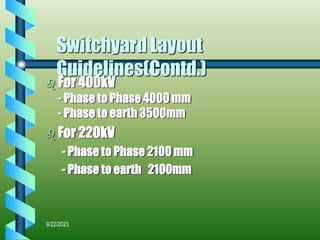
EHV Transmission Equipments
9/22/2023
Over view
 Switching Schemes.
 Line Towers.
 Type of conductors.
 Switchyard types.
 Switchyard equipments.
 Switchyard Layouts.
9/22/2023
Switching schemes
 Single bus.
 Main and Transfer (sectionalised).
 Double bus.
 One and half breaker scheme.
 Double main and Transfer
(Sectionalised).
9/22/2023
Factors Affecting Switching
Scheme
 System Security/Reliability.
- Feeder Fault.
- Bus Fault.
- Equipment Failure.
- Redundancy.
9/22/2023
Factors Affecting Switching
Scheme (Contd.)
 Operational Flexibility.
 Ease of Maintenance.
 Simplicity of Protection Arrangements.
 Ease of Extension.
 Area available.
 Cost.
9/22/2023
Line Towers
 Single Circuit.
 Double Circuit.
 Dead end type.
 Tension Towers.
 Suspension Towers.
9/22/2023
Tower Design
 Wind Force.
 Conductor Tension.
 Span.
 Type of conductor.
9/22/2023
Tower Hardwares
 Insulator Strings.
 Vibration Dampers.
 Spacers.
 Earthwire & OPGW.
9/22/2023
Type of Conductor
 ACSR Moose (800A).
 Zebra (700A).
 Rabbit (190A).
 Dog (290A).
9/22/2023
Switchyard Type
 Conventional Air Insulated Type.
 Gas Insulated type.
 Air Insulated (Enclosed type).
9/22/2023
Switchyard Equipments.
 Circuit Breaker.
 Disconnectors.
 Current Transformers.
 Capacitor Voltage Transformers.
 Lightning Arrestors.
 Post Insulators.
 Wave Traps
9/22/2023
General Parameters
 Dielectric Parameters .(IEC 694)
- Power Frequency Voltage.
- Lightning Impulse Voltage.
- Switching Impulse Voltage.
- Corona Extinction Voltage.
- RIV Level.
9/22/2023
400kV Equipments
a. Rated voltage 420 kV
b. Rated frequency 50 Hz
c. Rated short time withstand
current capacity
40 kA rms for one (1) second
d. Insulation levels for 420kV Circuit
breakers and Disconnecting
Switches
e. i) Rated one minute power
Frequency withstand voltage
a) 520 kV rms between live
terminals and earth.
b) 610 kV rms across isolating
distance.
ii) Rated lightning impulse
withstand voltage
a) +/- 1425 kVp between live terminals
and earth.
b) +/- 1425 kVp impulse on one
terminal and 240 kVp power
frequency of opposite polarity on
other terminal (across isolating
distance).
iii) Rated switching impulse
withstand voltage
a) +/- 1050 kVp between live
terminals and earth.
b) +/- 900 kVp impulse on one
terminal and 345 kVp power
frequency of opposite polarity on
other terminal (across isolating
distance).
f. Max. Radio interference voltage
at 266kVrms
1000 micro volts for frequency
between 0.5 Mhz and 2.0 Mhz for all
equipment. However, for insulator
strings the measurement would be
at 305 kV .
g. Corona extinction voltage Not less than 320 kV rms
9/22/2023
220kV Equipments
a. Rated voltage 245 kV
b. Rated frequency 50 Hz
c. Rated short time withstand
current capacity
40 kA rms for one (1) second
d. Insulation levels for 245kV Circuit
breakers and Disconnecting
Switches
e. i) Rated one minute power
Frequency withstand voltage
a) 460 kV rms between live
terminals and earth.
b) 460 kV rms across isolating
distance.
ii) Rated lightning impulse
withstand voltage
a) +/- 1050 kVp between live
terminals and earth.
b) +/- 1050 kVp impulse on one
terminal and other terminal
earthed (across isolating
distance).
f. Max. Radio interference voltage
at 156kVrms
1000 micro volts for frequency
between 0.5 Mhz and 2.0 Mhz for all
equipment.
9/22/2023
132kV Equipments
a. Rated voltage 145 kV
b. Rated frequency 50 Hz
c. Rated short time withstand
current capacity
31.5 kA rms for one (1) second
d. Insulation levels for 145kV Circuit
breakers and Disconnecting
Switches
e. i) Rated one minute power
Frequency withstand voltage
a) 275 kV rms between live
terminals and earth.
b) 275 kV rms across isolating
distance.
ii) Rated lightning impulse
withstand voltage
a) +/- 460 kVp between live
terminals and earth.
b) +/- 460 kVp impulse on one
terminal and other terminal
earthed (across isolating
distance).
f. Max. Radio interference voltage
at 92kVrms
1000 micro volts for frequency
between 0.5 Mhz and 2.0 Mhz for all
equipment.
9/22/2023
General Parameters (Contd.)
 Rated Current.
 Short Time Current.
 Creepage Distance.
9/22/2023
Circuit Breakers Type
 MOCB.
 ABCB.
 SF6
9/22/2023
Circuit Breaker
 Fault clearing.
 Load Make Break.
 Break Time.
 Single/Multi Break.
 Voltage Distribution across breaks.
 Closing resistors.
 Operating mechanism
(Spring/Pneumatic/Hydraulic)
9/22/2023
Disconnectors
 HCB Type.
 Double Break Type.
 Pantograph type.
 Vertical Break type.
 Provision of Earth Switches.
 Motor / Pneumatic operated.
 Gang operated/Single pole type.
9/22/2023
Current Transformer
 Dead tank/Live tank type.
 Bar Primary type.
 Ring Type.
 No. of Cores.
 Ratio.
 Accuracy.
9/22/2023
Capacitor Voltage Transformer
 Capacitance.
 Voltage Ratio.
 No. Of Cores.
 Accuracy.
9/22/2023
Lightning Arrestor
 Gap Type / Gapless Type.
 Voltage Rating.
 Energy Capability.
 Monitoring.
 Location.
9/22/2023
Post Insulators
 Voltage Rating.
 Cantilever Strength.
 Fixing Details.
9/22/2023
Wave Trap
 Rated Inductance(0.5/1.0 mH).
 Rated current.
 Band Width.
 Coupling (Phase to Phase).
9/22/2023
Switchyard Layout Guidelines
 Place All Equpt. At ground level for ease of
maintenance.
 Busbars placed at right angles to feeders.
 Accessibility of feeders from either side of
switchyard.
 Conductor crossings at right angles be
separated to achieve adequate clearances.
9/22/2023
Switchyard Layout
Guidelines(Contd.)
 For 400kV
- Phase to Phase 4000 mm
- Phase to earth 3500mm
 For 220kV
- Phase to Phase 2100 mm
- Phase to earth 2100mm
9/22/2023
Switchyard Layout
Guidelines(Contd.)
 Lower level connections can be of Rigid pipe or
flexible conductor.
 Upper level connections can be of strung type
only.
 For aesthetic looks and similarity all same
equipments be in one line as far as possible.
 Road near circuit breaker be kept for
maintenance purpose.
9/22/2023
Switchyard Layout
Guidelines(Contd.)
 Provide Double insulator strings for upper level
for safety reasons and to avoid busfaults due to
conductor snapping.
 Cable trenches to be routed for ease in
maintenance and movement.
 Lightning protection to be provided using
Lightning masts and/or shield wires.
 Lighting to be provided by fixtures on LM platform.
THANK YOU

Switchyard.ppt

  • 1.
  • 2.
    9/22/2023 Over view  SwitchingSchemes.  Line Towers.  Type of conductors.  Switchyard types.  Switchyard equipments.  Switchyard Layouts.
  • 3.
    9/22/2023 Switching schemes  Singlebus.  Main and Transfer (sectionalised).  Double bus.  One and half breaker scheme.  Double main and Transfer (Sectionalised).
  • 4.
    9/22/2023 Factors Affecting Switching Scheme System Security/Reliability. - Feeder Fault. - Bus Fault. - Equipment Failure. - Redundancy.
  • 5.
    9/22/2023 Factors Affecting Switching Scheme(Contd.)  Operational Flexibility.  Ease of Maintenance.  Simplicity of Protection Arrangements.  Ease of Extension.  Area available.  Cost.
  • 6.
    9/22/2023 Line Towers  SingleCircuit.  Double Circuit.  Dead end type.  Tension Towers.  Suspension Towers.
  • 7.
    9/22/2023 Tower Design  WindForce.  Conductor Tension.  Span.  Type of conductor.
  • 8.
    9/22/2023 Tower Hardwares  InsulatorStrings.  Vibration Dampers.  Spacers.  Earthwire & OPGW.
  • 9.
    9/22/2023 Type of Conductor ACSR Moose (800A).  Zebra (700A).  Rabbit (190A).  Dog (290A).
  • 10.
    9/22/2023 Switchyard Type  ConventionalAir Insulated Type.  Gas Insulated type.  Air Insulated (Enclosed type).
  • 11.
    9/22/2023 Switchyard Equipments.  CircuitBreaker.  Disconnectors.  Current Transformers.  Capacitor Voltage Transformers.  Lightning Arrestors.  Post Insulators.  Wave Traps
  • 12.
    9/22/2023 General Parameters  DielectricParameters .(IEC 694) - Power Frequency Voltage. - Lightning Impulse Voltage. - Switching Impulse Voltage. - Corona Extinction Voltage. - RIV Level.
  • 13.
    9/22/2023 400kV Equipments a. Ratedvoltage 420 kV b. Rated frequency 50 Hz c. Rated short time withstand current capacity 40 kA rms for one (1) second d. Insulation levels for 420kV Circuit breakers and Disconnecting Switches e. i) Rated one minute power Frequency withstand voltage a) 520 kV rms between live terminals and earth. b) 610 kV rms across isolating distance. ii) Rated lightning impulse withstand voltage a) +/- 1425 kVp between live terminals and earth. b) +/- 1425 kVp impulse on one terminal and 240 kVp power frequency of opposite polarity on other terminal (across isolating distance). iii) Rated switching impulse withstand voltage a) +/- 1050 kVp between live terminals and earth. b) +/- 900 kVp impulse on one terminal and 345 kVp power frequency of opposite polarity on other terminal (across isolating distance). f. Max. Radio interference voltage at 266kVrms 1000 micro volts for frequency between 0.5 Mhz and 2.0 Mhz for all equipment. However, for insulator strings the measurement would be at 305 kV . g. Corona extinction voltage Not less than 320 kV rms
  • 14.
    9/22/2023 220kV Equipments a. Ratedvoltage 245 kV b. Rated frequency 50 Hz c. Rated short time withstand current capacity 40 kA rms for one (1) second d. Insulation levels for 245kV Circuit breakers and Disconnecting Switches e. i) Rated one minute power Frequency withstand voltage a) 460 kV rms between live terminals and earth. b) 460 kV rms across isolating distance. ii) Rated lightning impulse withstand voltage a) +/- 1050 kVp between live terminals and earth. b) +/- 1050 kVp impulse on one terminal and other terminal earthed (across isolating distance). f. Max. Radio interference voltage at 156kVrms 1000 micro volts for frequency between 0.5 Mhz and 2.0 Mhz for all equipment.
  • 15.
    9/22/2023 132kV Equipments a. Ratedvoltage 145 kV b. Rated frequency 50 Hz c. Rated short time withstand current capacity 31.5 kA rms for one (1) second d. Insulation levels for 145kV Circuit breakers and Disconnecting Switches e. i) Rated one minute power Frequency withstand voltage a) 275 kV rms between live terminals and earth. b) 275 kV rms across isolating distance. ii) Rated lightning impulse withstand voltage a) +/- 460 kVp between live terminals and earth. b) +/- 460 kVp impulse on one terminal and other terminal earthed (across isolating distance). f. Max. Radio interference voltage at 92kVrms 1000 micro volts for frequency between 0.5 Mhz and 2.0 Mhz for all equipment.
  • 16.
    9/22/2023 General Parameters (Contd.) Rated Current.  Short Time Current.  Creepage Distance.
  • 17.
    9/22/2023 Circuit Breakers Type MOCB.  ABCB.  SF6
  • 18.
    9/22/2023 Circuit Breaker  Faultclearing.  Load Make Break.  Break Time.  Single/Multi Break.  Voltage Distribution across breaks.  Closing resistors.  Operating mechanism (Spring/Pneumatic/Hydraulic)
  • 19.
    9/22/2023 Disconnectors  HCB Type. Double Break Type.  Pantograph type.  Vertical Break type.  Provision of Earth Switches.  Motor / Pneumatic operated.  Gang operated/Single pole type.
  • 20.
    9/22/2023 Current Transformer  Deadtank/Live tank type.  Bar Primary type.  Ring Type.  No. of Cores.  Ratio.  Accuracy.
  • 21.
    9/22/2023 Capacitor Voltage Transformer Capacitance.  Voltage Ratio.  No. Of Cores.  Accuracy.
  • 22.
    9/22/2023 Lightning Arrestor  GapType / Gapless Type.  Voltage Rating.  Energy Capability.  Monitoring.  Location.
  • 23.
    9/22/2023 Post Insulators  VoltageRating.  Cantilever Strength.  Fixing Details.
  • 24.
    9/22/2023 Wave Trap  RatedInductance(0.5/1.0 mH).  Rated current.  Band Width.  Coupling (Phase to Phase).
  • 25.
    9/22/2023 Switchyard Layout Guidelines Place All Equpt. At ground level for ease of maintenance.  Busbars placed at right angles to feeders.  Accessibility of feeders from either side of switchyard.  Conductor crossings at right angles be separated to achieve adequate clearances.
  • 26.
    9/22/2023 Switchyard Layout Guidelines(Contd.)  For400kV - Phase to Phase 4000 mm - Phase to earth 3500mm  For 220kV - Phase to Phase 2100 mm - Phase to earth 2100mm
  • 27.
    9/22/2023 Switchyard Layout Guidelines(Contd.)  Lowerlevel connections can be of Rigid pipe or flexible conductor.  Upper level connections can be of strung type only.  For aesthetic looks and similarity all same equipments be in one line as far as possible.  Road near circuit breaker be kept for maintenance purpose.
  • 28.
    9/22/2023 Switchyard Layout Guidelines(Contd.)  ProvideDouble insulator strings for upper level for safety reasons and to avoid busfaults due to conductor snapping.  Cable trenches to be routed for ease in maintenance and movement.  Lightning protection to be provided using Lightning masts and/or shield wires.  Lighting to be provided by fixtures on LM platform.
  • 29.

Editor's Notes