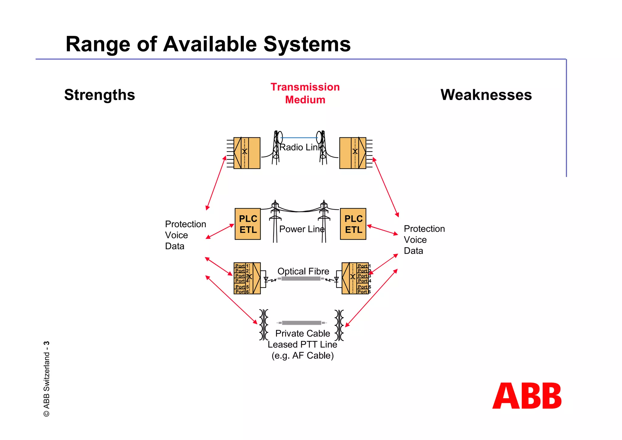
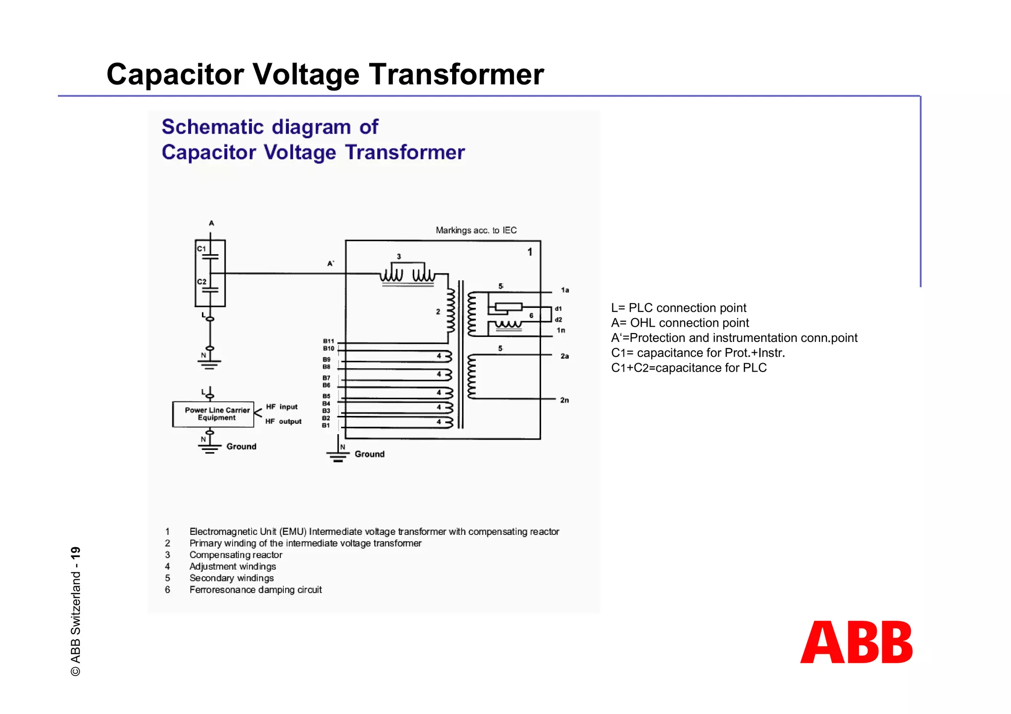
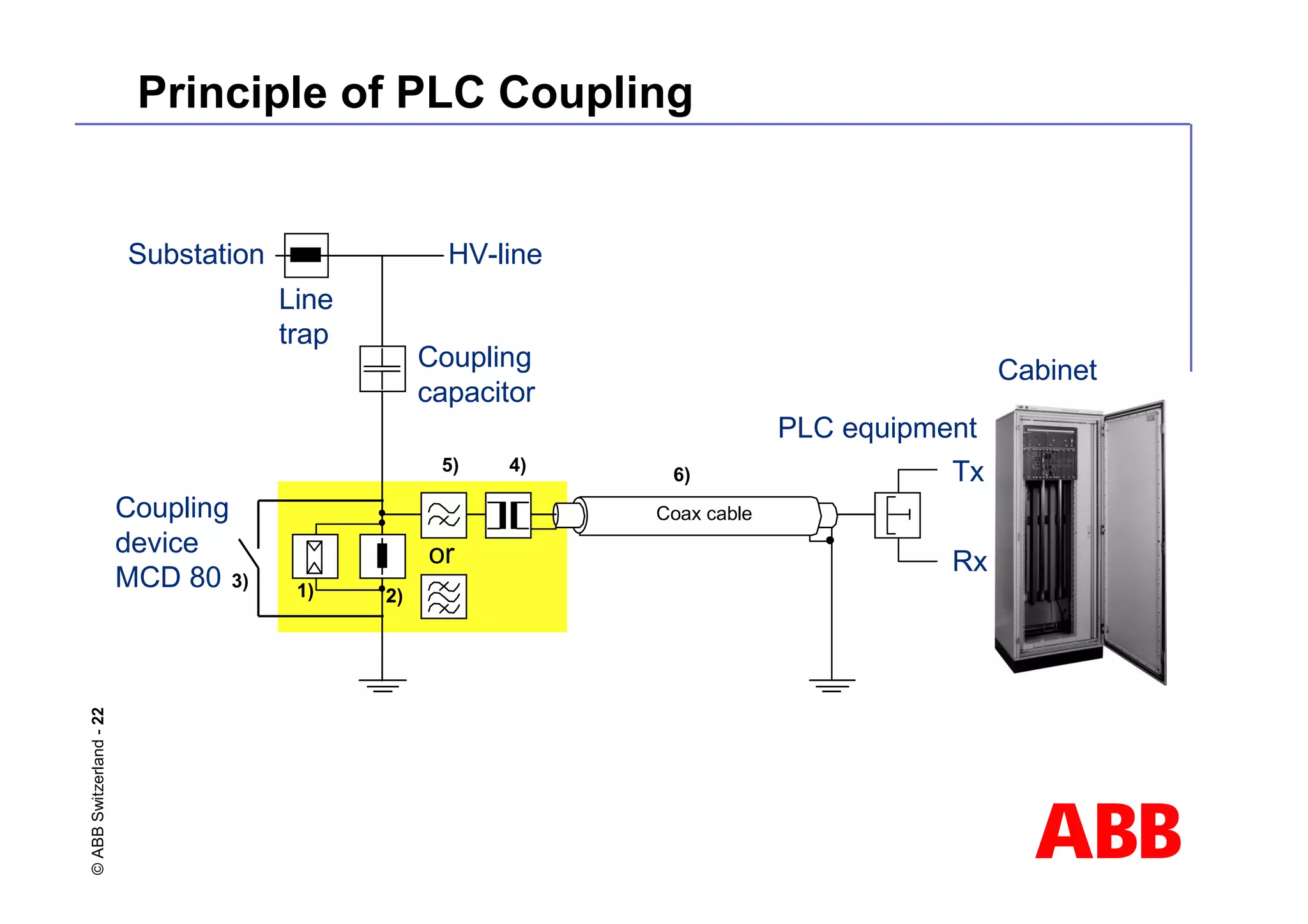
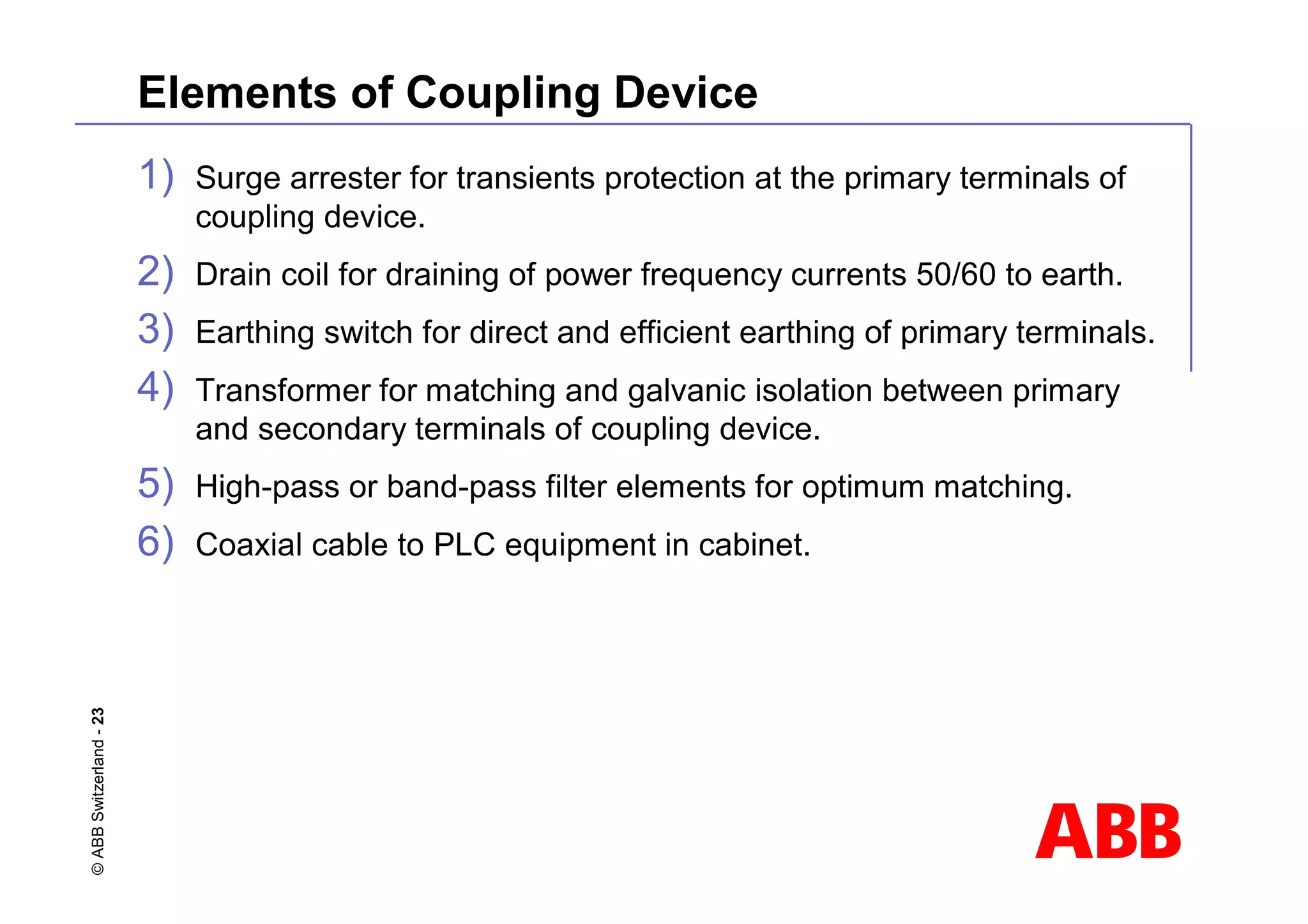
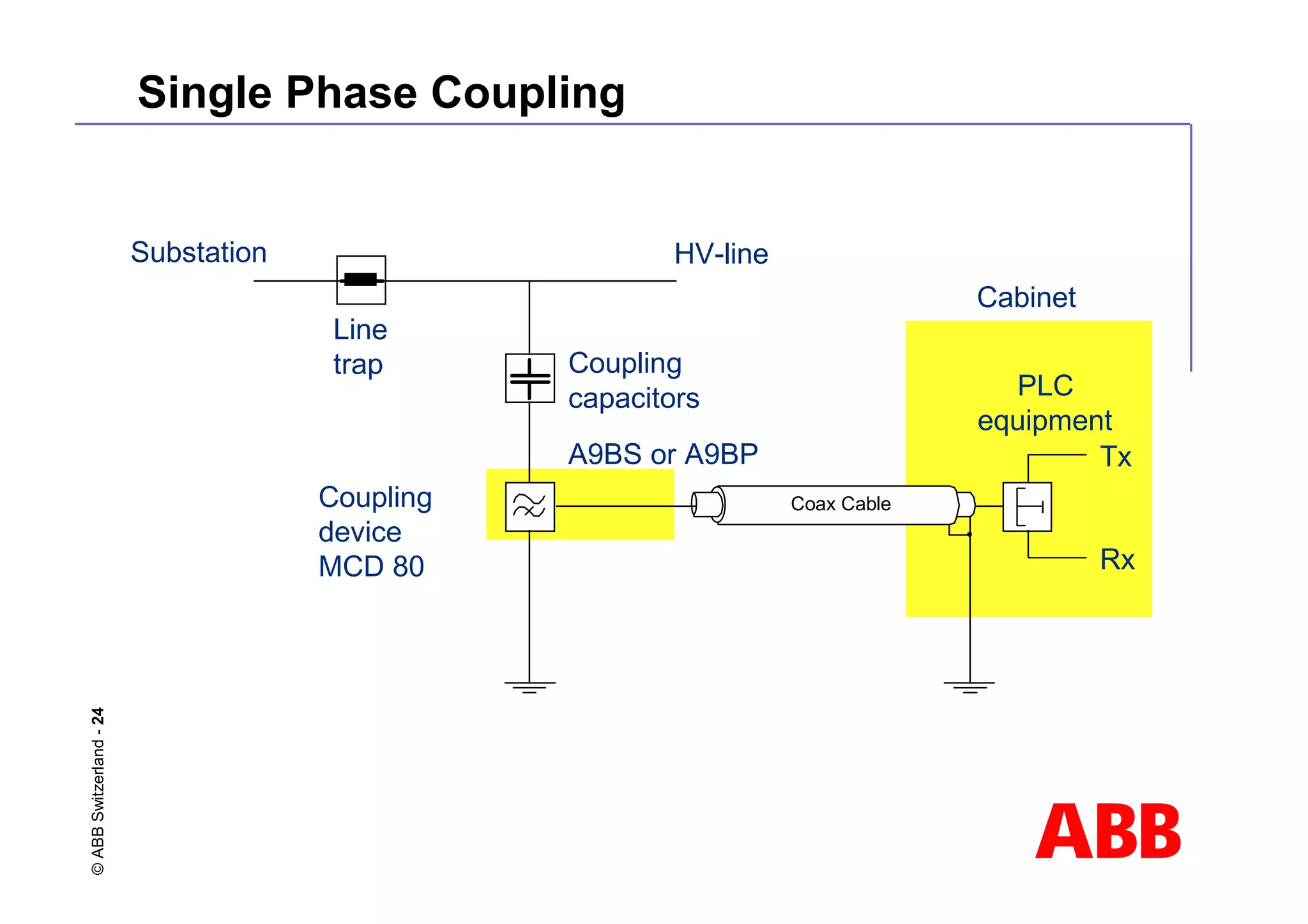
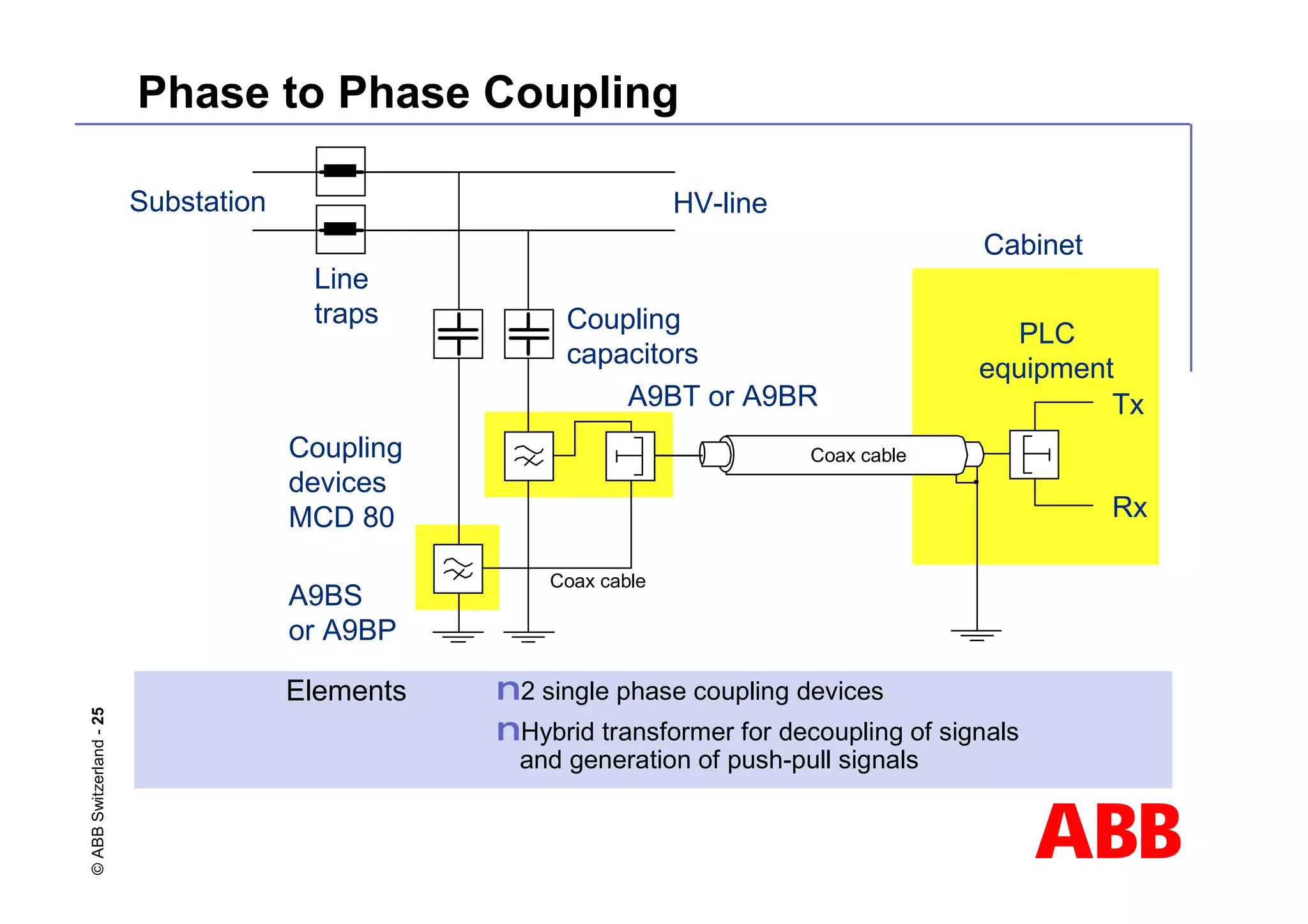
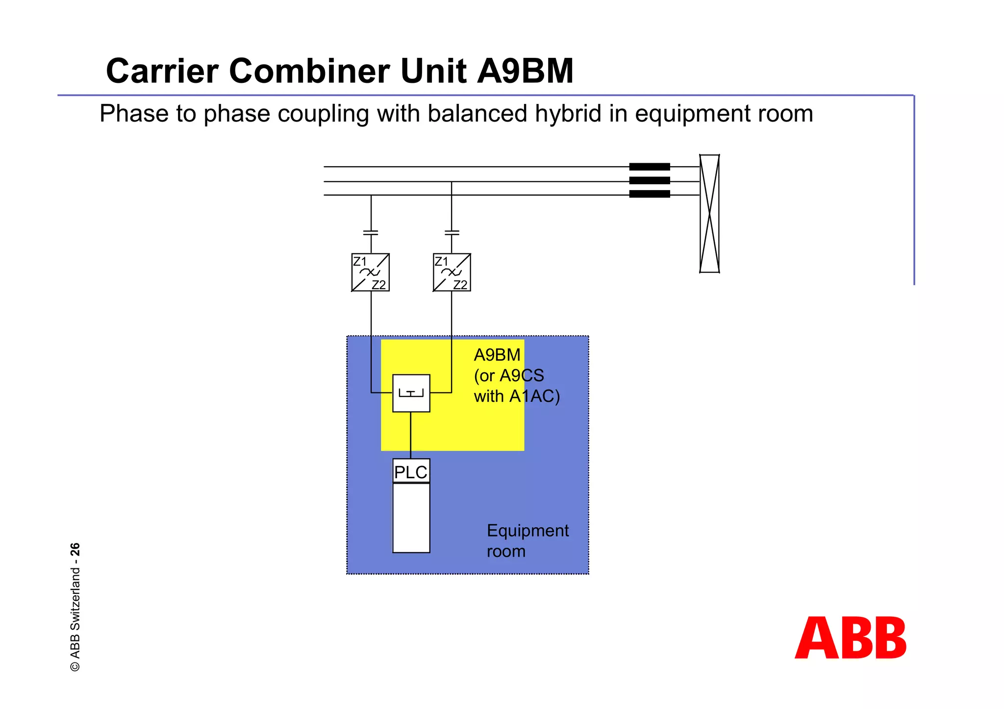
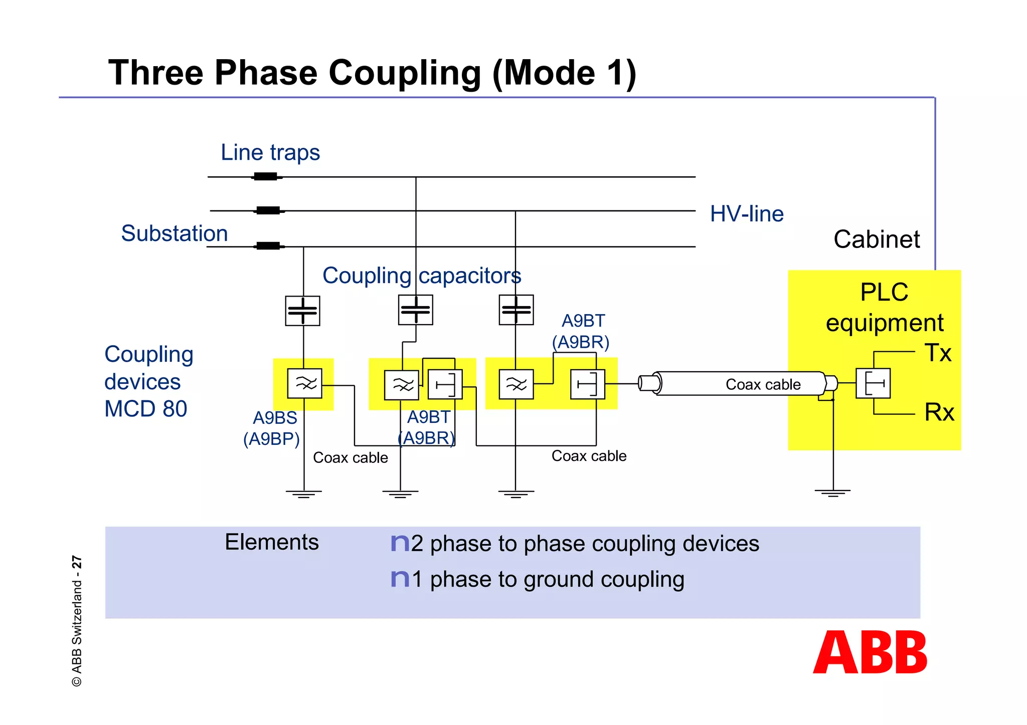
This document discusses power line carrier (PLC) systems for transmitting data and signals over power lines. It covers PLC components like line traps, coupling capacitors, and coupling devices. It describes how to choose appropriate line traps based on system parameters. It also provides details on band-pass and high-pass coupling filters used in PLC systems and their tuning characteristics. Diagrams show examples of single phase and three phase PLC coupling configurations.
![ABB
©
ABB
Switzerland
-
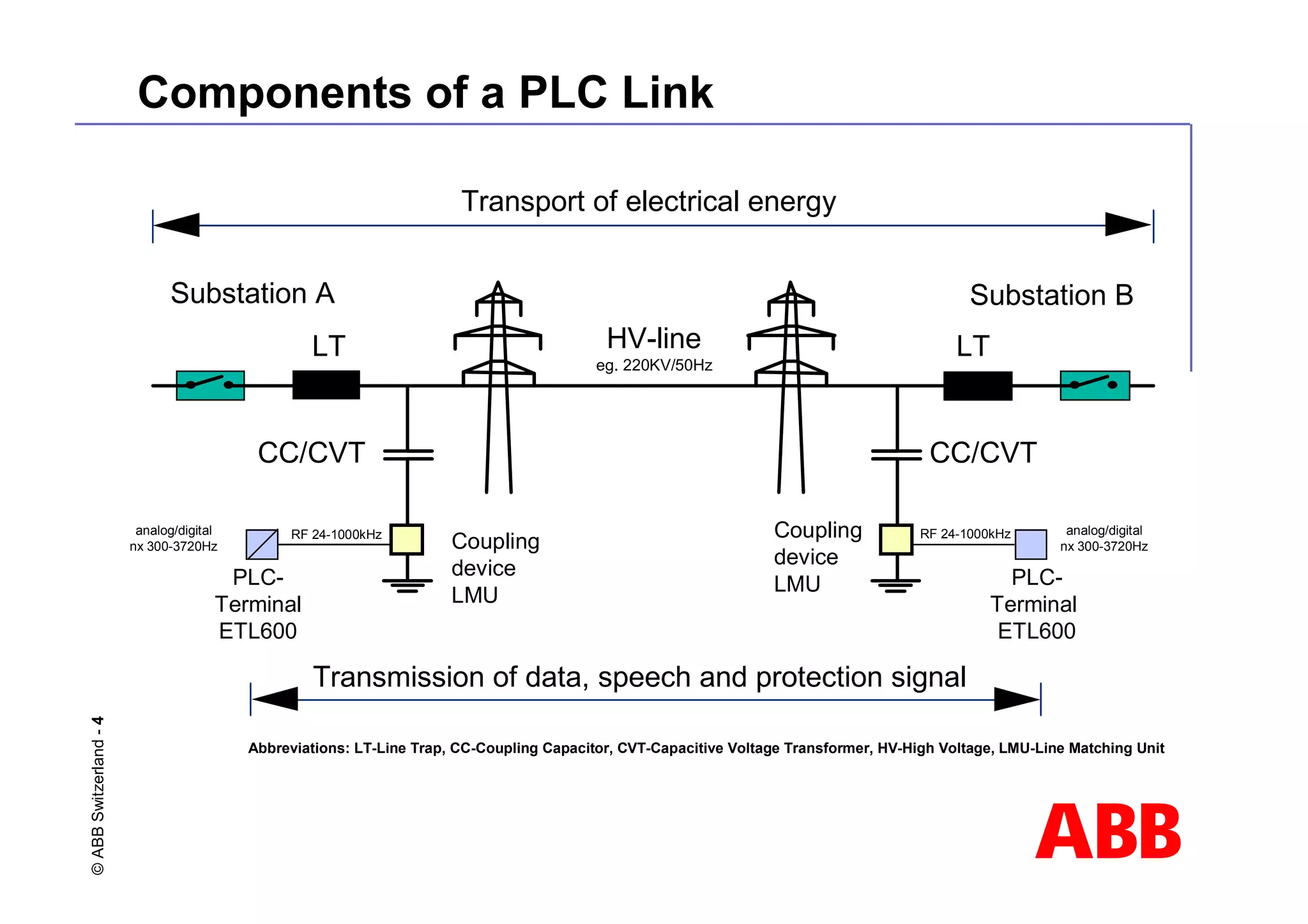
12 Impedance of Line Trap
0 50 100 150 200 250 300
1000
800
600
400
200
0
Blocking
impedance,
-resistance
Frequency [kHz]
Rated value
L1
Arrestor
L
C
R
Tuning Device
L1 = Main coil of line trap
C, L, R = Tuning device elements
Equivalent circuit diagram
7](https://image.slidesharecdn.com/02-fundamentalsofpowerlinecarrier-230206114131-5a12ce9b/75/02-Fundamentals-of-Power-Line-Carrier-pdf-12-2048.jpg)
![ABB
©
ABB
Switzerland
-
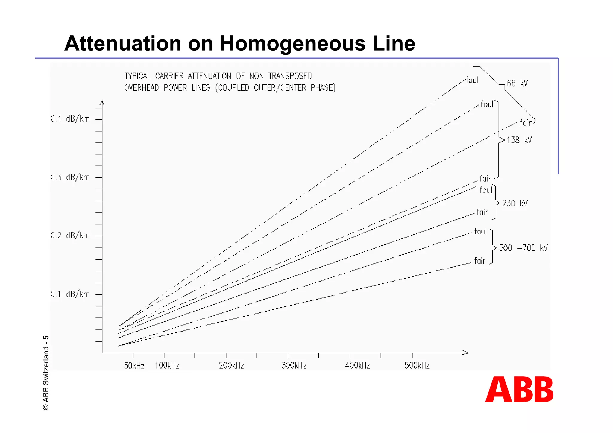
13 Band Limits
Lower band limit [kHz]
0 50 100 150 200
0
100
200
300
400
500
1.0 mH
0.5 mH 0.315 mH
2.0 mH
0.2 mH
Upper
band
limit
[kHz]
Valid for blocking
resistance Rb > 400 Ohm
Band Tuned Line Traps Type DLTC](https://image.slidesharecdn.com/02-fundamentalsofpowerlinecarrier-230206114131-5a12ce9b/75/02-Fundamentals-of-Power-Line-Carrier-pdf-13-2048.jpg)
![ABB
©
ABB
Switzerland
-
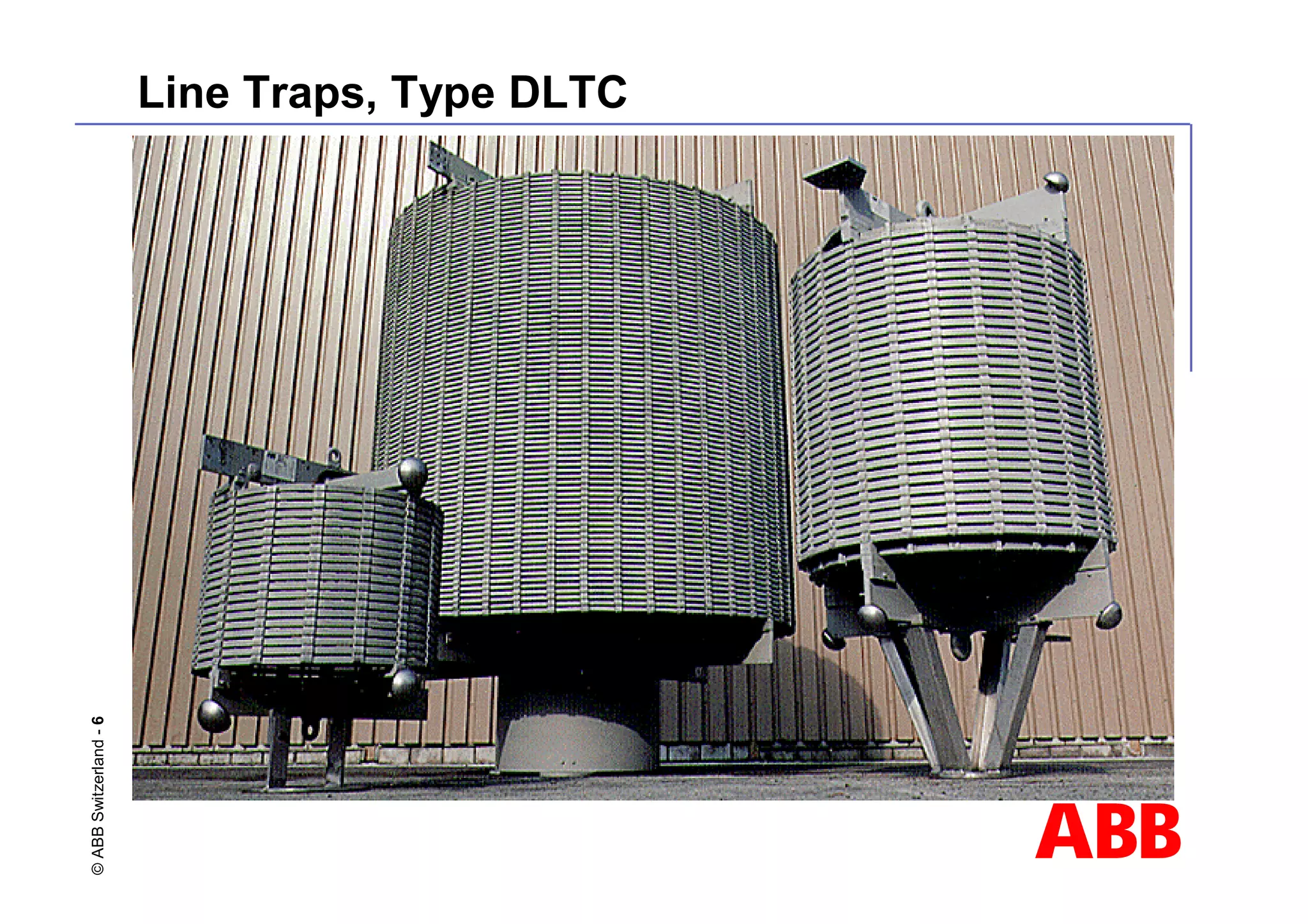
14 Band Limits
Lower band limit [kHz]
0 50 100 150 200
0
100
200
300
400
500
Upper
band
limit
[kHz]
1.0 mH
0.5 mH 0.315 mH
2.0 mH
0.2 mH
250
Band Tuned Line Traps Type DLTC
Blocking resistance Rb> 600Ohm](https://image.slidesharecdn.com/02-fundamentalsofpowerlinecarrier-230206114131-5a12ce9b/75/02-Fundamentals-of-Power-Line-Carrier-pdf-14-2048.jpg)
![ABB
©
ABB
Switzerland
-
28 High-Pass Coupling Device A9BS/A9BT
A G K L H 125ž
75ž
M N
O
1
2
3
P
Q R
B
C
C1
Z2
LE C
T
L2
L1
Z1
T1
CK
F1
D
E
F
Ck 1500 2200 2700 3300 3900 4700 5600 6800 7500
Z1 pF to to to to to to to to and
Ω 2199 2699 3299 3899 4699 5599 6799 7499 up
240 232 158 132 115 96 80 70 60 52
320 180 128 102 90 78 76 70 58 52
Lower frequency limit f1 [kHz]
Ck = coupling capacitance Upper frequency limit f2 = 500 [kHz]
Z1 = impedance of overhead line Z2 = equipment side impedance
C2
C3
C4
Z2
Q1](https://image.slidesharecdn.com/02-fundamentalsofpowerlinecarrier-230206114131-5a12ce9b/75/02-Fundamentals-of-Power-Line-Carrier-pdf-28-2048.jpg)
![ABB
©
ABB
Switzerland
-
29 Tuning Characteristics
High-Pass Coupling Filter A9BS/A9BT
Composite
loss Ac
and return
loss Ar
25
[dB]
20
15
0 100 200 300 400
Ac
600
[kHz]
10
5
0
Ar
Coupling capacitor Cc 4.7 nF Nominal line impedance Z1 240 Ω
Lower cut-off frequency F1 80 kHz Nominal return loss Ar 12 dB
Upper cut-off frequency F2 500 kHz Nominal composite loss Ac 2 dB](https://image.slidesharecdn.com/02-fundamentalsofpowerlinecarrier-230206114131-5a12ce9b/75/02-Fundamentals-of-Power-Line-Carrier-pdf-29-2048.jpg)
![ABB
©
ABB
Switzerland
-
30 Band-Pass Coupling Device A9BP/A9BR
Z2
Z1
CK
The attainable frequency
ranges can be calculated
f1
f2 =
1–
2.5 x 10⁻⁷ x π x f1 x Ck x Z1
Ck + 1.0 x 10⁻⁷
f1 = lower frequency limit [Hz]
f2 = upper frequency limit [Hz]
Ck = coupling capacitance [F]
Z1 = impedance
of overhead line [Ω]
Z2 = equipment
side impedance [Ω]
Formula is valid for 12dB return loss
Formula is valid for 12dB return loss
1](https://image.slidesharecdn.com/02-fundamentalsofpowerlinecarrier-230206114131-5a12ce9b/75/02-Fundamentals-of-Power-Line-Carrier-pdf-30-2048.jpg)
![ABB
©
ABB
Switzerland
-
31 Tuning Characteristics
Composite
loss Ac
and return
loss Ar
25
[dB]
20
15
38
Ac
70
[kHz]
10
5
0
Ar
F1 F2
Coupling capacitor Cc 4.7 nF Nominal line impedance Z1 240 Ω
Lower cut-off frequency F1 40 kHz Nominal return loss Ar 12 dB
Upper cut-off frequency F2 64 kHz Nominal composite loss Ac 2 dB
Band-Pass Coupling Filter A9BP/A9BR](https://image.slidesharecdn.com/02-fundamentalsofpowerlinecarrier-230206114131-5a12ce9b/75/02-Fundamentals-of-Power-Line-Carrier-pdf-31-2048.jpg)


![Sree_mullapudi_venkataraya_memorial_polytechnic_-_tanuku[1] (2).pptx](https://cdn.slidesharecdn.com/ss_thumbnails/sreemullapudivenkatarayamemorialpolytechnic-tanuku12-250224105517-37677fb0-thumbnail.jpg?width=640&height=640&fit=bounds)