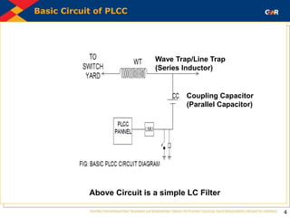
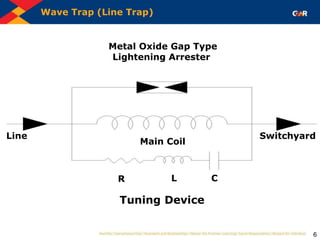
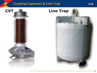
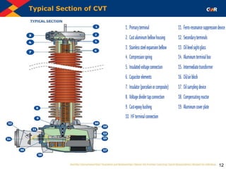
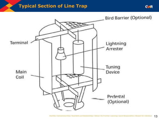
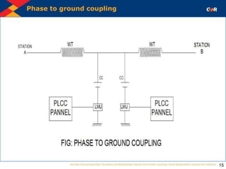
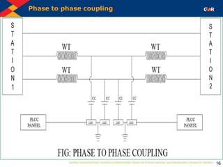
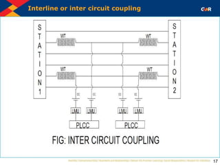
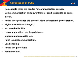
SlideShare a Scribd company logo
Why The Name PLCC
2
• The term PLCC abbreviates Power Line Carrier Communication since
conductors of Power Lines (132 kV, 220 kV, 400 kV and 765 kV Transmission
Lines) carry the high frequency communication signal also.
• In India the Power Frequency is 50 Hz & the Communication Frequency
ranges from 50 kHz to 500 kHz.
• A combination of Series Inductor (Line Trap) & Parallel Capacitor (Coupling
Capacitor) at both load as well source end are used, the combination of
Inductor & Capacitor discriminates between Power & Communication
Frequencies.
• Both end PLCCs communicate with each other and serve the purpose of
Monitoring & Protection of Transmission Line as well as Speech
Communication between both end Sub-Stations.
PLCC Familiarization
3
• Power line carrier communication is the method of transmitting information
using power network.
• The telephone communication system cannot be directly connected to the
high voltage lines, but PLCC facilitates the same.
• These usually consist of high voltage capacitor & inductor connected in
parallel used in conjunction with suitable line matching unit (LMU) for
matching the impedance of line to that of the coaxial cable connecting the
unit to the PLCC.
• LMU is a composite unit consisting of Drain Coil, Isolation transformer with
Lightning Arrester on its both the sides, a Tuning Device and an earth switch.
Tuning Device is the combination of R-L-C circuits which act as filter circuit.
LMU is also known as Coupling Device. Together with coupling capacitor,
LMU serves the purpose of connecting Audio/Radio frequency signals to
PLCC terminal and protection of the PLCC unit from the over voltages caused
due to transients on power system.
Basic Circuit of PLCC
4
Wave Trap/Line Trap
(Series Inductor)
Coupling Capacitor
(Parallel Capacitor)
Above Circuit is a simple LC Filter
Wave Trap and Coupling Capacitor
5
 The basic circuit of a PLCC consists of an Inductor connected in
series with the power circuit & a capacitor connected in parallel with
the power circuit.
• Wave Trap (Line Trap)-This equipment is installed at sub stations for
trapping the high frequency communication signals sent on the line
from remote end substation and diverting them to the telecom panels
in the sub station control room.
• Coupling Capacitor- This equipment is used in the sub stations where
communication is done by AC Power Line. It offers very low
impedance to high frequency carrier signal and allows them to enter
into the line matching unit and blocks the low frequency signals.
Wave Trap (Line Trap)
6
Metal Oxide Gap Type
Lightening Arrester
Main Coil
Line Switchyard
Tuning Device
R L C
Tuning Device
7
 The line traps are equipped with suitable tuning device to give the desired pass
band characteristics. The tuning device is shunt connected to the main coil and
protective device. The tuning device serves the purpose of obtaining relatively
high impedance for one or more frequencies or frequency bands.
 The tuning device shall consist of capacitor, inductor and resistor.
 The tuning device is so mounted that it can be easily changed without
removing the line traps.
 The tuning device is tuned and arranged in such a manner that there should not
be any significant alteration in the line traps blocking characteristics or any
physical damage due to either temperature rise or magnetic field of the main
coil at rated continuous current or rated short time current. The line traps are
designed for giving adjustable bandwidth by simple change of connection on
terminal blocks without removing the tuning device or line trap.
Capacitor Voltage Transformer
8
Function of Line Trap
9
The Inductive Reactance of an Inductor XL can be represented by the following
relation:
XL =ωL
=2πfL
Where:
XL is the Inductive Reactance of Inductor (Line Trap)
L is the Inductance of the Inductor (Line Trap)
Since the Inductive Reactance XL is proportional to the frequency, it will offer low
Reactance/Impedance to the lower frequencies & High Reactance/Impedance to
the higher frequencies & will allow the Power Frequency (50 Hz) to pass through
Function of Coupling Capacitor
10
The Capacitive Reactance of an Inductor XC can be represented by the following
relation:
XC =ωC
=1/2πfC
Where:
XC is the Capacitive Reactance of Capacitor (Coupling Capacitor)
C is the Capacitance of the Capacitor (Coupling Capacitor)
Since the Capacitive Reactance XC is inversely proportional to the frequency, it
will offer high Reactance/Impedance to the lower frequencies & low
Reactance/Impedance to the higher frequencies & will allow the communication
frequencies (50-500 kHz) to pass through.
Coupling Capacitor & Line Trap
11
CVT Line Trap
Typical Section of CVT
12
Typical Section of Line Trap
13
Types of Coupling
14
 Phase to ground coupling
 Phase to phase coupling
 Interline or inter circuit coupling
Phase to ground coupling
15
Phase to phase coupling
16
Interline or inter circuit coupling
17
Advantages of PLCC
18
• No separate wires are needed for communication purpose.
• Both communication and power transfer can be possible on same
circuit.
• Power lines provides the shortest route between the power station.
• Higher mechanical strength.
• Increased reliability.
• Lower attenuation over long distance.
• Implementation cost is low.
• Point to point communication.
• Load shading.
• Power line protection.
• Fault indicator.
Disadvantages of PLCC
19
• Interference are produced on associated communication lines. This
increases attenuation of signals.
• High voltage lines have transformer connections, which attenuate
carrier signals.
• Noise introduced in power lines carrying communication signals is
more than compared to telephone lines.
OPGW (Optical Ground Wire)
20
• Now a days PLCCs are replaced by OPGW.
• OPGW abbreviates Optical Ground Wire.
• Optical Ground Wire acts as normal ground wire protecting phase
wires from lightning strikes and carries earth fault current.
• Apart from its application as an earth wire, OPGW also provides an
optical path in power line installations for telecommunication &
protection needs.
• OPGW can be installed in the same manner as normal ground wire
with conventional resources.
• OPGW eliminates the Coupling Capacitor & Line Trap thereby
reducing the system complexity and enhancing the reliability.
Cross-section of OPGW
21
OPGW cross section
22
23

More Related Content

Similar to Power_Line_Carrier_Communication.pptx

CSPTCL DANGANIYA RAIPUR (C.G.)
CSPTCL   DANGANIYA RAIPUR (C.G.)CSPTCL   DANGANIYA RAIPUR (C.G.)
CSPTCL DANGANIYA RAIPUR (C.G.)
Government Engineering College, Raipur
 
Power line carrier communication(with awesome animation work)
Power line carrier communication(with awesome animation work)Power line carrier communication(with awesome animation work)
Power line carrier communication(with awesome animation work)
Mohit Agarwal
 
Plcc
PlccPlcc
Plcc presentation
Plcc presentationPlcc presentation
Plcc presentation
MAHESH SONI
 
Substation
SubstationSubstation
PLCC.ppt
PLCC.pptPLCC.ppt
PLCC.ppt
thomas victor
 
Track 2 session 6 - st dev con 2016 - wireless charging technologies
Track 2   session 6 - st dev con 2016 - wireless charging technologies Track 2   session 6 - st dev con 2016 - wireless charging technologies
Track 2 session 6 - st dev con 2016 - wireless charging technologies
ST_World
 
Power Line Carrier Communication
Power Line Carrier CommunicationPower Line Carrier Communication
Power Line Carrier Communication
Neha Gethe
 
Substations
Substations Substations
Substations
Engr Muhammad Imran
 
Low frequency ac transmission for power systems by Aamir Saleem
Low frequency ac transmission for power systems by Aamir SaleemLow frequency ac transmission for power systems by Aamir Saleem
Low frequency ac transmission for power systems by Aamir Saleem
Aamir Saleem
 
Data Transmission through Energy Coil of Wireless Power Transfer System
Data Transmission through Energy Coil of  Wireless Power Transfer SystemData Transmission through Energy Coil of  Wireless Power Transfer System
Data Transmission through Energy Coil of Wireless Power Transfer System
vivek guptha
 
Power line carrier communication
Power  line  carrier  communicationPower  line  carrier  communication
Power line carrier communication
Rahul Mehta
 
substation internship report
substation internship report substation internship report
substation internship report
Arun Thapa
 
THD ANALYSIS OF LFAC TRANSMISSION SYSTEM
THD ANALYSIS OF LFAC TRANSMISSION SYSTEMTHD ANALYSIS OF LFAC TRANSMISSION SYSTEM
THD ANALYSIS OF LFAC TRANSMISSION SYSTEM
ijiert bestjournal
 
Power Line Carrier Communication
Power Line Carrier CommunicationPower Line Carrier Communication
Power Line Carrier CommunicationBiswajit Pratihari
 
Powerlinecarrier (3)
Powerlinecarrier (3)Powerlinecarrier (3)
Powerlinecarrier (3)ajay901551
 
Flexible AC Transmitter by using TSR
Flexible AC Transmitter by using TSR Flexible AC Transmitter by using TSR
Flexible AC Transmitter by using TSR
AmeerHamza842286
 
Study tour to optcl
Study tour to optclStudy tour to optcl
Study tour to optcl
SoumyaRanjanDas13
 
RGPV EX7102 unit I
RGPV EX7102 unit IRGPV EX7102 unit I
RGPV EX7102 unit I
Mani Deep Dutt
 

Similar to Power_Line_Carrier_Communication.pptx (20)

CSPTCL DANGANIYA RAIPUR (C.G.)
CSPTCL   DANGANIYA RAIPUR (C.G.)CSPTCL   DANGANIYA RAIPUR (C.G.)
CSPTCL DANGANIYA RAIPUR (C.G.)
 
Power line carrier communication(with awesome animation work)
Power line carrier communication(with awesome animation work)Power line carrier communication(with awesome animation work)
Power line carrier communication(with awesome animation work)
 
Plcc
PlccPlcc
Plcc
 
Plcc presentation
Plcc presentationPlcc presentation
Plcc presentation
 
Substation
SubstationSubstation
Substation
 
PLCC.ppt
PLCC.pptPLCC.ppt
PLCC.ppt
 
Track 2 session 6 - st dev con 2016 - wireless charging technologies
Track 2   session 6 - st dev con 2016 - wireless charging technologies Track 2   session 6 - st dev con 2016 - wireless charging technologies
Track 2 session 6 - st dev con 2016 - wireless charging technologies
 
Power Line Carrier Communication
Power Line Carrier CommunicationPower Line Carrier Communication
Power Line Carrier Communication
 
Substations
Substations Substations
Substations
 
Low frequency ac transmission for power systems by Aamir Saleem
Low frequency ac transmission for power systems by Aamir SaleemLow frequency ac transmission for power systems by Aamir Saleem
Low frequency ac transmission for power systems by Aamir Saleem
 
Ppt
PptPpt
Ppt
 
Data Transmission through Energy Coil of Wireless Power Transfer System
Data Transmission through Energy Coil of  Wireless Power Transfer SystemData Transmission through Energy Coil of  Wireless Power Transfer System
Data Transmission through Energy Coil of Wireless Power Transfer System
 
Power line carrier communication
Power  line  carrier  communicationPower  line  carrier  communication
Power line carrier communication
 
substation internship report
substation internship report substation internship report
substation internship report
 
THD ANALYSIS OF LFAC TRANSMISSION SYSTEM
THD ANALYSIS OF LFAC TRANSMISSION SYSTEMTHD ANALYSIS OF LFAC TRANSMISSION SYSTEM
THD ANALYSIS OF LFAC TRANSMISSION SYSTEM
 
Power Line Carrier Communication
Power Line Carrier CommunicationPower Line Carrier Communication
Power Line Carrier Communication
 
Powerlinecarrier (3)
Powerlinecarrier (3)Powerlinecarrier (3)
Powerlinecarrier (3)
 
Flexible AC Transmitter by using TSR
Flexible AC Transmitter by using TSR Flexible AC Transmitter by using TSR
Flexible AC Transmitter by using TSR
 
Study tour to optcl
Study tour to optclStudy tour to optcl
Study tour to optcl
 
RGPV EX7102 unit I
RGPV EX7102 unit IRGPV EX7102 unit I
RGPV EX7102 unit I
 

More from Vara Prasad

switching theory and logical design for ece
switching theory and logical design for eceswitching theory and logical design for ece
switching theory and logical design for ece
Vara Prasad
 
interduction to electrical power systems
interduction  to electrical power systemsinterduction  to electrical power systems
interduction to electrical power systems
Vara Prasad
 
high voltge engineering useful for diploma
high voltge engineering useful for diplomahigh voltge engineering useful for diploma
high voltge engineering useful for diploma
Vara Prasad
 
power point presentation on high voltage
power point presentation on high voltagepower point presentation on high voltage
power point presentation on high voltage
Vara Prasad
 
PPTChapter12.pdf
PPTChapter12.pdfPPTChapter12.pdf
PPTChapter12.pdf
Vara Prasad
 
EE504.9.ppt
EE504.9.pptEE504.9.ppt
EE504.9.ppt
Vara Prasad
 
EE504.5.ppt
EE504.5.pptEE504.5.ppt
EE504.5.ppt
Vara Prasad
 
EE504.2.ppt
EE504.2.pptEE504.2.ppt
EE504.2.ppt
Vara Prasad
 
EE503.29.ppt
EE503.29.pptEE503.29.ppt
EE503.29.ppt
Vara Prasad
 
EE504.74.ppt
EE504.74.pptEE504.74.ppt
EE504.74.ppt
Vara Prasad
 
EE504.75.ppt
EE504.75.pptEE504.75.ppt
EE504.75.ppt
Vara Prasad
 
EE504.1.ppt
EE504.1.pptEE504.1.ppt
EE504.1.ppt
Vara Prasad
 
EM material eee.ppt
EM material eee.pptEM material eee.ppt
EM material eee.ppt
Vara Prasad
 
GRSP-49-28e.ppt
GRSP-49-28e.pptGRSP-49-28e.ppt
GRSP-49-28e.ppt
Vara Prasad
 
Capacitors with Dielectrics.ppt
Capacitors with Dielectrics.pptCapacitors with Dielectrics.ppt
Capacitors with Dielectrics.ppt
Vara Prasad
 
Maxwell.ppt
Maxwell.pptMaxwell.ppt
Maxwell.ppt
Vara Prasad
 
tutorial.ppt
tutorial.ppttutorial.ppt
tutorial.ppt
Vara Prasad
 
Class 13-Long-Duration Voltage Variations.ppt
Class 13-Long-Duration Voltage Variations.pptClass 13-Long-Duration Voltage Variations.ppt
Class 13-Long-Duration Voltage Variations.ppt
Vara Prasad
 
EE394V_DG_Week6.ppt
EE394V_DG_Week6.pptEE394V_DG_Week6.ppt
EE394V_DG_Week6.ppt
Vara Prasad
 
Oxford_citizens_assembly_Eyre_final.pptx
Oxford_citizens_assembly_Eyre_final.pptxOxford_citizens_assembly_Eyre_final.pptx
Oxford_citizens_assembly_Eyre_final.pptx
Vara Prasad
 

More from Vara Prasad (20)

switching theory and logical design for ece
switching theory and logical design for eceswitching theory and logical design for ece
switching theory and logical design for ece
 
interduction to electrical power systems
interduction  to electrical power systemsinterduction  to electrical power systems
interduction to electrical power systems
 
high voltge engineering useful for diploma
high voltge engineering useful for diplomahigh voltge engineering useful for diploma
high voltge engineering useful for diploma
 
power point presentation on high voltage
power point presentation on high voltagepower point presentation on high voltage
power point presentation on high voltage
 
PPTChapter12.pdf
PPTChapter12.pdfPPTChapter12.pdf
PPTChapter12.pdf
 
EE504.9.ppt
EE504.9.pptEE504.9.ppt
EE504.9.ppt
 
EE504.5.ppt
EE504.5.pptEE504.5.ppt
EE504.5.ppt
 
EE504.2.ppt
EE504.2.pptEE504.2.ppt
EE504.2.ppt
 
EE503.29.ppt
EE503.29.pptEE503.29.ppt
EE503.29.ppt
 
EE504.74.ppt
EE504.74.pptEE504.74.ppt
EE504.74.ppt
 
EE504.75.ppt
EE504.75.pptEE504.75.ppt
EE504.75.ppt
 
EE504.1.ppt
EE504.1.pptEE504.1.ppt
EE504.1.ppt
 
EM material eee.ppt
EM material eee.pptEM material eee.ppt
EM material eee.ppt
 
GRSP-49-28e.ppt
GRSP-49-28e.pptGRSP-49-28e.ppt
GRSP-49-28e.ppt
 
Capacitors with Dielectrics.ppt
Capacitors with Dielectrics.pptCapacitors with Dielectrics.ppt
Capacitors with Dielectrics.ppt
 
Maxwell.ppt
Maxwell.pptMaxwell.ppt
Maxwell.ppt
 
tutorial.ppt
tutorial.ppttutorial.ppt
tutorial.ppt
 
Class 13-Long-Duration Voltage Variations.ppt
Class 13-Long-Duration Voltage Variations.pptClass 13-Long-Duration Voltage Variations.ppt
Class 13-Long-Duration Voltage Variations.ppt
 
EE394V_DG_Week6.ppt
EE394V_DG_Week6.pptEE394V_DG_Week6.ppt
EE394V_DG_Week6.ppt
 
Oxford_citizens_assembly_Eyre_final.pptx
Oxford_citizens_assembly_Eyre_final.pptxOxford_citizens_assembly_Eyre_final.pptx
Oxford_citizens_assembly_Eyre_final.pptx
 

Recently uploaded

Student information management system project report ii.pdf
Student information management system project report ii.pdfStudent information management system project report ii.pdf
Student information management system project report ii.pdf
Kamal Acharya
 
Sachpazis:Terzaghi Bearing Capacity Estimation in simple terms with Calculati...
Sachpazis:Terzaghi Bearing Capacity Estimation in simple terms with Calculati...Sachpazis:Terzaghi Bearing Capacity Estimation in simple terms with Calculati...
Sachpazis:Terzaghi Bearing Capacity Estimation in simple terms with Calculati...
Dr.Costas Sachpazis
 
Pile Foundation by Venkatesh Taduvai (Sub Geotechnical Engineering II)-conver...
Pile Foundation by Venkatesh Taduvai (Sub Geotechnical Engineering II)-conver...Pile Foundation by Venkatesh Taduvai (Sub Geotechnical Engineering II)-conver...
Pile Foundation by Venkatesh Taduvai (Sub Geotechnical Engineering II)-conver...
AJAYKUMARPUND1
 
RAT: Retrieval Augmented Thoughts Elicit Context-Aware Reasoning in Long-Hori...
RAT: Retrieval Augmented Thoughts Elicit Context-Aware Reasoning in Long-Hori...RAT: Retrieval Augmented Thoughts Elicit Context-Aware Reasoning in Long-Hori...
RAT: Retrieval Augmented Thoughts Elicit Context-Aware Reasoning in Long-Hori...
thanhdowork
 
AKS UNIVERSITY Satna Final Year Project By OM Hardaha.pdf
AKS UNIVERSITY Satna Final Year Project By OM Hardaha.pdfAKS UNIVERSITY Satna Final Year Project By OM Hardaha.pdf
AKS UNIVERSITY Satna Final Year Project By OM Hardaha.pdf
SamSarthak3
 
Hybrid optimization of pumped hydro system and solar- Engr. Abdul-Azeez.pdf
Hybrid optimization of pumped hydro system and solar- Engr. Abdul-Azeez.pdfHybrid optimization of pumped hydro system and solar- Engr. Abdul-Azeez.pdf
Hybrid optimization of pumped hydro system and solar- Engr. Abdul-Azeez.pdf
fxintegritypublishin
 
Design and Analysis of Algorithms-DP,Backtracking,Graphs,B&B
Design and Analysis of Algorithms-DP,Backtracking,Graphs,B&BDesign and Analysis of Algorithms-DP,Backtracking,Graphs,B&B
Design and Analysis of Algorithms-DP,Backtracking,Graphs,B&B
Sreedhar Chowdam
 
CFD Simulation of By-pass Flow in a HRSG module by R&R Consult.pptx
CFD Simulation of By-pass Flow in a HRSG module by R&R Consult.pptxCFD Simulation of By-pass Flow in a HRSG module by R&R Consult.pptx
CFD Simulation of By-pass Flow in a HRSG module by R&R Consult.pptx
R&R Consult
 
HYDROPOWER - Hydroelectric power generation
HYDROPOWER - Hydroelectric power generationHYDROPOWER - Hydroelectric power generation
HYDROPOWER - Hydroelectric power generation
Robbie Edward Sayers
 
Industrial Training at Shahjalal Fertilizer Company Limited (SFCL)
Industrial Training at Shahjalal Fertilizer Company Limited (SFCL)Industrial Training at Shahjalal Fertilizer Company Limited (SFCL)
Industrial Training at Shahjalal Fertilizer Company Limited (SFCL)
MdTanvirMahtab2
 
一比一原版(IIT毕业证)伊利诺伊理工大学毕业证成绩单专业办理
一比一原版(IIT毕业证)伊利诺伊理工大学毕业证成绩单专业办理一比一原版(IIT毕业证)伊利诺伊理工大学毕业证成绩单专业办理
一比一原版(IIT毕业证)伊利诺伊理工大学毕业证成绩单专业办理
zwunae
 
Immunizing Image Classifiers Against Localized Adversary Attacks
Immunizing Image Classifiers Against Localized Adversary AttacksImmunizing Image Classifiers Against Localized Adversary Attacks
Immunizing Image Classifiers Against Localized Adversary Attacks
gerogepatton
 
NO1 Uk best vashikaran specialist in delhi vashikaran baba near me online vas...
NO1 Uk best vashikaran specialist in delhi vashikaran baba near me online vas...NO1 Uk best vashikaran specialist in delhi vashikaran baba near me online vas...
NO1 Uk best vashikaran specialist in delhi vashikaran baba near me online vas...
Amil Baba Dawood bangali
 
在线办理(ANU毕业证书)澳洲国立大学毕业证录取通知书一模一样
在线办理(ANU毕业证书)澳洲国立大学毕业证录取通知书一模一样在线办理(ANU毕业证书)澳洲国立大学毕业证录取通知书一模一样
在线办理(ANU毕业证书)澳洲国立大学毕业证录取通知书一模一样
obonagu
 
Planning Of Procurement o different goods and services
Planning Of Procurement o different goods and servicesPlanning Of Procurement o different goods and services
Planning Of Procurement o different goods and services
JoytuBarua2
 
Runway Orientation Based on the Wind Rose Diagram.pptx
Runway Orientation Based on the Wind Rose Diagram.pptxRunway Orientation Based on the Wind Rose Diagram.pptx
Runway Orientation Based on the Wind Rose Diagram.pptx
SupreethSP4
 
Hierarchical Digital Twin of a Naval Power System
Hierarchical Digital Twin of a Naval Power SystemHierarchical Digital Twin of a Naval Power System
Hierarchical Digital Twin of a Naval Power System
Kerry Sado
 
Architectural Portfolio Sean Lockwood
Architectural Portfolio Sean LockwoodArchitectural Portfolio Sean Lockwood
Architectural Portfolio Sean Lockwood
seandesed
 
Governing Equations for Fundamental Aerodynamics_Anderson2010.pdf
Governing Equations for Fundamental Aerodynamics_Anderson2010.pdfGoverning Equations for Fundamental Aerodynamics_Anderson2010.pdf
Governing Equations for Fundamental Aerodynamics_Anderson2010.pdf
WENKENLI1
 
CME397 Surface Engineering- Professional Elective
CME397 Surface Engineering- Professional ElectiveCME397 Surface Engineering- Professional Elective
CME397 Surface Engineering- Professional Elective
karthi keyan
 

Recently uploaded (20)

Student information management system project report ii.pdf
Student information management system project report ii.pdfStudent information management system project report ii.pdf
Student information management system project report ii.pdf
 
Sachpazis:Terzaghi Bearing Capacity Estimation in simple terms with Calculati...
Sachpazis:Terzaghi Bearing Capacity Estimation in simple terms with Calculati...Sachpazis:Terzaghi Bearing Capacity Estimation in simple terms with Calculati...
Sachpazis:Terzaghi Bearing Capacity Estimation in simple terms with Calculati...
 
Pile Foundation by Venkatesh Taduvai (Sub Geotechnical Engineering II)-conver...
Pile Foundation by Venkatesh Taduvai (Sub Geotechnical Engineering II)-conver...Pile Foundation by Venkatesh Taduvai (Sub Geotechnical Engineering II)-conver...
Pile Foundation by Venkatesh Taduvai (Sub Geotechnical Engineering II)-conver...
 
RAT: Retrieval Augmented Thoughts Elicit Context-Aware Reasoning in Long-Hori...
RAT: Retrieval Augmented Thoughts Elicit Context-Aware Reasoning in Long-Hori...RAT: Retrieval Augmented Thoughts Elicit Context-Aware Reasoning in Long-Hori...
RAT: Retrieval Augmented Thoughts Elicit Context-Aware Reasoning in Long-Hori...
 
AKS UNIVERSITY Satna Final Year Project By OM Hardaha.pdf
AKS UNIVERSITY Satna Final Year Project By OM Hardaha.pdfAKS UNIVERSITY Satna Final Year Project By OM Hardaha.pdf
AKS UNIVERSITY Satna Final Year Project By OM Hardaha.pdf
 
Hybrid optimization of pumped hydro system and solar- Engr. Abdul-Azeez.pdf
Hybrid optimization of pumped hydro system and solar- Engr. Abdul-Azeez.pdfHybrid optimization of pumped hydro system and solar- Engr. Abdul-Azeez.pdf
Hybrid optimization of pumped hydro system and solar- Engr. Abdul-Azeez.pdf
 
Design and Analysis of Algorithms-DP,Backtracking,Graphs,B&B
Design and Analysis of Algorithms-DP,Backtracking,Graphs,B&BDesign and Analysis of Algorithms-DP,Backtracking,Graphs,B&B
Design and Analysis of Algorithms-DP,Backtracking,Graphs,B&B
 
CFD Simulation of By-pass Flow in a HRSG module by R&R Consult.pptx
CFD Simulation of By-pass Flow in a HRSG module by R&R Consult.pptxCFD Simulation of By-pass Flow in a HRSG module by R&R Consult.pptx
CFD Simulation of By-pass Flow in a HRSG module by R&R Consult.pptx
 
HYDROPOWER - Hydroelectric power generation
HYDROPOWER - Hydroelectric power generationHYDROPOWER - Hydroelectric power generation
HYDROPOWER - Hydroelectric power generation
 
Industrial Training at Shahjalal Fertilizer Company Limited (SFCL)
Industrial Training at Shahjalal Fertilizer Company Limited (SFCL)Industrial Training at Shahjalal Fertilizer Company Limited (SFCL)
Industrial Training at Shahjalal Fertilizer Company Limited (SFCL)
 
一比一原版(IIT毕业证)伊利诺伊理工大学毕业证成绩单专业办理
一比一原版(IIT毕业证)伊利诺伊理工大学毕业证成绩单专业办理一比一原版(IIT毕业证)伊利诺伊理工大学毕业证成绩单专业办理
一比一原版(IIT毕业证)伊利诺伊理工大学毕业证成绩单专业办理
 
Immunizing Image Classifiers Against Localized Adversary Attacks
Immunizing Image Classifiers Against Localized Adversary AttacksImmunizing Image Classifiers Against Localized Adversary Attacks
Immunizing Image Classifiers Against Localized Adversary Attacks
 
NO1 Uk best vashikaran specialist in delhi vashikaran baba near me online vas...
NO1 Uk best vashikaran specialist in delhi vashikaran baba near me online vas...NO1 Uk best vashikaran specialist in delhi vashikaran baba near me online vas...
NO1 Uk best vashikaran specialist in delhi vashikaran baba near me online vas...
 
在线办理(ANU毕业证书)澳洲国立大学毕业证录取通知书一模一样
在线办理(ANU毕业证书)澳洲国立大学毕业证录取通知书一模一样在线办理(ANU毕业证书)澳洲国立大学毕业证录取通知书一模一样
在线办理(ANU毕业证书)澳洲国立大学毕业证录取通知书一模一样
 
Planning Of Procurement o different goods and services
Planning Of Procurement o different goods and servicesPlanning Of Procurement o different goods and services
Planning Of Procurement o different goods and services
 
Runway Orientation Based on the Wind Rose Diagram.pptx
Runway Orientation Based on the Wind Rose Diagram.pptxRunway Orientation Based on the Wind Rose Diagram.pptx
Runway Orientation Based on the Wind Rose Diagram.pptx
 
Hierarchical Digital Twin of a Naval Power System
Hierarchical Digital Twin of a Naval Power SystemHierarchical Digital Twin of a Naval Power System
Hierarchical Digital Twin of a Naval Power System
 
Architectural Portfolio Sean Lockwood
Architectural Portfolio Sean LockwoodArchitectural Portfolio Sean Lockwood
Architectural Portfolio Sean Lockwood
 
Governing Equations for Fundamental Aerodynamics_Anderson2010.pdf
Governing Equations for Fundamental Aerodynamics_Anderson2010.pdfGoverning Equations for Fundamental Aerodynamics_Anderson2010.pdf
Governing Equations for Fundamental Aerodynamics_Anderson2010.pdf
 
CME397 Surface Engineering- Professional Elective
CME397 Surface Engineering- Professional ElectiveCME397 Surface Engineering- Professional Elective
CME397 Surface Engineering- Professional Elective
 

Power_Line_Carrier_Communication.pptx

  • 1.
  • 2. Why The Name PLCC 2 • The term PLCC abbreviates Power Line Carrier Communication since conductors of Power Lines (132 kV, 220 kV, 400 kV and 765 kV Transmission Lines) carry the high frequency communication signal also. • In India the Power Frequency is 50 Hz & the Communication Frequency ranges from 50 kHz to 500 kHz. • A combination of Series Inductor (Line Trap) & Parallel Capacitor (Coupling Capacitor) at both load as well source end are used, the combination of Inductor & Capacitor discriminates between Power & Communication Frequencies. • Both end PLCCs communicate with each other and serve the purpose of Monitoring & Protection of Transmission Line as well as Speech Communication between both end Sub-Stations.
  • 3. PLCC Familiarization 3 • Power line carrier communication is the method of transmitting information using power network. • The telephone communication system cannot be directly connected to the high voltage lines, but PLCC facilitates the same. • These usually consist of high voltage capacitor & inductor connected in parallel used in conjunction with suitable line matching unit (LMU) for matching the impedance of line to that of the coaxial cable connecting the unit to the PLCC. • LMU is a composite unit consisting of Drain Coil, Isolation transformer with Lightning Arrester on its both the sides, a Tuning Device and an earth switch. Tuning Device is the combination of R-L-C circuits which act as filter circuit. LMU is also known as Coupling Device. Together with coupling capacitor, LMU serves the purpose of connecting Audio/Radio frequency signals to PLCC terminal and protection of the PLCC unit from the over voltages caused due to transients on power system.
  • 4. Basic Circuit of PLCC 4 Wave Trap/Line Trap (Series Inductor) Coupling Capacitor (Parallel Capacitor) Above Circuit is a simple LC Filter
  • 5. Wave Trap and Coupling Capacitor 5  The basic circuit of a PLCC consists of an Inductor connected in series with the power circuit & a capacitor connected in parallel with the power circuit. • Wave Trap (Line Trap)-This equipment is installed at sub stations for trapping the high frequency communication signals sent on the line from remote end substation and diverting them to the telecom panels in the sub station control room. • Coupling Capacitor- This equipment is used in the sub stations where communication is done by AC Power Line. It offers very low impedance to high frequency carrier signal and allows them to enter into the line matching unit and blocks the low frequency signals.
  • 6. Wave Trap (Line Trap) 6 Metal Oxide Gap Type Lightening Arrester Main Coil Line Switchyard Tuning Device R L C
  • 7. Tuning Device 7  The line traps are equipped with suitable tuning device to give the desired pass band characteristics. The tuning device is shunt connected to the main coil and protective device. The tuning device serves the purpose of obtaining relatively high impedance for one or more frequencies or frequency bands.  The tuning device shall consist of capacitor, inductor and resistor.  The tuning device is so mounted that it can be easily changed without removing the line traps.  The tuning device is tuned and arranged in such a manner that there should not be any significant alteration in the line traps blocking characteristics or any physical damage due to either temperature rise or magnetic field of the main coil at rated continuous current or rated short time current. The line traps are designed for giving adjustable bandwidth by simple change of connection on terminal blocks without removing the tuning device or line trap.
  • 9. Function of Line Trap 9 The Inductive Reactance of an Inductor XL can be represented by the following relation: XL =ωL =2πfL Where: XL is the Inductive Reactance of Inductor (Line Trap) L is the Inductance of the Inductor (Line Trap) Since the Inductive Reactance XL is proportional to the frequency, it will offer low Reactance/Impedance to the lower frequencies & High Reactance/Impedance to the higher frequencies & will allow the Power Frequency (50 Hz) to pass through
  • 10. Function of Coupling Capacitor 10 The Capacitive Reactance of an Inductor XC can be represented by the following relation: XC =ωC =1/2πfC Where: XC is the Capacitive Reactance of Capacitor (Coupling Capacitor) C is the Capacitance of the Capacitor (Coupling Capacitor) Since the Capacitive Reactance XC is inversely proportional to the frequency, it will offer high Reactance/Impedance to the lower frequencies & low Reactance/Impedance to the higher frequencies & will allow the communication frequencies (50-500 kHz) to pass through.
  • 11. Coupling Capacitor & Line Trap 11 CVT Line Trap
  • 13. Typical Section of Line Trap 13
  • 14. Types of Coupling 14  Phase to ground coupling  Phase to phase coupling  Interline or inter circuit coupling
  • 15. Phase to ground coupling 15
  • 16. Phase to phase coupling 16
  • 17. Interline or inter circuit coupling 17
  • 18. Advantages of PLCC 18 • No separate wires are needed for communication purpose. • Both communication and power transfer can be possible on same circuit. • Power lines provides the shortest route between the power station. • Higher mechanical strength. • Increased reliability. • Lower attenuation over long distance. • Implementation cost is low. • Point to point communication. • Load shading. • Power line protection. • Fault indicator.
  • 19. Disadvantages of PLCC 19 • Interference are produced on associated communication lines. This increases attenuation of signals. • High voltage lines have transformer connections, which attenuate carrier signals. • Noise introduced in power lines carrying communication signals is more than compared to telephone lines.
  • 20. OPGW (Optical Ground Wire) 20 • Now a days PLCCs are replaced by OPGW. • OPGW abbreviates Optical Ground Wire. • Optical Ground Wire acts as normal ground wire protecting phase wires from lightning strikes and carries earth fault current. • Apart from its application as an earth wire, OPGW also provides an optical path in power line installations for telecommunication & protection needs. • OPGW can be installed in the same manner as normal ground wire with conventional resources. • OPGW eliminates the Coupling Capacitor & Line Trap thereby reducing the system complexity and enhancing the reliability.
  • 23. 23