Downloaded 343 times
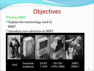

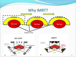
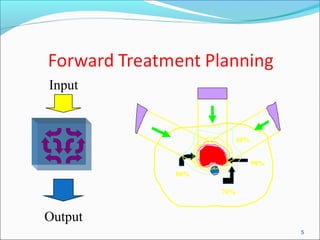
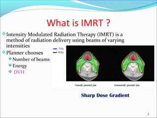
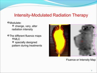

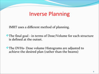
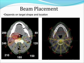
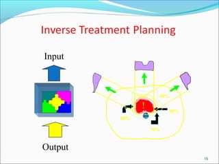
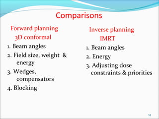


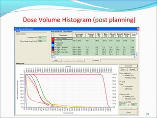


IMRT is an advanced form of radiation therapy that uses modulated beam intensities to more precisely target tumors while reducing radiation exposure to surrounding healthy tissues. It involves inverse planning where dose and volume constraints for the tumor and organs at risk are specified upfront. The treatment planning system then optimizes beam fluence maps through multiple iterations to achieve the desired dose distribution. Final treatment delivery involves either segmented or dynamic modulation of the multileaf collimator to sculpt the radiation beam according to the optimal fluence map calculated during planning.


![Arc therapy [autosaved] [autosaved]](https://cdn.slidesharecdn.com/ss_thumbnails/arctherapyautosavedautosaved-150423125828-conversion-gate01-thumbnail.jpg?width=640&height=640&fit=bounds)


