Design of concrete structures-I- Design Steps
•
3 likes•542 views

as per Shivaji University curriculum the design/analysis steps for DCS-I Subject

Recommended
More Related Content
What's hot
What's hot (20)
Similar to Design of concrete structures-I- Design Steps
Similar to Design of concrete structures-I- Design Steps (9)
More from DYPCET
More from DYPCET (17)
Recently uploaded
Recently uploaded (20)
Design of concrete structures-I- Design Steps
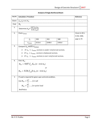
- 1. Design of Concrete Structure-I 2017 Mr. P. P. Prabhu Page 1 Analysis of Singly Reinforced Beam Step No. Calculation / Procedure Reference Given: 𝑓 , 𝑓 , 𝑏, 𝑑, 𝐴 Find: 𝑀 1. Determine 𝑥 = . . , 2. Find 𝑥 𝑓 250 415 500 𝑥 0.53 d 0.48 d 0.46 d Clause no 38.1, IS 456: 2000, page no 70 3. Compare 𝑥 𝑤𝑖𝑡ℎ 𝑥 𝐼𝐹 𝑥 < 𝑥 𝑠𝑒𝑐𝑡𝑖𝑜𝑛 𝑖𝑠 𝑢𝑛𝑑𝑒𝑟 𝑟𝑒𝑖𝑛𝑓𝑜𝑟𝑐𝑒𝑑 𝑠𝑒𝑐𝑡𝑖𝑜𝑛. 𝐼𝐹 𝑥 = 𝑥 𝑠𝑒𝑐𝑡𝑖𝑜𝑛 𝑖𝑠 𝑏𝑎𝑙𝑎𝑛𝑐𝑒𝑑 𝑠𝑒𝑐𝑡𝑖𝑜𝑛. 𝐼𝐹 𝑥 > 𝑥 𝑠𝑒𝑐𝑡𝑖𝑜𝑛 𝑖𝑠 𝑜𝑣𝑒𝑟 𝑟𝑒𝑖𝑛𝑓𝑜𝑟𝑐𝑒𝑑 𝑠𝑒𝑐𝑡𝑖𝑜𝑛. 4. Find 𝑀 𝑀 = 0.87 𝑓 𝑦 𝐴 𝑠𝑡 (𝑑 − 0.42 𝑥 𝑢) 𝑜𝑟 𝑀 = 0.36 𝑓 𝑐𝑘 𝑏 𝑥 𝑢 (𝑑 − 0.42 𝑥 𝑢) 5 If Load is required for given span and end condition, Use 𝑀 = … . . 𝑓𝑜𝑟 𝑢𝑑𝑙 𝑀 = 𝑤𝑙 4 … . . 𝑓𝑜𝑟 𝑝𝑜𝑖𝑛𝑡 𝑙𝑜𝑎𝑑 And find w
- 2. Design of Concrete Structure-I 2017 Mr. P. P. Prabhu Page 2 Design of Singly Reinforced Beam Step No. Calculation / Procedure Reference Given: 𝑓 , 𝑓 , 𝑏, 𝐷, 𝑀 Find: 𝐴 1. Assume effective cover d’ Find d = D-d’ Clause no 26.4.2, IS 456: 2000, page no 47, Table no.16 2. Find 𝑀 𝑢𝑟 𝑓 250 415 500 𝑀 0.149𝑓 𝑏𝑑 0.138𝑓 𝑏𝑑 0.133𝑓 𝑏𝑑 3. Compare 𝑀 𝑤𝑖𝑡ℎ 𝑀 𝐼𝑓 𝑀 𝑢 < 𝑀 𝑠𝑒𝑐𝑡𝑖𝑜𝑛 𝑖𝑠 𝑢𝑛𝑑𝑒𝑟 𝑟𝑒𝑖𝑛𝑓𝑜𝑟𝑐𝑒𝑑 𝑠𝑒𝑐𝑡𝑖𝑜𝑛. 𝐼𝑓 𝑀 > 𝑀 𝑢𝑟𝑚𝑎𝑥 𝑠𝑒𝑐𝑡𝑖𝑜𝑛 𝑖𝑠 𝑜𝑣𝑒𝑟 𝑟𝑒𝑖𝑛𝑓𝑜𝑟𝑐𝑒𝑑 𝑠𝑒𝑐𝑡𝑖𝑜𝑛. 4. 𝐹𝑖𝑛𝑑 𝐴 𝐴 = 0.5 𝑓 𝑓 × 1 − 1 − 4.6 𝑀 𝑓 𝑏 𝑑 × 𝑏 𝑑
- 3. Design of Concrete Structure-I 2017 Mr. P. P. Prabhu Page 3 Analysis of Doubly Reinforced Beam Step No. Calculation / Procedure Reference Given: 𝑓 , 𝑏, 𝑑 , 𝑑 , 𝐴 , 𝐴 , 𝒇 𝒚 = 𝟐𝟓𝟎* Find: 𝑀 1. 𝐴𝑠𝑠𝑢𝑚𝑒 𝑓 = 0.87𝑓 Determine 𝑥 = . . . , 2. Find 𝑥 𝑓 250 415 500 𝑥 0.53 d 0.48 d 0.46 d Clause no 38.1, IS 456: 2000, page no 70 3. Compare 𝑥 𝑤𝑖𝑡ℎ 𝑥 𝐼𝐹 𝑥 < 𝑥 𝑠𝑒𝑐𝑡𝑖𝑜𝑛 𝑖𝑠 𝑢𝑛𝑑𝑒𝑟 𝑟𝑒𝑖𝑛𝑓𝑜𝑟𝑐𝑒𝑑 𝑠𝑒𝑐𝑡𝑖𝑜𝑛. 𝐼𝐹 𝑥 = 𝑥 𝑠𝑒𝑐𝑡𝑖𝑜𝑛 𝑖𝑠 𝑏𝑎𝑙𝑎𝑛𝑐𝑒𝑑 𝑠𝑒𝑐𝑡𝑖𝑜𝑛. 𝐼𝐹 𝑥 > 𝑥 𝑠𝑒𝑐𝑡𝑖𝑜𝑛 𝑖𝑠 𝑜𝑣𝑒𝑟 𝑟𝑒𝑖𝑛𝑓𝑜𝑟𝑐𝑒𝑑 𝑠𝑒𝑐𝑡𝑖𝑜𝑛. 𝐼𝑓 𝑥 > 𝑥 use 𝑥 =𝑥 4. Find 𝑓 = 700 (1 − 𝑑 𝑐 ) 𝐼𝑓 𝑓 ≥ 0.87 𝑓 assumption is correct. 𝐼𝑓 𝑓 < 0.87 𝑓 assumption is wrong Find 𝑥 𝑓𝑟𝑜𝑚 𝑡ℎ𝑖𝑠 𝑞𝑢𝑎𝑑𝑟𝑎𝑡𝑖𝑐 𝑒𝑞𝑎𝑡𝑖𝑜𝑛 0.36 𝑓 , 𝑏. 𝑥 + 700 1 − 𝑑 𝑐 . 𝐴 = 0.87 𝑓 . 𝐴 5 Compare 𝑥 𝑤𝑖𝑡ℎ 𝑥 𝐼𝐹 𝑥 < 𝑥 𝑠𝑒𝑐𝑡𝑖𝑜𝑛 𝑖𝑠 𝑢𝑛𝑑𝑒𝑟 𝑟𝑒𝑖𝑛𝑓𝑜𝑟𝑐𝑒𝑑 𝑠𝑒𝑐𝑡𝑖𝑜𝑛. 𝐼𝐹 𝑥 = 𝑥 𝑠𝑒𝑐𝑡𝑖𝑜𝑛 𝑖𝑠 𝑏𝑎𝑙𝑎𝑛𝑐𝑒𝑑 𝑠𝑒𝑐𝑡𝑖𝑜𝑛. 𝐼𝐹 𝑥 > 𝑥 𝑠𝑒𝑐𝑡𝑖𝑜𝑛 𝑖𝑠 𝑜𝑣𝑒𝑟 𝑟𝑒𝑖𝑛𝑓𝑜𝑟𝑐𝑒𝑑 𝑠𝑒𝑐𝑡𝑖𝑜𝑛. 6 Calculate 𝑓 𝑐𝑜𝑟𝑜𝑠𝑝𝑜𝑛𝑑𝑖𝑛𝑔 𝑡𝑜 𝑥 And find 𝑀 = 0.36 𝑓 𝑐𝑘 𝑏 𝑥 𝑢 (𝑑 − 0.42 𝑥 𝑢) + 𝑓 𝑠𝑐 𝐴 𝑠𝑐 𝑑 − 𝑑 𝑐
- 4. Design of Concrete Structure-I 2017 Mr. P. P. Prabhu Page 4 Design of Shear Reinforcement Step No. Calculation / Procedure Reference 1. Calculate Maximum Ultimate Shear 𝑉 = . 2. Calculate Design Shear 𝑉 = 𝑉 − 𝑤 ( + 𝑑) 𝑏 = 𝑤𝑖𝑑𝑡ℎ 𝑜𝑓 𝑠𝑢𝑝𝑝𝑜𝑟𝑡 d = effective depth of support 3. Obtain allowable ultimate shear 𝑉 𝑉 = 𝜏 . 𝑏. 𝑑 𝜏 𝑓𝑟𝑜𝑚 𝑡𝑎𝑏𝑙𝑒 20 Cl. No. 40.2.3 4. Check 𝑉 ≤ 𝑉 𝐼𝑓 𝑉 > 𝑉 𝑖𝑛𝑐𝑟𝑒𝑎𝑠𝑒 𝑡ℎ𝑒 𝑠𝑒𝑐𝑡𝑖𝑜𝑛 5. Calculate Shear resisted by Concrete , 𝑉 = 𝜏 . 𝑏. 𝑑 𝜏 𝑓𝑟𝑜𝑚 𝑡𝑎𝑏𝑙𝑒 19 Cl.No. 40.2.1 6. Find Ultimate Shear Resisted by Minimum Stirrups 𝑉 = 0.4 . 𝑏. 𝑑 7. Ultimate Shear Resisted by R.C.member 𝑉 = 𝑉 + 𝑉 8. If𝑉 < 𝑉 , Minimum Stirrups are sufficient Spacing between stirrups 𝑆 = . . . b width of beam For Spacing Cl.No. 40.4.a 9. 𝑉 > 𝑉 , Design Shear Reinforcement 1. Shear Resisted by Shear reinforcement 𝑉 = 𝑉 − 𝑉 2. If bent up bars are used , Calculate shear resisted by bent up bars, 𝑉 = 0.87 𝑓 . 𝐴 . 𝑠𝑖𝑛 ∝ ≤ 0.5𝑉 3. Ultimate Shear Resisted by Vertical stirrups 𝑉 = 𝑉 − 𝑉
- 5. Design of Concrete Structure-I 2017 Mr. P. P. Prabhu Page 5 𝐼𝑓 𝑏𝑒𝑛𝑡 𝑢𝑝 𝑏𝑎𝑟𝑠 𝑎𝑟𝑒 𝑛𝑜𝑡 𝑝𝑟𝑜𝑣𝑖𝑑𝑒𝑑 𝑉 = 𝑉 𝐹𝑖𝑛𝑑 𝑆𝑝𝑎𝑐𝑖𝑛𝑔 𝑆 = . . 𝑆 ≤ 0.75𝑑 𝑜𝑟 300𝑚𝑚 𝑤ℎ𝑖𝑐ℎ𝑒𝑣𝑒𝑟 𝑖𝑠 𝑙𝑒𝑠𝑠. 10. Reinforcement Details. dD Mainsteel t Clearspan ShearReinforcementDetails BentupBar Shearreinforcement Design of One Way Slab Step No. Calculation / Procedure Reference Slab Having > 2. Provide One Way slab. 1. Span: Depending upon condition determine effective span of slab. Cl. No. 22.2
- 6. Design of Concrete Structure-I 2017 Mr. P. P. Prabhu Page 6 2. Trial Depth : Calculate required depth 𝑑 = × . . Assume % Pt Fe 250 0.5 to 0.90 Fe 415 0.30 to 0.45 Fe 500 0.2 to 0.35 D = d + d’+ ∅ Find effective span = span + d Compare this with effective span from step no 1 Provide minimum of both. M.F. - Cl. No. 23.4, Fig no.4 - Cl. No. 23.2.1 3. Load Calculations: Consider 1 m width of slab. Dead Load / m = Self wt of slab + Floor Finish = 25. D + F.F. Live Load Total working Load ( 𝑊) = D.L. + L.L. Total Ultimate Load 𝑊 = 1.5 × 𝑊 4. Design Moment ( 𝑀 ) 𝑀 = 𝑊 . 𝑙 𝑒𝑓𝑓 8 5. Check for depth 𝑀 = 0.36 𝑓 𝑐𝑘 𝑏 𝑥 𝑢 𝑚𝑎𝑥 (𝑑 − 0.42 𝑥 𝑢 𝑚𝑎𝑥) 𝐼𝑓 𝑀 > 𝑀 Section is safe from bending moment consideration. If condition not satisfied, increase depth of section. 6. Main Steel A = 0.5 f f × 1 − 1 − 4.6 M f b d × b d For slab b = 1000mm A > A A = 0.15 % b. D … … … … … for mild steel A = 0.12 % b. D … … … … … for HYSD Spacing S = . 𝐹𝑜𝑟 𝐴 Cl. No.26.5.2.1
- 7. Design of Concrete Structure-I 2017 Mr. P. P. Prabhu Page 7 a = area of steel bar A = area of steel required S ≤ ( 3. d or 300 mm whichever is less) Hence provide … ∅ main steel @.... spacing c/c. 7. Check for Deflection: Find %Pt = . Find f = 0.58 f Find M.F. ………. From % Pt & f Calculate required depth d If d < d ………..Hence Safe. 8. Distribution Steel : A = 0.15 % b. D … … … … … for mild steel A = 0.12 % b. D … … … … … for HYSD Spacing S = 1000. a A S ≤ ( 5. d or 450 mm whichever is less) Hence provide … ∅ distribution steel @.... spacing c/c. 9. Check for Shear : Calculate Design Shear: 𝑉 = . Shear resisted by Concrete = 𝑉 = (𝜏 𝑘). 𝑏. 𝑑 𝑉 > 𝑉 … … … … … … . . 𝐻𝑒𝑛𝑐𝑒 𝑆𝑎𝑓𝑒. If not increase thickness of slab. 𝜏 𝑓𝑟𝑜𝑚 𝑇𝑎𝑏𝑙𝑒 19 𝑘 From Cl. No. 40.2.2.1 10. Check for Development length : 𝐿 𝐿 = .∅ . Check 𝐿 < . + 𝐿 Assume 𝐿 = − (𝑑 + ∅ ), 𝑀 = 𝑀 , 𝑉 = 𝑉 Cl. 26.2.1 11. Reinforcement Details:
- 8. Design of Concrete Structure-I 2017 Mr. P. P. Prabhu Page 8 d D D is t r i b u t i o n s t e e l M a in s t e e l t C l e a r s p a n R e i n f o r c e m e n t D e t a i l s i n o n e w a y s l a b 1 . 8 4 7 7 Design of Two Way Slab Step No. Calculation / Procedure Reference Slab Having < 2. Provide Two Way slab.
- 9. Design of Concrete Structure-I 2017 Mr. P. P. Prabhu Page 9 1. Span: Depending upon condition determine effective span of slab. Cl. No. 22.2 2. Trial Depth : Calculate required depth 𝑑 = ( ) × . . Assume % Pt Overall depth D = d + d’+ ∅ Find effective span = span + d Compare this with effective span from step no 1. Provide minimum of both. Fe 250 0.5 to 0.90 Fe 415 0.30 to 0.45 Fe 500 0.2 to 0.35 M.F. - Cl. No. 23.4, Fig no.4 - Cl. No. 23.2.1 3. Load Calculations: Consider 1 m width of slab. Dead Load / m = Self wt of slab + Floor Finish = 25. D + F.F. Live Load Total working Load ( 𝑊) = D.L. + L.L. Total Ultimate Load 𝑊 = 1.5 × 𝑊 4. Design Moment ( 𝑀 ) 𝑀 = 𝛼 . 𝑤. 𝑙𝑥 𝑀 = 𝛼 . 𝑤. 𝑙𝑥 Annex D, Pg. No. 90 for 𝛼 & 𝛼 5. Check for depth 𝑀 = 0.36 𝑓 𝑐𝑘 𝑏 𝑥 𝑢 𝑚𝑎𝑥 (𝑑 − 0.42 𝑥 𝑢 𝑚𝑎𝑥) 𝐼𝑓 𝑀 > 𝑀 (Greater of 𝑀 & 𝑀 ) Section is safe from bending moment consideration. If condition not satisfied, increase depth of section. 6. Main Steel ( in 𝑥 direction ) 𝐴 = 0.5 𝑓 𝑓 × 1 − 1 − 4.6 𝑀 𝑓 𝑏 𝑑 × 𝑏 𝑑 For slab 𝑏 = 1000𝑚𝑚 𝐴 > 𝐴 𝐴 = 0.15 % 𝑏. 𝐷 … … … … … 𝑓𝑜𝑟 𝑚𝑖𝑙𝑑 𝑠𝑡𝑒𝑒𝑙 𝐴 = 0.12 % 𝑏. 𝐷 … … … … … 𝑓𝑜𝑟 𝐻𝑌𝑆𝐷 Spacing 𝑆 = . 𝑎 = 𝑎𝑟𝑒𝑎 𝑜𝑓 𝑠𝑡𝑒𝑒𝑙 𝑏𝑎𝑟 𝐹𝑜𝑟 𝐴 Cl. No.26.5.2.1
- 10. Design of Concrete Structure-I 2017 Mr. P. P. Prabhu Page 10 𝐴 = 𝑎𝑟𝑒𝑎 𝑜𝑓 𝑠𝑡𝑒𝑒𝑙 𝑟𝑒𝑞𝑢𝑖𝑟𝑒𝑑 𝑆 ≤ ( 3. 𝑑 𝑜𝑟 300 𝑚𝑚 𝑤ℎ𝑖𝑐ℎ𝑒𝑣𝑒𝑟 𝑖𝑠 𝑙𝑒𝑠𝑠) Hence provide … ∅ main steel in 𝑥 direction @.... spacing c/c. 7. Main Steel ( in 𝑦 direction ) 𝐴 = 0.5 𝑓 𝑓 × 1 − 1 − 4.6 𝑀 𝑓 𝑏 𝑑 × 𝑏 𝑑 For slab 𝑏 = 1000𝑚𝑚 𝐴 > 𝐴 𝐴 = 0.15 % 𝑏. 𝐷 … … … … … 𝑓𝑜𝑟 𝑚𝑖𝑙𝑑 𝑠𝑡𝑒𝑒𝑙 𝐴 = 0.12 % 𝑏. 𝐷 … … … … … 𝑓𝑜𝑟 𝐻𝑌𝑆𝐷 Spacing 𝑆 = . 𝑎 = 𝑎𝑟𝑒𝑎 𝑜𝑓 𝑠𝑡𝑒𝑒𝑙 𝑏𝑎𝑟 𝐴 = 𝑎𝑟𝑒𝑎 𝑜𝑓 𝑠𝑡𝑒𝑒𝑙 𝑟𝑒𝑞𝑢𝑖𝑟𝑒𝑑 𝑆 ≤ ( 3. 𝑑 𝑜𝑟 300 𝑚𝑚 𝑤ℎ𝑖𝑐ℎ𝑒𝑣𝑒𝑟 𝑖𝑠 𝑙𝑒𝑠𝑠) Hence provide … ∅ main steel in 𝑦 direction @.... spacing c/c. 𝐹𝑜𝑟 𝐴 Cl. No.26.5.2.1 8. Check for Shear : Calculate Design Shear: 𝑉 = . Shear resisted by Concrete = 𝑉 = (𝜏 𝑘). 𝑏. 𝑑 𝑉 > 𝑉 … … … … … … . . 𝐻𝑒𝑛𝑐𝑒 𝑆𝑎𝑓𝑒. If not increase thickness of slab. 𝜏 𝑓𝑟𝑜𝑚 𝑇𝑎𝑏𝑙𝑒 𝑘 From Cl. No. 40.2.2.1 9. Check for Deflection: Find %𝑃𝑡 = 𝐴 𝑠𝑡 . Find 𝑓 = 0.58 𝑓 𝐴 𝑠𝑡 𝑟𝑒𝑞𝑢𝑖𝑟𝑒𝑑 𝐴 𝑠𝑡 𝑝𝑟𝑜𝑣𝑖𝑑𝑒 Find M.F. ………. From % Pt & 𝑓 Calculate required depth 𝑑 𝐼𝑓 𝑑 < 𝑑 ………..Hence Safe. 10. Check for Development length : 𝐿 𝐿 = .∅ . Check 𝐿 < . + 𝐿 Cl. 26.2.1
- 11. Design of Concrete Structure-I 2017 Mr. P. P. Prabhu Page 11 Assume 𝐿 = − (𝑑 + ∅ ) 𝑀 = 𝑀 , 𝑉 = 𝑉 11. Reinforcement Details: d D Main steel (Astx) Main steel(Asty) t Clear span (Ly) Reinforcement Details in two way slab Design of Staircase Step No. Calculation / Procedure Reference 1. Span: Depending upon condition determine effective span of staircase. Cl. No. 33.1 2. Trial Depth: Same as per one way slab.
- 12. Design of Concrete Structure-I 2017 Mr. P. P. Prabhu Page 12 3. Load Calculations: Consider 1 m width of slab. Dead Load / m = = 25. D + F.F. Live Load Total working Load ( 𝑊) = D.L. + L.L. Total Ultimate Load 𝑊 = 1.5 × 𝑊 4. Remaining steps are same as per One Way Slab. 5. Reinforcement Details in Staircase. T R ClearSpan SupportWidthofLanding d ReinforcementDetailsinStaircase Design of Column Step No. Calculation / Procedure Reference 1. Calculate Factored Load on Column 2. Find effective length depending upon end conditions. Table 28, pg.no.94
- 13. Design of Concrete Structure-I 2017 Mr. P. P. Prabhu Page 13 3. Find ratio = if this ratio is less than 12 column is short. 4. Find 𝐴 ( If size of column is not given ) using formula 𝑃 = ( 0.4 𝑓 × 𝐴 + 0.67 𝑓 − 0.4𝑓 × 𝐴 ) Use 𝑝 = 𝐴 = 𝑝 × 𝐴 Assume 𝑝 = 0.015 If size of column is given Find 𝐴 . 5. Provide suitable size of column. 6. Provide Lateral Ties. Cl.26.5.3 7. Reinforcement Details. Design of Helically Reinforced Column Step No. Calculation / Procedure Reference 1. Calculate Factored Load on Column
- 14. Design of Concrete Structure-I 2017 Mr. P. P. Prabhu Page 14 2. Provide circular section of column having dia. greater than 400. 3. Find 𝐴 using formula 𝑃 = 1.05( 0.4 𝑓 × 𝐴 + 0.67 𝑓 − 0.4𝑓 × 𝐴 ) Cl 39.4 4. Helical Steel : 𝜋. 𝐷 . 𝐴 𝐴 . 𝑆 > 0.36 𝐴 𝐴 − 1 . 𝑓 𝑓 𝐴 = 𝐴𝑟𝑒𝑎 𝑜𝑓 𝐻𝑒𝑙𝑖𝑐𝑎𝑙 𝑆𝑡𝑒𝑒𝑙 𝐷 = 𝐷𝑖𝑎. 𝑜𝑓 𝐶𝑜𝑟𝑒 = (𝐷 − 2. 𝐶𝑙𝑒𝑎𝑟 𝑐𝑜𝑣𝑒𝑟) 𝐴 = 𝐴𝑟𝑒𝑎 𝑜𝑓 𝐶𝑜𝑟𝑒 = 𝜋. 4 𝐷 − 𝐴 Provide suitable Spacing. 5. Allowable Spacing. Cl.26.5.3 6. Reinforcement Details. Design of Eccentrically Loaded Column Step No. Calculation / Procedure Reference
- 15. Design of Concrete Structure-I 2017 Mr. P. P. Prabhu Page 15 A For Bending about x axis. 1. Find ex min ≥ greater of (l/500 + D/30) or 20 mm ey min ≥ greater of (l/500 + b/30) or 20 mm 2. Find Mux min Mux (Min. ecc.) = Pu .ex min < Mux 3. Assume Size of column b & D 4. Calculate Pu/fck bD & Mu/fck bD2 5. Calculate d/ D 6. Select appropriate chart for d/ D, depending upon grade of steel. Obtain point of intersection of Pu/fck bD & Mu/fck bD2 7. Interpolate values of Pu/fck from Chart SP16 and Find P 8. Calculate total area of steel required 𝐴 = 𝑃. 𝑏. 𝐷 100 B For Bending about Y axis. Same steps as per bending about X axis. Design of Isolated Rectangular Footing Step No. Calculation / Procedure Reference
- 16. Design of Concrete Structure-I 2017 Mr. P. P. Prabhu Page 16 1. Base Size Area of footing = 𝐴 = 1.1 = 𝐿 × 𝐵 𝐿 = + ( ) + 𝐴 Cantilever projection of footing for bending about x axis 𝐶 = 𝐿 − 𝐷 2 Breadth of Footing 𝐵 = 𝑏 + 2𝐶 Cantilever projection of footing for bending about y axis 𝐶 = 𝐵 − 𝑏 2 Area of Footing provided 𝐴 = 𝐿 × 𝐵 Upward factored soil reaction = 𝑤 = . . 2. Depth of footing from Bending Moment Consideration B.M. at column face parallel to x axis 𝑀 = 𝑤 . 𝐵 . 𝐶 2 2 B.M. at column face parallel to x axis 𝑀 = 𝑤 . 𝐿 . 𝐶 2 2 Required effective depth for bending about x axis 𝑑 = 𝑀 𝑅 . 𝑏 B.M. at column face parallel to y axis 𝑑 = 𝑀 𝑅 . 𝐷 Cl.33.2 3. Check Depth for two way shear: Perimeter at critical section = 2 ( 𝑏 + 𝑑 + ( 𝐷 + 𝑑 ) ) Area resisted by two way shear A = Perimeter × effective depth at sec. Shear resisted by concrete = 𝑉 = 𝜏 × 𝐴
- 17. Design of Concrete Structure-I 2017 Mr. P. P. Prabhu Page 17 Where 𝜏 = 𝐾 . 𝜏 ′ 𝐾 = 0.5 + 𝑏 𝐷 < 1 𝜏 = 0.25 𝑓 Design Shear to which column is subjected 𝑉 = 𝑤 𝐿 × 𝐵 − 𝑏 + 𝑑 + 𝐷 + 𝑑 𝑉 > 𝑉 Section is safe else revise the section. 4. Area of steel and Check for Development Length 𝐴 = . . 1 − 1 − . . . . 𝑏1. 𝑑 > 𝐴 𝐴 = (0.85. 𝑏1. 𝑑 )/𝑓 𝑏1 = 𝑏 + 2𝑒 𝑒 = 𝑜𝑓𝑓𝑠𝑒𝑡 𝑓𝑟𝑜𝑚 𝑓𝑎𝑐𝑒 𝑜𝑓 𝑐𝑜𝑙𝑢𝑚𝑛. 𝐴 = . . 1 − 1 − . . . . 𝐷1. 𝑑 > 𝐴 𝐴 = 0.85. 𝐷1. 𝑑 /𝑓 𝐷1 = 𝐷 + 2𝑒 𝑒 = 𝑜𝑓𝑓𝑠𝑒𝑡 𝑓𝑟𝑜𝑚 𝑓𝑎𝑐𝑒 𝑜𝑓 𝑐𝑜𝑙𝑢𝑚𝑛. Required development length about x axis. 𝐿 = 𝐿 = 0.87 𝑓 4 𝜏 . ∅ 𝐿 = 𝐶 Required development length about y axis. 𝐿 = 𝐿 = 0.87 𝑓 4 𝜏 . ∅ 𝐿 = 𝐶 ∅ & ∅ − 𝑎𝑟𝑒 𝑡ℎ𝑒 𝑑𝑖𝑎𝑚𝑒𝑡𝑒𝑟 𝑜𝑓 𝑏𝑎𝑟 𝑖𝑛 𝑥 𝑎𝑛𝑑 𝑌 𝑑𝑖𝑟𝑒𝑐𝑡𝑖𝑜𝑛. If 𝐿 > 𝐿 𝑠𝑒𝑐𝑡𝑖𝑜𝑛 𝑖𝑠 𝑠𝑎𝑓𝑒. If development length is not satisfied, make it satisfy by i) Decrease the bar diameter. ii) Increase the width or length. iii) Increase area of steel. 5. Check for One-Way shear for bending about Y-Axis. 𝜏 − 𝐶𝑙 𝑛𝑜. 40.2
- 18. Design of Concrete Structure-I 2017 Mr. P. P. Prabhu Page 18 % of steel = 𝑃 = Shear resisted by concrete = 𝑉 = 𝜏 × 𝐴 𝐴 = 𝐿 × 𝑑𝑦 Shear to which column is subjected = 𝑉 = 𝑤 . 𝐿 . (𝐶 − 𝑑 ) 𝐼𝑓 𝑉 > 𝑉 𝑆𝑒𝑐𝑡𝑖𝑜𝑛 𝑖𝑠 𝑠𝑎𝑓𝑒. If Unsafe increase steel or change section of Footing. 6. Check for One-Way shear for bending about x-Axis. % of steel = 𝑃 = Shear resisted by concrete = 𝑉 = 𝜏 × 𝐴 𝐴 = 𝐵 × 𝑑𝑥 Shear to which column is subjected = 𝑉 = 𝑤 . 𝐵 . (𝐶 − 𝑑 ) 𝐼𝑓 𝑉 > 𝑉 𝑆𝑒𝑐𝑡𝑖𝑜𝑛 𝑖𝑠 𝑠𝑎𝑓𝑒. If Unsafe increase steel or change section of Footing. 𝜏 − 𝐶𝑙 𝑛𝑜. 40.2 7. Reinforcement Details. Diagram.