SlideShare a Scribd company logo
1 of 16
Compaction & Consolidation
Prof. P.P. Prabhu-GTE Notes Page 1 of 16
Compaction
Q: Differentiate betweencompactionand consolidation
Sr. Compaction Consolidation
1 Mechanical process carried outto reduce
the volume of sub-soil below the structure
It isunwanted processof reductioninvolume
of sub-soil below the structure
2 Compactioniscarriedout before
construction of structure.
Consolidationstarts afterconstruction of
structure
3 Soil experiences dynamicloadingforvolume
reduction
Soil experiences staticloading(self weightof
structure) forvolume reduction
4 It isvery fast process It isvery slow process
5 Expulsionof air voids,causesreductionin
volume
Expulsionof water voids,causesreductionin
volume
6 For propercompactionprocesswater
contentshouldbe at OMC level.
For consolidationprocesssoil shouldbe
saturated.
7 It doesnotgo indefinitely It goeson indefinitely
8 Reducessettlementof structure Responsible forsettlementof structure
Q: Explain dry densityand water contentrelationshipfor soil
Q: Explain compaction processand compaction curve.
 Mechanical process carried out to reduce the volume of sub-soil through expulsion of air voids
belowthe structure inorderto increase the drydensityof soil.
 The increase indry densityensuresthe increase inresistance (bearingcapacity) of soil.
 Compactioniscarriedout before constructionof structure.
dry density and water content relationship-compaction curve
OMC- optimummoisture contentatwhichdrydensityis maximumforsoil,
MDD – maximumdrydensity
ZERO AIR VOIDS LINE
MODIFIED
PROCTOR TEST
STANDARD
PROCTOR TEST
MDD-1
MDD-2
OMC-1 OMC-2
Water Content (%)
DryDensity
Compaction & Consolidation
Prof. P.P. Prabhu-GTE Notes Page 2 of 16
 Explanation ofgraph:
o Optimum Moisture Content (OMC) is the moisture content at which the maximum
possible dry density is achieved for a particular compaction energy or compaction
method.
o The correspondingdrydensityiscalledMaximumDryDensity(MDD).
o Water is added to lubricate the contact surfaces of soil particles and improve the
compressibilityof the soil matrix.
o It should be noted that increase in water content increases the dry density inmost soils
up to one stage (Dry side).
o Water acts as lubrication.
o Beyond this level, any further increase in water (Wet side)will only add more void space,
there byreducingthe dry density.
o Hence OMC indicatesthe boundarybetweenthe dryside andwetside.
o Hence the compaction curve as shown in figure indicates the initial upward trend up to
OMC and the downward trend.
 Effect of Compaction process: 1) Increases density 2) Increases strength characteristics 3)
Increases load-bearing capacity 4) Decreases undesirable settlement 5) Increases stability of
slopes and embankments 6) Decreases permeability 7) Reduces water seepage 8) Reduces
Swelling & Shrinkage 9) Reduces frost damage 10) Reduces erosion damage 11) Develops high
negative pore pressures(suctions) increasingeffective stress
Q: Explain Standard Proctor test/ ModifiedProctor test.
Q: differentiate between StandardProctor test& ModifiedProctor test.
Sr. Standard Proctor Test ModifiedProctor Test
1 Mouldcapacity 1000 cc or 2250 cc Mouldcapacity 1000 cc or 2250 cc
2 Rammerused- 2.6 kg
Drop height=31cm
Rammerused- 4.89 kg
Drop height= 45cm
3 Three layersforsoil compaction Five layersforsoil compaction
4 Numberof blows:
If 1000cc mouldused= 25 for eachlayer
If 2250cc mouldused= 56 for eachlayer
Numberof blows:
If 1000cc mouldused= 25 for eachlayer
If 2250cc mouldused= 56 for eachlayer
5 MDD islowcomparedto Modifiedtest
OMC is highcomparedto Modified test
MDD ishighcomparedto Standardtest
OMC is low comparedto Standardtest
Procedure:
1. About3 kg of dry soil,passingthrough4.75 mm sieve.
2. Addapprox.5-8%of waterfor the firsttrial.(Less -Corse grained&more -Fine grainedsoil)
3. Finddimensionsandweightof mould.Note itdownseparately.
4. The innersurfacesof mould,base plate andcollarare greased.
Compaction & Consolidation
Prof. P.P. Prabhu-GTE Notes Page 3 of 16
5. Soil isplacedinmouldandcompactedin 3 uniformlayers forSPT/5 layersforMPT , with25
blowsineachlayerof standardrammer(Rammerused- 2.6 kg wt.& dropheight=31cm for
SPT/4.89 kg wt. & drop height=45cm for SPT forMPT)
6. Afterfinal layerremove excesssoil/trimtopsurface
7. Weighthe mouldandsoil.Take some sample of soil fordeterminationof watercontent.
8. The procedure isrepeatedwithincreasingwatercontent.
9. The numberof trialsshall be at least6 witha few afterthe decreasingtrendof bulkdensity.
10. Plotthe graph of dry densityvswatercontent.
Q: Explain compaction methodsand its suitability
 Rammers:
o Rammers are used for compacting small areas by providing impact load to the soil. This
equipmentislightandcanbe hand or machine operated.
o For machine operatedrammers,the usual weightvariesfrom30kgto 10 tonnes.
o These hammers with 2- 3 tonnes weights are allowed to free fall from a height of 1m to
2m on the soil for the compactionof rock fragments.
o Rammersare suitable forcompacting cohesive soilsaswell asothersoils.
o Thismachine usedinareaswithdifficultyinaccess.
 VibratingPlate Compactors:
o Vibratingplate compactorsare usedforcompactionof coarse soils
o These equipmentsare usedforsmall areas.
 Vibro Tampers:
o Vibrotampersisusedforcompactionof small areas inconfinedspace.
o Thismachine issuitable forcompactionof all typesof soil by
 Smooth WheeledRollers:
o Smooth wheeled rollers are of two types: Static smooth wheeled rollers & Vibrating
smoothwheeledrollers
o The most suitable soils for these roller type are well graded sand, gravel, crushed rock,
asphaltetc.where crushingisrequired.
o These are usedon soilswhichdoesnotrequire greatpressure forcompaction.
ZERO AIR VOIDS LINE
MODIFIED
PROCTOR TEST
STANDARD
PROCTOR TEST
MDD-1
MDD-2
OMC-1 OMC-2
Water Content (%)
DryDensity
Compaction & Consolidation
Prof. P.P. Prabhu-GTE Notes Page 4 of 16
o These rollersare generallyusedforfinishingthe uppersurface of the soil.
o These rollerare notusedfor compactionof uniformsands.
o The performance of smooth wheeled rollers depend on load per cm width it transfers to
the soil and diameterof the drum.
o The smooth wheeled rollers consists of one large steel drum in front and two steel
drumson the rear. The gross weightof these rollers isinthe range of 8-10 tonnes.
o The other type of smooth wheel roller is called Tandem Roller, which weighs between 6-
8 tonne.
o The performance of these rollers can be increased by increasing the increasing the
weightof the drumby ballastingthe insideof drumswithwetsandor water.
o In case of vibrating smoothwheeled rollers, the drums are made to vibrate by employing
rotatingor reciprocatingmass.
o These rollers are helpful from several considerations like:- (i) Higher compaction level
can be achieved with maximum work (ii) Compaction can be done up to greater depths
(iii) Outputismanytimesmore thanconventional rollers
o Although these rollers are expensive but in the long term the cost becomes economical
due to theirhigheroutputsandimprovedperformance.
o The latest work specifications for excavation recommends the use of vibratory rollers
due to theiradvantage overstaticsmoothwheeledrollers.
 SheepsfootrollerRoller:
o Sheepsfoot rollers are used for compacting fine grained soils such as heavy clays and
siltyclays.
o Sheepsfoot rollers are used for compaction of soils in dams, embankments, subgrade
layersin pavementsandrail roadconstructionprojects.
o Sheepsfootrollersare of staticandvibratorytypes.
o Vibratory types rollers are used for compaction of all fine grained soils and also soil with
sand-gravel mixes.
o Generallythisrollerisusedforcompactionof subgrade layersinroadand rail projects.
o The weight of drums can be increased as in the case of smooth wheeled rollers by
ballastingwithwater,wetsandorbymountingsteel sections.
o The efficiency of sheepsfoot rollers compaction can be achieved when lugs are gradual
walkout of the roller lugs with successive coverage. The efficiency is affected by the
pressure on the foot and coverage of ground obtained per pass. For required pressure
and coverage of ground, the parameters such as gross weight of the roller, the area of
each foot, the number of lugs in contact with the ground at any time and total number
of feetperdrumare considered.
o The compaction of soil is mainly due to foots penetrating and exerting pressure on the
soil.The pressure ismaximumwhenafootisvertical.
 PneumaticTyred Rollers:
o Pneumatictyredrollersare alsocalledasrubbertyredrollers.
o These rollersare usedforcompactionof coarse grainedsoilswithsome fines.
o These rollersare leastsuitableforuniformcoarse soilsandrocks.
o Generally pneumatic tyred rollers are used in pavement subgrade works both earthwork
and bituminousworks.
Compaction & Consolidation
Prof. P.P. Prabhu-GTE Notes Page 5 of 16
o Pneumatic rollers have wheels on both axles. These wheels are staggered for
compactionof soil layerswithuniformpressurethroughout the widthof the roller.
o The factor which affects the degree of compaction is tyre inflation pressure and the area
of the contact.
 GridRollers:
o Grid rollersare usedforcompactionof weatheredrocks,well gradedcoarse soils.
o These rollersare notsuitable forclayeysoils,siltyclaysanduniformsoils.
o The main use of these rollersare insubgrade andsub-base inroadconstructions.
o As the name suggests, these rollers have a cylindrical heavy steel surface consisting of a
networkof steel barsformingagrid withsquire holes.
o The weightof thisrollercan be increasedbyballastingwithconcrete blocks.
o Typical weightsvarybetween5.5tonnesnetand 15 tonnesballasted.
o Grid rollers provide high contact pressure but little kneading action and are suitable for
compactingmostcoarse grainedsoils.
 Pad Foot / Tamping Rollers:
o These rollers are similar to sheep foot rollers with lugs of larger area than sheep foot
rollers.
o The static pad foot rollers also called tamping rollers have static weights in the range of
15 to 40 tonnesand theirstaticlineardrumloadsare between30and 80 kg/cm.
o These rollers are more preferable than sheep foot roller due to their high production
capacity,and theyare replacing sheepfootrollers.
o The degree of compactionachievedismore than sheepfootrollers.
o The densityof soil achievedaftercompactionwiththisrollerismore uniform.
o These rollersoperate athighspeeds,andare capable tobreakinglarge lumps.
o These rollersalsoconsistsof levelingbladestospreadthe material.
o Pad footor tampingrollersare bestsuitable forcompactingcohesive soils.
Q: Explain compaction Fieldcontrol of compaction methodsand its suitability
Q: Explain fieldcompactioncontrol
Objective ofFieldCompactionControl:
The followingare the importantobjectivesof fieldcompactioncontrol:
1. To determine the in-situdrydensityandwatercontentimmediatelyafterthe compaction
2. To check and ensure that the soils from the prescribed borrow area, having the desired
properties,are usedforcompaction.
3. To check and ensure that the required compaction energy is used in compacting the soil. This
consists of ensuring that the required type of roller suitable to the soils being compacted is used
as well asthat the rollerisof requiredcapacity.
4. Certainminimumnumberof testsare to be done inthe fieldwhenthe compactionisinprogress
Determination of In-SituDensity:
The determinationof relative compaction requiresthe followingfinding:
 In-situbulk density.
 Field moisture content.
The in-situ density can be computed by following methods:
 Core cutter method.
 Sand replacementmethod.
Compaction & Consolidation
Prof. P.P. Prabhu-GTE Notes Page 6 of 16
 Rubberballoon method.
Determination of watercontentof compacted soilcan bedoneby following methods:
 Calciumcarbide method
 Proctor’s Needle Method:
 NuclearMethod
Proctor Needle Test
Principle: The basic principle of Proctor’s needle method is to determine the water content of
compacted soil indirectly without drying the sample based on the resistance offered by the
compactedsoil tothe penetration of Proctor’s needle.
About Test:
 The Proctor’s needle consists of a needle attached to a spring-
loaded plunger.
 The needle consists of a needle point attached to the bottom of a
needle shank, asshown inFig.
 The needle can be pushed into the compacted soil by pressing the
loadingplunger.
 The needle shank has graduations to read the penetration of the
needle intothe compactedsoil.
 The stem of the loading plunger has graduations to show the
resistance offered by the compacted soil to the penetration of the
needle.
 The loading plunger is calibrated to indicate the penetration
resistance of the compacted soil based on the deformation of the
spring, whichdepends onthe loadappliedandthe springconstant.
 Needle points of different cross-sectional areas are supplied along
with the equipment such as 0.25, 0.5, 1.0, and 2.5 cm2
to use in
compacted soilsof increasingpenetration resistance.
Determinationof In-SituMoisture Contentand Dry Density:
 The soil used for compaction in the field, mixed with placement water content, is compacted into
the compaction mouldusingthe same compaction energy.
 The Proctor’s needle with the same needle point as used for preparation of calibration chart is
forced intothe compactedsoil inthe mouldand the penetration resistance isdetermined.
 The water content and dry density of the compacted soil are then read from the calibration chart
correspondingtothe penetration resistance.
Compaction & Consolidation
Prof. P.P. Prabhu-GTE Notes Page 7 of 16
Consolidation
Q: Explain Terzaghi’sspring-massanalogy
Q: Explain Terzaghi’sconsolidationtheory
 Consolidation is process of reduction in volume due to expulsion of water particle with the
application of static load for long duration
Terzaghi’sSpring Mass Analogy
Assumptions:
 The soil mediumiscompletelysaturated
 The soil mediumisisotropicandhomogeneous
 Darcy’s lawisvalidforflowof water
 Flowisone dimensionalinthe vertical direction
 The coefficientof permeabilityisconstant
 The coefficientof volumecompressibilityisconstant
 The increase instresson the compressiblesoil depositisconstant(∆σ´= constant)
 Soil particlesandwaterare incompressible
One dimensional theoryisbasedonthe followinghypothesis
1. The change in volume of soil isequal tovolume of pore waterexpelled.
2. The volume of pore waterexpelledisequal tochange involume of voids.
3. Since compressionisinone directionthe change involume isequal tochange inheight.
 T=0
 σ = u and σ´=0
 Soil=Spring
 Water= Water Void
 After application of load -
primaryconsolidationStart
 No reductioninvolume
 0<T<∞
 σ = u + σ´
 All loadisresistedbywater
 flow is upward
 reductioninvolume
 spring& watershare load
 T = ∞
 All the load is resisted by
spring
 Water doesn’tcarry any load
 Soil solids carry external
pressure
 Excess pore water pressure is
zero
 End of primary consolidation
Compaction & Consolidation
Prof. P.P. Prabhu-GTE Notes Page 8 of 16
Theory
 Terzaghi’smodel consistsof avessel withapistonattachedtospringas shown.
 The space below piston is filled with water. The piston has outlet to allow for passage of
water.
 Piezometerscanbe insertedtomeasure the excesspore water pressure.
 Terzaghi has correlated the spring mass compression process with the consolidation of
saturatedclaysubjectedtoexternal loadσ.
 The springs and the surroundingwaterrepresentthe saturatedsoil.
 The springs represent the soil skeleton networks of soil grains and water in the vessels
representsthe waterinthe voids.
 In this arrangement the compression is one dimensional and flow will be in the vertical
direction.
 Whenpressure σis appliedthiswill be borne bywatersurroundingthe spring
σ = u and σ´=0 at time t =0
where,uiscalledexcesshydrostaticpressure andthere willbe novolume change.
 Aftersometime ‘t’there will be flow of waterthrough outlet.
 Since the flowisinupwarddirection/segmentthere will be reductioninvolume.
 Due to thisspringget compressedandbeingtocarry a portionof the applied load.
 Thissignifiesareduction inexcesspore waterpressure andincrease ineffectivestress.
σ = u + σ´ load shared by both water and spring
 At time t = ∞ when no more pore water flows out the excess hydrostatic pressure will be
and the entire loadiscarriedbyspring.
σ = σ’ and u=0 at time t =∞
Q: Explain laboratory consolidationtest
The test isconductedto determinethe settlementdue toprimaryconsolidation.Todetermine:
 Rate of consolidationundernormal load.
 Degree of consolidationatanytime.
 Pressure-voidratiorelationship.
 Coefficientof consolidationatvariouspressures.
 Compressionindex.
From the above information it will be possible for us to predict the time rate and extent of
settlement of structuresfounded on fine-grained soils. It is also helpful in analyzing the stress history
of soil. Since the settlement analysis of the foundation depends mainly on the values determined by
the test,thistestis veryimportantforfoundationdesign.
Principal Involved
Compaction & Consolidation
Prof. P.P. Prabhu-GTE Notes Page 9 of 16
When a compressive load is applied to soil mass, a decrease in its volume takes place, the
decrease in volume of soil mass under stress is known as compression and the property of soil mass
pertaining to its tendency to decrease in volume under pressure is known as compressibility. In a
saturated soil mass having its void filled with incompressible water, decrease in volume or
compression can take place when water is expelled out of the voids. Such a compression resulting
froma longtime staticloadand the consequentescape of pore wateristermedasconsolidation.
Procedure
1] Saturate two porous stones by keeping them submerged in the distilled water for 4 to 8 hrs.
Wipe awayexcesswater.
2] Assemble the consolidometer, with the soil specimen and porous stones at top and bottom of
specimen, providing a filter paper between the soil specimen and porous stone. Position the
pressure padcentrallyonthe topporous stone.
3] Mount the mould assembly on the loading frame, and center it such that the load applied is
axial.
4] Position the dial gauge to measure the vertical compression of the specimen. The dial gauge
holder should be set so that the dial gauge is in the begging of its releases run, allowing
sufficientmarginforthe swellingof the soil,if any.
5] Connect the mould assembly to the water reservoir and the sample is allowed to saturate. The
level of the waterinthe reservoirshouldbe ataboutthe same level asthe soil specimen.
6] Apply an initial load to the assembly. The magnitude of this load should be chosen by trial, such
that there isno swelling.
7] The load should be allowed to stand until there is no change in dial gauge readings for two
consecutive hoursorfora maximumof 24 hours.
8] Note the final dial reading under the initial load. Apply first load of intensity 0.1 kg/cm2 start the
stop watch simultaneously. Record the dial gauge readings at various time intervals. The dial
gauge readings are taken until 90% consolidation is reached. Primary consolidation is gradually
reachedwithin24 hrs.
9] At the end of the period, specified above take the dial reading and time reading. Double the load
intensity and take the dial readings at various time intervals. Repeat this procedure for
successive loadincrements.The usual loadingintensityare asfollows:
a. 0.1, 0.2, 0.5, 1, 2, 4 and 8 kg/cm2.
10] After the last loadingis completed, reduce the load to half of the value of the last load and allow
it to stand for 24 hrs. Reduce the load further in steps of half the previous intensity till an
intensityof 0.1kg/cm2 is reached.Take the final reading of the dial gauge.
11] Reduce the load to the initial load, keep it for 24 hrs and note the final readings of the dial
gauge.
12] Quickly dismantle the specimen assembly and remove the excess water on the soil specimen in
oven,note the dryweightof it.
Analysis:
(1) Calculate the initial watercontentandspecificgravityof the soil.
(2) For each pressure increment, construct a semi-log plot of the consolidation dial readings versus
the log time (inminutes). Determine the coefficientof consolidation (cv).
(3) Calculate the void ratio at the end of primary consolidation for each pressure increment. Plotlog
pressure versus void ratio. Based on this plot, calculate compression index, recompression index
and preconsolidation pressure (maximumpastpressure).
Compaction & Consolidation
Prof. P.P. Prabhu-GTE Notes Page 10 of 16
Q: Explain Log – time curve fittingmethod to findcoefficientofconsolidation(Cv)
The basis for this method is the theoretical (Uz ) versus log Tv curve and experimental dial
gauge readingandlog(t) curvesare similar.
Steps
i. Plot the dial reading of compression for a given pressure increment versus time to log scale as
showninfigure.
ii. Plot two points P and Q on the upper portion of the consolidation curve (say compression line)
correspondingtotime t1 and t2 suchthat t2 =4t 1
iii. Let x be the difference in dial reading between P and Q. locate R at a vertical distance x above
pointP
iv. Draw a horizontal line RS the dial reading corresponding to this line is d 0 which corresponds
with0% consolidation.
v. Project the straight line portion of primary and secondary consolidation to intersect at point T.
The dial readingcorrespondingtoT isd 100 andthiscorrespondsto 100% consolidation.
vi. Determine the pointV onthe consolidationcurve whichcorrespondstothe dial readingof
d50 = (d0 +d100)/2. The time correspondingtopointV ist 50 i.e time for50% consolidation.
Log – time curve fitting method
Compaction & Consolidation
Prof. P.P. Prabhu-GTE Notes Page 11 of 16
Q: Explain Square root of time method to findcoefficientofconsolidation(Cv)
i. Plotthe dial readingandthe correspondingsquare-root-of-time 𝑡asshownin Figure
ii. Draw the tangentPQ to the earlyportionof the plot.
iii. Draw a line PRsuch that OR = (1.15)(OQ).
iv. The abscissaof the pointS (i.e.,the intersectionof PRand the consolidationcurve) will give
√𝑡90 ( i.e.,the square-root-of-timefor90% consolidation).
v. The value of 𝑇 𝑣 for Uav = 90% 𝑖𝑠 0.848. so,
Square root of time method
Q: Explain soil compressibilitycharacteristics
Q: Explain normallyconsolidated,over and under consolidatedsoil
 A laboratory soil specimen of dia 60mm and height 20mm is extracted from the undisturbed soil
sample obtainedfromthe field.
 Thissample issubjectedto1D consolidationinthe ladundervariouspressureincrements.
 Each pressure increment is maintained for 24 hrs and equilibrium void ratio is recorded before
the applicationof the nextpressure increment.
 Thena plotof voidratioversuseffectivestressismade asshowninFig.
 When the sample is recompressed from point D it follows DE and beyond C it merges along BCF
and itcompressesasit movesalongBCF
 During the initial stages (at low effective stress) sample follows recompression path (portion AB)
and undergoeslesscompression.
 Beyond this is the virgin compression line (portion BC) also called the normal compression line
and the sample undergoeslarge compression.
1. BC – Virgincompressioncurve alsocalled normal consolidationline
Compaction & Consolidation
Prof. P.P. Prabhu-GTE Notes Page 12 of 16
2. From ‘C’ when the sample is unloaded, sample expands and traces path CD (expansion curve
unloading)
3. Sample undergoes Permanent strain due to irreversible soil structure and there is a small elastic
recovery.
4. The deformationrecoveredisdue to elasticrebound
5. When the sample is reloaded-reloading curve lies above the rebound curve and makes an
hysteresisloopbetweenexpansionandreloadingcurves.
6. The reloadedsoilsshowslesscompression.
7. Loading beyond ‘C’ makes the curve to merge smoothly into portion EF as if the soil is not
unloaded.
Soil Compressibility
Compaction & Consolidation
Prof. P.P. Prabhu-GTE Notes Page 13 of 16
It is the maximum effective stress experienced by a soil in its stress history (past existence)
 For the soil loaded along the recompression curve AB the effective stress close to point B will
be the preconsolidationpressure.
 If the soil is compressed along BC and unloaded along CD and then reloaded along DC the
effectivestressclose topointCwill be the new preconsolidationpressure.
Effectof Stress History
It isbasedon the stresshistory(preconsolidationpressure)soilsare classifiedas
1. NormallyConsolidatedSoils
2. Over ConsolidatedSoils
3. Under ConsolidatedSoils
Normally Consolidated Soils It is a soil deposit that has never subjected to a vertical effective stress
greaterthan the presentvertical stress.
Under Consolidated Soils A soil deposit that has not consolidated under the present overburden
pressure (effective stress) is called Under Consolidated Soil. These soils are susceptible to larger
deformationandcause distressinbuildingsbuiltonthese deposits.
Compaction & Consolidation
Prof. P.P. Prabhu-GTE Notes Page 14 of 16
Over Consolidated Soils Itis a soil deposit that has been subjected to vertical effective stress greater
than the presentvertical effective stress.
Q: how to determine pre-consolidationpressure ?
Determinationof PreconsolidationPressure (YieldStress)
Step1. Conductan oedometertestonthe undisturbedsoil sampleobtainedfromthe field.
Step2. Plot e - log σ´ plot as shown. The equilibrium void ratio at the end of each of the pressure
incrementsare usedinobtaininge - logσ´ plot.
Step3. Selectthe pointof maximumcurvature (PointA) onthe e - log σ´ curve
Step4. Draw a tangentat the pointof maximum curvature (PointA)
Step5. Draw a horizontal line AC
Step6. Draw the bisectorline ADbetweenthe tangentandhorizontal line
Step7. Extendthe normallyconsolidatedline tointersectthe bisectorlineat ‘O’
Step8. The vertical effective stress corresponding to point of intersection (O) is the
preconsolidationpressure (σ´pc)
Q: Explain compressibilitycharacteristicsmv, av,Cc
Compressibility Characteristics
The compressibility of soils under one-dimensional compression can be described from the decrease
in the volume of voids with the increase of effective stress. This relation of void ratio and effective
stresscan be depictedeitherasan arithmetic plotor a semi-logplot.
It can be said that the compressibility of a soil decreases as the effective stress increases.
This can be represented by the slope of the void ratio – effective stress relation, which is called the
coefficientofcompressibility,av.
𝑎 𝑣 =
𝑒1 − 𝑒2
𝜎2
′
− 𝜎1
′
O
Compaction & Consolidation
Prof. P.P. Prabhu-GTE Notes Page 15 of 16
Co-efficient of volume compressibility (mv) It is the ratio of change in volume of a soil per unitinitial
volume due tounitincrease ineffective stressandisgivenby 𝑚 𝑣 =
𝑎 𝑣
1+ 𝑒 𝑜
Coefficient of compression/compression index (Cc):It is the slope of the normal consolidationline in
a plotof voidratio-logarithmof effectivestress(e - logσ´).Itisgivenby
Empirical correlations
Cc = 0.009 (LL-10) Undisturbedclays
Cc = 0.007 (LL-10) Remouldedsoil sample
Cc = 1.15 (e0-0.30) Upperboundvalues
Cc = 0.30 (e0-0.27) Lowerboundvalues
The value of Cc is constant for a given soil. The compression index is used to determine primary
consolidation settlement of normally consolidated soils. A high value of Cc indicates high
compressibilityandhigherconsolidationsettlement.
Compaction & Consolidation
Prof. P.P. Prabhu-GTE Notes Page 16 of 16
Formulae in Consolidation chapter:
 Compressionindex
 It isa slope of pressure-voidsratiocurve whenplottedonlogarithmicgraph
 𝑐 𝑐 =
𝑒0− 𝑒
log10( 𝜎′
𝜎0
′
)
 Coefficientofcompressibility
 It isa slope of pressure-voidsratiocurve whenplottedonnatural graph
 𝑎 𝑣 =
𝑒0− 𝑒
𝜎′− 𝜎0
′
 Coefficientofvolume change
 𝑚 𝑣 =
𝑎 𝑣
1 + 𝑒0
 Where,e0 isinitial voidsratioswhenpressure = 𝜎0
′, e is voidsratiowhenpressure
change to 𝜎′
 Consolidationsettlement
 𝜌𝑓 = 𝑚 𝑣 𝐻 ∆𝜎′
 H = soil thickness, ∆𝜎′=pressure increment
 CoefficientofConsolidation
 𝑐 𝑣 =
𝑘
𝑚 𝑣 𝛾 𝑤
 Where,kis coefficientof permeability
 From consolidationtestdata
o 𝑐 𝑣 =
𝑇𝑣
𝑡
𝑑2
o 𝑇𝑣 =
𝜋
4
(
𝑈
100
)
2
….whendegree of consolidation=U < 60%
o 𝑇𝑣 = −0.9332 log10 (1 −
𝑈
100
) − 0.0851….whendegree of consolidation=U > 60%
o Where,Tv is time factor, t is time requiredforconsolidation,disdrainage path
o d = soil thicknesswhensoil hassingledrainage
o d = (soil thickness/2) whensoil hasdouble drainage

More Related Content

What's hot

Plate load test ppt
Plate load test pptPlate load test ppt
Plate load test pptsayan sarkar
 
Compaction tests
Compaction testsCompaction tests
Compaction testsAmi jasani
 
Field control of compaction and compaction Equipment
Field control of compaction and compaction EquipmentField control of compaction and compaction Equipment
Field control of compaction and compaction Equipmentaishgup
 
Consolidation of Soil
Consolidation of SoilConsolidation of Soil
Consolidation of SoilArbaz Kazi
 
Field compaction methods
Field compaction methodsField compaction methods
Field compaction methodsShivarajteggi
 
Geotechnical Engineering-I [Lec #17: Consolidation]
Geotechnical Engineering-I [Lec #17: Consolidation]Geotechnical Engineering-I [Lec #17: Consolidation]
Geotechnical Engineering-I [Lec #17: Consolidation]Muhammad Irfan
 
Permeability of Soil
Permeability of SoilPermeability of Soil
Permeability of SoilArbaz Kazi
 
1)methods of exploration
1)methods of exploration1)methods of exploration
1)methods of explorationjagadish108
 
Proctor compaction test
Proctor compaction testProctor compaction test
Proctor compaction testFaizan Tanoli
 
Goetech. engg. Ch# 03 settlement analysis signed
Goetech. engg. Ch# 03 settlement analysis signedGoetech. engg. Ch# 03 settlement analysis signed
Goetech. engg. Ch# 03 settlement analysis signedIrfan Malik
 

What's hot (20)

Cbr test
Cbr testCbr test
Cbr test
 
Soil exploration part i
Soil exploration part  iSoil exploration part  i
Soil exploration part i
 
Index properties
Index propertiesIndex properties
Index properties
 
Lecture 5 soil compaction
Lecture 5 soil compactionLecture 5 soil compaction
Lecture 5 soil compaction
 
Plate load test ppt
Plate load test pptPlate load test ppt
Plate load test ppt
 
Compaction tests
Compaction testsCompaction tests
Compaction tests
 
Field control of compaction and compaction Equipment
Field control of compaction and compaction EquipmentField control of compaction and compaction Equipment
Field control of compaction and compaction Equipment
 
Phase System of Soil
Phase System of SoilPhase System of Soil
Phase System of Soil
 
Consolidation of Soil
Consolidation of SoilConsolidation of Soil
Consolidation of Soil
 
Highway Materials Unit-III
Highway Materials  Unit-IIIHighway Materials  Unit-III
Highway Materials Unit-III
 
Field compaction methods
Field compaction methodsField compaction methods
Field compaction methods
 
soil mechanics ppt
soil mechanics pptsoil mechanics ppt
soil mechanics ppt
 
Geotechnical Engineering-I [Lec #17: Consolidation]
Geotechnical Engineering-I [Lec #17: Consolidation]Geotechnical Engineering-I [Lec #17: Consolidation]
Geotechnical Engineering-I [Lec #17: Consolidation]
 
CBR TEST
CBR TESTCBR TEST
CBR TEST
 
Effective stress
Effective stressEffective stress
Effective stress
 
Permeability of Soil
Permeability of SoilPermeability of Soil
Permeability of Soil
 
Expansive soil
Expansive soilExpansive soil
Expansive soil
 
1)methods of exploration
1)methods of exploration1)methods of exploration
1)methods of exploration
 
Proctor compaction test
Proctor compaction testProctor compaction test
Proctor compaction test
 
Goetech. engg. Ch# 03 settlement analysis signed
Goetech. engg. Ch# 03 settlement analysis signedGoetech. engg. Ch# 03 settlement analysis signed
Goetech. engg. Ch# 03 settlement analysis signed
 

Similar to Chapter 3 compaction and consolidation

Shamsudin masoud PPT (Principle of Soil and Soil Compaction.ppt
Shamsudin masoud PPT (Principle of Soil  and Soil Compaction.pptShamsudin masoud PPT (Principle of Soil  and Soil Compaction.ppt
Shamsudin masoud PPT (Principle of Soil and Soil Compaction.pptShamsudinMasoud
 
Compaction of soil (for civil engineering)
Compaction of soil (for civil engineering)Compaction of soil (for civil engineering)
Compaction of soil (for civil engineering)laxman singh
 
CH-5.roller compactors.ppt
CH-5.roller compactors.pptCH-5.roller compactors.ppt
CH-5.roller compactors.pptdebasdessie
 
Grouting in Soils
Grouting in SoilsGrouting in Soils
Grouting in SoilsShoaib Wani
 
Ground Improvement Techniques
Ground Improvement TechniquesGround Improvement Techniques
Ground Improvement TechniquesLokeswar
 
comparison.pptx
comparison.pptxcomparison.pptx
comparison.pptxRemyanR
 
COMPACTION EQUIPMENT
 COMPACTION EQUIPMENT COMPACTION EQUIPMENT
COMPACTION EQUIPMENTIsa Sunasara
 
Types of compaction and equipment used for compaction
Types of compaction and equipment used for compaction Types of compaction and equipment used for compaction
Types of compaction and equipment used for compaction Anandu K P
 
Geotechnical Engineering-I [Lec #15: Field Compaction]
Geotechnical Engineering-I [Lec #15: Field Compaction]Geotechnical Engineering-I [Lec #15: Field Compaction]
Geotechnical Engineering-I [Lec #15: Field Compaction]Muhammad Irfan
 
Chapter 6.0 modern foundation tech. &amp; ground improvement
Chapter 6.0   modern foundation tech. &amp; ground improvement Chapter 6.0   modern foundation tech. &amp; ground improvement
Chapter 6.0 modern foundation tech. &amp; ground improvement DYPCET
 
Compaction and Drainability 01
Compaction and Drainability 01Compaction and Drainability 01
Compaction and Drainability 01Muhammad Faisal
 
SOIL CLASSIFICATION AND CONSTRUCTION EQUIPMENTS
SOIL CLASSIFICATION AND CONSTRUCTION EQUIPMENTSSOIL CLASSIFICATION AND CONSTRUCTION EQUIPMENTS
SOIL CLASSIFICATION AND CONSTRUCTION EQUIPMENTSPrashant Mudalgi
 
Soil Compaction - Civil Engineering
Soil Compaction - Civil EngineeringSoil Compaction - Civil Engineering
Soil Compaction - Civil EngineeringLatif Hyder Wadho
 

Similar to Chapter 3 compaction and consolidation (20)

Shamsudin masoud PPT (Principle of Soil and Soil Compaction.ppt
Shamsudin masoud PPT (Principle of Soil  and Soil Compaction.pptShamsudin masoud PPT (Principle of Soil  and Soil Compaction.ppt
Shamsudin masoud PPT (Principle of Soil and Soil Compaction.ppt
 
Compaction of soil (for civil engineering)
Compaction of soil (for civil engineering)Compaction of soil (for civil engineering)
Compaction of soil (for civil engineering)
 
CH-5.roller compactors.ppt
CH-5.roller compactors.pptCH-5.roller compactors.ppt
CH-5.roller compactors.ppt
 
Grouting in Soils
Grouting in SoilsGrouting in Soils
Grouting in Soils
 
Ground Improvement Techniques
Ground Improvement TechniquesGround Improvement Techniques
Ground Improvement Techniques
 
comparison.pptx
comparison.pptxcomparison.pptx
comparison.pptx
 
COMPACTION EQUIPMENT
 COMPACTION EQUIPMENT COMPACTION EQUIPMENT
COMPACTION EQUIPMENT
 
Types of compaction and equipment used for compaction
Types of compaction and equipment used for compaction Types of compaction and equipment used for compaction
Types of compaction and equipment used for compaction
 
Geotechnical Engineering-I [Lec #15: Field Compaction]
Geotechnical Engineering-I [Lec #15: Field Compaction]Geotechnical Engineering-I [Lec #15: Field Compaction]
Geotechnical Engineering-I [Lec #15: Field Compaction]
 
Compaction Of Soil
Compaction Of SoilCompaction Of Soil
Compaction Of Soil
 
Chapter 6.0 modern foundation tech. &amp; ground improvement
Chapter 6.0   modern foundation tech. &amp; ground improvement Chapter 6.0   modern foundation tech. &amp; ground improvement
Chapter 6.0 modern foundation tech. &amp; ground improvement
 
Final
FinalFinal
Final
 
Compaction of soils
Compaction of soilsCompaction of soils
Compaction of soils
 
Compaction and Drainability 01
Compaction and Drainability 01Compaction and Drainability 01
Compaction and Drainability 01
 
Amir tantrayz
Amir tantrayzAmir tantrayz
Amir tantrayz
 
SOIL CLASSIFICATION AND CONSTRUCTION EQUIPMENTS
SOIL CLASSIFICATION AND CONSTRUCTION EQUIPMENTSSOIL CLASSIFICATION AND CONSTRUCTION EQUIPMENTS
SOIL CLASSIFICATION AND CONSTRUCTION EQUIPMENTS
 
Compaction grouting hassan
Compaction  grouting hassanCompaction  grouting hassan
Compaction grouting hassan
 
Soil Compaction - Civil Engineering
Soil Compaction - Civil EngineeringSoil Compaction - Civil Engineering
Soil Compaction - Civil Engineering
 
Soil MEchanics
Soil MEchanicsSoil MEchanics
Soil MEchanics
 
Compaction equipment
Compaction equipmentCompaction equipment
Compaction equipment
 

More from DYPCET

Design of concrete structures-I- Design Steps
Design of concrete structures-I- Design StepsDesign of concrete structures-I- Design Steps
Design of concrete structures-I- Design StepsDYPCET
 
Chapter 6 earth pressure
Chapter 6 earth pressureChapter 6 earth pressure
Chapter 6 earth pressureDYPCET
 
Modern trends in optimization techniques
Modern trends in optimization techniquesModern trends in optimization techniques
Modern trends in optimization techniquesDYPCET
 
Productivity tools for students
Productivity tools for studentsProductivity tools for students
Productivity tools for studentsDYPCET
 
Emotional intelligence at glance
Emotional intelligence at glanceEmotional intelligence at glance
Emotional intelligence at glanceDYPCET
 
Unit 2 building planning-final
Unit 2 building planning-finalUnit 2 building planning-final
Unit 2 building planning-finalDYPCET
 
Unit 1-introduction to civil engg final
Unit 1-introduction to civil engg finalUnit 1-introduction to civil engg final
Unit 1-introduction to civil engg finalDYPCET
 
BCE assignments
BCE assignmentsBCE assignments
BCE assignmentsDYPCET
 
Rcc member design steps
Rcc member design stepsRcc member design steps
Rcc member design stepsDYPCET
 
Assignments 1 to 8
Assignments 1 to 8Assignments 1 to 8
Assignments 1 to 8DYPCET
 
Chapter 3 -consolidation notes
Chapter 3 -consolidation notesChapter 3 -consolidation notes
Chapter 3 -consolidation notesDYPCET
 
Chapter 4.3 well foundation-final-ppt
Chapter 4.3   well foundation-final-pptChapter 4.3   well foundation-final-ppt
Chapter 4.3 well foundation-final-pptDYPCET
 
Chapter 4.2 coffer dam, well foundation-final1
Chapter 4.2   coffer dam, well foundation-final1Chapter 4.2   coffer dam, well foundation-final1
Chapter 4.2 coffer dam, well foundation-final1DYPCET
 
Chapter 1.0 soil exploration
Chapter 1.0   soil explorationChapter 1.0   soil exploration
Chapter 1.0 soil explorationDYPCET
 
Section 2-gte-i
Section  2-gte-iSection  2-gte-i
Section 2-gte-iDYPCET
 
Chapter 3 -consolidation notes
Chapter 3 -consolidation notesChapter 3 -consolidation notes
Chapter 3 -consolidation notesDYPCET
 

More from DYPCET (16)

Design of concrete structures-I- Design Steps
Design of concrete structures-I- Design StepsDesign of concrete structures-I- Design Steps
Design of concrete structures-I- Design Steps
 
Chapter 6 earth pressure
Chapter 6 earth pressureChapter 6 earth pressure
Chapter 6 earth pressure
 
Modern trends in optimization techniques
Modern trends in optimization techniquesModern trends in optimization techniques
Modern trends in optimization techniques
 
Productivity tools for students
Productivity tools for studentsProductivity tools for students
Productivity tools for students
 
Emotional intelligence at glance
Emotional intelligence at glanceEmotional intelligence at glance
Emotional intelligence at glance
 
Unit 2 building planning-final
Unit 2 building planning-finalUnit 2 building planning-final
Unit 2 building planning-final
 
Unit 1-introduction to civil engg final
Unit 1-introduction to civil engg finalUnit 1-introduction to civil engg final
Unit 1-introduction to civil engg final
 
BCE assignments
BCE assignmentsBCE assignments
BCE assignments
 
Rcc member design steps
Rcc member design stepsRcc member design steps
Rcc member design steps
 
Assignments 1 to 8
Assignments 1 to 8Assignments 1 to 8
Assignments 1 to 8
 
Chapter 3 -consolidation notes
Chapter 3 -consolidation notesChapter 3 -consolidation notes
Chapter 3 -consolidation notes
 
Chapter 4.3 well foundation-final-ppt
Chapter 4.3   well foundation-final-pptChapter 4.3   well foundation-final-ppt
Chapter 4.3 well foundation-final-ppt
 
Chapter 4.2 coffer dam, well foundation-final1
Chapter 4.2   coffer dam, well foundation-final1Chapter 4.2   coffer dam, well foundation-final1
Chapter 4.2 coffer dam, well foundation-final1
 
Chapter 1.0 soil exploration
Chapter 1.0   soil explorationChapter 1.0   soil exploration
Chapter 1.0 soil exploration
 
Section 2-gte-i
Section  2-gte-iSection  2-gte-i
Section 2-gte-i
 
Chapter 3 -consolidation notes
Chapter 3 -consolidation notesChapter 3 -consolidation notes
Chapter 3 -consolidation notes
 

Recently uploaded

CCS355 Neural Network & Deep Learning UNIT III notes and Question bank .pdf
CCS355 Neural Network & Deep Learning UNIT III notes and Question bank .pdfCCS355 Neural Network & Deep Learning UNIT III notes and Question bank .pdf
CCS355 Neural Network & Deep Learning UNIT III notes and Question bank .pdfAsst.prof M.Gokilavani
 
power system scada applications and uses
power system scada applications and usespower system scada applications and uses
power system scada applications and usesDevarapalliHaritha
 
APPLICATIONS-AC/DC DRIVES-OPERATING CHARACTERISTICS
APPLICATIONS-AC/DC DRIVES-OPERATING CHARACTERISTICSAPPLICATIONS-AC/DC DRIVES-OPERATING CHARACTERISTICS
APPLICATIONS-AC/DC DRIVES-OPERATING CHARACTERISTICSKurinjimalarL3
 
chaitra-1.pptx fake news detection using machine learning
chaitra-1.pptx  fake news detection using machine learningchaitra-1.pptx  fake news detection using machine learning
chaitra-1.pptx fake news detection using machine learningmisbanausheenparvam
 
HARMONY IN THE HUMAN BEING - Unit-II UHV-2
HARMONY IN THE HUMAN BEING - Unit-II UHV-2HARMONY IN THE HUMAN BEING - Unit-II UHV-2
HARMONY IN THE HUMAN BEING - Unit-II UHV-2RajaP95
 
College Call Girls Nashik Nehal 7001305949 Independent Escort Service Nashik
College Call Girls Nashik Nehal 7001305949 Independent Escort Service NashikCollege Call Girls Nashik Nehal 7001305949 Independent Escort Service Nashik
College Call Girls Nashik Nehal 7001305949 Independent Escort Service NashikCall Girls in Nagpur High Profile
 
VICTOR MAESTRE RAMIREZ - Planetary Defender on NASA's Double Asteroid Redirec...
VICTOR MAESTRE RAMIREZ - Planetary Defender on NASA's Double Asteroid Redirec...VICTOR MAESTRE RAMIREZ - Planetary Defender on NASA's Double Asteroid Redirec...
VICTOR MAESTRE RAMIREZ - Planetary Defender on NASA's Double Asteroid Redirec...VICTOR MAESTRE RAMIREZ
 
main PPT.pptx of girls hostel security using rfid
main PPT.pptx of girls hostel security using rfidmain PPT.pptx of girls hostel security using rfid
main PPT.pptx of girls hostel security using rfidNikhilNagaraju
 
Gurgaon ✡️9711147426✨Call In girls Gurgaon Sector 51 escort service
Gurgaon ✡️9711147426✨Call In girls Gurgaon Sector 51 escort serviceGurgaon ✡️9711147426✨Call In girls Gurgaon Sector 51 escort service
Gurgaon ✡️9711147426✨Call In girls Gurgaon Sector 51 escort servicejennyeacort
 
ZXCTN 5804 / ZTE PTN / ZTE POTN / ZTE 5804 PTN / ZTE POTN 5804 ( 100/200 GE Z...
ZXCTN 5804 / ZTE PTN / ZTE POTN / ZTE 5804 PTN / ZTE POTN 5804 ( 100/200 GE Z...ZXCTN 5804 / ZTE PTN / ZTE POTN / ZTE 5804 PTN / ZTE POTN 5804 ( 100/200 GE Z...
ZXCTN 5804 / ZTE PTN / ZTE POTN / ZTE 5804 PTN / ZTE POTN 5804 ( 100/200 GE Z...ZTE
 
(MEERA) Dapodi Call Girls Just Call 7001035870 [ Cash on Delivery ] Pune Escorts
(MEERA) Dapodi Call Girls Just Call 7001035870 [ Cash on Delivery ] Pune Escorts(MEERA) Dapodi Call Girls Just Call 7001035870 [ Cash on Delivery ] Pune Escorts
(MEERA) Dapodi Call Girls Just Call 7001035870 [ Cash on Delivery ] Pune Escortsranjana rawat
 
Model Call Girl in Narela Delhi reach out to us at 🔝8264348440🔝
Model Call Girl in Narela Delhi reach out to us at 🔝8264348440🔝Model Call Girl in Narela Delhi reach out to us at 🔝8264348440🔝
Model Call Girl in Narela Delhi reach out to us at 🔝8264348440🔝soniya singh
 
SPICE PARK APR2024 ( 6,793 SPICE Models )
SPICE PARK APR2024 ( 6,793 SPICE Models )SPICE PARK APR2024 ( 6,793 SPICE Models )
SPICE PARK APR2024 ( 6,793 SPICE Models )Tsuyoshi Horigome
 
GDSC ASEB Gen AI study jams presentation
GDSC ASEB Gen AI study jams presentationGDSC ASEB Gen AI study jams presentation
GDSC ASEB Gen AI study jams presentationGDSCAESB
 
Past, Present and Future of Generative AI
Past, Present and Future of Generative AIPast, Present and Future of Generative AI
Past, Present and Future of Generative AIabhishek36461
 
Sheet Pile Wall Design and Construction: A Practical Guide for Civil Engineer...
Sheet Pile Wall Design and Construction: A Practical Guide for Civil Engineer...Sheet Pile Wall Design and Construction: A Practical Guide for Civil Engineer...
Sheet Pile Wall Design and Construction: A Practical Guide for Civil Engineer...Dr.Costas Sachpazis
 
Study on Air-Water & Water-Water Heat Exchange in a Finned Tube Exchanger
Study on Air-Water & Water-Water Heat Exchange in a Finned Tube ExchangerStudy on Air-Water & Water-Water Heat Exchange in a Finned Tube Exchanger
Study on Air-Water & Water-Water Heat Exchange in a Finned Tube ExchangerAnamika Sarkar
 
Current Transformer Drawing and GTP for MSETCL
Current Transformer Drawing and GTP for MSETCLCurrent Transformer Drawing and GTP for MSETCL
Current Transformer Drawing and GTP for MSETCLDeelipZope
 
High Profile Call Girls Nagpur Isha Call 7001035870 Meet With Nagpur Escorts
High Profile Call Girls Nagpur Isha Call 7001035870 Meet With Nagpur EscortsHigh Profile Call Girls Nagpur Isha Call 7001035870 Meet With Nagpur Escorts
High Profile Call Girls Nagpur Isha Call 7001035870 Meet With Nagpur Escortsranjana rawat
 

Recently uploaded (20)

CCS355 Neural Network & Deep Learning UNIT III notes and Question bank .pdf
CCS355 Neural Network & Deep Learning UNIT III notes and Question bank .pdfCCS355 Neural Network & Deep Learning UNIT III notes and Question bank .pdf
CCS355 Neural Network & Deep Learning UNIT III notes and Question bank .pdf
 
power system scada applications and uses
power system scada applications and usespower system scada applications and uses
power system scada applications and uses
 
APPLICATIONS-AC/DC DRIVES-OPERATING CHARACTERISTICS
APPLICATIONS-AC/DC DRIVES-OPERATING CHARACTERISTICSAPPLICATIONS-AC/DC DRIVES-OPERATING CHARACTERISTICS
APPLICATIONS-AC/DC DRIVES-OPERATING CHARACTERISTICS
 
chaitra-1.pptx fake news detection using machine learning
chaitra-1.pptx  fake news detection using machine learningchaitra-1.pptx  fake news detection using machine learning
chaitra-1.pptx fake news detection using machine learning
 
HARMONY IN THE HUMAN BEING - Unit-II UHV-2
HARMONY IN THE HUMAN BEING - Unit-II UHV-2HARMONY IN THE HUMAN BEING - Unit-II UHV-2
HARMONY IN THE HUMAN BEING - Unit-II UHV-2
 
College Call Girls Nashik Nehal 7001305949 Independent Escort Service Nashik
College Call Girls Nashik Nehal 7001305949 Independent Escort Service NashikCollege Call Girls Nashik Nehal 7001305949 Independent Escort Service Nashik
College Call Girls Nashik Nehal 7001305949 Independent Escort Service Nashik
 
★ CALL US 9953330565 ( HOT Young Call Girls In Badarpur delhi NCR
★ CALL US 9953330565 ( HOT Young Call Girls In Badarpur delhi NCR★ CALL US 9953330565 ( HOT Young Call Girls In Badarpur delhi NCR
★ CALL US 9953330565 ( HOT Young Call Girls In Badarpur delhi NCR
 
VICTOR MAESTRE RAMIREZ - Planetary Defender on NASA's Double Asteroid Redirec...
VICTOR MAESTRE RAMIREZ - Planetary Defender on NASA's Double Asteroid Redirec...VICTOR MAESTRE RAMIREZ - Planetary Defender on NASA's Double Asteroid Redirec...
VICTOR MAESTRE RAMIREZ - Planetary Defender on NASA's Double Asteroid Redirec...
 
main PPT.pptx of girls hostel security using rfid
main PPT.pptx of girls hostel security using rfidmain PPT.pptx of girls hostel security using rfid
main PPT.pptx of girls hostel security using rfid
 
Gurgaon ✡️9711147426✨Call In girls Gurgaon Sector 51 escort service
Gurgaon ✡️9711147426✨Call In girls Gurgaon Sector 51 escort serviceGurgaon ✡️9711147426✨Call In girls Gurgaon Sector 51 escort service
Gurgaon ✡️9711147426✨Call In girls Gurgaon Sector 51 escort service
 
ZXCTN 5804 / ZTE PTN / ZTE POTN / ZTE 5804 PTN / ZTE POTN 5804 ( 100/200 GE Z...
ZXCTN 5804 / ZTE PTN / ZTE POTN / ZTE 5804 PTN / ZTE POTN 5804 ( 100/200 GE Z...ZXCTN 5804 / ZTE PTN / ZTE POTN / ZTE 5804 PTN / ZTE POTN 5804 ( 100/200 GE Z...
ZXCTN 5804 / ZTE PTN / ZTE POTN / ZTE 5804 PTN / ZTE POTN 5804 ( 100/200 GE Z...
 
(MEERA) Dapodi Call Girls Just Call 7001035870 [ Cash on Delivery ] Pune Escorts
(MEERA) Dapodi Call Girls Just Call 7001035870 [ Cash on Delivery ] Pune Escorts(MEERA) Dapodi Call Girls Just Call 7001035870 [ Cash on Delivery ] Pune Escorts
(MEERA) Dapodi Call Girls Just Call 7001035870 [ Cash on Delivery ] Pune Escorts
 
Model Call Girl in Narela Delhi reach out to us at 🔝8264348440🔝
Model Call Girl in Narela Delhi reach out to us at 🔝8264348440🔝Model Call Girl in Narela Delhi reach out to us at 🔝8264348440🔝
Model Call Girl in Narela Delhi reach out to us at 🔝8264348440🔝
 
SPICE PARK APR2024 ( 6,793 SPICE Models )
SPICE PARK APR2024 ( 6,793 SPICE Models )SPICE PARK APR2024 ( 6,793 SPICE Models )
SPICE PARK APR2024 ( 6,793 SPICE Models )
 
GDSC ASEB Gen AI study jams presentation
GDSC ASEB Gen AI study jams presentationGDSC ASEB Gen AI study jams presentation
GDSC ASEB Gen AI study jams presentation
 
Past, Present and Future of Generative AI
Past, Present and Future of Generative AIPast, Present and Future of Generative AI
Past, Present and Future of Generative AI
 
Sheet Pile Wall Design and Construction: A Practical Guide for Civil Engineer...
Sheet Pile Wall Design and Construction: A Practical Guide for Civil Engineer...Sheet Pile Wall Design and Construction: A Practical Guide for Civil Engineer...
Sheet Pile Wall Design and Construction: A Practical Guide for Civil Engineer...
 
Study on Air-Water & Water-Water Heat Exchange in a Finned Tube Exchanger
Study on Air-Water & Water-Water Heat Exchange in a Finned Tube ExchangerStudy on Air-Water & Water-Water Heat Exchange in a Finned Tube Exchanger
Study on Air-Water & Water-Water Heat Exchange in a Finned Tube Exchanger
 
Current Transformer Drawing and GTP for MSETCL
Current Transformer Drawing and GTP for MSETCLCurrent Transformer Drawing and GTP for MSETCL
Current Transformer Drawing and GTP for MSETCL
 
High Profile Call Girls Nagpur Isha Call 7001035870 Meet With Nagpur Escorts
High Profile Call Girls Nagpur Isha Call 7001035870 Meet With Nagpur EscortsHigh Profile Call Girls Nagpur Isha Call 7001035870 Meet With Nagpur Escorts
High Profile Call Girls Nagpur Isha Call 7001035870 Meet With Nagpur Escorts
 

Chapter 3 compaction and consolidation

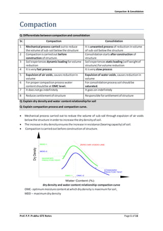
  • 1. Compaction & Consolidation Prof. P.P. Prabhu-GTE Notes Page 1 of 16 Compaction Q: Differentiate betweencompactionand consolidation Sr. Compaction Consolidation 1 Mechanical process carried outto reduce the volume of sub-soil below the structure It isunwanted processof reductioninvolume of sub-soil below the structure 2 Compactioniscarriedout before construction of structure. Consolidationstarts afterconstruction of structure 3 Soil experiences dynamicloadingforvolume reduction Soil experiences staticloading(self weightof structure) forvolume reduction 4 It isvery fast process It isvery slow process 5 Expulsionof air voids,causesreductionin volume Expulsionof water voids,causesreductionin volume 6 For propercompactionprocesswater contentshouldbe at OMC level. For consolidationprocesssoil shouldbe saturated. 7 It doesnotgo indefinitely It goeson indefinitely 8 Reducessettlementof structure Responsible forsettlementof structure Q: Explain dry densityand water contentrelationshipfor soil Q: Explain compaction processand compaction curve.  Mechanical process carried out to reduce the volume of sub-soil through expulsion of air voids belowthe structure inorderto increase the drydensityof soil.  The increase indry densityensuresthe increase inresistance (bearingcapacity) of soil.  Compactioniscarriedout before constructionof structure. dry density and water content relationship-compaction curve OMC- optimummoisture contentatwhichdrydensityis maximumforsoil, MDD – maximumdrydensity ZERO AIR VOIDS LINE MODIFIED PROCTOR TEST STANDARD PROCTOR TEST MDD-1 MDD-2 OMC-1 OMC-2 Water Content (%) DryDensity
  • 2. Compaction & Consolidation Prof. P.P. Prabhu-GTE Notes Page 2 of 16  Explanation ofgraph: o Optimum Moisture Content (OMC) is the moisture content at which the maximum possible dry density is achieved for a particular compaction energy or compaction method. o The correspondingdrydensityiscalledMaximumDryDensity(MDD). o Water is added to lubricate the contact surfaces of soil particles and improve the compressibilityof the soil matrix. o It should be noted that increase in water content increases the dry density inmost soils up to one stage (Dry side). o Water acts as lubrication. o Beyond this level, any further increase in water (Wet side)will only add more void space, there byreducingthe dry density. o Hence OMC indicatesthe boundarybetweenthe dryside andwetside. o Hence the compaction curve as shown in figure indicates the initial upward trend up to OMC and the downward trend.  Effect of Compaction process: 1) Increases density 2) Increases strength characteristics 3) Increases load-bearing capacity 4) Decreases undesirable settlement 5) Increases stability of slopes and embankments 6) Decreases permeability 7) Reduces water seepage 8) Reduces Swelling & Shrinkage 9) Reduces frost damage 10) Reduces erosion damage 11) Develops high negative pore pressures(suctions) increasingeffective stress Q: Explain Standard Proctor test/ ModifiedProctor test. Q: differentiate between StandardProctor test& ModifiedProctor test. Sr. Standard Proctor Test ModifiedProctor Test 1 Mouldcapacity 1000 cc or 2250 cc Mouldcapacity 1000 cc or 2250 cc 2 Rammerused- 2.6 kg Drop height=31cm Rammerused- 4.89 kg Drop height= 45cm 3 Three layersforsoil compaction Five layersforsoil compaction 4 Numberof blows: If 1000cc mouldused= 25 for eachlayer If 2250cc mouldused= 56 for eachlayer Numberof blows: If 1000cc mouldused= 25 for eachlayer If 2250cc mouldused= 56 for eachlayer 5 MDD islowcomparedto Modifiedtest OMC is highcomparedto Modified test MDD ishighcomparedto Standardtest OMC is low comparedto Standardtest Procedure: 1. About3 kg of dry soil,passingthrough4.75 mm sieve. 2. Addapprox.5-8%of waterfor the firsttrial.(Less -Corse grained&more -Fine grainedsoil) 3. Finddimensionsandweightof mould.Note itdownseparately. 4. The innersurfacesof mould,base plate andcollarare greased.
  • 3. Compaction & Consolidation Prof. P.P. Prabhu-GTE Notes Page 3 of 16 5. Soil isplacedinmouldandcompactedin 3 uniformlayers forSPT/5 layersforMPT , with25 blowsineachlayerof standardrammer(Rammerused- 2.6 kg wt.& dropheight=31cm for SPT/4.89 kg wt. & drop height=45cm for SPT forMPT) 6. Afterfinal layerremove excesssoil/trimtopsurface 7. Weighthe mouldandsoil.Take some sample of soil fordeterminationof watercontent. 8. The procedure isrepeatedwithincreasingwatercontent. 9. The numberof trialsshall be at least6 witha few afterthe decreasingtrendof bulkdensity. 10. Plotthe graph of dry densityvswatercontent. Q: Explain compaction methodsand its suitability  Rammers: o Rammers are used for compacting small areas by providing impact load to the soil. This equipmentislightandcanbe hand or machine operated. o For machine operatedrammers,the usual weightvariesfrom30kgto 10 tonnes. o These hammers with 2- 3 tonnes weights are allowed to free fall from a height of 1m to 2m on the soil for the compactionof rock fragments. o Rammersare suitable forcompacting cohesive soilsaswell asothersoils. o Thismachine usedinareaswithdifficultyinaccess.  VibratingPlate Compactors: o Vibratingplate compactorsare usedforcompactionof coarse soils o These equipmentsare usedforsmall areas.  Vibro Tampers: o Vibrotampersisusedforcompactionof small areas inconfinedspace. o Thismachine issuitable forcompactionof all typesof soil by  Smooth WheeledRollers: o Smooth wheeled rollers are of two types: Static smooth wheeled rollers & Vibrating smoothwheeledrollers o The most suitable soils for these roller type are well graded sand, gravel, crushed rock, asphaltetc.where crushingisrequired. o These are usedon soilswhichdoesnotrequire greatpressure forcompaction. ZERO AIR VOIDS LINE MODIFIED PROCTOR TEST STANDARD PROCTOR TEST MDD-1 MDD-2 OMC-1 OMC-2 Water Content (%) DryDensity
  • 4. Compaction & Consolidation Prof. P.P. Prabhu-GTE Notes Page 4 of 16 o These rollersare generallyusedforfinishingthe uppersurface of the soil. o These rollerare notusedfor compactionof uniformsands. o The performance of smooth wheeled rollers depend on load per cm width it transfers to the soil and diameterof the drum. o The smooth wheeled rollers consists of one large steel drum in front and two steel drumson the rear. The gross weightof these rollers isinthe range of 8-10 tonnes. o The other type of smooth wheel roller is called Tandem Roller, which weighs between 6- 8 tonne. o The performance of these rollers can be increased by increasing the increasing the weightof the drumby ballastingthe insideof drumswithwetsandor water. o In case of vibrating smoothwheeled rollers, the drums are made to vibrate by employing rotatingor reciprocatingmass. o These rollers are helpful from several considerations like:- (i) Higher compaction level can be achieved with maximum work (ii) Compaction can be done up to greater depths (iii) Outputismanytimesmore thanconventional rollers o Although these rollers are expensive but in the long term the cost becomes economical due to theirhigheroutputsandimprovedperformance. o The latest work specifications for excavation recommends the use of vibratory rollers due to theiradvantage overstaticsmoothwheeledrollers.  SheepsfootrollerRoller: o Sheepsfoot rollers are used for compacting fine grained soils such as heavy clays and siltyclays. o Sheepsfoot rollers are used for compaction of soils in dams, embankments, subgrade layersin pavementsandrail roadconstructionprojects. o Sheepsfootrollersare of staticandvibratorytypes. o Vibratory types rollers are used for compaction of all fine grained soils and also soil with sand-gravel mixes. o Generallythisrollerisusedforcompactionof subgrade layersinroadand rail projects. o The weight of drums can be increased as in the case of smooth wheeled rollers by ballastingwithwater,wetsandorbymountingsteel sections. o The efficiency of sheepsfoot rollers compaction can be achieved when lugs are gradual walkout of the roller lugs with successive coverage. The efficiency is affected by the pressure on the foot and coverage of ground obtained per pass. For required pressure and coverage of ground, the parameters such as gross weight of the roller, the area of each foot, the number of lugs in contact with the ground at any time and total number of feetperdrumare considered. o The compaction of soil is mainly due to foots penetrating and exerting pressure on the soil.The pressure ismaximumwhenafootisvertical.  PneumaticTyred Rollers: o Pneumatictyredrollersare alsocalledasrubbertyredrollers. o These rollersare usedforcompactionof coarse grainedsoilswithsome fines. o These rollersare leastsuitableforuniformcoarse soilsandrocks. o Generally pneumatic tyred rollers are used in pavement subgrade works both earthwork and bituminousworks.
  • 5. Compaction & Consolidation Prof. P.P. Prabhu-GTE Notes Page 5 of 16 o Pneumatic rollers have wheels on both axles. These wheels are staggered for compactionof soil layerswithuniformpressurethroughout the widthof the roller. o The factor which affects the degree of compaction is tyre inflation pressure and the area of the contact.  GridRollers: o Grid rollersare usedforcompactionof weatheredrocks,well gradedcoarse soils. o These rollersare notsuitable forclayeysoils,siltyclaysanduniformsoils. o The main use of these rollersare insubgrade andsub-base inroadconstructions. o As the name suggests, these rollers have a cylindrical heavy steel surface consisting of a networkof steel barsformingagrid withsquire holes. o The weightof thisrollercan be increasedbyballastingwithconcrete blocks. o Typical weightsvarybetween5.5tonnesnetand 15 tonnesballasted. o Grid rollers provide high contact pressure but little kneading action and are suitable for compactingmostcoarse grainedsoils.  Pad Foot / Tamping Rollers: o These rollers are similar to sheep foot rollers with lugs of larger area than sheep foot rollers. o The static pad foot rollers also called tamping rollers have static weights in the range of 15 to 40 tonnesand theirstaticlineardrumloadsare between30and 80 kg/cm. o These rollers are more preferable than sheep foot roller due to their high production capacity,and theyare replacing sheepfootrollers. o The degree of compactionachievedismore than sheepfootrollers. o The densityof soil achievedaftercompactionwiththisrollerismore uniform. o These rollersoperate athighspeeds,andare capable tobreakinglarge lumps. o These rollersalsoconsistsof levelingbladestospreadthe material. o Pad footor tampingrollersare bestsuitable forcompactingcohesive soils. Q: Explain compaction Fieldcontrol of compaction methodsand its suitability Q: Explain fieldcompactioncontrol Objective ofFieldCompactionControl: The followingare the importantobjectivesof fieldcompactioncontrol: 1. To determine the in-situdrydensityandwatercontentimmediatelyafterthe compaction 2. To check and ensure that the soils from the prescribed borrow area, having the desired properties,are usedforcompaction. 3. To check and ensure that the required compaction energy is used in compacting the soil. This consists of ensuring that the required type of roller suitable to the soils being compacted is used as well asthat the rollerisof requiredcapacity. 4. Certainminimumnumberof testsare to be done inthe fieldwhenthe compactionisinprogress Determination of In-SituDensity: The determinationof relative compaction requiresthe followingfinding:  In-situbulk density.  Field moisture content. The in-situ density can be computed by following methods:  Core cutter method.  Sand replacementmethod.
  • 6. Compaction & Consolidation Prof. P.P. Prabhu-GTE Notes Page 6 of 16  Rubberballoon method. Determination of watercontentof compacted soilcan bedoneby following methods:  Calciumcarbide method  Proctor’s Needle Method:  NuclearMethod Proctor Needle Test Principle: The basic principle of Proctor’s needle method is to determine the water content of compacted soil indirectly without drying the sample based on the resistance offered by the compactedsoil tothe penetration of Proctor’s needle. About Test:  The Proctor’s needle consists of a needle attached to a spring- loaded plunger.  The needle consists of a needle point attached to the bottom of a needle shank, asshown inFig.  The needle can be pushed into the compacted soil by pressing the loadingplunger.  The needle shank has graduations to read the penetration of the needle intothe compactedsoil.  The stem of the loading plunger has graduations to show the resistance offered by the compacted soil to the penetration of the needle.  The loading plunger is calibrated to indicate the penetration resistance of the compacted soil based on the deformation of the spring, whichdepends onthe loadappliedandthe springconstant.  Needle points of different cross-sectional areas are supplied along with the equipment such as 0.25, 0.5, 1.0, and 2.5 cm2 to use in compacted soilsof increasingpenetration resistance. Determinationof In-SituMoisture Contentand Dry Density:  The soil used for compaction in the field, mixed with placement water content, is compacted into the compaction mouldusingthe same compaction energy.  The Proctor’s needle with the same needle point as used for preparation of calibration chart is forced intothe compactedsoil inthe mouldand the penetration resistance isdetermined.  The water content and dry density of the compacted soil are then read from the calibration chart correspondingtothe penetration resistance.
  • 7. Compaction & Consolidation Prof. P.P. Prabhu-GTE Notes Page 7 of 16 Consolidation Q: Explain Terzaghi’sspring-massanalogy Q: Explain Terzaghi’sconsolidationtheory  Consolidation is process of reduction in volume due to expulsion of water particle with the application of static load for long duration Terzaghi’sSpring Mass Analogy Assumptions:  The soil mediumiscompletelysaturated  The soil mediumisisotropicandhomogeneous  Darcy’s lawisvalidforflowof water  Flowisone dimensionalinthe vertical direction  The coefficientof permeabilityisconstant  The coefficientof volumecompressibilityisconstant  The increase instresson the compressiblesoil depositisconstant(∆σ´= constant)  Soil particlesandwaterare incompressible One dimensional theoryisbasedonthe followinghypothesis 1. The change in volume of soil isequal tovolume of pore waterexpelled. 2. The volume of pore waterexpelledisequal tochange involume of voids. 3. Since compressionisinone directionthe change involume isequal tochange inheight.  T=0  σ = u and σ´=0  Soil=Spring  Water= Water Void  After application of load - primaryconsolidationStart  No reductioninvolume  0<T<∞  σ = u + σ´  All loadisresistedbywater  flow is upward  reductioninvolume  spring& watershare load  T = ∞  All the load is resisted by spring  Water doesn’tcarry any load  Soil solids carry external pressure  Excess pore water pressure is zero  End of primary consolidation
  • 8. Compaction & Consolidation Prof. P.P. Prabhu-GTE Notes Page 8 of 16 Theory  Terzaghi’smodel consistsof avessel withapistonattachedtospringas shown.  The space below piston is filled with water. The piston has outlet to allow for passage of water.  Piezometerscanbe insertedtomeasure the excesspore water pressure.  Terzaghi has correlated the spring mass compression process with the consolidation of saturatedclaysubjectedtoexternal loadσ.  The springs and the surroundingwaterrepresentthe saturatedsoil.  The springs represent the soil skeleton networks of soil grains and water in the vessels representsthe waterinthe voids.  In this arrangement the compression is one dimensional and flow will be in the vertical direction.  Whenpressure σis appliedthiswill be borne bywatersurroundingthe spring σ = u and σ´=0 at time t =0 where,uiscalledexcesshydrostaticpressure andthere willbe novolume change.  Aftersometime ‘t’there will be flow of waterthrough outlet.  Since the flowisinupwarddirection/segmentthere will be reductioninvolume.  Due to thisspringget compressedandbeingtocarry a portionof the applied load.  Thissignifiesareduction inexcesspore waterpressure andincrease ineffectivestress. σ = u + σ´ load shared by both water and spring  At time t = ∞ when no more pore water flows out the excess hydrostatic pressure will be and the entire loadiscarriedbyspring. σ = σ’ and u=0 at time t =∞ Q: Explain laboratory consolidationtest The test isconductedto determinethe settlementdue toprimaryconsolidation.Todetermine:  Rate of consolidationundernormal load.  Degree of consolidationatanytime.  Pressure-voidratiorelationship.  Coefficientof consolidationatvariouspressures.  Compressionindex. From the above information it will be possible for us to predict the time rate and extent of settlement of structuresfounded on fine-grained soils. It is also helpful in analyzing the stress history of soil. Since the settlement analysis of the foundation depends mainly on the values determined by the test,thistestis veryimportantforfoundationdesign. Principal Involved
  • 9. Compaction & Consolidation Prof. P.P. Prabhu-GTE Notes Page 9 of 16 When a compressive load is applied to soil mass, a decrease in its volume takes place, the decrease in volume of soil mass under stress is known as compression and the property of soil mass pertaining to its tendency to decrease in volume under pressure is known as compressibility. In a saturated soil mass having its void filled with incompressible water, decrease in volume or compression can take place when water is expelled out of the voids. Such a compression resulting froma longtime staticloadand the consequentescape of pore wateristermedasconsolidation. Procedure 1] Saturate two porous stones by keeping them submerged in the distilled water for 4 to 8 hrs. Wipe awayexcesswater. 2] Assemble the consolidometer, with the soil specimen and porous stones at top and bottom of specimen, providing a filter paper between the soil specimen and porous stone. Position the pressure padcentrallyonthe topporous stone. 3] Mount the mould assembly on the loading frame, and center it such that the load applied is axial. 4] Position the dial gauge to measure the vertical compression of the specimen. The dial gauge holder should be set so that the dial gauge is in the begging of its releases run, allowing sufficientmarginforthe swellingof the soil,if any. 5] Connect the mould assembly to the water reservoir and the sample is allowed to saturate. The level of the waterinthe reservoirshouldbe ataboutthe same level asthe soil specimen. 6] Apply an initial load to the assembly. The magnitude of this load should be chosen by trial, such that there isno swelling. 7] The load should be allowed to stand until there is no change in dial gauge readings for two consecutive hoursorfora maximumof 24 hours. 8] Note the final dial reading under the initial load. Apply first load of intensity 0.1 kg/cm2 start the stop watch simultaneously. Record the dial gauge readings at various time intervals. The dial gauge readings are taken until 90% consolidation is reached. Primary consolidation is gradually reachedwithin24 hrs. 9] At the end of the period, specified above take the dial reading and time reading. Double the load intensity and take the dial readings at various time intervals. Repeat this procedure for successive loadincrements.The usual loadingintensityare asfollows: a. 0.1, 0.2, 0.5, 1, 2, 4 and 8 kg/cm2. 10] After the last loadingis completed, reduce the load to half of the value of the last load and allow it to stand for 24 hrs. Reduce the load further in steps of half the previous intensity till an intensityof 0.1kg/cm2 is reached.Take the final reading of the dial gauge. 11] Reduce the load to the initial load, keep it for 24 hrs and note the final readings of the dial gauge. 12] Quickly dismantle the specimen assembly and remove the excess water on the soil specimen in oven,note the dryweightof it. Analysis: (1) Calculate the initial watercontentandspecificgravityof the soil. (2) For each pressure increment, construct a semi-log plot of the consolidation dial readings versus the log time (inminutes). Determine the coefficientof consolidation (cv). (3) Calculate the void ratio at the end of primary consolidation for each pressure increment. Plotlog pressure versus void ratio. Based on this plot, calculate compression index, recompression index and preconsolidation pressure (maximumpastpressure).
  • 10. Compaction & Consolidation Prof. P.P. Prabhu-GTE Notes Page 10 of 16 Q: Explain Log – time curve fittingmethod to findcoefficientofconsolidation(Cv) The basis for this method is the theoretical (Uz ) versus log Tv curve and experimental dial gauge readingandlog(t) curvesare similar. Steps i. Plot the dial reading of compression for a given pressure increment versus time to log scale as showninfigure. ii. Plot two points P and Q on the upper portion of the consolidation curve (say compression line) correspondingtotime t1 and t2 suchthat t2 =4t 1 iii. Let x be the difference in dial reading between P and Q. locate R at a vertical distance x above pointP iv. Draw a horizontal line RS the dial reading corresponding to this line is d 0 which corresponds with0% consolidation. v. Project the straight line portion of primary and secondary consolidation to intersect at point T. The dial readingcorrespondingtoT isd 100 andthiscorrespondsto 100% consolidation. vi. Determine the pointV onthe consolidationcurve whichcorrespondstothe dial readingof d50 = (d0 +d100)/2. The time correspondingtopointV ist 50 i.e time for50% consolidation. Log – time curve fitting method
  • 11. Compaction & Consolidation Prof. P.P. Prabhu-GTE Notes Page 11 of 16 Q: Explain Square root of time method to findcoefficientofconsolidation(Cv) i. Plotthe dial readingandthe correspondingsquare-root-of-time 𝑡asshownin Figure ii. Draw the tangentPQ to the earlyportionof the plot. iii. Draw a line PRsuch that OR = (1.15)(OQ). iv. The abscissaof the pointS (i.e.,the intersectionof PRand the consolidationcurve) will give √𝑡90 ( i.e.,the square-root-of-timefor90% consolidation). v. The value of 𝑇 𝑣 for Uav = 90% 𝑖𝑠 0.848. so, Square root of time method Q: Explain soil compressibilitycharacteristics Q: Explain normallyconsolidated,over and under consolidatedsoil  A laboratory soil specimen of dia 60mm and height 20mm is extracted from the undisturbed soil sample obtainedfromthe field.  Thissample issubjectedto1D consolidationinthe ladundervariouspressureincrements.  Each pressure increment is maintained for 24 hrs and equilibrium void ratio is recorded before the applicationof the nextpressure increment.  Thena plotof voidratioversuseffectivestressismade asshowninFig.  When the sample is recompressed from point D it follows DE and beyond C it merges along BCF and itcompressesasit movesalongBCF  During the initial stages (at low effective stress) sample follows recompression path (portion AB) and undergoeslesscompression.  Beyond this is the virgin compression line (portion BC) also called the normal compression line and the sample undergoeslarge compression. 1. BC – Virgincompressioncurve alsocalled normal consolidationline
  • 12. Compaction & Consolidation Prof. P.P. Prabhu-GTE Notes Page 12 of 16 2. From ‘C’ when the sample is unloaded, sample expands and traces path CD (expansion curve unloading) 3. Sample undergoes Permanent strain due to irreversible soil structure and there is a small elastic recovery. 4. The deformationrecoveredisdue to elasticrebound 5. When the sample is reloaded-reloading curve lies above the rebound curve and makes an hysteresisloopbetweenexpansionandreloadingcurves. 6. The reloadedsoilsshowslesscompression. 7. Loading beyond ‘C’ makes the curve to merge smoothly into portion EF as if the soil is not unloaded. Soil Compressibility
  • 13. Compaction & Consolidation Prof. P.P. Prabhu-GTE Notes Page 13 of 16 It is the maximum effective stress experienced by a soil in its stress history (past existence)  For the soil loaded along the recompression curve AB the effective stress close to point B will be the preconsolidationpressure.  If the soil is compressed along BC and unloaded along CD and then reloaded along DC the effectivestressclose topointCwill be the new preconsolidationpressure. Effectof Stress History It isbasedon the stresshistory(preconsolidationpressure)soilsare classifiedas 1. NormallyConsolidatedSoils 2. Over ConsolidatedSoils 3. Under ConsolidatedSoils Normally Consolidated Soils It is a soil deposit that has never subjected to a vertical effective stress greaterthan the presentvertical stress. Under Consolidated Soils A soil deposit that has not consolidated under the present overburden pressure (effective stress) is called Under Consolidated Soil. These soils are susceptible to larger deformationandcause distressinbuildingsbuiltonthese deposits.
  • 14. Compaction & Consolidation Prof. P.P. Prabhu-GTE Notes Page 14 of 16 Over Consolidated Soils Itis a soil deposit that has been subjected to vertical effective stress greater than the presentvertical effective stress. Q: how to determine pre-consolidationpressure ? Determinationof PreconsolidationPressure (YieldStress) Step1. Conductan oedometertestonthe undisturbedsoil sampleobtainedfromthe field. Step2. Plot e - log σ´ plot as shown. The equilibrium void ratio at the end of each of the pressure incrementsare usedinobtaininge - logσ´ plot. Step3. Selectthe pointof maximumcurvature (PointA) onthe e - log σ´ curve Step4. Draw a tangentat the pointof maximum curvature (PointA) Step5. Draw a horizontal line AC Step6. Draw the bisectorline ADbetweenthe tangentandhorizontal line Step7. Extendthe normallyconsolidatedline tointersectthe bisectorlineat ‘O’ Step8. The vertical effective stress corresponding to point of intersection (O) is the preconsolidationpressure (σ´pc) Q: Explain compressibilitycharacteristicsmv, av,Cc Compressibility Characteristics The compressibility of soils under one-dimensional compression can be described from the decrease in the volume of voids with the increase of effective stress. This relation of void ratio and effective stresscan be depictedeitherasan arithmetic plotor a semi-logplot. It can be said that the compressibility of a soil decreases as the effective stress increases. This can be represented by the slope of the void ratio – effective stress relation, which is called the coefficientofcompressibility,av. 𝑎 𝑣 = 𝑒1 − 𝑒2 𝜎2 ′ − 𝜎1 ′ O
  • 15. Compaction & Consolidation Prof. P.P. Prabhu-GTE Notes Page 15 of 16 Co-efficient of volume compressibility (mv) It is the ratio of change in volume of a soil per unitinitial volume due tounitincrease ineffective stressandisgivenby 𝑚 𝑣 = 𝑎 𝑣 1+ 𝑒 𝑜 Coefficient of compression/compression index (Cc):It is the slope of the normal consolidationline in a plotof voidratio-logarithmof effectivestress(e - logσ´).Itisgivenby Empirical correlations Cc = 0.009 (LL-10) Undisturbedclays Cc = 0.007 (LL-10) Remouldedsoil sample Cc = 1.15 (e0-0.30) Upperboundvalues Cc = 0.30 (e0-0.27) Lowerboundvalues The value of Cc is constant for a given soil. The compression index is used to determine primary consolidation settlement of normally consolidated soils. A high value of Cc indicates high compressibilityandhigherconsolidationsettlement.
  • 16. Compaction & Consolidation Prof. P.P. Prabhu-GTE Notes Page 16 of 16 Formulae in Consolidation chapter:  Compressionindex  It isa slope of pressure-voidsratiocurve whenplottedonlogarithmicgraph  𝑐 𝑐 = 𝑒0− 𝑒 log10( 𝜎′ 𝜎0 ′ )  Coefficientofcompressibility  It isa slope of pressure-voidsratiocurve whenplottedonnatural graph  𝑎 𝑣 = 𝑒0− 𝑒 𝜎′− 𝜎0 ′  Coefficientofvolume change  𝑚 𝑣 = 𝑎 𝑣 1 + 𝑒0  Where,e0 isinitial voidsratioswhenpressure = 𝜎0 ′, e is voidsratiowhenpressure change to 𝜎′  Consolidationsettlement  𝜌𝑓 = 𝑚 𝑣 𝐻 ∆𝜎′  H = soil thickness, ∆𝜎′=pressure increment  CoefficientofConsolidation  𝑐 𝑣 = 𝑘 𝑚 𝑣 𝛾 𝑤  Where,kis coefficientof permeability  From consolidationtestdata o 𝑐 𝑣 = 𝑇𝑣 𝑡 𝑑2 o 𝑇𝑣 = 𝜋 4 ( 𝑈 100 ) 2 ….whendegree of consolidation=U < 60% o 𝑇𝑣 = −0.9332 log10 (1 − 𝑈 100 ) − 0.0851….whendegree of consolidation=U > 60% o Where,Tv is time factor, t is time requiredforconsolidation,disdrainage path o d = soil thicknesswhensoil hassingledrainage o d = (soil thickness/2) whensoil hasdouble drainage