Rcc member design steps
•
9 likes•3,312 views

RCC member/structure design steps in detail w.r.t. IS code references

Recommended
Recommended
More Related Content
What's hot
What's hot (20)
Similar to Rcc member design steps
Similar to Rcc member design steps (20)
More from DYPCET
More from DYPCET (17)
Recently uploaded
Recently uploaded (20)
Rcc member design steps
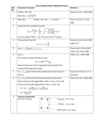
- 1. Unit 1- Design of Beam subjected to Torsion Step No. Calculation / Procedure Reference 1 Find Me1 = Mu + Mt Where 𝑀 = 𝑇 ⁄ . Clause no 41.4.2, IS 456: 2000 2 If Mt > Mu, Find Me2 = Mt – Mu…….. if required Clause no 41.4.2.1, IS 456: 2000 3 Find Ast for Me1 and Me2(if required) 𝐴 = 0.5 𝑓 𝑓 × 1 − 1 − 4.6 𝑀 𝑓 𝑏 𝑑 × 𝑏 𝑑 Me1 Ast1 (bottom steel) Me2 Ast2 (top steel) * if required 4 Find Equivalent Shear=Ve 𝑉 = 𝑉 + 1.6 𝑇 𝑏 Clause no 41.3.1, IS 456: 2000, page no 75 5 Find 𝜏 = Check 𝜏 ≤ 𝜏 Clause no 40.1, IS 456: 2000 Table no.20 , IS 456: 2000 6 Find 𝜏 If % of steel is not given find Pt% as under 𝑃 % = 100 × 𝐴 𝑏𝑑 Where Ast tension steel or longitudinal steel calculated from maximum BM subjected to torsion Table no.19 , IS 456: 2000 7 If 𝜏 > 𝜏 go for minimum shear reinforcement as per clause no. 26.5.1.6 Clause no 40.4 & 26.5.1.6, IS 456: 2000 8 If 𝜏 < 𝜏 find Sv from (a) & (b) and provide minimum value If Assumed stirrups2 legged #8mm Asv = 2 x Aᵩ = 2x 50 =100 If Assumed stirrups2 legged #10mm Asv = 2 x 78 = 156 a) 𝐴 = . + . . b) ( ) . Clause no 41.4.3, IS 456: 2000 9 Summary and detailing: Ast1, Ast2 , Stirrups Top steel Bottom steel Stirrups (As per design) (As per design) (As per design)
- 2. Unit-2- Continuous Beams Steps Calculations/ procedure Reference 1 Cross sectional Dimensions Effective depth = 𝑑 . = Adopt, effective cover= dc = 50mm Thus, D= dc + deffe width of beam = width of wall (generally 230, 300 etc.) 2 Loads Dead Load (a) Self weight of beam = b x D x 25 (b) DL on beam = (given in kN/m) Total DL = g = (a) + (b) Live Load = q = (given in kN/m) ***Ultimate loads Dead load = gu = 1.5 x g Live load = qu = 1.5 x q 3 Design Bending Moment and Shear Force Maximum -ve BM at interior supports 𝑀 = 𝑐𝑜𝑒𝑓𝑓𝑖𝑐𝑖𝑒𝑛𝑡 × 𝑔 × 𝐿 + 𝑐𝑜𝑒𝑓𝑓𝑖𝑐𝑖𝑒𝑛𝑡 × 𝑞 × 𝐿 Maximum +ve BM at Center of span 𝑀 = 𝑐𝑜𝑒𝑓𝑓𝑖𝑐𝑖𝑒𝑛𝑡 × 𝑔 × 𝐿 + 𝑐𝑜𝑒𝑓𝑓𝑖𝑐𝑖𝑒𝑛𝑡 × 𝑞 × 𝐿 Maximum Shear at support (next to end) 𝑉 = 𝑐𝑜𝑒𝑓𝑓𝑖𝑐𝑖𝑒𝑛𝑡 × 𝑔 × 𝐿 + 𝑐𝑜𝑒𝑓𝑓𝑖𝑐𝑖𝑒𝑛𝑡 × 𝑞 × 𝐿 Table no. 12 and 13 of IS 456:2000, pp36 C1, C2, C3 column of respective table 4 Reinforcement Find Steel for M-ve and M+ve 𝐴 = . 1 − 1 − . 𝑏𝑑 Select diameter (Ф), find area (A Ф) and number of bars No. of bars= . Dia. (Ф) 8 10 12 16 20 25 Area (A Ф) 50 78 113 201 314 490 5 Shear reinforcement Find 𝜏 = Check 𝜏 ≤ 𝜏 Clause no 40.1, IS 456: 2000 Table no.20 , IS 456: 2000 Find 𝜏 If % of steel is not given find Pt% as under Table no.19 , IS 456: 2000 C 1 C 2 C 3 C 4 C 4 C 3 C 2 C 1 C 1 C 2 C 2 C 1 C 3 C 4 C 3 B M C O E F F IC IE N T (C O L U M N N O . IN T A B L E 1 2 ) S F C O E F F IC IE N T (C O L U M N N O . IN T A B L E 1 3 )
- 3. 𝑃 % = 100 × 𝐴 𝑏𝑑 Where Ast tension steel or longitudinal steel calculated from maximum BM subjected to torsion If 𝜏 > 𝜏 go for minimum shear reinforcement as per clause no. 26.5.1.6 Clause no 40.4 & 26.5.1.6, IS 456: 2000 If 𝜏 < 𝜏 find Sv from 𝑉 = 𝑉 − 𝜏 𝑏 d If Assumed stirrups2 legged #8mm Asv = 2 x Aᵩ = 2x 50 =100 If Assumed stirrups2 legged #10mm Asv = 2 x 78 = 156 𝑉 = 0.87 𝑓 𝐴 𝑑 𝑆 Clause no 41.4.3, IS 456: 2000 6 Deflection Control Find & 𝐿 𝑑 = 𝐿 𝑑 × 𝑘 × 𝑘 × 𝑘 < then safe 𝐿 𝑑 = 26 𝑘 = 1 𝑘 = 1 7 Detailing Curtail bars Curtail bars Curtail bars Extra Top Extra Top Top Straight Bars Bottom Straight Bars D L1 L2 L3
- 4. For redistribution of Moments Step no. 3 Changes as below Find Fixed end moment for each beam AB, BC, CD,…. 𝐹𝐸𝑀 = Find Span moments for each beam AB, BC, CD,…. 𝑆𝑝𝑎𝑛 𝑀𝑜𝑚𝑒𝑛𝑡𝑠 = Create table Find Final Span moments and End Moments: Support B C (if required) process Span Moment FEM (average of AB & BC) Span Moment FEM (average of CB & CD) Span Moment X1 X2 X3 X4 X5 R % redistribution -X1 * R/100 -X3 * R/100 -X5 * R/100 -X3 * R/100 Carry over -X3 * R/100*(1/2) -X1 * R/100*(1/2) -X5 * R/100*(1/2) -X3 * R/100*(1/2) Final Moment Sum sum sum sum Sum Span Moment Support Moment Span Moment Support Moment Span Moment
- 5. Unit No.3 - Design of Circular Water Tank Flexible Base / Not casted monolithically /Not restrained at base Step No. Calculation /Procedure Referance 1. Thk of Wall a) 150 mm b) 30mm per m depth + 50 mm Provide greater of a) & b) 2. Hoop Tension 𝑇 = . . where 𝛾 = 9.81𝑘𝑁/𝑚 3. Find Ast required for 1 m ht. 𝐴 = Minimum steel required = 0.3 % of gross area. 4. Select diameter (Ф) of bar and find spacing Dia. (Ф) 8 10 12 16 20 25 Area (A Ф) 50 78 113 201 314 490 Spacing = S = × . ……. Provide spacing less than actual required. Provide this steel near both the face. 5. Actual Ast Provided 𝐴 . = 𝐴 × 1000 𝑆 6. Tensile Stress in Concrete 𝐶 = ( × ) (( ) ) 𝐹𝑜𝑟 𝑀20, 𝐶 = 1.2 𝑁/𝑚𝑚 , b = 1000, 𝐴 = 𝐴 . Table 1, IS 3370 Part 2 , PP.7 7. Vertical Distribution Steel At least 0.3% of gross area. = 0.3 100 × 1000 × 𝑡 Select diameter (Ф) of bar and find spacing 8. Base Slab i) 150 mm thick slab Top mesh and bottom mesh of steel 10 𝑚𝑚 ∅ @ 300 𝑚𝑚 . 9 Detailing See attached
- 6. Rigid Base / casted monolithically / restrained at base Approximate Method Step No. Calculation /Procedure Referance 1. Height of cantilever effect: 𝑜𝑟 1 𝑚 𝑤ℎ𝑖𝑐ℎ𝑒𝑣𝑒𝑟 𝑖𝑠 𝑔𝑟𝑒𝑎𝑡𝑒𝑟 2. Hoop Tension 𝑇 = .( ). where, 𝛾 = 9.81𝑘𝑁/𝑚 3. Find Ast required for 1 m ht. 𝐴 = Minimum steel required = 0.3 % of gross area. 4. Select diameter (Ф) of bar and find spacing Dia. (Ф) 8 10 12 16 20 25 Area (A Ф) 50 78 113 201 314 490 Spacing = S = × . ……. Provide spacing less than actual required. Provide this steel near both the face. 5. Actual Ast Provided, 𝐴 . = × 6. Find thickness of Wall(t) Tensile Stress in Concrete 𝐶 = ( × ) (( ) ) 𝐹𝑜𝑟 𝑀20, 𝐶 = 1.2 𝑁/𝑚𝑚 , b = 1000, 𝐴 = 𝐴 . Table 1, IS 3370 Part 2 , PP.7 7. Vertical Distribution Steel At least 0.3% of gross area. = 0.3 100 × 1000 × 𝑡 Select diameter (Ф) of bar and find spacing 8. Design of Bottom cantilever part ( For h ) Max. moment due to cantilever effect 𝑀 = ( × 𝑏 × ℎ) × Where, b = (𝛾 × 𝐻) 9. Area of Steel 𝐴 𝑀 𝜎 × 𝑗 × 𝑑 𝜎 − 𝐹𝑟𝑜𝑚 𝑇𝑎𝑏𝑙𝑒 2 𝑃𝑃. 8 𝜎 = 115 𝐹𝑜𝑟 𝐹𝑒 − 250 𝜎 = 150 𝐹𝑜𝑟 𝐹𝑒 − 415 𝜎 = 205 𝐹𝑜𝑟 𝐹𝑒 − 500 10. Haunch Reinforcement Haunch Reinforcement= Min. steel= (0.3% × 𝑏 × 𝑑) 11. Base Slab i) 150 mm thick slab Top mesh and bottom mesh of steel 10 𝑚𝑚 ∅ @ 300 𝑚𝑚 . 12 Detailing See attached
- 7. Rigid Base / casted monolithically / restrained at base I S code Method Step No. Calculation /Procedure Referance 1. Thk. Of wall (i) 150mm (ii) 30mm per M depth +50mm Find 𝐻 𝐷𝑡 2. Hoop Tension 𝑇 = .( ). where, 𝛾 = 9.81𝑘𝑁/𝑚 3. Find Ast required for 1 m ht. 𝐴 = Minimum steel required = 0.3 % of gross area. 4. Select diameter (Ф) of bar and find spacing Dia. (Ф) 8 10 12 16 20 25 Area (A Ф) 50 78 113 201 314 490 Spacing = S = × . ……. Provide spacing less than actual required. Provide this steel near both the face. 5. Actual Ast Provided 𝐴 . = × 6. Find thickness of Wall(t) Tensile Stress in Concrete 𝐶 = ( × ) (( ) ) 𝐹𝑜𝑟 𝑀20, 𝐶 = 1.2 𝑁/𝑚𝑚 , b = 1000, 𝐴 = 𝐴 . Table 1, IS 3370 Part 2 , PP.7 7. Vertical Distribution Steel: At least 0.3% of gross area = . × 1000 × 𝑡 Select diameter (Ф) of bar and find spacing 8. Design of Bottom cantilever part ( For h ) Max. moment due to cantilever effect = 𝑀 = ( × 𝑏 × ℎ) × Where, b = (𝛾 × 𝐻) 9. Area of Steel, 𝐴 × × 𝜎 = 115 𝐹𝑜𝑟 𝐹𝑒 − 250, 𝜎 = 150 𝐹𝑜𝑟 𝐹𝑒 − 415, 𝜎 = 205 𝐹𝑜𝑟 𝐹𝑒 − 500 𝜎 − 𝐹𝑟𝑜𝑚 𝑇𝑎𝑏𝑙𝑒 2 𝑃𝑃. 8 10. Distribution Steel, = × (0.3% × 𝑏 × 𝑑) b=1000 , d=effective depth 11. Base Slab, = 150 mm thk Top mesh and bottom mesh of steel 10 𝑚𝑚 ∅ @ 300 𝑚𝑚 . 12 Detailing See attached
- 8. t H h # -(dia)- mm@ -(spacing)- c/c Hoop Tension Steel (refer step no. 4) # -(dia)- mm@ -(spacing)- c/c Distribution Steel (refer step no. 7) Horizontal Steel Vertical Steel # -(dia)- mm@ -(spacing)- c/c (refer step no. 8) Base slab steel thk. of base slab Detailing of circular water tank with flexible base t H h # -(dia)- mm@ -(spacing)- c/c Hoop Tension Steel (refer step no. 4) # -(dia)- mm@ -(spacing)- c/c Distribution Steel (refer step no. 7) Horizontal Steel Vertical Steel # -(dia)- mm@ -(spacing)- c/c (refer step no. 11) Base slab steel thk. of base slab Detailing of circular water tank with rigid base # -(dia)- mm@ -(spacing)- c/c Haunch Reinforcement (refer step no. 10) # -(dia)- mm@ -(spacing)- c/c Cantilever BM Steel (refer step no. 9) Vertical Steel
- 9. Design of Rectangular or Square Water Tank Step No. Calculation /Procedure 1 Design constants 𝜎 − 𝑓𝑟𝑜𝑚 𝑡𝑎𝑏𝑙𝑒 𝑛𝑜. 21 𝐼𝑆 456: 2000 𝜎 − 𝐼𝑆 3370 𝑃𝑎𝑟𝑡 𝐼𝐼 for Fe250=115, Fe415=150, Fe500=205 𝑚 = 280/(3𝜎 ), 𝑛 = , 𝑗 = 1 − (𝑛/3) 2. Thk. Of wall (i) 150mm (ii) 30mm per M depth +50mm (iii) 60mmper meter length of side Provide maximum of (i) to (iii) 3 Design of Short wall (a) Mid span section: 𝑇 = .( ). where L-length of longer wall 𝑀 = .( ). 𝟏𝟔 where l-length of short wall 𝑁𝑒𝑡 𝐵𝑀 = 𝑀 − 𝑇𝑥 where x = (t/2)-cover Steel for net BM 𝐴 × × Steel for pull 𝐴 Total Steel = 𝐴 = 𝐴 + 𝐴 (b) Corner section: 𝑇 = .( ). where L-length of longer wall 𝑀 = .( ). 𝟏𝟐 where l-length of short wall 𝑁𝑒𝑡 𝐵𝑀 = 𝑀 − 𝑇𝑥 where x = (t/2)-cover Steel for net BM 𝐴 × × Steel for pull 𝐴 Total Steel = 𝐴 = 𝐴 + 𝐴 4 Design of Long wall (c) Mid span section: 𝑇 = .( ). where l-length of short wall 𝑀 = .( ). 𝟏𝟔 where L-length of long wall 𝑁𝑒𝑡 𝐵𝑀 = 𝑀 − 𝑇𝑥 where x = (t/2)-cover Steel for net BM 𝐴 × × Steel for pull 𝐴 Total Steel = 𝐴 = 𝐴 + 𝐴 (d) Corner section: 𝑇 = .( ). where l -length of short wall 𝑀 = .( ). 𝟏𝟐 where L-length of long wall 𝑁𝑒𝑡 𝐵𝑀 = 𝑀 − 𝑇𝑥 where x = (t/2)-cover Steel for net BM 𝐴 × ×
- 10. Steel for pull 𝐴 Total Steel = 𝐴 = 𝐴 + 𝐴 5 Design of Vertical Steel in both wall Max. moment (cantilever effect) = 𝑀 = ( × 𝛾 × 𝐻 × ℎ) × 𝐴 = 𝑀 𝜎 × 𝑗 × 𝑑 Minimum steel required = 0.3 % of gross area. Ast > Astmin 6 Base Slab, = 200 mm thk Top mesh and bottom mesh of steel 12 𝑚𝑚 ∅ @ 300 𝑚𝑚 . 7 Detailing See attached l L L1 L1 L2 L2 S1S2 S1S2 PLAN
- 11. t H h Distribution Steel Horizontal Steel Vertical Steel Base slab steel thk. of base slab SECTION "L1-L1" Cantilever BM Steel Vertical Steel SECTION "S1-S1" LONG WALL SHORT WALL Inner Face of wall * * * * change steel in above case as per wall t H h Distribution Steel Horizontal Steel Vertical Steel Base slab steel thk. of base slab Cantilever BM Steel Vertical Steel SECTION "L2-L2" SECTION "S2-S2" LONG WALL SHORT WALL Outer face of wall * change steel in above case as per wall * * *
- 12. Unit No.4 - Analysis of Prestress. Cases/ Cable Profiles Calculation / Procedure 1. Tendon placed concentric Stress at top edge = + Stress at bottom edge = − 2. Tendon placed at an eccentricity Stress at top edge = + − . Stress at bottom edge = − + . Where 𝑀 = at mid span (where, w = DL udl + LL udl) 𝑀 = 0 at end section 3. Prestress with Bent Tendon Stress at top edge = + Stress at bottom edge = − Where 𝑀 = ( ). + W- Point load at center w = DL udl + LL udl 4. Prestress with Parabolic Tendon Stress at top edge = + Stress at bottom edge = − Where 𝑀 = and 𝑤 = .
- 13. Unit no. 5.- Losses in Prestress. Cause Calculation / Procedure Pre-tension Post- tension 1. Loss of stress due to elastic shortening of concrete ∆𝑓 = 𝑚. 𝑓 Where – ∆𝑓 = loss of prestress m = modular ratio = 𝑓 = stress in concrete 2. Loss of stress due to creep of concrete ∆𝑓 = ∅ . 𝑚. 𝑓 if ∅ is given in coefficient Or ∆𝑓 = ∅ . 𝑓 . 𝐸 if ∅ is given per 𝑁 𝑚𝑚 3. Loss of stress due to shrinkage of concrete ∆𝑓 = 𝑆ℎ𝑟𝑖𝑛𝑘𝑎𝑔𝑒 𝑠𝑡𝑟𝑎𝑖𝑛 × 𝐸 4. Relaxation Loss 1% to 5 % of initial stress. Or whichever value given in example 5. Loss due to anchorage slip ∆𝑓 = ∆𝛼 . 𝐸 𝐿 Where, ∆𝛼 = effective slip 𝐸 = Young’s modulus for tendon L = Length of Tendon 6. Loss due Friction ( Wobble effect / length effect) 𝑃 = 𝑃 (1 − 𝜇𝛼 − 𝑘𝑥 ) Where - 𝑃 = prestressing force in tendon at any distance x from jack. 𝑃 = prestressing force at jacking end. 𝜇 = co-efficient of friction in curve 0.55-for smooth conc.& 0.30- for steel fixed in duct 𝛼 = cumulative angle in radian 𝑘= friction coefficient (0 to 0.0066 ) ∆𝑓 = 𝑓 . 𝑘. 𝑥 𝑓 = 𝐼𝑛𝑖𝑡𝑖𝑎𝑙 𝑝𝑟𝑒𝑠𝑡𝑟𝑒𝑠𝑠𝑖𝑛𝑔 𝑓𝑜𝑟𝑐𝑒 Total loss of stress ∆𝑓 = ∑(1+2+3+4) ∑ (2+3+4 +5+6) % loss of stress = ∆𝑓 𝐼𝑛𝑖𝑡𝑖𝑎𝑙 𝑆𝑡𝑟𝑒𝑠𝑠 × 100
- 14. Unit no. 6. Design of Pre-stressed member (Beam) Step Procedure (for Rectangular beam section) 1 Calculate live load moment - ML 𝑀 = 𝑤𝑙 8 2 Section Modulus and width of Section: 𝑍 = Choose convenient depth, 𝑑 = × 𝑙 Now find ‘b’ for section using formula, 𝑍 = 3 Prestressing Force: 𝑃 = × 𝐴 4 Steel requirements 𝐴 = select dia. of wire and number of wires 5 Dead load Moment = MD DL= w = b x d x 25 𝑀 = 6 Eccentricity (e) 𝑒 = 2 𝑀 + 𝑀 2 𝑃 7 Drawing: e b d PP L Longitudinal Sectional Elevation Section
- 15. Unit no. 6. Design of Pre-stressed member (Beam) Step Procedure (for Symmetrical I beam section) 1 Safe Stresses Concrete: At transfer, safe compressive stress = fr = 0.5fck At service, safe compressive stress = fc = 0.4fck Permissible tensile stress = ft = 0.129 𝑓 Steel: Safe stress in steel at service = 60% of ultimate stress Ultimate stress = 1500N/sqmm 2 Calculate live load moment - 𝑀 = Dead load Moment = MD = 20% of ML Total BM =Mt = MD +ML 3 Overall depth “d” in mm 𝑑 = 𝑘 𝑀 Where k = coefficient = 35 and Mt is in kNm 4 Prestressing Force (P) 𝑃 = . 5 Cross Sectional Properties: assume value of ‘x’ in range of 120 mm to 150mm Area of concrete required =𝐴 = 𝑃/(0.5𝑓 ) Find bf using calculated Ac, using equation below 𝐴 = (𝑥 × 𝑏𝑓) × 2 + (𝑑 − 2𝑥) × 𝑥 Provide bf greater than required Find Actual area provided = A Find Section modulus = Z = I/y 6 Steel requirements: Area of tendons =As = (P/ safe stress in steel at service) Choose suitable diameter of wire and find number of wires Number of wires = As/ Area of single wire 𝑃 = 𝑆𝑡𝑟𝑒𝑠𝑠 𝑖𝑛 𝑠𝑡𝑒𝑒𝑙 × 𝑎𝑐𝑡𝑢𝑎𝑙 𝑡𝑒𝑛𝑑𝑜𝑛 𝑎𝑟𝑒𝑎 𝑝𝑟𝑜𝑣𝑖𝑑𝑒𝑑 𝑃 = 𝑃 𝑙𝑜𝑠𝑠 𝑓𝑎𝑐𝑡𝑜𝑟 = 𝑃 (100 − % 𝑙𝑜𝑠𝑠) 100 7 Check for stresses Assume eccentricity (e) of cable at certain dist below NA (a) At initial stresses , at transfer 𝑓 / = ± ∓ . < fr…..OK (b) Final stresses, at services 𝑓 / = ± ± ∓ . < fc….OK 8 Design Summary and drawing showing bf,d,e,x,P x x xd bf