Downloaded 919 times

![COST OPTIMIZATION
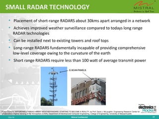
•
Scalable Array size
–
Enables same array hardware for multiple aperture configurations
•
Tile architecture
–
Reduce interconnections, simplify assembly and test processes
•
Low-peak Power
–
Allows standard surface mount packages
•
Exploit Wireless Industry Technology
–
Leverages commercial manufacturing and test processes
•
Replace existing RADARs that are used for weather and aircraft surveillance with MPAR
–
Reduced maintenance and improved availability [Higher power transmitter and mechanism for pointing the antenna]
–
Savings in uniform maintenance can be very substantial
Oct-14 Mistral Confidential 15](https://image.slidesharecdn.com/phasedarrayradar-141015042135-conversion-gate02/85/Multi-Funtion-Phased-Array-Radar-15-320.jpg)
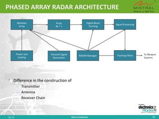


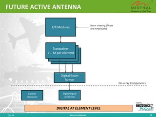
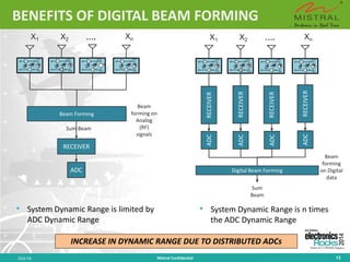
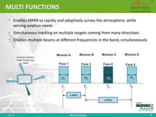
This document discusses the evolution and components of phased array radar technology. It begins by describing conventional radar systems and then introduces passive and active phased array radars, which use phase shifters and attenuators instead of mechanical movement to steer radar beams electronically. Key components of phased array radars include transmit/receive modules, digital beamforming, and GaN devices. The document outlines applications for weather surveillance and discusses multi-function phased array radars.