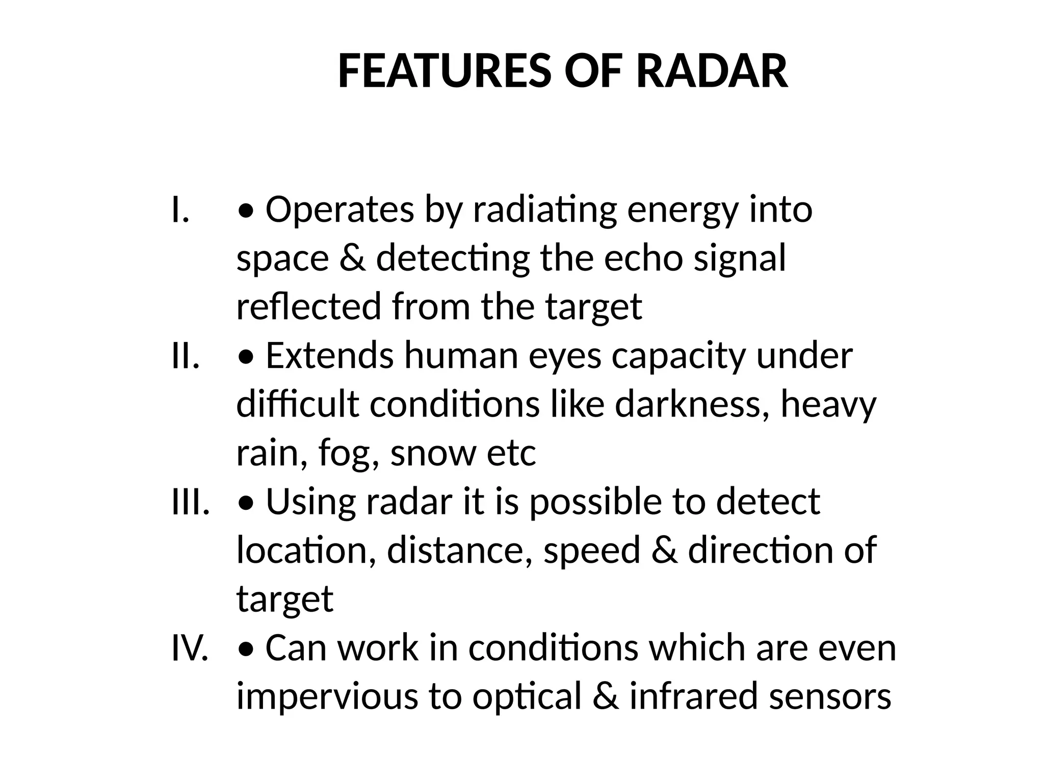
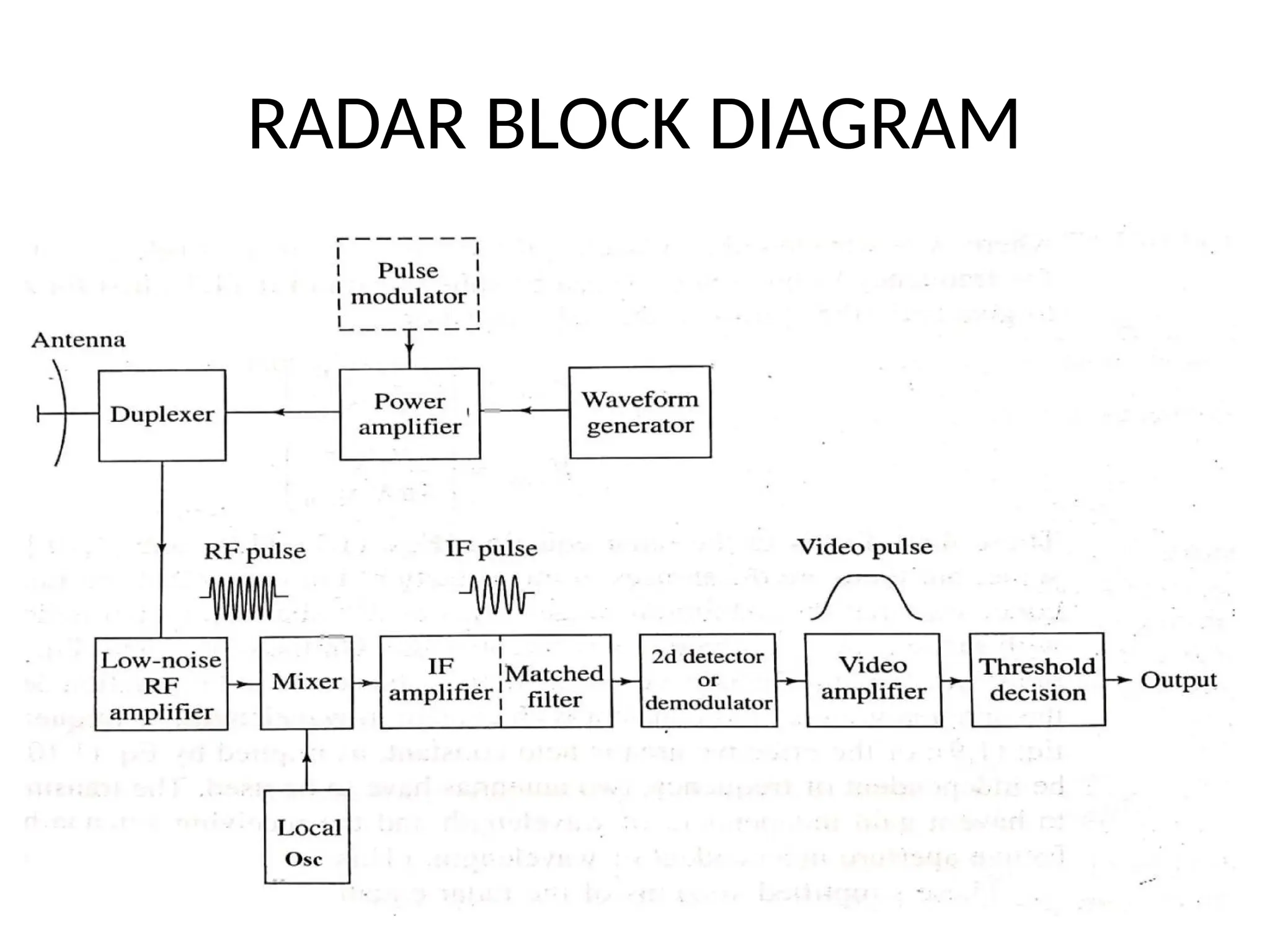
RADAR AND NAVIGATION
Module - I Introduction to Radar Radar –
concept - block diagram – operation –
frequency ranges – applications – range
equation derivation (no problems) - Radar
performance factors – minimum detectable
signal -receiver noise –Signal to Noise ratio -
Radar cross section of targets – transmitter
power – pulse repetition frequency –range
ambiguities
RADAR BASIC CONCEPTS
(Merill.l.Skolnik (1), Radiant (1.2))
• RADAR means Radio detection & ranging
• detection & location of aircraft, ships, spacecraft, vehicles
etc
• Distance is determined by measuring the time taken for
radar to travel to the target and back
• direction or angular position of target may be determined
from the direction of arrival using narrow antenna beams
• Rlative motion determined by shift in carrier frequency
FEATURES OF RADAR
I. • Operates by radiating energy into
space & detecting the echo signal
reflected from the target
II. • Extends human eyes capacity under
difficult conditions like darkness, heavy
rain, fog, snow etc
III. • Using radar it is possible to detect
location, distance, speed & direction of
target
IV. • Can work in conditions which are even
impervious to optical & infrared sensors
RADAR BLOCK DIAGRAM
Duplexer and Antenna
• Single antenna for both transmission & reception. Its
usually a gaseous device that produces a short circuit (arc
discharge) at the input to the receiver when the transmitter
is operating, so that high power flows to the antenna and not
to the receiver. On reception the duplexer directs the echo
signal to the receiver and not to the transmitter.
• Antennas can be mechanically steered parabolic reflector,
mechanically steered planar arrays, or electronically steered
phased arrays. A phased array is a collection of numerous
radiating elements whose signals combine in space to
produce a radiating plane wave.
Transmitter
Power Amplifier
• Modulator turns off /on transmitter
• Power amplifiers like klystron , travelling wave tube
, transistor amplifier or high power oscillators like
magnetron acts as transmitter.
• Output of transmitter is delivered to the antenna
by a waveguide or other forms of transmission line.
Waveform generator
• Generates radar signal at low power. This
signal acts as the input of power amplifier
Pulser Modulator
Transmitter is turned on/off by pulser with
the help of a periodic pulse

Basic Radar System Block Diagram consists of a transmitter and a receiver, each connected to a directional antenna

  • 1.
  • 2.
    Module - IIntroduction to Radar Radar – concept - block diagram – operation – frequency ranges – applications – range equation derivation (no problems) - Radar performance factors – minimum detectable signal -receiver noise –Signal to Noise ratio - Radar cross section of targets – transmitter power – pulse repetition frequency –range ambiguities
  • 3.
    RADAR BASIC CONCEPTS (Merill.l.Skolnik(1), Radiant (1.2)) • RADAR means Radio detection & ranging • detection & location of aircraft, ships, spacecraft, vehicles etc • Distance is determined by measuring the time taken for radar to travel to the target and back • direction or angular position of target may be determined from the direction of arrival using narrow antenna beams • Rlative motion determined by shift in carrier frequency
  • 4.
    FEATURES OF RADAR I.• Operates by radiating energy into space & detecting the echo signal reflected from the target II. • Extends human eyes capacity under difficult conditions like darkness, heavy rain, fog, snow etc III. • Using radar it is possible to detect location, distance, speed & direction of target IV. • Can work in conditions which are even impervious to optical & infrared sensors
  • 5.
  • 6.
    Duplexer and Antenna •Single antenna for both transmission & reception. Its usually a gaseous device that produces a short circuit (arc discharge) at the input to the receiver when the transmitter is operating, so that high power flows to the antenna and not to the receiver. On reception the duplexer directs the echo signal to the receiver and not to the transmitter. • Antennas can be mechanically steered parabolic reflector, mechanically steered planar arrays, or electronically steered phased arrays. A phased array is a collection of numerous radiating elements whose signals combine in space to produce a radiating plane wave.
  • 7.
    Transmitter Power Amplifier • Modulatorturns off /on transmitter • Power amplifiers like klystron , travelling wave tube , transistor amplifier or high power oscillators like magnetron acts as transmitter. • Output of transmitter is delivered to the antenna by a waveguide or other forms of transmission line.
  • 8.
    Waveform generator • Generatesradar signal at low power. This signal acts as the input of power amplifier Pulser Modulator Transmitter is turned on/off by pulser with the help of a periodic pulse