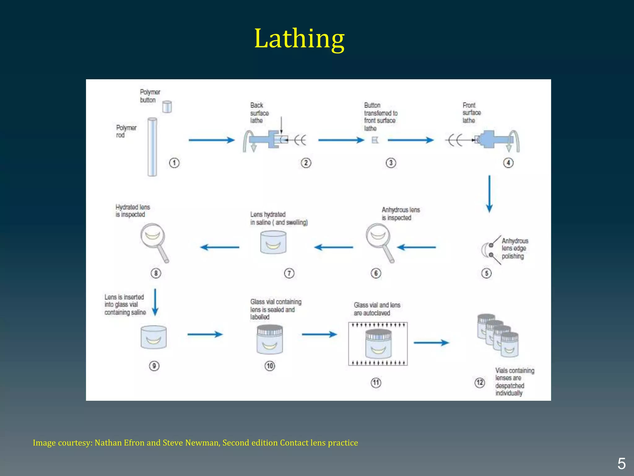
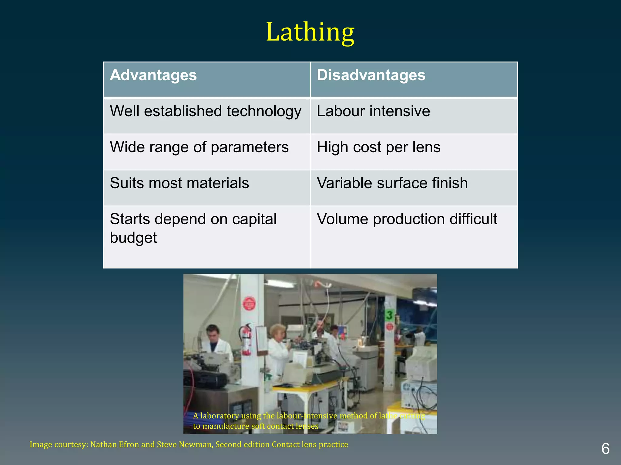
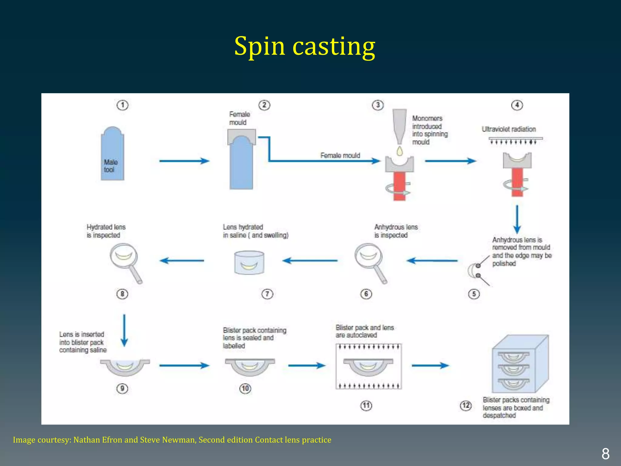
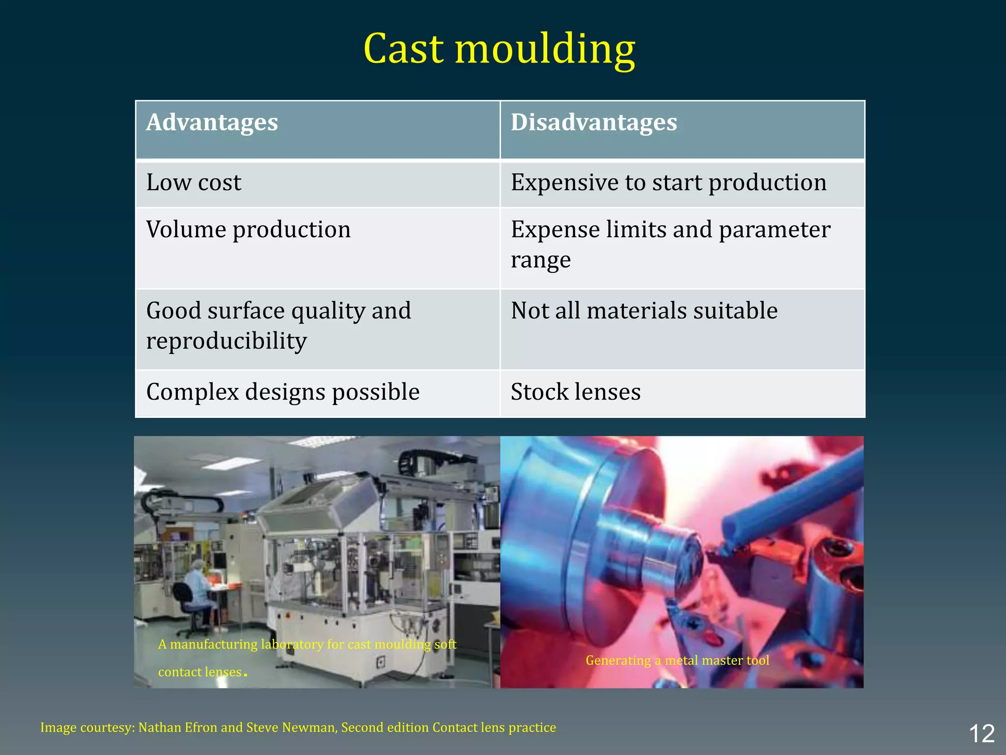
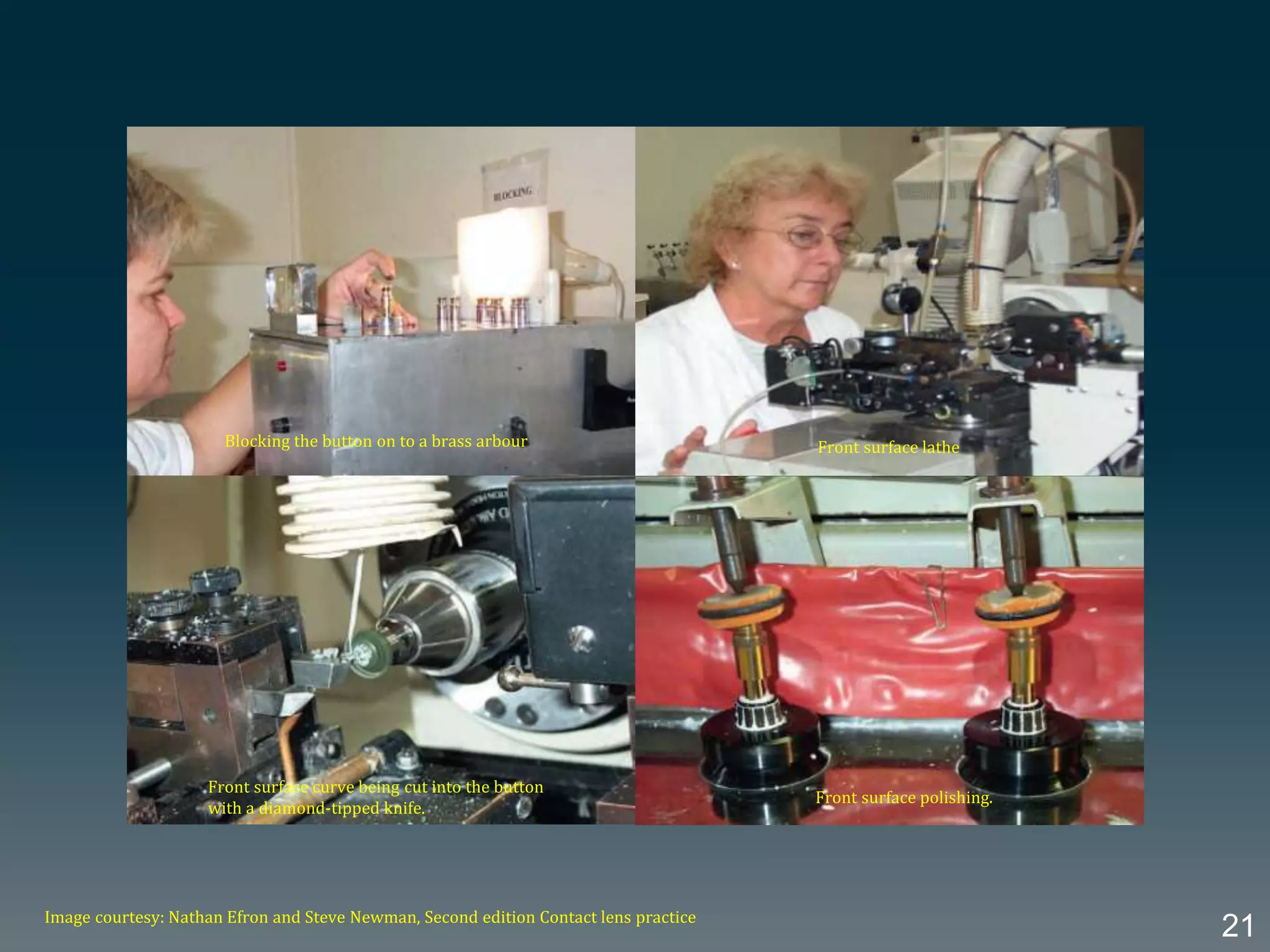
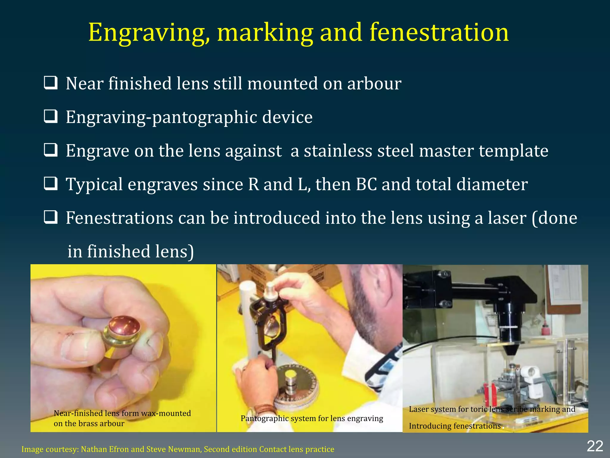
Contact lens manufacturing techniques
By,
Manoj K.M, B.Sc. Optom
Introduction
Medical devices that rests against the highly sensitive eyeball
Contact lens needs to be of the highest quality in terms of their
physical construction
Devices that correct optical defocus, the optical quality of contact
lenses must be higher
2
Soft lens manufacturing methods
 Moulding
 Spin casting
 Lathing- xerogel
 Moulding/ lathing combination
 Spin casting / lathing combination
 Moulding-stabilized soft
3
 Starts with an anhydrous button
 Strict control of environment factors especially humidity
 Numerical control increases both the complexity of the design and level
of production
 Diamond tipped tool
 Cleaning and hydration
 Sealed in normal saline
 Packed product and the autoclaved (120 degree for at least 20 minutes)
Lathing
4
Lathing
Image courtesy: Nathan Efron and Steve Newman, Second edition Contact lens practice
5
Advantages Disadvantages
Well established technology Labour intensive
Wide range of parameters High cost per lens
Suits most materials Variable surface finish
Starts depend on capital
budget
Volume production difficult
Lathing
Image courtesy: Nathan Efron and Steve Newman, Second edition Contact lens practice
6
A laboratory using the labour-intensive method of lathe cutting
to manufacture soft contact lenses
 Raw materials are liquid monomers
 Male and female mould
 Monomer’s introduced into spinning mould
 Centrifugal force and gravity defines the back surface and BOZR
 Mould defines the front surface
 Front surface finish depends on mould finish
 Back surface depends on surface tension and other properties
of the resulting polymer
Spin casting
7
Spin casting
Image courtesy: Nathan Efron and Steve Newman, Second edition Contact lens practice
8
Advantages
 Accurate reproducibility
 Precision moulds
 Controlled spin speed
 Generates free form fluid surface
 Surface and interstitial imperfections are least
Disadvantages
 Edge thickness
Image courtesy: Nathan Efron and Steve Newman, Second edition Contact lens practice
9
A manufacturing line for spin casting soft contact lenses.
 Dominant technology in high volume lens manufacture
 Matching male and female moulds
 Monomer in liquid form- introduced into a concave female
mould-front surface
 Ultraviolet transparent male mould clamped with the female
mould in controlled environment
 Polymerisation-UV light
Cast moulding
10
Cast moulding
Image courtesy: Nathan Efron and Steve Newman, Second edition Contact lens practice
11
Advantages Disadvantages
Low cost Expensive to start production
Volume production Expense limits and parameter
range
Good surface quality and
reproducibility
Not all materials suitable
Complex designs possible Stock lenses
Cast moulding
Image courtesy: Nathan Efron and Steve Newman, Second edition Contact lens practice
12
Generating a metal master tool
A manufacturing laboratory for cast moulding soft
contact lenses.
Reverse Process III
 Combinations of spin cast and lathe cut
 Spin casting the front surface and body
 Lathing the back surface to define BOZR and design
OR
 Spin casting the body and back surface
 Lathing the front surface to give BVP and design
13
Moulding/lathing combination
 Moulding the back surface and body of the lens
 Lathing the front surface
14
Stabilized soft moulding
 Inert water substitute is mixed with lens monomers before
polymerisation
 Water replaces the substitute at hydration
 Significantly less expansion on hydration
 Better optical quality and surface finish
 Quicker hydration
15
Rigid lens manufacturing
Raw materials
 Flat cylindrical buttons of 12.7 mm diameter and 4.3 mm
circumference thickness
 Supplied in various colours and the trade name imprinted
on one surface of the button
 Super gas-permeable with Dk values over 150
 Used the latest rigid gas permeable materials
Image courtesy: Nathan Efron and Steve Newman, Second edition Contact lens practice 16
Rigid lens buttons
Generating the lens back surface
 Button is first secured in a carrier or dolly
 Button clamped to a back surface lathe
 Set spinning at high rate about its central axis
 Diamond tipped tool
To obtain smooth and high quality finish
To the required size of the finished lens
 Button released from the lathe and given a brief polish
17
Image courtesy: Nathan Efron and Steve Newman, Second edition Contact lens practice
18
Back surface lathe
Button about to be mounted in dolly.
Button–dolly assembly is
collected in lathe
Image courtesy: Nathan Efron and Steve Newman, Second edition Contact lens practice
19
Back surface curve being cut into the button with a
diamond-tipped tool
Back surface polishing.
Generating the lens front surface
 The button needs to be fixed on to mount, or arbour – Blocking
 The arbour can be metal or plastic cylindrical tool,
one end dome shaped
 Heats the arbour approx. 800 C and applies low melting point wax
to dome end, or in case of plastic tool, applies UV sensitive which can
be cure to hard form
 Arbour button clamped into a front surface lathe
 Centration under magnification
 Cut is made from the edge to the centre with diamond-tipped cutter,
then with fine diamond tipped cutter
 Button is released from the lathe and mounted to polishing machine
(30 secs to 2 mins)
20
Image courtesy: Nathan Efron and Steve Newman, Second edition Contact lens practice
21
Blocking the button on to a brass arbour Front surface lathe
Front surface curve being cut into the button
with a diamond-tipped knife.
Front surface polishing.
Engraving, marking and fenestration
 Near finished lens still mounted on arbour
 Engraving-pantographic device
 Engrave on the lens against a stainless steel master template
 Typical engraves since R and L, then BC and total diameter
 Fenestrations can be introduced into the lens using a laser (done
in finished lens)
Image courtesy: Nathan Efron and Steve Newman, Second edition Contact lens practice 22
Near-finished lens form wax-mounted
on the brass arbour
Pantographic system for lens engraving
Laser system for toric lens scribe marking and
Introducing fenestrations.
Edge polishing and final inspection
 Edge polishing can be done by using a polishing machine
 The lens surface on to a concave rubber cap support
 The spindle rotates around the long axis and lowered on to a flat rotating
polishing pad and moved slowly from side to side
 After polishing, the edges are inspected using a 10X hand magnifier
 Any irregularities can be rectified manually by polishing the lens
Image courtesy: Nathan Efron and Steve Newman, Second edition Contact lens practice 23
Two lenses suction mounted to the spindles of an
edge-polishing machine, ready to be lowered on to
rotating pads.
Inspecting the lens edges using a 10× hand
magnifier Manual polishing of the lens edge.
References
 Second edition, Nathan Efron, Contact lens practice
 IACLE module 2
24
Thank you !

Contact lens manufacturing techniques

  • 1.
    Contact lens manufacturingtechniques By, Manoj K.M, B.Sc. Optom
  • 2.
    Introduction Medical devices thatrests against the highly sensitive eyeball Contact lens needs to be of the highest quality in terms of their physical construction Devices that correct optical defocus, the optical quality of contact lenses must be higher 2
  • 3.
    Soft lens manufacturingmethods  Moulding  Spin casting  Lathing- xerogel  Moulding/ lathing combination  Spin casting / lathing combination  Moulding-stabilized soft 3
  • 4.
     Starts withan anhydrous button  Strict control of environment factors especially humidity  Numerical control increases both the complexity of the design and level of production  Diamond tipped tool  Cleaning and hydration  Sealed in normal saline  Packed product and the autoclaved (120 degree for at least 20 minutes) Lathing 4
  • 5.
    Lathing Image courtesy: NathanEfron and Steve Newman, Second edition Contact lens practice 5
  • 6.
    Advantages Disadvantages Well establishedtechnology Labour intensive Wide range of parameters High cost per lens Suits most materials Variable surface finish Starts depend on capital budget Volume production difficult Lathing Image courtesy: Nathan Efron and Steve Newman, Second edition Contact lens practice 6 A laboratory using the labour-intensive method of lathe cutting to manufacture soft contact lenses
  • 7.
     Raw materialsare liquid monomers  Male and female mould  Monomer’s introduced into spinning mould  Centrifugal force and gravity defines the back surface and BOZR  Mould defines the front surface  Front surface finish depends on mould finish  Back surface depends on surface tension and other properties of the resulting polymer Spin casting 7
  • 8.
    Spin casting Image courtesy:Nathan Efron and Steve Newman, Second edition Contact lens practice 8
  • 9.
    Advantages  Accurate reproducibility Precision moulds  Controlled spin speed  Generates free form fluid surface  Surface and interstitial imperfections are least Disadvantages  Edge thickness Image courtesy: Nathan Efron and Steve Newman, Second edition Contact lens practice 9 A manufacturing line for spin casting soft contact lenses.
  • 10.
     Dominant technologyin high volume lens manufacture  Matching male and female moulds  Monomer in liquid form- introduced into a concave female mould-front surface  Ultraviolet transparent male mould clamped with the female mould in controlled environment  Polymerisation-UV light Cast moulding 10
  • 11.
    Cast moulding Image courtesy:Nathan Efron and Steve Newman, Second edition Contact lens practice 11
  • 12.
    Advantages Disadvantages Low costExpensive to start production Volume production Expense limits and parameter range Good surface quality and reproducibility Not all materials suitable Complex designs possible Stock lenses Cast moulding Image courtesy: Nathan Efron and Steve Newman, Second edition Contact lens practice 12 Generating a metal master tool A manufacturing laboratory for cast moulding soft contact lenses.
  • 13.
    Reverse Process III Combinations of spin cast and lathe cut  Spin casting the front surface and body  Lathing the back surface to define BOZR and design OR  Spin casting the body and back surface  Lathing the front surface to give BVP and design 13
  • 14.
    Moulding/lathing combination  Mouldingthe back surface and body of the lens  Lathing the front surface 14
  • 15.
    Stabilized soft moulding Inert water substitute is mixed with lens monomers before polymerisation  Water replaces the substitute at hydration  Significantly less expansion on hydration  Better optical quality and surface finish  Quicker hydration 15
  • 16.
    Rigid lens manufacturing Rawmaterials  Flat cylindrical buttons of 12.7 mm diameter and 4.3 mm circumference thickness  Supplied in various colours and the trade name imprinted on one surface of the button  Super gas-permeable with Dk values over 150  Used the latest rigid gas permeable materials Image courtesy: Nathan Efron and Steve Newman, Second edition Contact lens practice 16 Rigid lens buttons
  • 17.
    Generating the lensback surface  Button is first secured in a carrier or dolly  Button clamped to a back surface lathe  Set spinning at high rate about its central axis  Diamond tipped tool To obtain smooth and high quality finish To the required size of the finished lens  Button released from the lathe and given a brief polish 17
  • 18.
    Image courtesy: NathanEfron and Steve Newman, Second edition Contact lens practice 18 Back surface lathe Button about to be mounted in dolly. Button–dolly assembly is collected in lathe
  • 19.
    Image courtesy: NathanEfron and Steve Newman, Second edition Contact lens practice 19 Back surface curve being cut into the button with a diamond-tipped tool Back surface polishing.
  • 20.
    Generating the lensfront surface  The button needs to be fixed on to mount, or arbour – Blocking  The arbour can be metal or plastic cylindrical tool, one end dome shaped  Heats the arbour approx. 800 C and applies low melting point wax to dome end, or in case of plastic tool, applies UV sensitive which can be cure to hard form  Arbour button clamped into a front surface lathe  Centration under magnification  Cut is made from the edge to the centre with diamond-tipped cutter, then with fine diamond tipped cutter  Button is released from the lathe and mounted to polishing machine (30 secs to 2 mins) 20
  • 21.
    Image courtesy: NathanEfron and Steve Newman, Second edition Contact lens practice 21 Blocking the button on to a brass arbour Front surface lathe Front surface curve being cut into the button with a diamond-tipped knife. Front surface polishing.
  • 22.
    Engraving, marking andfenestration  Near finished lens still mounted on arbour  Engraving-pantographic device  Engrave on the lens against a stainless steel master template  Typical engraves since R and L, then BC and total diameter  Fenestrations can be introduced into the lens using a laser (done in finished lens) Image courtesy: Nathan Efron and Steve Newman, Second edition Contact lens practice 22 Near-finished lens form wax-mounted on the brass arbour Pantographic system for lens engraving Laser system for toric lens scribe marking and Introducing fenestrations.
  • 23.
    Edge polishing andfinal inspection  Edge polishing can be done by using a polishing machine  The lens surface on to a concave rubber cap support  The spindle rotates around the long axis and lowered on to a flat rotating polishing pad and moved slowly from side to side  After polishing, the edges are inspected using a 10X hand magnifier  Any irregularities can be rectified manually by polishing the lens Image courtesy: Nathan Efron and Steve Newman, Second edition Contact lens practice 23 Two lenses suction mounted to the spindles of an edge-polishing machine, ready to be lowered on to rotating pads. Inspecting the lens edges using a 10× hand magnifier Manual polishing of the lens edge.
  • 24.
    References  Second edition,Nathan Efron, Contact lens practice  IACLE module 2 24
  • 25.

Editor's Notes

  • #4 Molding - xerogel. Monomers are mixed and then poured into a mold (single or double sided) in the absence of water/water vapour (and usually air/oxygen as well) at tightly controlled temperatures. • Spin-casting. An open-backed mold is spun as a small centrifuge. The mold defines the front surface of the lens. Rotational velocity, surface tension and gravity combine to define the back surface. • Lathing - xerogel. An anhydrous button of lens material is lathed conventionally in a controlled atmosphere. Manufacturers are researching methods of eliminating the need for surface polishing by the application of high-precision engineering principles and other advances such as air bearings and anti-vibration mounts. • Molding/Lathing combination. Usually a combination of molding the back surface and body of the lens and lathing the front surface. • Spin-casting/Lathing combination. Usually spin-casting the front surface and body of the lens and lathing the back surface. • Molding - Stabilized Soft. In this recent innovation, a space-taking inert diluent is included in the mix of monomers during molding/polymerization. The diluent is replaced by water at a later stage. The final product is quick to hydrate fully, undergoes minimal expansion on final hydration and provides high quality optics and surface finish.
  • #6 The process of manufacturing a soft contact lens by lathe cutting. (1) The dry polymer is supplied as a rod or button. (2) A polymer button is placed on a lathe; the button spins and a diamond tool is advanced towards the button to generate the lens back surface. (3) The button is released from the back surface lathe. (4) The button is mounted on a front surface lathe with adhesive wax; the button spins and a diamond tool is advanced towards the button to generate the lens front surface. (5) The dry lens is removed from the lathe and the edges are polished. (6) The lens is inspected at 17× magnification. (7) The dry lens is placed in saline to hydrate the lens, which swells to its final soft lens form. (8) The hydrated soft lens is inspected at 10× magnification. (9) The soft lens is inserted into a glass vial containing saline. (10) The glass vial is sealed and labelled. (11) The sealed glass vial containing the lens is sterilized in an autoclave. (12) The individual glass vials are despatched.
  • #8 Change to 7 the slide
  • #9 Auto calve 120 0 C for 15 to 20 minutes Once the blister pack is opened, what will happened to the content in blister solution? What will be the base curve value for selecting the mould based on the power? The process of manufacturing a soft contact lens by spin casting. (1) A male tool is machined from stainless steel; the contour of the tool head will define the shape of the anterior lens surface. The same tool is used to make hundreds of thousands of moulds. (2) A female mould is made by pressing the male tool into molten polypropylene, which cools and sets. (3) The female mould is mounted, with the concavity facing upwards, in a spindle that spins about the lens axis, and liquid monomers are introduced into the spinning mould. (4) The monomers in the spinning mould are irradiated with ultraviolet light to initiate lens polymerization. (5) The dry lens is removed from the mould, the lens edge may be polished and the mould is discarded. (6) The edge of the dry lens is inspected at 10× magnification. (7) The dry lens is placed in saline, which hydrates the lens, causing it to swell to its final soft lens form. (8) The hydrated soft lens is inspected at 10× magnification. (9) The soft lens is inserted into a blister pack containing saline. (10) The blister pack is sealed with a special foil, and a label is stuck on to this. (11) The sealed blister pack containing the lens is sterilized in an autoclave. (12) The individual blister packs are inserted into packages, typically in multiples of either three or six lenses.
  • #10 Is the minus lens is a disadvantage for edge thickness in spin casting ??
  • #12 The process of manufacturing a soft contact lens by cast moulding. (1) Male and female tools are machined from stainless steel; the contour of the male tool head will define the shape of the anterior lens surface, and the contour of the female tool head will define the shape of the posterior lens surface. The same tools are used to make hundreds of thousands of moulds. (2) Male and female moulds are made by pressing the tools into molten polypropylene, which cools and sets. (3) The female mould is mounted in an accurate aligning fixture, with the concavity facing upwards, and liquid monomers are introduced into the concavity. (4) The male mould is registered over the female mould and the two moulds are clipped together. (5) Excess polymer is squeezed out from the sides of the mould. (6) The monomers inside the mould assembly are irradiated with ultraviolet light or thermal energy to initiate lens polymerization. (7) The dry lens is removed from the mould and the moulds are discarded. The final stages of lens production are essentially the same as for spin casting, which is illustrated in steps 6–12
  • #13 The master tools are used to make hundreds of thousands of male and female moulds.
  • #14 Picture for REVERSE III process
  • #18 Change the diamond cutter