1. EDC-UNITV Question&answer
GRIET-ECE G.Surekha Page 1
UNIT-V SMALL SIGNAL LOW FREQUENCY BJT MODEL
1. List out the advantages of h-parameters.
1. h-parameters are real numbers at audio frequencies.
2. These are easy to measure.
3. h-parameter can also be obtained from the transistor static characteristic
curves.
4. h-parameters are convenient to use in circuit analysis and design.
5. A set of h-parameters is specified for many transistors by the manufacturers
2. Draw the h-parameter circuit and its equivalent circuit in CE
configuration.
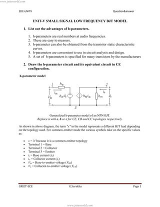
h-parameter model
Generalized h-parameter model of an NPN BJT.
Replace x with e, b or c for CE, CB and CC topologies respectively.
As shown in above diagram, the term "x" in the model represents a different BJT lead depending
on the topology used. For common-emitter mode the various symbols take on the specific values
as:
x = 'e' because it is a common-emitter topology
Terminal 1 = Base
Terminal 2 = Collector
Terminal 3 = Emitter
ii = Base current (ib)
io = Collector current (ic)
Vin = Base-to-emitter voltage (VBE)
Vo = Collector-to-emitter voltage (VCE)
www.jntuworld.com
www.jntuworld.com
2. EDC-UNITV Question&answer
GRIET-ECE G.Surekha Page 2
and the h-parameters are given by:
hie – The input impedance of the transistor (corresponding to the emitter resistance re).
hre – Represents the dependence of the transistor's IB–VBE curve on the value of VCE. It is
usually very small and is often neglected (assumed to be zero).
hfe – The current-gain of the transistor. This parameter is often specified as hFE or the DC
current-gain (βDC) in datasheets.
hoe – The output impedance of transistor. This term is usually specified as an admittance
and has to be inverted to convert it to an impedance.
For the CE topology, an approximate h-parameter model is commonly used which further
simplifies the circuit analysis. For this the hoe and hre parameters are neglected (that is, they are
set to infinity and zero, respectively). It should also be noted that the h-parameter model as
shown is suited to low-frequency, small-signal analysis. For high-frequency analysis the inter-
electrode capacitances that are important at high frequencies must be added.
3. Summarize salient features of characteristics of BJT operating in CE, CB, CC configurations.
COMPARISON OF CB, CE, CC CONFIGURATIONS:
www.jntuworld.com
www.jntuworld.com
3. EDC-UNITV Question&answer
GRIET-ECE G.Surekha Page 3
S. No. Property CB CE CC
1 Input Resistance Low ( 100 ) Moderate( 750 ) High ( 750k )
2 Output resistance High ( 450k) Moderate ( 45k) Low ( 75 )
3 Current gain 1 High High
4 Voltage gain 150 500 < 1
5 Phase shift between
input and output
voltages
0 or 360 180 0 or 360
6 Applications High frequency
circuits
AF circuits Impedance
matching.
www.jntuworld.com
www.jntuworld.com