SlideShare a Scribd company logo
1 of 15
M.KARTHIKEYAN
ASSISTANT PROFESSOR
DEPARTMENT OF MECHANICAL ENGINEERING
AAA COLLEGE OF ENGINEERING & TECHNOLOGY, SIVAKASI
karthikeyan@aaacet.ac.in
ME8097 NON DESTRUCTIVE
TESTING AND EVALUATION
UNIT IV ULTRASONIC TESTING (UT) AND ACOUSTIC
EMISSION (AE)
1. Ultrasonic Testing-Principle,
2. Transducers,
3. Transmission and pulse-echo method,
4. Straight beam and angle beam,
5. Instrumentation,
6. Data representation, A/Scan, B-scan, C-scan.
7. Phased Array Ultrasound, Time of Flight Diffraction.
8. Acoustic Emission Technique – Principle,
9. AE parameters, Applications
INSPECTION METHODS
1. PULSE ECHO METHOD
2. THROUGH TRANSMISSION METHOD
3. ANGLE BEAM ULTRASONIC TESTING
4. IMMERSION ULTRASONIC TESTING
PULSE ECHO METHOD
 A typical UT inspection system consists of several functional
units, such as the pulser/receiver, transducer, and display
devices.
 A pulser/receiver is an electronic device that can produce high
voltage electrical pulses.
 Driven by the pulser, the transducer generates high frequency
ultrasonic energy.
 The sound energy is introduced and propagates through the
materials in the form of waves.
 When there is a discontinuity (such as a crack) in the wave path,
part of the energy will be reflected back from the flaw surface.
 The reflected wave signal is transformed into an electrical signal
by the transducer and is displayed on a screen.
 In the applet below, the reflected signal strength is displayed
versus the time from signal generation to when a echo was
received.
 Signal travel time can be directly related to the distance that
the signal traveled.
 From the signal, information about the reflector location, size,
orientation and other features can sometimes be gained.
2. THROUGH TRANSMISSION METHOD
 Through-transmission ultrasonic testing (UT) is used for
detection, verification, sizing, and growth rate monitoring of
cracks in piping, vessels, cylindrical shapes, and sometimes
noncylindrical shapes.
 Through-transmission UT is most widely known as a method of
inspection in automated immersion testing for detection of
laminars in steel or disbonding in composite materials where
two opposite and parallel surfaces can be used for scanning
 Through-transmission UT is a two transducer technique in a
pitch-catch arrangement.
 While there are many types of UT techniques, because of the
wide variety of component shapes, sizes, and orientations it is
sometimes valuable to have an alternative technique for
verification, such as through-transmission
The advantages of through transmission are:
 Less attenuation of sound energy
 No probe ringing
 No dead zone on the screen
 The orientation of a defect does not matter in the way that it
does on the pulse echo display.
The disadvantages are:
 The defect cannot be located
 The defect cannot be identified
 The component surfaces must be parallel
 Vertical defects do not show
 The process must be automated
 There must be access to both sides of the component.
In an A scan presentation, the amplitude of vertical
indications on the screen represents the:
(a) Amount of ultrasonic sound energy returning to the
search unit
(b) Distance travelled by the search unit
(c) Thickness of material being tested
(d) Elapsed time since the ultrasonic pulse was generated
MCQ - 1
An instrument display in which the horizontal base line
represents elapsed time and the vertical deflection
represents signal amplitudes is called:
(a) A scan
(b) B scan
(c) C scan
(d) A time line display
MCQ - 2
A cross section view of a test piece is produced by which of
the following?
(a) A scan
(b) B scan
(c) C scan
(d) A time line display
MCQ - 3
The process of comparing an instrument or device with a
standard is called:
(a) Angulation
(b) Calibration
(c) Attenuation
(d) Correlation
MCQ - 4
Which technique would most likely be used to examine a
weld, with the weld cap still in place?
(a) Through transmission testing
(b) Angle beam testing
(c) Straight beam testing
(d) None of the above
MCQ - 5

More Related Content

What's hot

L32 straight beam and angle beam
L32 straight beam and angle beamL32 straight beam and angle beam
L32 straight beam and angle beamkarthi keyan
 
ULTRASONIC TESTING (UT) & ACOUSTIC EMISSION (AE)
ULTRASONIC TESTING (UT)  &  ACOUSTIC EMISSION (AE)ULTRASONIC TESTING (UT)  &  ACOUSTIC EMISSION (AE)
ULTRASONIC TESTING (UT) & ACOUSTIC EMISSION (AE)laxtwinsme
 
Introduction to NDT and Visual Inspection
Introduction to NDT and Visual Inspection Introduction to NDT and Visual Inspection
Introduction to NDT and Visual Inspection Hareesh K
 
L35 phased array ultrasound & time of flight diffraction
L35 phased array ultrasound & time of flight diffractionL35 phased array ultrasound & time of flight diffraction
L35 phased array ultrasound & time of flight diffractionkarthi keyan
 
acoustic emission
 acoustic emission acoustic emission
acoustic emissionkarthi keyan
 
Acoustic emission sensors, equipment
Acoustic emission sensors, equipment Acoustic emission sensors, equipment
Acoustic emission sensors, equipment mboria
 
Radiographic Testing (RT)- NDT
Radiographic Testing (RT)- NDTRadiographic Testing (RT)- NDT
Radiographic Testing (RT)- NDTSukesh O P
 
Ultrasonic testing
Ultrasonic testingUltrasonic testing
Ultrasonic testingzoha nasir
 
Liquid penetrant testing
Liquid penetrant testingLiquid penetrant testing
Liquid penetrant testingyash patel
 
L34 data representation, ascan, b scan, c-scan.
L34 data representation, ascan, b scan, c-scan.L34 data representation, ascan, b scan, c-scan.
L34 data representation, ascan, b scan, c-scan.karthi keyan
 
Eddy current testing
Eddy current testingEddy current testing
Eddy current testingzoha nasir
 
Magnetic Particle Inspection (MPI)- NDT
Magnetic Particle Inspection (MPI)- NDTMagnetic Particle Inspection (MPI)- NDT
Magnetic Particle Inspection (MPI)- NDTSukesh O P
 
Radiography techniques
Radiography techniquesRadiography techniques
Radiography techniquesVertika Nigam
 

What's hot (20)

5.ULTRASONIC TESTING
5.ULTRASONIC TESTING5.ULTRASONIC TESTING
5.ULTRASONIC TESTING
 
Eddy current testing
Eddy current testingEddy current testing
Eddy current testing
 
L32 straight beam and angle beam
L32 straight beam and angle beamL32 straight beam and angle beam
L32 straight beam and angle beam
 
ULTRASONIC TESTING (UT) & ACOUSTIC EMISSION (AE)
ULTRASONIC TESTING (UT)  &  ACOUSTIC EMISSION (AE)ULTRASONIC TESTING (UT)  &  ACOUSTIC EMISSION (AE)
ULTRASONIC TESTING (UT) & ACOUSTIC EMISSION (AE)
 
Introduction to NDT and Visual Inspection
Introduction to NDT and Visual Inspection Introduction to NDT and Visual Inspection
Introduction to NDT and Visual Inspection
 
L35 phased array ultrasound & time of flight diffraction
L35 phased array ultrasound & time of flight diffractionL35 phased array ultrasound & time of flight diffraction
L35 phased array ultrasound & time of flight diffraction
 
acoustic emission
 acoustic emission acoustic emission
acoustic emission
 
Acoustic emission sensors, equipment
Acoustic emission sensors, equipment Acoustic emission sensors, equipment
Acoustic emission sensors, equipment
 
Radiographic Testing (RT)- NDT
Radiographic Testing (RT)- NDTRadiographic Testing (RT)- NDT
Radiographic Testing (RT)- NDT
 
Ultrasonic testing
Ultrasonic testingUltrasonic testing
Ultrasonic testing
 
Eddy current inspection
Eddy current inspection Eddy current inspection
Eddy current inspection
 
Liquid penetrant testing
Liquid penetrant testingLiquid penetrant testing
Liquid penetrant testing
 
Introduction to Ultrasonic Testing
Introduction to Ultrasonic TestingIntroduction to Ultrasonic Testing
Introduction to Ultrasonic Testing
 
L34 data representation, ascan, b scan, c-scan.
L34 data representation, ascan, b scan, c-scan.L34 data representation, ascan, b scan, c-scan.
L34 data representation, ascan, b scan, c-scan.
 
Eddy current testing
Eddy current testingEddy current testing
Eddy current testing
 
EDDY CURRENT TESTING
EDDY CURRENT TESTINGEDDY CURRENT TESTING
EDDY CURRENT TESTING
 
L30 transducers
L30 transducersL30 transducers
L30 transducers
 
Magnetic Particle Inspection (MPI)- NDT
Magnetic Particle Inspection (MPI)- NDTMagnetic Particle Inspection (MPI)- NDT
Magnetic Particle Inspection (MPI)- NDT
 
Radiography techniques
Radiography techniquesRadiography techniques
Radiography techniques
 
Six ndt methods
Six ndt methodsSix ndt methods
Six ndt methods
 

Similar to L31 transmission and pulse echo method

UT: A Review Of New Techniques
UT: A Review Of New TechniquesUT: A Review Of New Techniques
UT: A Review Of New TechniquesOlympus IMS
 
L29 ultrasonic testing principle
L29 ultrasonic testing principleL29 ultrasonic testing principle
L29 ultrasonic testing principlekarthi keyan
 
PRESENTATION ESA.pptx
PRESENTATION ESA.pptxPRESENTATION ESA.pptx
PRESENTATION ESA.pptxChandu794921
 
Ultrasonic testing
Ultrasonic testingUltrasonic testing
Ultrasonic testingShahzad Baig
 
Advance NDT Methods
Advance NDT MethodsAdvance NDT Methods
Advance NDT Methodsaman1312
 
International Journal of Engineering Research and Development (IJERD)
International Journal of Engineering Research and Development (IJERD)International Journal of Engineering Research and Development (IJERD)
International Journal of Engineering Research and Development (IJERD)IJERD Editor
 
An investigation into non destructive testing techniques a specific case s...
An investigation into non destructive testing techniques    a specific case s...An investigation into non destructive testing techniques    a specific case s...
An investigation into non destructive testing techniques a specific case s...eSAT Journals
 
Ultrasonic Testing Equipments: A Complete Guide
Ultrasonic Testing Equipments:  A Complete GuideUltrasonic Testing Equipments:  A Complete Guide
Ultrasonic Testing Equipments: A Complete GuideManaswiMumbarkar
 
New microsoft power point presentation
New microsoft power point presentationNew microsoft power point presentation
New microsoft power point presentationAnkur singh
 
Intro to ultrasonics
Intro to ultrasonicsIntro to ultrasonics
Intro to ultrasonicsJoy Bhowmik
 
Ultrasonic testing report-JUNE 2018
Ultrasonic testing report-JUNE 2018Ultrasonic testing report-JUNE 2018
Ultrasonic testing report-JUNE 2018musadoto
 
L37 ae parameters, applications
L37 ae parameters, applicationsL37 ae parameters, applications
L37 ae parameters, applicationskarthi keyan
 
Ultrasonic ILI Removes Crack Depth-Sizing Limits
Ultrasonic ILI Removes Crack Depth-Sizing LimitsUltrasonic ILI Removes Crack Depth-Sizing Limits
Ultrasonic ILI Removes Crack Depth-Sizing LimitsNDT Global
 

Similar to L31 transmission and pulse echo method (20)

UT: A Review Of New Techniques
UT: A Review Of New TechniquesUT: A Review Of New Techniques
UT: A Review Of New Techniques
 
NDT Techniques.pptx
NDT Techniques.pptxNDT Techniques.pptx
NDT Techniques.pptx
 
L29 ultrasonic testing principle
L29 ultrasonic testing principleL29 ultrasonic testing principle
L29 ultrasonic testing principle
 
UNIT 4.ppt
UNIT 4.pptUNIT 4.ppt
UNIT 4.ppt
 
PRESENTATION ESA.pptx
PRESENTATION ESA.pptxPRESENTATION ESA.pptx
PRESENTATION ESA.pptx
 
ultrasonic test
 ultrasonic test ultrasonic test
ultrasonic test
 
Ultrasonic testing
Ultrasonic testingUltrasonic testing
Ultrasonic testing
 
1-5
1-51-5
1-5
 
Advance NDT Methods
Advance NDT MethodsAdvance NDT Methods
Advance NDT Methods
 
International Journal of Engineering Research and Development (IJERD)
International Journal of Engineering Research and Development (IJERD)International Journal of Engineering Research and Development (IJERD)
International Journal of Engineering Research and Development (IJERD)
 
An investigation into non destructive testing techniques a specific case s...
An investigation into non destructive testing techniques    a specific case s...An investigation into non destructive testing techniques    a specific case s...
An investigation into non destructive testing techniques a specific case s...
 
Ultrasonic Testing Equipments: A Complete Guide
Ultrasonic Testing Equipments:  A Complete GuideUltrasonic Testing Equipments:  A Complete Guide
Ultrasonic Testing Equipments: A Complete Guide
 
Intro to ultrasonics
Intro to ultrasonicsIntro to ultrasonics
Intro to ultrasonics
 
Acoustic Emission testing
Acoustic Emission testingAcoustic Emission testing
Acoustic Emission testing
 
Paut full notes
Paut  full notesPaut  full notes
Paut full notes
 
New microsoft power point presentation
New microsoft power point presentationNew microsoft power point presentation
New microsoft power point presentation
 
Intro to ultrasonics
Intro to ultrasonicsIntro to ultrasonics
Intro to ultrasonics
 
Ultrasonic testing report-JUNE 2018
Ultrasonic testing report-JUNE 2018Ultrasonic testing report-JUNE 2018
Ultrasonic testing report-JUNE 2018
 
L37 ae parameters, applications
L37 ae parameters, applicationsL37 ae parameters, applications
L37 ae parameters, applications
 
Ultrasonic ILI Removes Crack Depth-Sizing Limits
Ultrasonic ILI Removes Crack Depth-Sizing LimitsUltrasonic ILI Removes Crack Depth-Sizing Limits
Ultrasonic ILI Removes Crack Depth-Sizing Limits
 

More from karthi keyan

ORO551 RENEWABLE ENERGY SOURCES - FULL NOTES
ORO551 RENEWABLE ENERGY SOURCES - FULL NOTESORO551 RENEWABLE ENERGY SOURCES - FULL NOTES
ORO551 RENEWABLE ENERGY SOURCES - FULL NOTESkarthi keyan
 
CME 397 - SURFACE ENGINEERING - UNIT 1 FULL NOTES
CME 397 - SURFACE ENGINEERING - UNIT 1 FULL NOTESCME 397 - SURFACE ENGINEERING - UNIT 1 FULL NOTES
CME 397 - SURFACE ENGINEERING - UNIT 1 FULL NOTESkarthi keyan
 
cme397 surface engineering unit 5 part A questions and answers
cme397 surface engineering unit 5 part A questions and answerscme397 surface engineering unit 5 part A questions and answers
cme397 surface engineering unit 5 part A questions and answerskarthi keyan
 
types (classification) of cutting tool materials.docx
types (classification) of cutting tool materials.docxtypes (classification) of cutting tool materials.docx
types (classification) of cutting tool materials.docxkarthi keyan
 
difference between orthogonal vs oblique cutting.docx
difference between orthogonal vs oblique cutting.docxdifference between orthogonal vs oblique cutting.docx
difference between orthogonal vs oblique cutting.docxkarthi keyan
 
me3493 manufacturing technology unit 1 Part A
me3493 manufacturing technology unit 1 Part Ame3493 manufacturing technology unit 1 Part A
me3493 manufacturing technology unit 1 Part Akarthi keyan
 
types of cutting Tool wear mechanisms.docx
types of cutting Tool wear mechanisms.docxtypes of cutting Tool wear mechanisms.docx
types of cutting Tool wear mechanisms.docxkarthi keyan
 
laser surface alloying (LSA) - Surface treatments
laser surface alloying (LSA) - Surface treatmentslaser surface alloying (LSA) - Surface treatments
laser surface alloying (LSA) - Surface treatmentskarthi keyan
 
CME397 THERMAL SPRAYING process (CME397)
CME397 THERMAL SPRAYING process (CME397)CME397 THERMAL SPRAYING process (CME397)
CME397 THERMAL SPRAYING process (CME397)karthi keyan
 
Chemical vapour deposition (CVD) process
Chemical vapour deposition (CVD) processChemical vapour deposition (CVD) process
Chemical vapour deposition (CVD) processkarthi keyan
 
Computed Radiography and Computed Tomography
Computed Radiography and Computed TomographyComputed Radiography and Computed Tomography
Computed Radiography and Computed Tomographykarthi keyan
 
characteristics of films - graininess, density, speed, contrast
characteristics of films - graininess, density, speed, contrastcharacteristics of films - graininess, density, speed, contrast
characteristics of films - graininess, density, speed, contrastkarthi keyan
 
characteristic curves & Penetrameters,
 characteristic curves & Penetrameters, characteristic curves & Penetrameters,
characteristic curves & Penetrameters,karthi keyan
 
geometric Factors
 geometric Factors geometric Factors
geometric Factorskarthi keyan
 
use of filters and screens
 use of filters and screens use of filters and screens
use of filters and screenskarthi keyan
 
L40 film and film less techniques
L40 film and film less techniquesL40 film and film less techniques
L40 film and film less techniqueskarthi keyan
 
interaction of x ray with matter
interaction of x ray with matterinteraction of x ray with matter
interaction of x ray with matterkarthi keyan
 
electron microscopy tem
electron microscopy   temelectron microscopy   tem
electron microscopy temkarthi keyan
 

More from karthi keyan (20)

ORO551 RENEWABLE ENERGY SOURCES - FULL NOTES
ORO551 RENEWABLE ENERGY SOURCES - FULL NOTESORO551 RENEWABLE ENERGY SOURCES - FULL NOTES
ORO551 RENEWABLE ENERGY SOURCES - FULL NOTES
 
CME 397 - SURFACE ENGINEERING - UNIT 1 FULL NOTES
CME 397 - SURFACE ENGINEERING - UNIT 1 FULL NOTESCME 397 - SURFACE ENGINEERING - UNIT 1 FULL NOTES
CME 397 - SURFACE ENGINEERING - UNIT 1 FULL NOTES
 
cme397 surface engineering unit 5 part A questions and answers
cme397 surface engineering unit 5 part A questions and answerscme397 surface engineering unit 5 part A questions and answers
cme397 surface engineering unit 5 part A questions and answers
 
types (classification) of cutting tool materials.docx
types (classification) of cutting tool materials.docxtypes (classification) of cutting tool materials.docx
types (classification) of cutting tool materials.docx
 
difference between orthogonal vs oblique cutting.docx
difference between orthogonal vs oblique cutting.docxdifference between orthogonal vs oblique cutting.docx
difference between orthogonal vs oblique cutting.docx
 
me3493 manufacturing technology unit 1 Part A
me3493 manufacturing technology unit 1 Part Ame3493 manufacturing technology unit 1 Part A
me3493 manufacturing technology unit 1 Part A
 
types of cutting Tool wear mechanisms.docx
types of cutting Tool wear mechanisms.docxtypes of cutting Tool wear mechanisms.docx
types of cutting Tool wear mechanisms.docx
 
laser surface alloying (LSA) - Surface treatments
laser surface alloying (LSA) - Surface treatmentslaser surface alloying (LSA) - Surface treatments
laser surface alloying (LSA) - Surface treatments
 
CME397 THERMAL SPRAYING process (CME397)
CME397 THERMAL SPRAYING process (CME397)CME397 THERMAL SPRAYING process (CME397)
CME397 THERMAL SPRAYING process (CME397)
 
Chemical vapour deposition (CVD) process
Chemical vapour deposition (CVD) processChemical vapour deposition (CVD) process
Chemical vapour deposition (CVD) process
 
Computed Radiography and Computed Tomography
Computed Radiography and Computed TomographyComputed Radiography and Computed Tomography
Computed Radiography and Computed Tomography
 
exposure charts
 exposure charts exposure charts
exposure charts
 
characteristics of films - graininess, density, speed, contrast
characteristics of films - graininess, density, speed, contrastcharacteristics of films - graininess, density, speed, contrast
characteristics of films - graininess, density, speed, contrast
 
characteristic curves & Penetrameters,
 characteristic curves & Penetrameters, characteristic curves & Penetrameters,
characteristic curves & Penetrameters,
 
geometric Factors
 geometric Factors geometric Factors
geometric Factors
 
use of filters and screens
 use of filters and screens use of filters and screens
use of filters and screens
 
L40 film and film less techniques
L40 film and film less techniquesL40 film and film less techniques
L40 film and film less techniques
 
interaction of x ray with matter
interaction of x ray with matterinteraction of x ray with matter
interaction of x ray with matter
 
eddy current test
eddy current testeddy current test
eddy current test
 
electron microscopy tem
electron microscopy   temelectron microscopy   tem
electron microscopy tem
 

Recently uploaded

Computer Graphics Introduction To Curves
Computer Graphics Introduction To CurvesComputer Graphics Introduction To Curves
Computer Graphics Introduction To CurvesChandrakantDivate1
 
fitting shop and tools used in fitting shop .ppt
fitting shop and tools used in fitting shop .pptfitting shop and tools used in fitting shop .ppt
fitting shop and tools used in fitting shop .pptAfnanAhmad53
 
Max. shear stress theory-Maximum Shear Stress Theory ​ Maximum Distortional ...
Max. shear stress theory-Maximum Shear Stress Theory ​  Maximum Distortional ...Max. shear stress theory-Maximum Shear Stress Theory ​  Maximum Distortional ...
Max. shear stress theory-Maximum Shear Stress Theory ​ Maximum Distortional ...ronahami
 
Worksharing and 3D Modeling with Revit.pptx
Worksharing and 3D Modeling with Revit.pptxWorksharing and 3D Modeling with Revit.pptx
Worksharing and 3D Modeling with Revit.pptxMustafa Ahmed
 
Hostel management system project report..pdf
Hostel management system project report..pdfHostel management system project report..pdf
Hostel management system project report..pdfKamal Acharya
 
NO1 Top No1 Amil Baba In Azad Kashmir, Kashmir Black Magic Specialist Expert ...
NO1 Top No1 Amil Baba In Azad Kashmir, Kashmir Black Magic Specialist Expert ...NO1 Top No1 Amil Baba In Azad Kashmir, Kashmir Black Magic Specialist Expert ...
NO1 Top No1 Amil Baba In Azad Kashmir, Kashmir Black Magic Specialist Expert ...Amil baba
 
Electromagnetic relays used for power system .pptx
Electromagnetic relays used for power system .pptxElectromagnetic relays used for power system .pptx
Electromagnetic relays used for power system .pptxNANDHAKUMARA10
 
Computer Networks Basics of Network Devices
Computer Networks  Basics of Network DevicesComputer Networks  Basics of Network Devices
Computer Networks Basics of Network DevicesChandrakantDivate1
 
8th International Conference on Soft Computing, Mathematics and Control (SMC ...
8th International Conference on Soft Computing, Mathematics and Control (SMC ...8th International Conference on Soft Computing, Mathematics and Control (SMC ...
8th International Conference on Soft Computing, Mathematics and Control (SMC ...josephjonse
 
Augmented Reality (AR) with Augin Software.pptx
Augmented Reality (AR) with Augin Software.pptxAugmented Reality (AR) with Augin Software.pptx
Augmented Reality (AR) with Augin Software.pptxMustafa Ahmed
 
Introduction to Robotics in Mechanical Engineering.pptx
Introduction to Robotics in Mechanical Engineering.pptxIntroduction to Robotics in Mechanical Engineering.pptx
Introduction to Robotics in Mechanical Engineering.pptxhublikarsn
 
scipt v1.pptxcxxxxxxxxxxxxxxxxxxxxxxxxxxxxxxxxxxxxxxxxxxxxxxxxxxxxxxxxxxxxxxx...
scipt v1.pptxcxxxxxxxxxxxxxxxxxxxxxxxxxxxxxxxxxxxxxxxxxxxxxxxxxxxxxxxxxxxxxxx...scipt v1.pptxcxxxxxxxxxxxxxxxxxxxxxxxxxxxxxxxxxxxxxxxxxxxxxxxxxxxxxxxxxxxxxxx...
scipt v1.pptxcxxxxxxxxxxxxxxxxxxxxxxxxxxxxxxxxxxxxxxxxxxxxxxxxxxxxxxxxxxxxxxx...HenryBriggs2
 
Introduction to Serverless with AWS Lambda
Introduction to Serverless with AWS LambdaIntroduction to Serverless with AWS Lambda
Introduction to Serverless with AWS LambdaOmar Fathy
 
COST-EFFETIVE and Energy Efficient BUILDINGS ptx
COST-EFFETIVE  and Energy Efficient BUILDINGS ptxCOST-EFFETIVE  and Energy Efficient BUILDINGS ptx
COST-EFFETIVE and Energy Efficient BUILDINGS ptxJIT KUMAR GUPTA
 
Basic Electronics for diploma students as per technical education Kerala Syll...
Basic Electronics for diploma students as per technical education Kerala Syll...Basic Electronics for diploma students as per technical education Kerala Syll...
Basic Electronics for diploma students as per technical education Kerala Syll...ppkakm
 
Unit 4_Part 1 CSE2001 Exception Handling and Function Template and Class Temp...
Unit 4_Part 1 CSE2001 Exception Handling and Function Template and Class Temp...Unit 4_Part 1 CSE2001 Exception Handling and Function Template and Class Temp...
Unit 4_Part 1 CSE2001 Exception Handling and Function Template and Class Temp...drmkjayanthikannan
 
Employee leave management system project.
Employee leave management system project.Employee leave management system project.
Employee leave management system project.Kamal Acharya
 
XXXXXXXXXXXXXXXXXXXXXXXXXXXXXXXXXXXXXXXXXXXXXXXXXXXX
XXXXXXXXXXXXXXXXXXXXXXXXXXXXXXXXXXXXXXXXXXXXXXXXXXXXXXXXXXXXXXXXXXXXXXXXXXXXXXXXXXXXXXXXXXXXXXXXXXXXXXXX
XXXXXXXXXXXXXXXXXXXXXXXXXXXXXXXXXXXXXXXXXXXXXXXXXXXXssuser89054b
 
Online electricity billing project report..pdf
Online electricity billing project report..pdfOnline electricity billing project report..pdf
Online electricity billing project report..pdfKamal Acharya
 

Recently uploaded (20)

Computer Graphics Introduction To Curves
Computer Graphics Introduction To CurvesComputer Graphics Introduction To Curves
Computer Graphics Introduction To Curves
 
Signal Processing and Linear System Analysis
Signal Processing and Linear System AnalysisSignal Processing and Linear System Analysis
Signal Processing and Linear System Analysis
 
fitting shop and tools used in fitting shop .ppt
fitting shop and tools used in fitting shop .pptfitting shop and tools used in fitting shop .ppt
fitting shop and tools used in fitting shop .ppt
 
Max. shear stress theory-Maximum Shear Stress Theory ​ Maximum Distortional ...
Max. shear stress theory-Maximum Shear Stress Theory ​  Maximum Distortional ...Max. shear stress theory-Maximum Shear Stress Theory ​  Maximum Distortional ...
Max. shear stress theory-Maximum Shear Stress Theory ​ Maximum Distortional ...
 
Worksharing and 3D Modeling with Revit.pptx
Worksharing and 3D Modeling with Revit.pptxWorksharing and 3D Modeling with Revit.pptx
Worksharing and 3D Modeling with Revit.pptx
 
Hostel management system project report..pdf
Hostel management system project report..pdfHostel management system project report..pdf
Hostel management system project report..pdf
 
NO1 Top No1 Amil Baba In Azad Kashmir, Kashmir Black Magic Specialist Expert ...
NO1 Top No1 Amil Baba In Azad Kashmir, Kashmir Black Magic Specialist Expert ...NO1 Top No1 Amil Baba In Azad Kashmir, Kashmir Black Magic Specialist Expert ...
NO1 Top No1 Amil Baba In Azad Kashmir, Kashmir Black Magic Specialist Expert ...
 
Electromagnetic relays used for power system .pptx
Electromagnetic relays used for power system .pptxElectromagnetic relays used for power system .pptx
Electromagnetic relays used for power system .pptx
 
Computer Networks Basics of Network Devices
Computer Networks  Basics of Network DevicesComputer Networks  Basics of Network Devices
Computer Networks Basics of Network Devices
 
8th International Conference on Soft Computing, Mathematics and Control (SMC ...
8th International Conference on Soft Computing, Mathematics and Control (SMC ...8th International Conference on Soft Computing, Mathematics and Control (SMC ...
8th International Conference on Soft Computing, Mathematics and Control (SMC ...
 
Augmented Reality (AR) with Augin Software.pptx
Augmented Reality (AR) with Augin Software.pptxAugmented Reality (AR) with Augin Software.pptx
Augmented Reality (AR) with Augin Software.pptx
 
Introduction to Robotics in Mechanical Engineering.pptx
Introduction to Robotics in Mechanical Engineering.pptxIntroduction to Robotics in Mechanical Engineering.pptx
Introduction to Robotics in Mechanical Engineering.pptx
 
scipt v1.pptxcxxxxxxxxxxxxxxxxxxxxxxxxxxxxxxxxxxxxxxxxxxxxxxxxxxxxxxxxxxxxxxx...
scipt v1.pptxcxxxxxxxxxxxxxxxxxxxxxxxxxxxxxxxxxxxxxxxxxxxxxxxxxxxxxxxxxxxxxxx...scipt v1.pptxcxxxxxxxxxxxxxxxxxxxxxxxxxxxxxxxxxxxxxxxxxxxxxxxxxxxxxxxxxxxxxxx...
scipt v1.pptxcxxxxxxxxxxxxxxxxxxxxxxxxxxxxxxxxxxxxxxxxxxxxxxxxxxxxxxxxxxxxxxx...
 
Introduction to Serverless with AWS Lambda
Introduction to Serverless with AWS LambdaIntroduction to Serverless with AWS Lambda
Introduction to Serverless with AWS Lambda
 
COST-EFFETIVE and Energy Efficient BUILDINGS ptx
COST-EFFETIVE  and Energy Efficient BUILDINGS ptxCOST-EFFETIVE  and Energy Efficient BUILDINGS ptx
COST-EFFETIVE and Energy Efficient BUILDINGS ptx
 
Basic Electronics for diploma students as per technical education Kerala Syll...
Basic Electronics for diploma students as per technical education Kerala Syll...Basic Electronics for diploma students as per technical education Kerala Syll...
Basic Electronics for diploma students as per technical education Kerala Syll...
 
Unit 4_Part 1 CSE2001 Exception Handling and Function Template and Class Temp...
Unit 4_Part 1 CSE2001 Exception Handling and Function Template and Class Temp...Unit 4_Part 1 CSE2001 Exception Handling and Function Template and Class Temp...
Unit 4_Part 1 CSE2001 Exception Handling and Function Template and Class Temp...
 
Employee leave management system project.
Employee leave management system project.Employee leave management system project.
Employee leave management system project.
 
XXXXXXXXXXXXXXXXXXXXXXXXXXXXXXXXXXXXXXXXXXXXXXXXXXXX
XXXXXXXXXXXXXXXXXXXXXXXXXXXXXXXXXXXXXXXXXXXXXXXXXXXXXXXXXXXXXXXXXXXXXXXXXXXXXXXXXXXXXXXXXXXXXXXXXXXXXXXX
XXXXXXXXXXXXXXXXXXXXXXXXXXXXXXXXXXXXXXXXXXXXXXXXXXXX
 
Online electricity billing project report..pdf
Online electricity billing project report..pdfOnline electricity billing project report..pdf
Online electricity billing project report..pdf
 

L31 transmission and pulse echo method

  • 1. M.KARTHIKEYAN ASSISTANT PROFESSOR DEPARTMENT OF MECHANICAL ENGINEERING AAA COLLEGE OF ENGINEERING & TECHNOLOGY, SIVAKASI karthikeyan@aaacet.ac.in ME8097 NON DESTRUCTIVE TESTING AND EVALUATION
  • 2. UNIT IV ULTRASONIC TESTING (UT) AND ACOUSTIC EMISSION (AE) 1. Ultrasonic Testing-Principle, 2. Transducers, 3. Transmission and pulse-echo method, 4. Straight beam and angle beam, 5. Instrumentation, 6. Data representation, A/Scan, B-scan, C-scan. 7. Phased Array Ultrasound, Time of Flight Diffraction. 8. Acoustic Emission Technique – Principle, 9. AE parameters, Applications
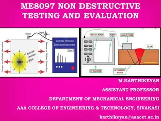
  • 3. INSPECTION METHODS 1. PULSE ECHO METHOD 2. THROUGH TRANSMISSION METHOD 3. ANGLE BEAM ULTRASONIC TESTING 4. IMMERSION ULTRASONIC TESTING
  • 5.
  • 6.  A typical UT inspection system consists of several functional units, such as the pulser/receiver, transducer, and display devices.  A pulser/receiver is an electronic device that can produce high voltage electrical pulses.  Driven by the pulser, the transducer generates high frequency ultrasonic energy.  The sound energy is introduced and propagates through the materials in the form of waves.  When there is a discontinuity (such as a crack) in the wave path, part of the energy will be reflected back from the flaw surface.
  • 7.  The reflected wave signal is transformed into an electrical signal by the transducer and is displayed on a screen.  In the applet below, the reflected signal strength is displayed versus the time from signal generation to when a echo was received.  Signal travel time can be directly related to the distance that the signal traveled.  From the signal, information about the reflector location, size, orientation and other features can sometimes be gained.
  • 9.  Through-transmission ultrasonic testing (UT) is used for detection, verification, sizing, and growth rate monitoring of cracks in piping, vessels, cylindrical shapes, and sometimes noncylindrical shapes.  Through-transmission UT is most widely known as a method of inspection in automated immersion testing for detection of laminars in steel or disbonding in composite materials where two opposite and parallel surfaces can be used for scanning  Through-transmission UT is a two transducer technique in a pitch-catch arrangement.  While there are many types of UT techniques, because of the wide variety of component shapes, sizes, and orientations it is sometimes valuable to have an alternative technique for verification, such as through-transmission
  • 10. The advantages of through transmission are:  Less attenuation of sound energy  No probe ringing  No dead zone on the screen  The orientation of a defect does not matter in the way that it does on the pulse echo display. The disadvantages are:  The defect cannot be located  The defect cannot be identified  The component surfaces must be parallel  Vertical defects do not show  The process must be automated  There must be access to both sides of the component.
  • 11. In an A scan presentation, the amplitude of vertical indications on the screen represents the: (a) Amount of ultrasonic sound energy returning to the search unit (b) Distance travelled by the search unit (c) Thickness of material being tested (d) Elapsed time since the ultrasonic pulse was generated MCQ - 1
  • 12. An instrument display in which the horizontal base line represents elapsed time and the vertical deflection represents signal amplitudes is called: (a) A scan (b) B scan (c) C scan (d) A time line display MCQ - 2
  • 13. A cross section view of a test piece is produced by which of the following? (a) A scan (b) B scan (c) C scan (d) A time line display MCQ - 3
  • 14. The process of comparing an instrument or device with a standard is called: (a) Angulation (b) Calibration (c) Attenuation (d) Correlation MCQ - 4
  • 15. Which technique would most likely be used to examine a weld, with the weld cap still in place? (a) Through transmission testing (b) Angle beam testing (c) Straight beam testing (d) None of the above MCQ - 5