Downloaded 402 times
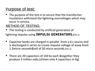
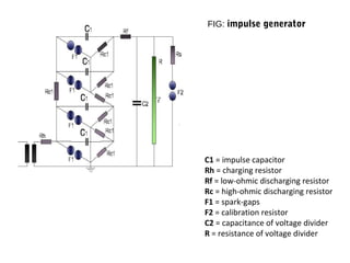
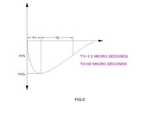


The lightning impulse test assesses transformer insulation's ability to withstand lightning overvoltages, involving the generation of an artificial lightning impulse through capacitors. The negative impulse voltage is applied to the transformer, and the response is analyzed to identify insulation failure. The test is performed on high-voltage windings, ensuring that other terminals and windings are grounded during the process.