SlideShare a Scribd company logo
1 of 7
Download to read offline
International Research Journal of Engineering and Technology (IRJET) e-ISSN: 2395-0056
Volume: 07 Issue: 03 | Mar 2020 www.irjet.net p-ISSN: 2395-0072
© 2020, IRJET | Impact Factor value: 7.34 | ISO 9001:2008 Certified Journal | Page 1343
ASSEMBLYING OF ICF BOGIE SECONDARY SUSPENSION BOLSTER
HANGER PIN LOCK BY USING HYDRAULIC COMPRESS
M. MUGESH1, R. MARIAPPAN2, K. KARTHICK3, M. THIRUKKUMARAN4
1,2,3Department of Mechanical and Automation Engineering, PSN College of Engineering and Technology,
Tirunelveli
4Ass.Professor. Department of Mechanical and Automation Engineering,PSN College of Engineering and
Technology, Tirunelveli
---------------------------------------------------------------------***----------------------------------------------------------------------
Abstract - Secondary suspension which is a part of ICF Bogie assembly process is getting executed. It is done on twosides.For
both the sides weight of 8 tone is moved with the crane from one place to another where the secondary
suspension is processed. There may be a affect with this. In order to avoidthisweusedoubleactingcylinderand3phasemotor
to compress secondary bolster suspension hydraulic and then we connectlowerspringbeamand bogieframe with thehanger.
We could definitely avoid accidents with this.
Key Words: ICF bogie frame, secondary suspension, bolster, BSS hanger pin lock , hydraulic compress,
1. INTRODUCTION
ICF Bogie is a conventional railway bogie used on the majority of Indian Railway main line passenger coaches. The
design of the bogie was developed by ICF (Integral Coach Factory), Perambur, India in collaboration with the Swiss Car &
Elevator Manufacturing Co., Schlieren, Switzerland in the 1950s. The design is also called the Schlieren design based on the
location of the Swiss company
The bogie can be divided into various subsections for easy understanding as follows
A. Bogie Frame
B. Bogie bolster
C. Center pivot pin
D. Wheel set assembly
E. Roller bearing assembly
F. Brake beam assembly
G. Brake levers
H. Brake cylinder
I. Secondary suspension
J. Primary suspension
K. Brake blocks
L. Brake head
Fig 1.1 ICF BOGIE
International Research Journal of Engineering and Technology (IRJET) e-ISSN: 2395-0056
Volume: 07 Issue: 03 | Mar 2020 www.irjet.net p-ISSN: 2395-0072
© 2020, IRJET | Impact Factor value: 7.34 | ISO 9001:2008 Certified Journal | Page 1344
The secondary suspension arrangement of the ICF bogies is through bolster springs. The bogie bolster is not bolted or welded
anywhere to the bogie frame. It is attached to the bogie frame through the anchor link. The anchor link is a tubular structure
with cylindrical housing on both the ends. The cylindrical housings havesilentblocksplacedinthem. Theanchorlink isfixedto
the bogie bolster and the bogie frame with the help of steel brackets welded to the bogie bolster and the bogie frame. Both the
ends of the anchor link act as a hinge and allow movement of the bogie bolster when the coach is moving on a curved track.
1.1SECONDARY SUSPENSION PARTS
 Bolster
 spring beam
 Bolster compression springs
 BSS hangers
 BSS block
 BSS pin
 Equalizing stay rod
 Anchor link
Fig 1.2 SECONDARY SUSPENSION
In secondary suspension system, the bolster is supported on helical coiled springswhichareplacedonlowerspringbeam. The
lower spring beam is suspended from bogie side frame through BSS hangers on BSS hanger blocks. This BSS hanger blocksare
supported on BSS hanger pins which are attached in bogie frame.
Fig 1.3 HANGER PIN LOCK
1.2SECONDARY SUSPENSION BOLSTER
The body bolster is a box type fabricated member made up of channels and weldedtothebodyofthecoach.Itisa free-
floating member. The body bolster transfers the dead weight of the coach body to the bogie frame. There are two type of
bolsters in an ICF bogie: body bolster and the bogie bolster. The body bolster is welded to the coach body whereas the bogie
bolster is a free floating member which takes the entire load of the coach through the body bolster.In body bolster there are 2
side bearers and a center pivot pin are joined by excellent quality welding. These three parts acts as a male part and matches
with the female part welded to bogie bolster. These are very vital parts for smooth running of train
International Research Journal of Engineering and Technology (IRJET) e-ISSN: 2395-0056
Volume: 07 Issue: 03 | Mar 2020 www.irjet.net p-ISSN: 2395-0072
© 2020, IRJET | Impact Factor value: 7.34 | ISO 9001:2008 Certified Journal | Page 1345
Fig 1.4 BOLSTER
1.3THE SECONDARY SUSPENSION LOCKING OF OLD PROCESS IN USE OF NORMAL MASS WEIGHT
The secondary suspension bolster and hanger pin locking system by both side of 8 tone mass weights in used by compress to
spring in both side of locking to the hanger pin lock.The mass weight system compress in one place to another place moved by
use of crane,the over weight crane lift to cut of chain The cut of chain 8 tone mass weight falling accident of railway workers.
The mass weight one place to another place moving systems takingofovertimeinrepairwork andproductionwork wasdelay.
Occupying for more then working place.
1.4BOLSTER COMPRESSION SPRINGS
Since it is a ICF all coiled bogie, helical compression springs are used in secondary suspension system. They are made
up of chrome vanadium/ chrome molybdenumsteel. The mean diameter of bolster springs are approximately 324mm.
Dimensions and safe working load of some bolster springs are given below.
International Research Journal of Engineering and Technology (IRJET) e-ISSN: 2395-0056
Volume: 07 Issue: 03 | Mar 2020 www.irjet.net p-ISSN: 2395-0072
© 2020, IRJET | Impact Factor value: 7.34 | ISO 9001:2008 Certified Journal | Page 1346
Load deflection testing and grouping of Bolster spring
(B.G Main line coaches)
Code Wire
dia
Free
height
Test
Load
Acceptable
height under
test load
Groups as per loaded spring height
A B C
Yellow Oxford Blue
#
Green
B01 42 385 3300 301-317 301-305 306-311 312-317
B03 42 400 4800 291-308 291-296 297-303 304-308
B04 47 400 6100 286-304 286-291 292-297 298-304
B06 36 416 4200 280-299 280-286 287-292 293-299
B11 47
386 6700 306-322 306-311 312-317 318-322
B13 34
B15 40 393
6000 256-272 256-261 262-267 268-272
B16 32.5 286
ICF BOGIE BOLSTER COMPRESS BY USING
2. HYDRAULIC CYLINDER
When diameter of piston rod is almost equal to piston diameter then generally it is called as RAM. But in general all
large size of piston rods are called "RAM". Piston rod is a mechanical member, which transmits kinetic energy, which got
developed at piston, to the work-piece. It is circular in cross-section in case of double action cylinder, as hydraulic sealing is
required between piston rod and guide 50bushIn ram type of single action cylinder, piston rod is also circular in cross action,
while in piston type single action cylinder in which sealing is not required between piston rod and guide bush, piston rod may
be of any type of cross section. For example in case of lock nut type of single action jack, piston rod has thread on its entire
length. Piston-rod is also called as plunger. It could extend from both the end ofcylinder,anditcouldbehollowalso.Piston-rod
could be attached to other component by means of threading, eye bolt type arrangement, or groove and split coupling
arrangement etc
2.1 FRL
It is imperative that a filter, regulator, lubricator (FRL) be employed when running pneumatictools.Theairshouldbe
clean, dry, and lubricated to maximize life and performance of the pneumatic tool. Maximum pressure for the FRL is 120 psi.
FRL Operation
Connect the airlines to the FRL. The direction of the air flow is indicated by arrows on the top of the FRL. With the
pneumatic tool and in the off position, turn on the supply air to the FRL. Check the level of fluids in the clear bowls on the
bottom of the Air Filter and Air Lubricator. If the air filter bowl contains water, drain the bowl by pressing and holding the
small button on the bottom of the bowl until the water is completely drained. Observe the maximum water level line on the
metal protective shield of the bowl. Water can be drained with either the air supply on or off. The oil level in the air lubricator
must be maintained for proper lubrication of the pneumatic tool.The minimum and maximum oil levels are indicated on the
metal protective shield of the oiler bowl. To add oil, remove the black oil plug at the top of the oiler with a ¼” hex wrench, add
International Research Journal of Engineering and Technology (IRJET) e-ISSN: 2395-0056
Volume: 07 Issue: 03 | Mar 2020 www.irjet.net p-ISSN: 2395-0072
© 2020, IRJET | Impact Factor value: 7.34 | ISO 9001:2008 Certified Journal | Page 1347
oil and re-place the plug. USE NONFLUID OIL. Oil can be added with either the air supply on or off. Theair pressureisindicated
on the dial gauge on the front of the Pressure Regulator. To adjustthe air pressures, pull the large black knob below the gauge
down to the unlocked position. When unlocked, an orange band can be observed on the top of the knob Turn the knob clock-
wise to increase the pressure. When the desired pressure is reach push the knob up to the lockedposition.(Theorangebandis
no longer visible.) The amount of lubricant supplied to the pneumatic toolisregulated bythenumberofdropsofoil perminute
and is observed through the site window of the oil adjusting valve knob at the top
2.24/3DIRECTIONALVALVE
Valves of type WM are mechanically, manually operated di-rectional spoolvalves,thoseoftypes WN,WPandWHDare
fluidically operated. They Contro the start, stop and direction oflow. These directional valves basically consist of housing(1),
one actuating element (roller plunger, hand lever, rotary knob) or two actuating elements (hydraulic, pneumatic actuator),
control spool and one or two return springs In the non-operated condition, control spool isheldbyre-turnsprings– inthecase
of rotary knob operation by de-tent in the central or initial position (an exception are im-pulse spools with hydraulic or
pneumatic actuation)actuating elements shift control spool to the desired position.
2.3 PHASE INDUCTION MOTER
Fig 1.5 3PHASE INDUCTION MOTORS
Induction Both motor and transformer work on the principle of induced voltage
Transformer: voltage applied to the primary windings produce an induced voltage in the secondary windings.
Induction motor; voltage applied to the stator windings produce an N induced voltage in the rotor windings.
The difference is that, in the case of the induction motor, the secondary windings can move.
2.4 SECONDRY SUSPENSION COMPRESS BOLSTER HANGER PIN LOCK OLD PROCESS PROBLEM
 The secondary suspension bolster and hanger pin locking system by both side of 8 tone mass weights in used by
compress to spring in both side of locking to the hanger pin lock.
 The mass weight system compress in one place to another place moved byuseofgrane,theoverweightgranelifttocutof
chain
 The cut of chain 8 tone mass weight falling accident of railway workers.
 The mass weight one place to another place moving systems taking of overtimeinrepairwork andproductionwork was
delay.
 Accupying for more then working place.
3. WORKING PROCESS OF HYDRAULIC COMPRESS
The hydraulic compress working of opening valve oil tube going to the tube line of FRL unit .
 The FRL unit in process of filter in the oil.
International Research Journal of Engineering and Technology (IRJET) e-ISSN: 2395-0056
Volume: 07 Issue: 03 | Mar 2020 www.irjet.net p-ISSN: 2395-0072
© 2020, IRJET | Impact Factor value: 7.34 | ISO 9001:2008 Certified Journal | Page 1348
 There are the filter of the frl unit oil going to the 3 phase induction motor ,the 3 phase induction motor recived the oil
and pump of the oil process and pump oil no for a direct, the oil pump for the open for a 4/3 direct control valve in
open for go the oil in tube in inlet line.
 The two inlet tube line down for a hydraulic in compress for a 8 tone weight ,the 8 tone weight in compress of both
side of the hydraulic cylinder .
 The process to easy way for a ICF bogie secondary suspension compress of a spring and easy of lock for a bolster and
locking for a BSS hanger pin lock.
 The method to save for a time and no problem in process.
Fig 1.7 HYDRAULIC COMPRESS SETUP
4. CONCLUSION
From the whole discussion in suspension system, I observe that suspension system is like a white blood cell .Aswhite
blood cell provides energy to our body to fight against diseases or viruses which try to destroy or try todecreaseourlife ,inthe
similar way suspension system provides the energy to a vehicle to protect itself from damaging, increasing life of the vehicle
,increases the handing, increases comfort of passengers and So, accordingtomeifyou removethesuspensionsystem,thenyou
feel like in bull- cart in Audi, Mercedes types luxurious cars. The only difference is speed. So, the scope of SuspensionSystemis
Too Brigh.
REFERENCES
1. I. Sebeşan, Dinamica vehiculelor feroviare (Railway vehicles dynamics), Matrix Rom Publishing House, Bucharest,
2011.
2. T. Mazilu, M. Dumitriu, Tehnologia fabricării si reparării materialului rulant de cale ferată (Technology of railway
rolling stock manufacture and repair), Matrix Rom Publishing House, Bucharest, 2013, ISBN 978-973-755-879-4,
3. R. Talambă, M. Stoica, Osia montată (Wheel set), Bucharest, Publisher ASAB, 2005.
4. M. Uhlig, ESR0330 Wheel defect manual, Engineering standard rolling stock,v.1.2, may 2013.
5. A. H. Wickens, Fundamentals of Rail Vehicle Dynamics: Guidance and Stability. Lisse: Swets & Zeitlinger BV, ISBN 90-
265-1946, 2003.
International Research Journal of Engineering and Technology (IRJET) e-ISSN: 2395-0056
Volume: 07 Issue: 03 | Mar 2020 www.irjet.net p-ISSN: 2395-0072
© 2020, IRJET | Impact Factor value: 7.34 | ISO 9001:2008 Certified Journal | Page 1349
6. D. F. Anania, A. Pena, Innovating CAD-CAM and NC post-machining system for machines tools behavior optimization,
Conference Proceedings of the Academy of Romanian ScientistsPRODUCTICAScientificSession,vol.6,nr1/2014,ISSN
2067-2160.
7. H. B. Kief, H. A. Roschiwal, CNC-Handbuch 2013/14, Carl Hanser Verlag GmbH, 2013, ISBN 978-3-446-43537-7, DOI:
10.3139/9783446437180, 644 pp.
8. EN 15313, Railway applications. In-service wheelset operation requirements. In-service and off-vehicle wheelset
maintenance, 2010.
9. EN 13715, Railway applications. Wheel sets and bogies, Wheels, Tread profile, 2006.

More Related Content

What's hot

Bomag bw138 ac single tandem vibratory roller service repair manual
Bomag bw138 ac single tandem vibratory roller service repair manualBomag bw138 ac single tandem vibratory roller service repair manual
Bomag bw138 ac single tandem vibratory roller service repair manual
pfiskdmjekm
 
linde counterbalance
linde counterbalancelinde counterbalance
linde counterbalance
Aman chawla
 

What's hot (20)

Xe nang toyota
Xe nang toyotaXe nang toyota
Xe nang toyota
 
Jcb 4 dx backhoe loader service repair manual
Jcb 4 dx backhoe loader service repair manualJcb 4 dx backhoe loader service repair manual
Jcb 4 dx backhoe loader service repair manual
 
Hyundai 50 df 7 forklift truck service repair manual
Hyundai 50 df 7 forklift truck service repair manualHyundai 50 df 7 forklift truck service repair manual
Hyundai 50 df 7 forklift truck service repair manual
 
Kubota v3600 t-e3 b diesel engine service repair manual
Kubota v3600 t-e3 b diesel engine service repair manualKubota v3600 t-e3 b diesel engine service repair manual
Kubota v3600 t-e3 b diesel engine service repair manual
 
Xe nâng dầu Yale GP040
Xe nâng dầu Yale GP040Xe nâng dầu Yale GP040
Xe nâng dầu Yale GP040
 
Xe nâng điện ngồi lái CAT 2.5 tấn
Xe nâng điện ngồi lái CAT 2.5 tấnXe nâng điện ngồi lái CAT 2.5 tấn
Xe nâng điện ngồi lái CAT 2.5 tấn
 
Bomag bw138 ac single tandem vibratory roller service repair manual
Bomag bw138 ac single tandem vibratory roller service repair manualBomag bw138 ac single tandem vibratory roller service repair manual
Bomag bw138 ac single tandem vibratory roller service repair manual
 
Xe nâng kho Reach Truck Linde 6.5
Xe nâng kho Reach Truck Linde 6.5Xe nâng kho Reach Truck Linde 6.5
Xe nâng kho Reach Truck Linde 6.5
 
IRJET- Designing and Fabrication of Crash Barrier
IRJET- Designing and Fabrication of Crash BarrierIRJET- Designing and Fabrication of Crash Barrier
IRJET- Designing and Fabrication of Crash Barrier
 
Hyundai hdf15 3 forklift truck service repair manual
Hyundai hdf15 3 forklift truck service repair manualHyundai hdf15 3 forklift truck service repair manual
Hyundai hdf15 3 forklift truck service repair manual
 
Condition Monitoring of Ball Bearing Using Vibration Analysis and Feature Ext...
Condition Monitoring of Ball Bearing Using Vibration Analysis and Feature Ext...Condition Monitoring of Ball Bearing Using Vibration Analysis and Feature Ext...
Condition Monitoring of Ball Bearing Using Vibration Analysis and Feature Ext...
 
Xe nâng điện ngồi lái Toyota 2.8 tấn
Xe nâng điện ngồi lái Toyota 2.8 tấnXe nâng điện ngồi lái Toyota 2.8 tấn
Xe nâng điện ngồi lái Toyota 2.8 tấn
 
Hyundai 50 ds 7e forklift truck service repair manual
Hyundai 50 ds 7e forklift truck service repair manualHyundai 50 ds 7e forklift truck service repair manual
Hyundai 50 ds 7e forklift truck service repair manual
 
Xe nâng điện cũ Toyota 2.5 tấn
Xe nâng điện cũ Toyota 2.5 tấnXe nâng điện cũ Toyota 2.5 tấn
Xe nâng điện cũ Toyota 2.5 tấn
 
Xe nang dien dung lai toyota
Xe nang dien dung lai toyotaXe nang dien dung lai toyota
Xe nang dien dung lai toyota
 
linde counterbalance
linde counterbalancelinde counterbalance
linde counterbalance
 
IRJET- Design and Fabrication of Pneumatic Stirrup Making Machine
IRJET- Design and Fabrication of Pneumatic Stirrup Making MachineIRJET- Design and Fabrication of Pneumatic Stirrup Making Machine
IRJET- Design and Fabrication of Pneumatic Stirrup Making Machine
 
2011 kawasaki ninja 1000 zx1000 hb service repair manual
2011 kawasaki ninja 1000 zx1000 hb service repair manual2011 kawasaki ninja 1000 zx1000 hb service repair manual
2011 kawasaki ninja 1000 zx1000 hb service repair manual
 
2011 kawasaki ninja 1000 zx1000 gb service repair manual
2011 kawasaki ninja 1000 zx1000 gb service repair manual2011 kawasaki ninja 1000 zx1000 gb service repair manual
2011 kawasaki ninja 1000 zx1000 gb service repair manual
 
2012 kawasaki ninja 1000 zx1000 hc service repair manual
2012 kawasaki ninja 1000 zx1000 hc service repair manual2012 kawasaki ninja 1000 zx1000 hc service repair manual
2012 kawasaki ninja 1000 zx1000 hc service repair manual
 

Similar to IRJET - Assemblying of ICF Bogie Secondary Suspension Bolster Hanger Pin Lock by using Hydraulic Compress

Caterpillar Cat 336D L Excavator (Prefix JBF) Service Repair Manual Instant D...
Caterpillar Cat 336D L Excavator (Prefix JBF) Service Repair Manual Instant D...Caterpillar Cat 336D L Excavator (Prefix JBF) Service Repair Manual Instant D...
Caterpillar Cat 336D L Excavator (Prefix JBF) Service Repair Manual Instant D...
zan2736ban
 
Caterpillar Cat 336D L Excavator (Prefix JBF) Service Repair Manual Instant D...
Caterpillar Cat 336D L Excavator (Prefix JBF) Service Repair Manual Instant D...Caterpillar Cat 336D L Excavator (Prefix JBF) Service Repair Manual Instant D...
Caterpillar Cat 336D L Excavator (Prefix JBF) Service Repair Manual Instant D...
ze3xiandiao
 
Caterpillar cat 336 d l excavator (prefix jbf) service repair manual (jbf0000...
Caterpillar cat 336 d l excavator (prefix jbf) service repair manual (jbf0000...Caterpillar cat 336 d l excavator (prefix jbf) service repair manual (jbf0000...
Caterpillar cat 336 d l excavator (prefix jbf) service repair manual (jbf0000...
fjjsekwsxkdmmem
 
Caterpillar cat 336 d l excavator (prefix jbf) service repair manual (jbf0000...
Caterpillar cat 336 d l excavator (prefix jbf) service repair manual (jbf0000...Caterpillar cat 336 d l excavator (prefix jbf) service repair manual (jbf0000...
Caterpillar cat 336 d l excavator (prefix jbf) service repair manual (jbf0000...
fjskkkdmem
 
Caterpillar cat 336 d l excavator (prefix jbf) service repair manual (jbf0000...
Caterpillar cat 336 d l excavator (prefix jbf) service repair manual (jbf0000...Caterpillar cat 336 d l excavator (prefix jbf) service repair manual (jbf0000...
Caterpillar cat 336 d l excavator (prefix jbf) service repair manual (jbf0000...
fjskemdme
 

Similar to IRJET - Assemblying of ICF Bogie Secondary Suspension Bolster Hanger Pin Lock by using Hydraulic Compress (20)

IRJET- Design and Analysis of Lift Arm for Three Point Hitch of Tractor
IRJET- Design and Analysis of Lift Arm for Three Point Hitch of TractorIRJET- Design and Analysis of Lift Arm for Three Point Hitch of Tractor
IRJET- Design and Analysis of Lift Arm for Three Point Hitch of Tractor
 
DESIGN AND FABRICATION OF AUTOMATIC MOTORCYCLE STAND
DESIGN AND FABRICATION OF AUTOMATIC MOTORCYCLE STANDDESIGN AND FABRICATION OF AUTOMATIC MOTORCYCLE STAND
DESIGN AND FABRICATION OF AUTOMATIC MOTORCYCLE STAND
 
IRJET- Design & Development of Hydraulically Dowel Pin Pressing Machine
IRJET- Design & Development of Hydraulically Dowel Pin Pressing MachineIRJET- Design & Development of Hydraulically Dowel Pin Pressing Machine
IRJET- Design & Development of Hydraulically Dowel Pin Pressing Machine
 
IRJET- All Reciprocating Automation in Hydraulic Press
IRJET-  	  All Reciprocating Automation in Hydraulic PressIRJET-  	  All Reciprocating Automation in Hydraulic Press
IRJET- All Reciprocating Automation in Hydraulic Press
 
IRJET- Design and Fabrication of Pneumatic Bumper for Four Wheeler
IRJET- Design and Fabrication of Pneumatic Bumper for Four WheelerIRJET- Design and Fabrication of Pneumatic Bumper for Four Wheeler
IRJET- Design and Fabrication of Pneumatic Bumper for Four Wheeler
 
IRJET -Fabrication of Pneumatic Sheet Metal Shearing Machine
IRJET -Fabrication of Pneumatic Sheet Metal Shearing MachineIRJET -Fabrication of Pneumatic Sheet Metal Shearing Machine
IRJET -Fabrication of Pneumatic Sheet Metal Shearing Machine
 
IRJET- Pneumatic and Electric Energy Generation using Spring Back Mechanism
IRJET-  	  Pneumatic and Electric Energy Generation using Spring Back MechanismIRJET-  	  Pneumatic and Electric Energy Generation using Spring Back Mechanism
IRJET- Pneumatic and Electric Energy Generation using Spring Back Mechanism
 
IRJET- Semi-Automatic Ceramic Sleeve Surface Finishing Machine
IRJET- Semi-Automatic Ceramic Sleeve Surface Finishing MachineIRJET- Semi-Automatic Ceramic Sleeve Surface Finishing Machine
IRJET- Semi-Automatic Ceramic Sleeve Surface Finishing Machine
 
Automatic Tire Inflation System
Automatic Tire Inflation SystemAutomatic Tire Inflation System
Automatic Tire Inflation System
 
IRJET- Operating Mechanism and Design of Hydraulic Scissor Lift
IRJET-  	  Operating Mechanism and Design of Hydraulic Scissor LiftIRJET-  	  Operating Mechanism and Design of Hydraulic Scissor Lift
IRJET- Operating Mechanism and Design of Hydraulic Scissor Lift
 
Caterpillar Cat 336D L Excavator (Prefix JBF) Service Repair Manual Instant D...
Caterpillar Cat 336D L Excavator (Prefix JBF) Service Repair Manual Instant D...Caterpillar Cat 336D L Excavator (Prefix JBF) Service Repair Manual Instant D...
Caterpillar Cat 336D L Excavator (Prefix JBF) Service Repair Manual Instant D...
 
Caterpillar Cat 336D L Excavator (Prefix JBF) Service Repair Manual Instant D...
Caterpillar Cat 336D L Excavator (Prefix JBF) Service Repair Manual Instant D...Caterpillar Cat 336D L Excavator (Prefix JBF) Service Repair Manual Instant D...
Caterpillar Cat 336D L Excavator (Prefix JBF) Service Repair Manual Instant D...
 
Caterpillar cat 336 d l excavator (prefix jbf) service repair manual (jbf0000...
Caterpillar cat 336 d l excavator (prefix jbf) service repair manual (jbf0000...Caterpillar cat 336 d l excavator (prefix jbf) service repair manual (jbf0000...
Caterpillar cat 336 d l excavator (prefix jbf) service repair manual (jbf0000...
 
Caterpillar cat 336 d l excavator (prefix jbf) service repair manual (jbf0000...
Caterpillar cat 336 d l excavator (prefix jbf) service repair manual (jbf0000...Caterpillar cat 336 d l excavator (prefix jbf) service repair manual (jbf0000...
Caterpillar cat 336 d l excavator (prefix jbf) service repair manual (jbf0000...
 
IRJET- Design and Analysis of a Brake Caliper
IRJET- Design and Analysis of a Brake CaliperIRJET- Design and Analysis of a Brake Caliper
IRJET- Design and Analysis of a Brake Caliper
 
IRJET- Pneumatic Conveyer with Bottle Filling and Placing Machine
IRJET-  	  Pneumatic Conveyer with Bottle Filling and Placing MachineIRJET-  	  Pneumatic Conveyer with Bottle Filling and Placing Machine
IRJET- Pneumatic Conveyer with Bottle Filling and Placing Machine
 

More from IRJET Journal

More from IRJET Journal (20)

TUNNELING IN HIMALAYAS WITH NATM METHOD: A SPECIAL REFERENCES TO SUNGAL TUNNE...
TUNNELING IN HIMALAYAS WITH NATM METHOD: A SPECIAL REFERENCES TO SUNGAL TUNNE...TUNNELING IN HIMALAYAS WITH NATM METHOD: A SPECIAL REFERENCES TO SUNGAL TUNNE...
TUNNELING IN HIMALAYAS WITH NATM METHOD: A SPECIAL REFERENCES TO SUNGAL TUNNE...
 
STUDY THE EFFECT OF RESPONSE REDUCTION FACTOR ON RC FRAMED STRUCTURE
STUDY THE EFFECT OF RESPONSE REDUCTION FACTOR ON RC FRAMED STRUCTURESTUDY THE EFFECT OF RESPONSE REDUCTION FACTOR ON RC FRAMED STRUCTURE
STUDY THE EFFECT OF RESPONSE REDUCTION FACTOR ON RC FRAMED STRUCTURE
 
A COMPARATIVE ANALYSIS OF RCC ELEMENT OF SLAB WITH STARK STEEL (HYSD STEEL) A...
A COMPARATIVE ANALYSIS OF RCC ELEMENT OF SLAB WITH STARK STEEL (HYSD STEEL) A...A COMPARATIVE ANALYSIS OF RCC ELEMENT OF SLAB WITH STARK STEEL (HYSD STEEL) A...
A COMPARATIVE ANALYSIS OF RCC ELEMENT OF SLAB WITH STARK STEEL (HYSD STEEL) A...
 
Effect of Camber and Angles of Attack on Airfoil Characteristics
Effect of Camber and Angles of Attack on Airfoil CharacteristicsEffect of Camber and Angles of Attack on Airfoil Characteristics
Effect of Camber and Angles of Attack on Airfoil Characteristics
 
A Review on the Progress and Challenges of Aluminum-Based Metal Matrix Compos...
A Review on the Progress and Challenges of Aluminum-Based Metal Matrix Compos...A Review on the Progress and Challenges of Aluminum-Based Metal Matrix Compos...
A Review on the Progress and Challenges of Aluminum-Based Metal Matrix Compos...
 
Dynamic Urban Transit Optimization: A Graph Neural Network Approach for Real-...
Dynamic Urban Transit Optimization: A Graph Neural Network Approach for Real-...Dynamic Urban Transit Optimization: A Graph Neural Network Approach for Real-...
Dynamic Urban Transit Optimization: A Graph Neural Network Approach for Real-...
 
Structural Analysis and Design of Multi-Storey Symmetric and Asymmetric Shape...
Structural Analysis and Design of Multi-Storey Symmetric and Asymmetric Shape...Structural Analysis and Design of Multi-Storey Symmetric and Asymmetric Shape...
Structural Analysis and Design of Multi-Storey Symmetric and Asymmetric Shape...
 
A Review of “Seismic Response of RC Structures Having Plan and Vertical Irreg...
A Review of “Seismic Response of RC Structures Having Plan and Vertical Irreg...A Review of “Seismic Response of RC Structures Having Plan and Vertical Irreg...
A Review of “Seismic Response of RC Structures Having Plan and Vertical Irreg...
 
A REVIEW ON MACHINE LEARNING IN ADAS
A REVIEW ON MACHINE LEARNING IN ADASA REVIEW ON MACHINE LEARNING IN ADAS
A REVIEW ON MACHINE LEARNING IN ADAS
 
Long Term Trend Analysis of Precipitation and Temperature for Asosa district,...
Long Term Trend Analysis of Precipitation and Temperature for Asosa district,...Long Term Trend Analysis of Precipitation and Temperature for Asosa district,...
Long Term Trend Analysis of Precipitation and Temperature for Asosa district,...
 
P.E.B. Framed Structure Design and Analysis Using STAAD Pro
P.E.B. Framed Structure Design and Analysis Using STAAD ProP.E.B. Framed Structure Design and Analysis Using STAAD Pro
P.E.B. Framed Structure Design and Analysis Using STAAD Pro
 
A Review on Innovative Fiber Integration for Enhanced Reinforcement of Concre...
A Review on Innovative Fiber Integration for Enhanced Reinforcement of Concre...A Review on Innovative Fiber Integration for Enhanced Reinforcement of Concre...
A Review on Innovative Fiber Integration for Enhanced Reinforcement of Concre...
 
Survey Paper on Cloud-Based Secured Healthcare System
Survey Paper on Cloud-Based Secured Healthcare SystemSurvey Paper on Cloud-Based Secured Healthcare System
Survey Paper on Cloud-Based Secured Healthcare System
 
Review on studies and research on widening of existing concrete bridges
Review on studies and research on widening of existing concrete bridgesReview on studies and research on widening of existing concrete bridges
Review on studies and research on widening of existing concrete bridges
 
React based fullstack edtech web application
React based fullstack edtech web applicationReact based fullstack edtech web application
React based fullstack edtech web application
 
A Comprehensive Review of Integrating IoT and Blockchain Technologies in the ...
A Comprehensive Review of Integrating IoT and Blockchain Technologies in the ...A Comprehensive Review of Integrating IoT and Blockchain Technologies in the ...
A Comprehensive Review of Integrating IoT and Blockchain Technologies in the ...
 
A REVIEW ON THE PERFORMANCE OF COCONUT FIBRE REINFORCED CONCRETE.
A REVIEW ON THE PERFORMANCE OF COCONUT FIBRE REINFORCED CONCRETE.A REVIEW ON THE PERFORMANCE OF COCONUT FIBRE REINFORCED CONCRETE.
A REVIEW ON THE PERFORMANCE OF COCONUT FIBRE REINFORCED CONCRETE.
 
Optimizing Business Management Process Workflows: The Dynamic Influence of Mi...
Optimizing Business Management Process Workflows: The Dynamic Influence of Mi...Optimizing Business Management Process Workflows: The Dynamic Influence of Mi...
Optimizing Business Management Process Workflows: The Dynamic Influence of Mi...
 
Multistoried and Multi Bay Steel Building Frame by using Seismic Design
Multistoried and Multi Bay Steel Building Frame by using Seismic DesignMultistoried and Multi Bay Steel Building Frame by using Seismic Design
Multistoried and Multi Bay Steel Building Frame by using Seismic Design
 
Cost Optimization of Construction Using Plastic Waste as a Sustainable Constr...
Cost Optimization of Construction Using Plastic Waste as a Sustainable Constr...Cost Optimization of Construction Using Plastic Waste as a Sustainable Constr...
Cost Optimization of Construction Using Plastic Waste as a Sustainable Constr...
 

Recently uploaded

Call Girls in South Ex (delhi) call me [🔝9953056974🔝] escort service 24X7
Call Girls in South Ex (delhi) call me [🔝9953056974🔝] escort service 24X7Call Girls in South Ex (delhi) call me [🔝9953056974🔝] escort service 24X7
Call Girls in South Ex (delhi) call me [🔝9953056974🔝] escort service 24X7
9953056974 Low Rate Call Girls In Saket, Delhi NCR
 
Integrated Test Rig For HTFE-25 - Neometrix
Integrated Test Rig For HTFE-25 - NeometrixIntegrated Test Rig For HTFE-25 - Neometrix
Integrated Test Rig For HTFE-25 - Neometrix
Neometrix_Engineering_Pvt_Ltd
 
XXXXXXXXXXXXXXXXXXXXXXXXXXXXXXXXXXXXXXXXXXXXXXXXXXXX
XXXXXXXXXXXXXXXXXXXXXXXXXXXXXXXXXXXXXXXXXXXXXXXXXXXXXXXXXXXXXXXXXXXXXXXXXXXXXXXXXXXXXXXXXXXXXXXXXXXXXXXX
XXXXXXXXXXXXXXXXXXXXXXXXXXXXXXXXXXXXXXXXXXXXXXXXXXXX
ssuser89054b
 

Recently uploaded (20)

Navigating Complexity: The Role of Trusted Partners and VIAS3D in Dassault Sy...
Navigating Complexity: The Role of Trusted Partners and VIAS3D in Dassault Sy...Navigating Complexity: The Role of Trusted Partners and VIAS3D in Dassault Sy...
Navigating Complexity: The Role of Trusted Partners and VIAS3D in Dassault Sy...
 
Signal Processing and Linear System Analysis
Signal Processing and Linear System AnalysisSignal Processing and Linear System Analysis
Signal Processing and Linear System Analysis
 
Hostel management system project report..pdf
Hostel management system project report..pdfHostel management system project report..pdf
Hostel management system project report..pdf
 
Electromagnetic relays used for power system .pptx
Electromagnetic relays used for power system .pptxElectromagnetic relays used for power system .pptx
Electromagnetic relays used for power system .pptx
 
Call Girls in South Ex (delhi) call me [🔝9953056974🔝] escort service 24X7
Call Girls in South Ex (delhi) call me [🔝9953056974🔝] escort service 24X7Call Girls in South Ex (delhi) call me [🔝9953056974🔝] escort service 24X7
Call Girls in South Ex (delhi) call me [🔝9953056974🔝] escort service 24X7
 
💚Trustworthy Call Girls Pune Call Girls Service Just Call 🍑👄6378878445 🍑👄 Top...
💚Trustworthy Call Girls Pune Call Girls Service Just Call 🍑👄6378878445 🍑👄 Top...💚Trustworthy Call Girls Pune Call Girls Service Just Call 🍑👄6378878445 🍑👄 Top...
💚Trustworthy Call Girls Pune Call Girls Service Just Call 🍑👄6378878445 🍑👄 Top...
 
S1S2 B.Arch MGU - HOA1&2 Module 3 -Temple Architecture of Kerala.pptx
S1S2 B.Arch MGU - HOA1&2 Module 3 -Temple Architecture of Kerala.pptxS1S2 B.Arch MGU - HOA1&2 Module 3 -Temple Architecture of Kerala.pptx
S1S2 B.Arch MGU - HOA1&2 Module 3 -Temple Architecture of Kerala.pptx
 
Tamil Call Girls Bhayandar WhatsApp +91-9930687706, Best Service
Tamil Call Girls Bhayandar WhatsApp +91-9930687706, Best ServiceTamil Call Girls Bhayandar WhatsApp +91-9930687706, Best Service
Tamil Call Girls Bhayandar WhatsApp +91-9930687706, Best Service
 
Ground Improvement Technique: Earth Reinforcement
Ground Improvement Technique: Earth ReinforcementGround Improvement Technique: Earth Reinforcement
Ground Improvement Technique: Earth Reinforcement
 
Theory of Time 2024 (Universal Theory for Everything)
Theory of Time 2024 (Universal Theory for Everything)Theory of Time 2024 (Universal Theory for Everything)
Theory of Time 2024 (Universal Theory for Everything)
 
UNIT 4 PTRP final Convergence in probability.pptx
UNIT 4 PTRP final Convergence in probability.pptxUNIT 4 PTRP final Convergence in probability.pptx
UNIT 4 PTRP final Convergence in probability.pptx
 
Integrated Test Rig For HTFE-25 - Neometrix
Integrated Test Rig For HTFE-25 - NeometrixIntegrated Test Rig For HTFE-25 - Neometrix
Integrated Test Rig For HTFE-25 - Neometrix
 
XXXXXXXXXXXXXXXXXXXXXXXXXXXXXXXXXXXXXXXXXXXXXXXXXXXX
XXXXXXXXXXXXXXXXXXXXXXXXXXXXXXXXXXXXXXXXXXXXXXXXXXXXXXXXXXXXXXXXXXXXXXXXXXXXXXXXXXXXXXXXXXXXXXXXXXXXXXXX
XXXXXXXXXXXXXXXXXXXXXXXXXXXXXXXXXXXXXXXXXXXXXXXXXXXX
 
Thermal Engineering-R & A / C - unit - V
Thermal Engineering-R & A / C - unit - VThermal Engineering-R & A / C - unit - V
Thermal Engineering-R & A / C - unit - V
 
Jaipur ❤CALL GIRL 0000000000❤CALL GIRLS IN Jaipur ESCORT SERVICE❤CALL GIRL IN...
Jaipur ❤CALL GIRL 0000000000❤CALL GIRLS IN Jaipur ESCORT SERVICE❤CALL GIRL IN...Jaipur ❤CALL GIRL 0000000000❤CALL GIRLS IN Jaipur ESCORT SERVICE❤CALL GIRL IN...
Jaipur ❤CALL GIRL 0000000000❤CALL GIRLS IN Jaipur ESCORT SERVICE❤CALL GIRL IN...
 
Thermal Engineering Unit - I & II . ppt
Thermal Engineering  Unit - I & II . pptThermal Engineering  Unit - I & II . ppt
Thermal Engineering Unit - I & II . ppt
 
HOA1&2 - Module 3 - PREHISTORCI ARCHITECTURE OF KERALA.pptx
HOA1&2 - Module 3 - PREHISTORCI ARCHITECTURE OF KERALA.pptxHOA1&2 - Module 3 - PREHISTORCI ARCHITECTURE OF KERALA.pptx
HOA1&2 - Module 3 - PREHISTORCI ARCHITECTURE OF KERALA.pptx
 
Introduction to Data Visualization,Matplotlib.pdf
Introduction to Data Visualization,Matplotlib.pdfIntroduction to Data Visualization,Matplotlib.pdf
Introduction to Data Visualization,Matplotlib.pdf
 
FEA Based Level 3 Assessment of Deformed Tanks with Fluid Induced Loads
FEA Based Level 3 Assessment of Deformed Tanks with Fluid Induced LoadsFEA Based Level 3 Assessment of Deformed Tanks with Fluid Induced Loads
FEA Based Level 3 Assessment of Deformed Tanks with Fluid Induced Loads
 
Orlando’s Arnold Palmer Hospital Layout Strategy-1.pptx
Orlando’s Arnold Palmer Hospital Layout Strategy-1.pptxOrlando’s Arnold Palmer Hospital Layout Strategy-1.pptx
Orlando’s Arnold Palmer Hospital Layout Strategy-1.pptx
 

IRJET - Assemblying of ICF Bogie Secondary Suspension Bolster Hanger Pin Lock by using Hydraulic Compress

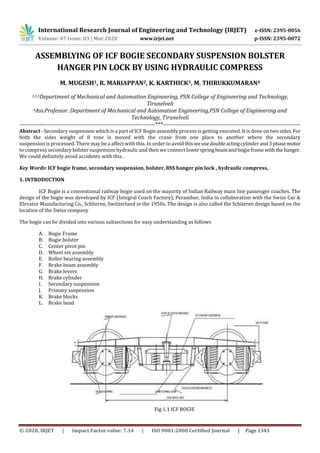
  • 1. International Research Journal of Engineering and Technology (IRJET) e-ISSN: 2395-0056 Volume: 07 Issue: 03 | Mar 2020 www.irjet.net p-ISSN: 2395-0072 © 2020, IRJET | Impact Factor value: 7.34 | ISO 9001:2008 Certified Journal | Page 1343 ASSEMBLYING OF ICF BOGIE SECONDARY SUSPENSION BOLSTER HANGER PIN LOCK BY USING HYDRAULIC COMPRESS M. MUGESH1, R. MARIAPPAN2, K. KARTHICK3, M. THIRUKKUMARAN4 1,2,3Department of Mechanical and Automation Engineering, PSN College of Engineering and Technology, Tirunelveli 4Ass.Professor. Department of Mechanical and Automation Engineering,PSN College of Engineering and Technology, Tirunelveli ---------------------------------------------------------------------***---------------------------------------------------------------------- Abstract - Secondary suspension which is a part of ICF Bogie assembly process is getting executed. It is done on twosides.For both the sides weight of 8 tone is moved with the crane from one place to another where the secondary suspension is processed. There may be a affect with this. In order to avoidthisweusedoubleactingcylinderand3phasemotor to compress secondary bolster suspension hydraulic and then we connectlowerspringbeamand bogieframe with thehanger. We could definitely avoid accidents with this. Key Words: ICF bogie frame, secondary suspension, bolster, BSS hanger pin lock , hydraulic compress, 1. INTRODUCTION ICF Bogie is a conventional railway bogie used on the majority of Indian Railway main line passenger coaches. The design of the bogie was developed by ICF (Integral Coach Factory), Perambur, India in collaboration with the Swiss Car & Elevator Manufacturing Co., Schlieren, Switzerland in the 1950s. The design is also called the Schlieren design based on the location of the Swiss company The bogie can be divided into various subsections for easy understanding as follows A. Bogie Frame B. Bogie bolster C. Center pivot pin D. Wheel set assembly E. Roller bearing assembly F. Brake beam assembly G. Brake levers H. Brake cylinder I. Secondary suspension J. Primary suspension K. Brake blocks L. Brake head Fig 1.1 ICF BOGIE
  • 2. International Research Journal of Engineering and Technology (IRJET) e-ISSN: 2395-0056 Volume: 07 Issue: 03 | Mar 2020 www.irjet.net p-ISSN: 2395-0072 © 2020, IRJET | Impact Factor value: 7.34 | ISO 9001:2008 Certified Journal | Page 1344 The secondary suspension arrangement of the ICF bogies is through bolster springs. The bogie bolster is not bolted or welded anywhere to the bogie frame. It is attached to the bogie frame through the anchor link. The anchor link is a tubular structure with cylindrical housing on both the ends. The cylindrical housings havesilentblocksplacedinthem. Theanchorlink isfixedto the bogie bolster and the bogie frame with the help of steel brackets welded to the bogie bolster and the bogie frame. Both the ends of the anchor link act as a hinge and allow movement of the bogie bolster when the coach is moving on a curved track. 1.1SECONDARY SUSPENSION PARTS  Bolster  spring beam  Bolster compression springs  BSS hangers  BSS block  BSS pin  Equalizing stay rod  Anchor link Fig 1.2 SECONDARY SUSPENSION In secondary suspension system, the bolster is supported on helical coiled springswhichareplacedonlowerspringbeam. The lower spring beam is suspended from bogie side frame through BSS hangers on BSS hanger blocks. This BSS hanger blocksare supported on BSS hanger pins which are attached in bogie frame. Fig 1.3 HANGER PIN LOCK 1.2SECONDARY SUSPENSION BOLSTER The body bolster is a box type fabricated member made up of channels and weldedtothebodyofthecoach.Itisa free- floating member. The body bolster transfers the dead weight of the coach body to the bogie frame. There are two type of bolsters in an ICF bogie: body bolster and the bogie bolster. The body bolster is welded to the coach body whereas the bogie bolster is a free floating member which takes the entire load of the coach through the body bolster.In body bolster there are 2 side bearers and a center pivot pin are joined by excellent quality welding. These three parts acts as a male part and matches with the female part welded to bogie bolster. These are very vital parts for smooth running of train
  • 3. International Research Journal of Engineering and Technology (IRJET) e-ISSN: 2395-0056 Volume: 07 Issue: 03 | Mar 2020 www.irjet.net p-ISSN: 2395-0072 © 2020, IRJET | Impact Factor value: 7.34 | ISO 9001:2008 Certified Journal | Page 1345 Fig 1.4 BOLSTER 1.3THE SECONDARY SUSPENSION LOCKING OF OLD PROCESS IN USE OF NORMAL MASS WEIGHT The secondary suspension bolster and hanger pin locking system by both side of 8 tone mass weights in used by compress to spring in both side of locking to the hanger pin lock.The mass weight system compress in one place to another place moved by use of crane,the over weight crane lift to cut of chain The cut of chain 8 tone mass weight falling accident of railway workers. The mass weight one place to another place moving systems takingofovertimeinrepairwork andproductionwork wasdelay. Occupying for more then working place. 1.4BOLSTER COMPRESSION SPRINGS Since it is a ICF all coiled bogie, helical compression springs are used in secondary suspension system. They are made up of chrome vanadium/ chrome molybdenumsteel. The mean diameter of bolster springs are approximately 324mm. Dimensions and safe working load of some bolster springs are given below.
  • 4. International Research Journal of Engineering and Technology (IRJET) e-ISSN: 2395-0056 Volume: 07 Issue: 03 | Mar 2020 www.irjet.net p-ISSN: 2395-0072 © 2020, IRJET | Impact Factor value: 7.34 | ISO 9001:2008 Certified Journal | Page 1346 Load deflection testing and grouping of Bolster spring (B.G Main line coaches) Code Wire dia Free height Test Load Acceptable height under test load Groups as per loaded spring height A B C Yellow Oxford Blue # Green B01 42 385 3300 301-317 301-305 306-311 312-317 B03 42 400 4800 291-308 291-296 297-303 304-308 B04 47 400 6100 286-304 286-291 292-297 298-304 B06 36 416 4200 280-299 280-286 287-292 293-299 B11 47 386 6700 306-322 306-311 312-317 318-322 B13 34 B15 40 393 6000 256-272 256-261 262-267 268-272 B16 32.5 286 ICF BOGIE BOLSTER COMPRESS BY USING 2. HYDRAULIC CYLINDER When diameter of piston rod is almost equal to piston diameter then generally it is called as RAM. But in general all large size of piston rods are called "RAM". Piston rod is a mechanical member, which transmits kinetic energy, which got developed at piston, to the work-piece. It is circular in cross-section in case of double action cylinder, as hydraulic sealing is required between piston rod and guide 50bushIn ram type of single action cylinder, piston rod is also circular in cross action, while in piston type single action cylinder in which sealing is not required between piston rod and guide bush, piston rod may be of any type of cross section. For example in case of lock nut type of single action jack, piston rod has thread on its entire length. Piston-rod is also called as plunger. It could extend from both the end ofcylinder,anditcouldbehollowalso.Piston-rod could be attached to other component by means of threading, eye bolt type arrangement, or groove and split coupling arrangement etc 2.1 FRL It is imperative that a filter, regulator, lubricator (FRL) be employed when running pneumatictools.Theairshouldbe clean, dry, and lubricated to maximize life and performance of the pneumatic tool. Maximum pressure for the FRL is 120 psi. FRL Operation Connect the airlines to the FRL. The direction of the air flow is indicated by arrows on the top of the FRL. With the pneumatic tool and in the off position, turn on the supply air to the FRL. Check the level of fluids in the clear bowls on the bottom of the Air Filter and Air Lubricator. If the air filter bowl contains water, drain the bowl by pressing and holding the small button on the bottom of the bowl until the water is completely drained. Observe the maximum water level line on the metal protective shield of the bowl. Water can be drained with either the air supply on or off. The oil level in the air lubricator must be maintained for proper lubrication of the pneumatic tool.The minimum and maximum oil levels are indicated on the metal protective shield of the oiler bowl. To add oil, remove the black oil plug at the top of the oiler with a ¼” hex wrench, add
  • 5. International Research Journal of Engineering and Technology (IRJET) e-ISSN: 2395-0056 Volume: 07 Issue: 03 | Mar 2020 www.irjet.net p-ISSN: 2395-0072 © 2020, IRJET | Impact Factor value: 7.34 | ISO 9001:2008 Certified Journal | Page 1347 oil and re-place the plug. USE NONFLUID OIL. Oil can be added with either the air supply on or off. Theair pressureisindicated on the dial gauge on the front of the Pressure Regulator. To adjustthe air pressures, pull the large black knob below the gauge down to the unlocked position. When unlocked, an orange band can be observed on the top of the knob Turn the knob clock- wise to increase the pressure. When the desired pressure is reach push the knob up to the lockedposition.(Theorangebandis no longer visible.) The amount of lubricant supplied to the pneumatic toolisregulated bythenumberofdropsofoil perminute and is observed through the site window of the oil adjusting valve knob at the top 2.24/3DIRECTIONALVALVE Valves of type WM are mechanically, manually operated di-rectional spoolvalves,thoseoftypes WN,WPandWHDare fluidically operated. They Contro the start, stop and direction oflow. These directional valves basically consist of housing(1), one actuating element (roller plunger, hand lever, rotary knob) or two actuating elements (hydraulic, pneumatic actuator), control spool and one or two return springs In the non-operated condition, control spool isheldbyre-turnsprings– inthecase of rotary knob operation by de-tent in the central or initial position (an exception are im-pulse spools with hydraulic or pneumatic actuation)actuating elements shift control spool to the desired position. 2.3 PHASE INDUCTION MOTER Fig 1.5 3PHASE INDUCTION MOTORS Induction Both motor and transformer work on the principle of induced voltage Transformer: voltage applied to the primary windings produce an induced voltage in the secondary windings. Induction motor; voltage applied to the stator windings produce an N induced voltage in the rotor windings. The difference is that, in the case of the induction motor, the secondary windings can move. 2.4 SECONDRY SUSPENSION COMPRESS BOLSTER HANGER PIN LOCK OLD PROCESS PROBLEM  The secondary suspension bolster and hanger pin locking system by both side of 8 tone mass weights in used by compress to spring in both side of locking to the hanger pin lock.  The mass weight system compress in one place to another place moved byuseofgrane,theoverweightgranelifttocutof chain  The cut of chain 8 tone mass weight falling accident of railway workers.  The mass weight one place to another place moving systems taking of overtimeinrepairwork andproductionwork was delay.  Accupying for more then working place. 3. WORKING PROCESS OF HYDRAULIC COMPRESS The hydraulic compress working of opening valve oil tube going to the tube line of FRL unit .  The FRL unit in process of filter in the oil.
  • 6. International Research Journal of Engineering and Technology (IRJET) e-ISSN: 2395-0056 Volume: 07 Issue: 03 | Mar 2020 www.irjet.net p-ISSN: 2395-0072 © 2020, IRJET | Impact Factor value: 7.34 | ISO 9001:2008 Certified Journal | Page 1348  There are the filter of the frl unit oil going to the 3 phase induction motor ,the 3 phase induction motor recived the oil and pump of the oil process and pump oil no for a direct, the oil pump for the open for a 4/3 direct control valve in open for go the oil in tube in inlet line.  The two inlet tube line down for a hydraulic in compress for a 8 tone weight ,the 8 tone weight in compress of both side of the hydraulic cylinder .  The process to easy way for a ICF bogie secondary suspension compress of a spring and easy of lock for a bolster and locking for a BSS hanger pin lock.  The method to save for a time and no problem in process. Fig 1.7 HYDRAULIC COMPRESS SETUP 4. CONCLUSION From the whole discussion in suspension system, I observe that suspension system is like a white blood cell .Aswhite blood cell provides energy to our body to fight against diseases or viruses which try to destroy or try todecreaseourlife ,inthe similar way suspension system provides the energy to a vehicle to protect itself from damaging, increasing life of the vehicle ,increases the handing, increases comfort of passengers and So, accordingtomeifyou removethesuspensionsystem,thenyou feel like in bull- cart in Audi, Mercedes types luxurious cars. The only difference is speed. So, the scope of SuspensionSystemis Too Brigh. REFERENCES 1. I. Sebeşan, Dinamica vehiculelor feroviare (Railway vehicles dynamics), Matrix Rom Publishing House, Bucharest, 2011. 2. T. Mazilu, M. Dumitriu, Tehnologia fabricării si reparării materialului rulant de cale ferată (Technology of railway rolling stock manufacture and repair), Matrix Rom Publishing House, Bucharest, 2013, ISBN 978-973-755-879-4, 3. R. Talambă, M. Stoica, Osia montată (Wheel set), Bucharest, Publisher ASAB, 2005. 4. M. Uhlig, ESR0330 Wheel defect manual, Engineering standard rolling stock,v.1.2, may 2013. 5. A. H. Wickens, Fundamentals of Rail Vehicle Dynamics: Guidance and Stability. Lisse: Swets & Zeitlinger BV, ISBN 90- 265-1946, 2003.
  • 7. International Research Journal of Engineering and Technology (IRJET) e-ISSN: 2395-0056 Volume: 07 Issue: 03 | Mar 2020 www.irjet.net p-ISSN: 2395-0072 © 2020, IRJET | Impact Factor value: 7.34 | ISO 9001:2008 Certified Journal | Page 1349 6. D. F. Anania, A. Pena, Innovating CAD-CAM and NC post-machining system for machines tools behavior optimization, Conference Proceedings of the Academy of Romanian ScientistsPRODUCTICAScientificSession,vol.6,nr1/2014,ISSN 2067-2160. 7. H. B. Kief, H. A. Roschiwal, CNC-Handbuch 2013/14, Carl Hanser Verlag GmbH, 2013, ISBN 978-3-446-43537-7, DOI: 10.3139/9783446437180, 644 pp. 8. EN 15313, Railway applications. In-service wheelset operation requirements. In-service and off-vehicle wheelset maintenance, 2010. 9. EN 13715, Railway applications. Wheel sets and bogies, Wheels, Tread profile, 2006.