Extendable additional steps for busses and trucks
•
0 likes•2 views

https://www.irjet.net/archives/V10/i8/IRJET-V10I8136.pdf

Recommended
Recommended
More Related Content
Similar to Extendable additional steps for busses and trucks
Similar to Extendable additional steps for busses and trucks (20)
More from IRJET Journal
More from IRJET Journal (20)
Recently uploaded
Recently uploaded (20)
Extendable additional steps for busses and trucks
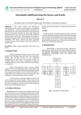
- 1. International Research Journal of Engineering and Technology (IRJET) e-ISSN: 2395-0056 Volume: 10 Issue: 08 | Aug 2023 www.irjet.net p-ISSN: 2395-0072 © 2023, IRJET | Impact Factor value: 8.226 | ISO 9001:2008 Certified Journal | Page 820 Extendable additional steps for busses and trucks Dharun T1 1UG Student, Dept. of Production Engineering, PSG College of Technology, Coimbatore. ---------------------------------------------------------------------***--------------------------------------------------------------------- Abstract - The Product Design and Development Laboratory is for the students to gain experience in designing and developing a product from feasibility assessment to development. As a part of this laboratory, I have generated ideas and conceptual sketches for these ideas. Using the weighted matrix, I have selected the “Extendable additional steps for busses and trucks”. The design for the product is finalized using Pugh matrix and CAD modelsarecreatedusing SolidWorks. This report contains the ideas generated, conceptual design, product design and the CAD model for the finalized idea. Key Words: Design, analysis, pneumatic, Steel, busses and trucks 1.INTRODUCTION Public transportation plays a major role in many people’s life. With high steps, bus rides are not smooth for elderly. The low-floor busses are not completely implemented in Tamil Nadu. The low-floor busses are available only on the semi-air conditioned or fully air- conditioned busses such asVolvoandDaimler but thetickets are expensive. While using high-floor steps in busses, elderly people have the risk of getting knee pain. Also, while using high-floor steps everyonehasthechanceofgettingkneepain by carrying heavy weight. And for children this will be a tough task to do. The ground clearance between the steps and height of all individual steps makes it harder. For this problem, extendable additional stepscanbe used to reduce the found clearance. These steps can be extracted and retracted. This additional step can reduce the knee pain as people do not have to strain while landing on the ground and boarding the busses 1.1 Problem definition With high steps, bus rides are not smooth for elderly. The low-floor busses are not completely implemented in Tamil Nadu. The low-floor busses are available only onthesemi-air conditioned or fully air-conditionedbussessuchasVolvoand Daimler but the tickets are expensive. While using high-floor steps in busses, elderly people have the risk of getting knee pain. Also, while using high-floor steps everyone has the chance of gettingknee pain by carryingheavyweight.Andfor the children this will be a tough task. The ground clearance between the steps and height of all individual steps makes it harder. 1.2 Aim For this problem, extendable additional steps can beused to reduce the ground clearance. Thesestepscanbe extracted and retracted. These additional steps can reduce the knee pain as people do not have to stain while landing on the ground and boarding the busses. Thesewill be retractedsoit will not be a disturbance in the side. 2. METHODOLOGY Methodology is specific procedures followed to identify, select, analyze the process and completetheproject. The following methodology is carried for completing the EXTENDABLE ADDITIONAL STEPS FOR BUSSES AND TRUCKS project. Fig - 1: Flowchart of methodology
- 2. International Research Journal of Engineering and Technology (IRJET) e-ISSN: 2395-0056 Volume: 10 Issue: 08 | Aug 2023 www.irjet.net p-ISSN: 2395-0072 © 2023, IRJET | Impact Factor value: 8.226 | ISO 9001:2008 Certified Journal | Page 821 Fig - 2: Cause and effect diagram Fig - 3: Hierarchical Task Analysis 3. DESIGN Based on the requirement andconsideringvariousdesign factor the conceptualsketcheswerecreatedandfinalizedone design among the conceptual sketch. The dimensions are adapted based on Indian Anthropometric dimension data. The dimensions such as weight of the person were determined with the help of the anthropometric data. Irjet templatesample paragraph, Irjettemplatesampleparagraph .Irjet template sample paragraph. Irjet template sample paragraph. 3.1 Factors considered for Design 3.1.1 Indian Anthropometric Data Anthropometric data are data of human body size andshape. The core element is weight. 3.1.2 Design Calculation Fig - 4: Design calculation Fig - 5: Design calculation
- 3. International Research Journal of Engineering and Technology (IRJET) e-ISSN: 2395-0056 Volume: 10 Issue: 08 | Aug 2023 www.irjet.net p-ISSN: 2395-0072 © 2023, IRJET | Impact Factor value: 8.226 | ISO 9001:2008 Certified Journal | Page 822 3.2 CADD Model Fig - 6: Components (a-j) The components of the extendable steps assembly are shown in the above figures from a to j. Listing base frame, cylinder,link 1, link 2, link 3,step, piston, pin 1, pin 2, andpin 3. 3.3 CADD Assembly Fig -7: Final assembly 1st view Fig - 8: Final assembly 2nd view Fig - 9: Final assembly 3rd view b a h d c g f e j i
- 4. International Research Journal of Engineering and Technology (IRJET) e-ISSN: 2395-0056 Volume: 10 Issue: 08 | Aug 2023 www.irjet.net p-ISSN: 2395-0072 © 2023, IRJET | Impact Factor value: 8.226 | ISO 9001:2008 Certified Journal | Page 823 3.4. Bill of Materials Table -1: Bill of Materials Item number Part name Material Qua ntit y 1 Link 1 Steel 2 2 Link 2 Steel 2 3 Link 3 Steel 4 4 Step Mild steel 2 5 Piston Stainless steel 2 6 Cylinder Stainless steel 2 7 Base frame Mild steel 1 8 Pin 1 Steel 2 9 Pin 2 Steel 4 3.5 Parts The product shown intheassembledmodel consists of eight major parts: base frame, link, step, piston, and cylinder Base frame: The base frame supportsall otherpartsanditis connected to the bus. Link: The link helps in connecting the steps with the frame. Piston: Piston is the part of double acting cylinder. Cylinder: The cylinder is the double acting cylinder’s body. Step: The step is a rectangular part and it is themajorpartof this assembly 4. STATIC STRUCTURAL ANALYSIS A static structural analysis determines the stresses, strains, displacements, and forces in structures or components or products caused by loads that do not induce significant inertia and damping effects. The model is imported as iges file into the Ansys software. The above are the boundary conditions applied to the model in Ansys software. Coarse mesh structure type with a size of 5mm is used for generating mesh for the model. The model is solved and the results are obtained. 4.1 Material properties Table -2: Material properties Part Material Young’s Modulus (GPa) Density (Kg/m^3) Step M.S 210 7850 Link M.S 210 7850 Pins S. S 210 7850 Base frame M.S 210 7850 Cylinder S. S 190 7860 Piston S. S 190 7860 4.2 Material selection using Ashby chart Fig - 10: Material selection using Ashby chart 4.3 Analysis 4.3.2 Analysis of first step Fig - 11: Total deformation The maximum total deformation 2.0589e-12mmandthe minimum total deformation was 0 mm.
- 5. International Research Journal of Engineering and Technology (IRJET) e-ISSN: 2395-0056 Volume: 10 Issue: 08 | Aug 2023 www.irjet.net p-ISSN: 2395-0072 © 2023, IRJET | Impact Factor value: 8.226 | ISO 9001:2008 Certified Journal | Page 824 Fig - 12: Equivalent stress The maximum equivalent stress was 5.0545e-9 MPa and the minimum equivalent stress was 0 MPa. Fig - 13 Equivalent elastic stress The maximum equivalent elastic stress was 2.6075e-16 mm/mm and the minimum equivalent elastic stress was 0 mm/mm. 4.3.3 Analysis of second step Fig - 14: Total deformation The maximum total deformation 1.4709e-11 mm and the minimum total deformation was 0 Fig - 15: Equivalent stress The maximum equivalentstresswas7.9284e-11MPaand the minimum equivalent stress was 0 MPa. Fig - 16: Equivalent elastic stress The maximum equivalent elastic stress was 4.1105e-21 mm/mm and the minimum equivalent elastic stress was 0 mm/mm. 5. DRAWING (2D) Fig - 17: Assembly
- 6. International Research Journal of Engineering and Technology (IRJET) e-ISSN: 2395-0056 Volume: 10 Issue: 08 | Aug 2023 www.irjet.net p-ISSN: 2395-0072 © 2023, IRJET | Impact Factor value: 8.226 | ISO 9001:2008 Certified Journal | Page 825 6. CONCLUSIONS During analysis the project is tested on total deformation, equivalent stress and equivalent elastic stress, modelling and analysis done by using PTC Creo, and Ansys. And the results were within the specification limits defined by automotive standards from Automotive industry standards committee. REFERENCES [1] John Pucher, “Urban public transport in India: Trends, challenges and innovation,” ResearchGate March 2004, [2] Ramu Inala, “Static analysis of an isotropic rectangular plate using finite elementanalysis(FEA)”,ResearchGate, 2012. [3] Imo, “Transportation Patterns and Problems of People with Disabilities,” National library of medicine, 2004. [4] Jakun Korta, “Multi-material design optimization of a bus body structure,” ResearchGate January 2013. [5] M. Jimenez, “Experimental study of double-acting pneumatic cylinders”, ResearchGate, February 2020. [6] Imo, “Impact and corrosion behavior of mild steel”, Engineering Science and Technology, an International Journal, May 2020. [7] Ramu Inala, “Static analysis of an isotropic rectangular plate using finite elementanalysis(FEA)”,ResearchGate, January 2012. [8] John Pucher, Nisha Korattyswaroopam, “The Crisis of Public Transport in India: Overwhelming Needs but Limited Resources”, University of Southern Florida, 2014. [9] Ramu Inala, “Vehicle body engineering”, Blogspot, September 2015. [10] Automotive industry standards committee, “The automotive research association of India”, Automotive industry standard, May 2017. [11] Dr. Debkumar Chakarabarthi, “Indian Anthropometric Dimension for Ergonomic Design Practice, National Institute of Design”, First Published April 1, 1999 ISBN 81-86199-15-0. BIOGRAPHY Motivated project management professional passionateinbringing ideas to life. Proficient in project management, lean methodology, supply chain management and data analytics. Enjoys finding creative solutions in improving productivity.