SlideShare a Scribd company logo
1 of 8
Download to read offline
International Research Journal of Engineering and Technology (IRJET) e-ISSN: 2395-0056
Volume: 04 Issue: 10 | Oct -2017 www.irjet.net p-ISSN: 2395-0072
© 2017, IRJET | Impact Factor value: 5.181 | ISO 9001:2008 Certified Journal | Page 717
COMPARATIVE STUDY OF H-BRIDGE MULTI LEVEL INVERTERS
S.Srinivasa Rao1, Dr. CH. V. V. S. Bhaskara Reddy2
1PG Student, A.U. College of Engineering (A), Dept. Electrical Engg., A.P, India
2Professor, A.U. College of Engineering (A), Dept. Electrical Engg., A.P, India.
---------------------------------------------------------------------***---------------------------------------------------------------------
Abstract - Now a days, usage of the power electronic devices
for conversion of electric power from DC-AC conversion or
vice-versa increased drastically because of advantages with
power electronic converters. But, due to the switching actions
involved in conversion of DC-AC, the output waveforms are
having discontinuous wave shapes. Thesewavesconsistsofnot
only fundamental component but also the harmonics w.r.t. to
fundamental wave. The control of the switches in all inverters
are using PWM technique to get uniqueness in comparison.
This work analyses the Harmonic content in the output wave
using Fast Fourier Transform (FFT) when 2KVA at u.p.f., load
is connected. Also analysis the output active, reactive power
delivered to load when some fault occurs in the conversion
process like battery source disconnected, oneoftheswitchfails
to operate, etc. In all the cases the harmonic content in the
output wave in the 5-level ,7-level,9-level and 11-level
inverters and compared the results with each other. The
comparison will be carried out by using FFT analysis in
MATLAB/SIMULINK software.
Power loss, voltage transients also calculated across the each
switch when the load is at u.p.f. in the 5-level ,7-level,9-level
and 11-level inverter and compares the results. Calculation of
power loss, design of heat sink for proper dissipation of heat
are also considered. Whereas the OFF state voltage across the
switch to design the size of the switch.
Key Words: Comparison, power loss, Analysis of active
power, PWM technique, Cascaded H-Bridge, Voltage
transients.
1.INTRODUCTION
In power converters, energy conversion is a function of
switching states of the converter. Based on the application,
power converters with optimal modulationtechniquesneed
to be identified and developed to deliver maximum output
power. This research work aims at comparing the output
voltages, Total Harmonic Distortion (THD), predominant
harmonics of a single phase cascaded multilevel inverter of
various levels and validating the performanceoftheinverter
as using PWM switching control technique.
The main objectives of this research work are, to study, the
calculation of pulse width and duty ratios of switches in
Multi-Level Inverters and implement PWM strategies with
cascaded multilevel inverter based on control degrees of
freedom combinations and to obtain Total Harmonic
Distortion in each Level of CHB based inverter it helps to
design the physical filters based on the harmonics exist.
2. FIVE LEVEL INVERTER
In this inverter, two H-bridges are connected as cascadeand
two DC sources of 150 v each are connected to each bridge.
And 8 switches IGBT switches with individual gate control.
Simulation
Figure 2.1 simulation of five level inverter
Fig 2.1 shows the 5 level inverter and its duty ratio depends
on the pulses produced by the pulse generator. Inverter
consists of two legs, in each leg two IGBT switches are
connected back to back. Output of pulse generator is
connected to each switch and NOT gate output is connected
to the another switch which is placed on same leg.
2.1 LOAD AT U.P.F:
At unity power factor, the 2kva is connected at load
terminals for analyzing the performance of inverter. At load
terminals the active power transmitted from the source is
1814w at fundamental frequency. Reactive power
transmitted from source is zero. Figure2.2 shows the
waveforms of voltage, current and apparent power at load
terminals. Voltage and current wave forms in stepped in
nature. It consists of five level voltage magnitudes 0v, 150v,
300v, -150v, -300v.
International Research Journal of Engineering and Technology (IRJET) e-ISSN: 2395-0056
Volume: 04 Issue: 10 | Oct -2017 www.irjet.net p-ISSN: 2395-0072
© 2017, IRJET | Impact Factor value: 5.181 | ISO 9001:2008 Certified Journal | Page 718
Figure 2.2 output waveforms of Five level inverter at u.p.f.
FFT analysis
RMS value of Output voltage is 193.8 v i.e. it consists of DC ,
fundamental and harmonics of voltages. The RMS value of
output voltage at fundamental frequency is 184.7v. And the
waveform consists of 31.52%(THD) at fundamental
frequency. The predominant harmonics are3rd-24.48%, 5th-
5.60% 7th-3.57% and th-8.00%. Fundamental RMS current
9.835A.
2.1.1 Power loss across switches
Average power loss can be calculated by multiplying the
voltage across and current through the switch . The figure
2.3 shows the waveforms of powerloss,voltageandcurrents
in a switch. Each switch causes the power loss of 0.225W
And in Five level inverter 8 no's of switches are used
.So total average power loss in the bridge circuit is 1.8w. we
conclude that the average power loss is same for all the
power factors.
Figure 2.3 power loss across switch
Off state voltage
Voltage across the switch when it is in OFF 150v i.e. the
switch capable to withstand this voltage during turn off
state. The forward break over voltage should be more than
this voltage to avoid automatic turn on. Figure 2.3 showsthe
voltage transients across the switch.
2.1.2 One battery source disconnected
Figure 2.4 shows the apparent (active, reactive) powers
delivered to load, when the battery is disconnectedfromone
of its bridge. In both cases the power can be transmitted
from another Even though the battery removed or suddenly
disconnected from the bridge there is continuity ofpower to
the load with reduction in power. In this case active power
drawn by the load is 725 w and reactive power is zero.
Figure 2.4 waveforms when one battery source
disconnected
FFT analysis
RMS value of Output voltage is 122.3 v i.e. it consists of DC ,
fundamental and harmonics of voltages. The RMS value of
output voltage at fundamental frequency(50 HZ) is 116.7 v.
And the waveform consists of 30.54%(THD) at fundamental
frequency. The predominant harmonics are 5th-20.10%,7th-
14.19% and 11th-9.00%. Fundamental RMS current 6.221 A.
2.1.3 Switch failed to turn on
If the pulse generator failed to generate the gate pulse to
IGBT or IGBT failed to turn on, in both the cases IGBT will
not turn on. In this circumstancesanalyzeparametersatload
terminals like output voltage, currents and harmonics. The
active power delivered to load is 848 w. Figure 2.5 the
output voltage, current, apparent poweratoutputterminals.
Figure 2.5 Output waveforms when switch failed to turn
on
FFT analysis
The RMS value of Output voltage is 150.2 v i.e. it consists of
DC , fundamental and harmonics of voltages. The RMS value
of output voltage at fundamental frequency (50 HZ) is 126.3
International Research Journal of Engineering and Technology (IRJET) e-ISSN: 2395-0056
Volume: 04 Issue: 10 | Oct -2017 www.irjet.net p-ISSN: 2395-0072
© 2017, IRJET | Impact Factor value: 5.181 | ISO 9001:2008 Certified Journal | Page 719
v. And the waveform consists of 50.44%(THD) at
fundamental frequency.The predominantharmonicsareDC-
28.1%, 2nd-23.1%,3rd-35.71%, 4th-11.52% and 5th- 1.11%.
3 SEVEN LEVEL INVERTER
In this inverter, three H-bridges are connected as cascade
and three equal DC sources of 100 v each(namely dc1, dc2,
dc3) are connected to each bridge, and 12 switches IGBT
switches with individual gate control.
Simulation
Figure3.1 Simulation of seven level inverter
Fig 3.1 shows the seven level inverter and its duty ratio
depends on the pulses produced by the pulse generator.
Inverter consists of two legs , in each leg two IGBT switches
are connected back to back. With same configuration seven
level inverter consists of3bridges.Outputofpulsegenerator
is connected to each switch and NOT gate output is
connected to the another switch whichisplacedonsameleg.
3.1 LOAD:2KVA@UPF
At unity power factor, the 2kva is connected at load
terminals for analyzing the performance of inverter. At load
terminals the active power transmitted from the source is
1879w at fundamental frequency. Reactive power
transmitted from source is zero. Voltage and current wave
forms in stepped in nature. It consists of 7 voltage
magnitudes 0v, 100v, 200v, 300v, -100v,-150v,-300v.Figure
3.3 shows the voltage levels of inverter.
Figure 3.2 output waveforms of Seven level inverter at
u.p.f.
FFT analysis
RMS value of Output voltage is 187 v i.e. it consists of DC ,
fundamental and harmonics of voltages. The RMS value of
output voltage at fundamental frequency is 181.3v. And the
waveform consists of 25.47 %(THD) at fundamental
frequency. The predominant harmonics are 3rd-20.67%, 5th-
1.65% 7th-4.25% and 9th- 3.31%.Fundamental RMS current
10.37 A.
3.1.1 Power loss across switches
Average power loss can be calculated by multiplying the
voltage across and current throughtheswitch.Thefigure3.3
the waveforms of power loss, voltage and currents in a
switch. Each switch causes the power loss of 0.1w and in
Seven level inverter 12 no's of switches are used .So total
average power loss in the bridge circuit is 1.2w.Weconclude
that the average power loss is same for all the powerfactors.
Figure 3.3 power loss across switch
Off state voltage
Voltage across the switch when it is in OFF 100v i.e. the
switch capable to withstand this voltage during turn off
state. The forward break over voltage should be more than
this voltage to avoid automatic turn on. Figure 3.3 showsthe
voltage transients across the switch.
3.1.2 One battery source disconnected
Figure 3.4 shows the apparent (active, reactive) powers
delivered to load, when the battery is disconnectedfromone
of its bridge. In both cases the power can be transmitted
from another Even though the battery removed or suddenly
disconnected from the bridge there is continuity ofpower to
the load with reduction in power. In this case active power
drawn by the load is 550w. and reactive power is zero.
FFT analysis
RMS value of Output voltage is 115.2v i.e. it consists of DC ,
fundamental and harmonics of voltages. The RMS value of
output voltage at fundamental frequency(50 HZ) is 98.2v.
And the waveform consists of 54.38%(THD) at fundamental
International Research Journal of Engineering and Technology (IRJET) e-ISSN: 2395-0056
Volume: 04 Issue: 10 | Oct -2017 www.irjet.net p-ISSN: 2395-0072
© 2017, IRJET | Impact Factor value: 5.181 | ISO 9001:2008 Certified Journal | Page 720
frequency. The predominant harmonics are 3rd-49.80%,5th-
3.91%,7th-4.23%and9th-3.32%.Fundamental RMS current
6.221 A.
Figure 3.4 waveforms when one battery source
disconnected
3.1.3 Switch failed to turn on
If the pulse generator failed to generate the gate pulse to
IGBT or IGBT failed to turn on, in both the cases IGBT will
not turn on. In this circumstancesanalyzeparametersatload
terminals like output voltage, currents and harmonics. The
active power delivered to load is 1116w. Figure 3.5 the
output voltage, current,apparentpoweratoutputterminals.
Figure3.5 Waveforms of seven level inverter (one
switch fail)
FFT analysis
The RMS value of Output voltage is 154 v i.e.itconsistsof DC,
fundamental and harmonics of voltages. The RMS value of
output voltage at fundamental frequency(50 HZ) is 139v.
And the waveform consists of 37.82%(THD) at fundamental
frequency. The predominant harmonics areDC-18.98%,2nd-
11.36%, 3rd-30.84% and4th-8.05%.
4. NINE LEVEL INVERTER
In this inverter, three H-bridges are connected as cascade
and three equal DC sources of 75 v each are connected to
each bridge, and 16 switches IGBT switches with individual
gate control.
Simulation
Figure 4.1 Simulation of nine level inverter
Figure 4.1 shows the nine level inverter and its duty ratio
depends on the pulses produced by the pulse generator.
Inverter consists of two legs , in each leg two IGBT switches
are connected back to back. With same configuration nine
level inverter consists of4bridges.Outputofpulsegenerator
is connected to each switch and NOT gate output is
connected to the another switch whichisplacedonsameleg.
Figure 4.2 output waveforms of Nine level inverter at u.p.f.
4.1 LOAD:2KVA@UPF
At unity power factor, the 2kva is connected at load
terminals for analyzing the performance of inverter. At load
terminals the active power transmitted from the source is
1908w at fundamental frequency. Reactive power
International Research Journal of Engineering and Technology (IRJET) e-ISSN: 2395-0056
Volume: 04 Issue: 10 | Oct -2017 www.irjet.net p-ISSN: 2395-0072
© 2017, IRJET | Impact Factor value: 5.181 | ISO 9001:2008 Certified Journal | Page 721
transmitted from source is zero. Voltage and current wave
forms in stepped in nature. It consists of 9 voltage
magnitudes 0v, 75v, 150v, 225v, 300v, -75v, -150v, - 225v, -
300v.Figure 4.2 shows the voltage levels of inverter.
FFT analysis
RMS value of Output voltage is 183.6 v i.e. it consists of DC ,
fundamental and harmonics of voltages. The RMS value of
output voltage at fundamental frequency is 179.3 v. And the
waveform consists of 21.84 %(THD) at fundamental
frequency. The predominant harmonics are 3rd-18.50%,
7th-4.40% and 9th- 1.76%. Fundamental RMS current10.65
A.
4.1.1 Power loss across switches
Average power loss can be calculated by multiplying the
voltage across and current through the switch . The figure
shows the waveforms of power loss, voltage and currents in
a switch. Each switch causes the power loss of0.056wand in
nine inverter 16 no's of switches are used .So total average
power loss in the bridge circuit is 0.7w.We conclude that the
average power loss is same for all the power factors.
Off state voltage
Voltage across the switch when it is in OFF 75v i.e. the
switch capable to withstand this voltage during turn off
state. The forward break over voltage should be more than
this voltage to avoid automatic turn on. Figure 4.3 showsthe
voltage transients across the switch.
4.1.2 One battery source disconnected
Figure 4.4 shows the apparent (active, reactive) powers
delivered to load, when the battery is disconnected to one of
its bridge. In both cases the power can be transmitted from
another Even though the battery removed or suddenly
disconnected from the bridge there is continuity ofpower to
the load with reduction in power. In this case active power
drawn by the load is 786.5w. and reactive power is zero.
Figure 4.3 switching transients across the switch
Figure4.4 waveforms of nine level inverter
(one battery disconnected)
FFT analysis
RMS value of Output voltage is 125.4v i.e. it consists of DC ,
fundamental and harmonics of voltages. The RMS value of
output voltage at fundamental frequency(50 HZ) is 115.2v.
And the waveform consists of 43.05%(THD) at fundamental
frequency. The Predominant Harmonicsare3rd-40.35%, 7th-
1.43 % and 9th- 3.43 %.Fundamental RMS current 6.8 A.
4.1.3 Switch failed to turn on
Figure 4.5 waveforms of nine level inverter
(one switch fail)
If the pulse generator failed to generate the gate pulse to
IGBT or IGBT failed to turn on, in both the cases IGBT will
not turn on. In this circumstancesanalyzeparametersatload
terminals like output voltage, currents and harmonics. The
active power delivered to load is 1286w. Figure 4.5 shows
the output voltage, current, apparent power at output
terminals.
FFT analysis
The RMS value of Output voltage is 154 v i.e.itconsistsof DC,
fundamental and harmonics of voltages. The RMS value of
output voltage at fundamental frequency(50 HZ) is 139v.
And the waveform consists of 28.97%(THD) at fundamental
frequency. The predominant harmonics are DC-11.78 %,2nd
11.36%, 3rd-30.84% and4th-8.05%.
International Research Journal of Engineering and Technology (IRJET) e-ISSN: 2395-0056
Volume: 04 Issue: 10 | Oct -2017 www.irjet.net p-ISSN: 2395-0072
© 2017, IRJET | Impact Factor value: 5.181 | ISO 9001:2008 Certified Journal | Page 722
5. ELEVEN LEVEL INVERTER
In this inverter, three H-bridges are connected as cascade
and three equal DC sources of 60 v each are connected to
each bridge, and 16 switches IGBT switches with individual
gate control.
Simulation
Figure 5.1 Simulation of nine level inverter
Figure 5.1 shows the eleven level inverter and its duty ratio
depends on the pulses produced by the pulse generator.
Inverter consists of two legs , in each leg two IGBT switches
are connected back to back. With same configuration eleven
level inverter consists of4bridges.Outputofpulsegenerator
is connected to each switch and NOT gate output is
connected to the another switch whichisplacedonsameleg.
5.1 LOAD:2KVA@UPF
Figure 5.2 Output waveforms of eleven level inverter at
u.p.f.
At unity power factor, the 2kva is connected at load
terminals for analyzing the performance of inverter. At load
terminals the active power transmitted from the source is
1921w at fundamental frequency. Reactive power
transmitted from source is zero. Voltage and current wave
forms in stepped in nature. It consists of 11 voltage
magnitudes 0v, 60v, 120v, 180v, 240v, 300v, -60v, -120v,
180v, -240v, -300v.Figure 5.2 shows the voltage levels of
inverter.
FFT analysis
RMS value of Output voltage is 181.5 v i.e. it consists of DC ,
fundamental and harmonics of voltages. The RMS value of
output voltage at fundamental frequency is 178.1 v. And the
waveform consists of 19.59%(THD) at fundamental
frequency. The predominant harmonics are 3rd- 17.15 %
and7th-3.64 % .Fundamental RMS current 10.8 A.
5.1.1 Power loss across switches
Average power loss can be calculated by multiplying the
voltage across and current through the switch . The figure
5.3 shows the waveforms of powerloss,voltageandcurrents
in a switch. Each switch causes the power lossof0.036wand
in eleven inverter 20 no's of switches are used .So total
average power loss in the bridge circuit is 0.648w.We
conclude that the average power loss is same for all the
power factors.
Off state voltage
Voltage across the switch when it is in OFF60vi.e.theswitch
capable to withstand this voltage during turn off state. The
forward break over voltage should be morethanthisvoltage
to avoid automatic turn on. Figure 5.3 shows the voltage
transients across the switch.
Figure 5.3 Voltage transients across switch
5.1.2 One battery source disconnected
Figure 5.4 Waveforms of eleven level inverter
(one battery disconnected)
International Research Journal of Engineering and Technology (IRJET) e-ISSN: 2395-0056
Volume: 04 Issue: 10 | Oct -2017 www.irjet.net p-ISSN: 2395-0072
© 2017, IRJET | Impact Factor value: 5.181 | ISO 9001:2008 Certified Journal | Page 723
Figure 5.4 shows the apparent (active, reactive) powers
delivered to load, when the battery is disconnectedfromone
of its bridge. In both cases the power can be transmitted
from another Even though the battery removed or suddenly
disconnected from the bridge there is continuity ofpower to
the load with reduction in power. In this case active power
drawn by the load is 960w. and reactive power is zero.
FFT analysis
RMS value of Output voltage is 134v i.e. it consists of DC ,
fundamental and harmonics of voltages. The RMS value of
output voltage at fundamental frequency(50 HZ) is 125.9v.
And the waveform consists of 36.42%(THD) at fundamental
frequency. The Predominant Harmonics are 3rd-34.48 %,
5th 1.15% and 7th- 3.73 %.Fundamental RMS current 7.635
A.
5.1.3 Switch failed to turn on
Figure 5.5 waveforms of eleven level inverter
(one switch fail)
If the pulse generator failed to generate the gate pulse to
IGBT or IGBT failed to turn on, in both the cases IGBT will
not turn on. In this circumstancesanalyzeparametersatload
terminals like output voltage, currents and harmonics. The
active power delivered to load is 1399w. Figure 5..5 the
output voltage, current,apparentpoweratoutputterminals.
FFT analysis
The RMS value of Output voltage is 159.5 v i.e. it consists of
DC , fundamental and harmonics of voltages. The RMS value
of output voltage at fundamental frequency(50 HZ) is 152v.
And the waveform consists of 27.22%(THD) at fundamental
frequency. The predominant harmonics are DC-11.50 %,
2nd-4.38%, 3rd-24.32%, 4th -8.05% and 6th-2.95%.Figure
3.56 shows the % magnitude of harmonics w.r.t. to
fundamental frequency.
6. CONCLUSIONS
6.1 FOLLOWING ARE THE CONCLUSIONS DRAWN FROM
THE PRESENT STUDY
As the level increases the Apparent (Active, Reactive )
power transmitted at load increases at fundamental
frequency, i.e., at 5 -level, 11- level active power loads are
1814w, 1921w respectively at unity power factor. Total
Harmonic Distortion (THD) are 5-level, 7-level , 9- level , 11-
level are 31.52%, 25.47%, 21.84% and 19.58% respectively.
Concluded that THD decreases and power transmission
increases with level of conversion at unity power factor.
Magnitude of 3rd harmonic (predominant one) content in
five level- 24.48%, seven level-20.67%, nine level-18.50%
and eleven level- 17.15%.Predominantharmonicmagnitude
decreases as the level increases. As the level increases the
lower order harmonic content decreases , it is consideration
of design the filter. Size of filter is low for 11 level converter.
Power loss in the switch for five level is 0.225w and total
power loss is 1.8w, seven level power loss is 0.1w and total
loss 1.2w , nine level power loss 0.056w and total loss0.7w
and for eleven level power loss in each switch is 0.036w and
total loss 0.648w. concluded that power loss also decreases
in 11 level compared to five level inverter. Power loss is
same in all inverters for any power factors. Proper heat
dissipation methods need to be consider for five level
because the power loss is high.
Voltage across each switch during off state for five
level:150v, seven level:100v, ninelevel:75v,elevenlevel:60v.
From above concluded that , the voltage across eleven level
inverter is low. The size of the switch used in this inverter is
low.
6.2 SCOPE FOR FURTHER STUDY
The present work can be extended by increasing number of
levels, so that Total Harmonic Distortion (THD), magnitude
of harmonics decreasesand apparentpower(active,reactive
power) transmission increases at fundamental frequency.
REFERENCES
[1]. J.S. Lai and F. Z. Peng, “Multilevel Converters - A new
breed of Power converters", IEEE Transactions on
Industry Application, Volume 32, May June 1996.
[2]. Power quality improvement in transmission systems
using facts devices Published in: Green Engineering and
Technologies (IC-GET), 2016 Online International
Conference on Coimbatore, India 19-19 Nov. 2016.
[3]. L. M. A. Beigi, L. M. A. Beigi, F. Khosravi "A new
multilevel inverter topology with reduced number of
power switches" Published in: Power and Energy
International Research Journal of Engineering and Technology (IRJET) e-ISSN: 2395-0056
Volume: 04 Issue: 10 | Oct -2017 www.irjet.net p-ISSN: 2395-0072
© 2017, IRJET | Impact Factor value: 5.181 | ISO 9001:2008 Certified Journal | Page 724
(PECon),2012 IEEE International Conference on 2-
5Dec.2012.
[4]. llhami Colak, Ersan Kabalci, Ramazan Bayindir"Review
of multi-level source inverter topologies and control
schemes"published in Energy Conversion and
Management in 2011.
[5]. M. Bashi, N. Mariun, N.F. Mailah and S. Alhalali, 2008.
Low Harmonics Single Phase Multilevel Power Inverter.
Asian Journal of Scientific Research, 1: 274- 280.
[6]. Lakhan Kumar Gupta, K. T. Chaturvedi, Bhoopendra
Singh, Toshi Sharma,Jayadeep Srikakolapu," Simulation
of a Cascade Connected H–Bridge Five level
Inverter",2014IEEE International conference onMOOC,
Innovation and technology in Education (MITE)

More Related Content

What's hot

Power system harmonic reduction using shunt active filter
Power system harmonic reduction using shunt active filterPower system harmonic reduction using shunt active filter
Power system harmonic reduction using shunt active filtereSAT Publishing House
 
IRJET- Enhancement of Power Quality using DPFC
IRJET-  	  Enhancement of Power Quality using DPFCIRJET-  	  Enhancement of Power Quality using DPFC
IRJET- Enhancement of Power Quality using DPFCIRJET Journal
 
International Journal of Engineering Research and Development
International Journal of Engineering Research and DevelopmentInternational Journal of Engineering Research and Development
International Journal of Engineering Research and DevelopmentIJERD Editor
 
IRJET- Power Quality Improvement by Harmonic Reduction using Compact Desi...
IRJET-  	  Power Quality Improvement by Harmonic Reduction using Compact Desi...IRJET-  	  Power Quality Improvement by Harmonic Reduction using Compact Desi...
IRJET- Power Quality Improvement by Harmonic Reduction using Compact Desi...IRJET Journal
 
Dependence of Power Factor on Inductive Loads for Microcontroller based Power...
Dependence of Power Factor on Inductive Loads for Microcontroller based Power...Dependence of Power Factor on Inductive Loads for Microcontroller based Power...
Dependence of Power Factor on Inductive Loads for Microcontroller based Power...IOSR Journals
 
Selective Harmonic Elimination PWM using Generalized Hopfield Neural Network ...
Selective Harmonic Elimination PWM using Generalized Hopfield Neural Network ...Selective Harmonic Elimination PWM using Generalized Hopfield Neural Network ...
Selective Harmonic Elimination PWM using Generalized Hopfield Neural Network ...IRJET Journal
 
Simulation and Experimental Verification of Single-Phase Pwm Boost -Rectifier...
Simulation and Experimental Verification of Single-Phase Pwm Boost -Rectifier...Simulation and Experimental Verification of Single-Phase Pwm Boost -Rectifier...
Simulation and Experimental Verification of Single-Phase Pwm Boost -Rectifier...IRJET Journal
 
13 mohamed ezzat final_paper 118-124
13 mohamed ezzat final_paper  118-12413 mohamed ezzat final_paper  118-124
13 mohamed ezzat final_paper 118-124Alexander Decker
 
Fuzzy Control of Multicell Converter
Fuzzy Control of Multicell ConverterFuzzy Control of Multicell Converter
Fuzzy Control of Multicell ConverterIOSR Journals
 
NON-ISOLATED SOFT SWITCHING DC-DC CONVERTER AND LOAD AT FULL RANGE OF ZVS
NON-ISOLATED SOFT SWITCHING DC-DC CONVERTER AND LOAD AT FULL RANGE OF ZVS NON-ISOLATED SOFT SWITCHING DC-DC CONVERTER AND LOAD AT FULL RANGE OF ZVS
NON-ISOLATED SOFT SWITCHING DC-DC CONVERTER AND LOAD AT FULL RANGE OF ZVS IAEME Publication
 
A New Multilevel Inverter Structure For High-Power Applications using Multi-c...
A New Multilevel Inverter Structure For High-Power Applications using Multi-c...A New Multilevel Inverter Structure For High-Power Applications using Multi-c...
A New Multilevel Inverter Structure For High-Power Applications using Multi-c...IJPEDS-IAES
 
PF correction using SEPIC
PF correction using SEPICPF correction using SEPIC
PF correction using SEPICSoumya Dash
 
Efficient Power Factor Correction For Multipulse Bridgeless Active Boost Conv...
Efficient Power Factor Correction For Multipulse Bridgeless Active Boost Conv...Efficient Power Factor Correction For Multipulse Bridgeless Active Boost Conv...
Efficient Power Factor Correction For Multipulse Bridgeless Active Boost Conv...IRJET Journal
 
IRJET- Power Quality Improvement using Active Power Filter
IRJET- Power Quality Improvement using Active Power FilterIRJET- Power Quality Improvement using Active Power Filter
IRJET- Power Quality Improvement using Active Power FilterIRJET Journal
 
IRJET- Design and Implementation of Isolated Multi-Output Flyback Converter
IRJET- Design and Implementation of Isolated Multi-Output Flyback ConverterIRJET- Design and Implementation of Isolated Multi-Output Flyback Converter
IRJET- Design and Implementation of Isolated Multi-Output Flyback ConverterIRJET Journal
 
Analysis of a Quasi Resonant Switch Mode Power Supply for Low Voltage Applica...
Analysis of a Quasi Resonant Switch Mode Power Supply for Low Voltage Applica...Analysis of a Quasi Resonant Switch Mode Power Supply for Low Voltage Applica...
Analysis of a Quasi Resonant Switch Mode Power Supply for Low Voltage Applica...IDES Editor
 
78201910
7820191078201910
78201910IJRAT
 
Application of Backstepping to the Virtual Flux Direct Power Control of Five-...
Application of Backstepping to the Virtual Flux Direct Power Control of Five-...Application of Backstepping to the Virtual Flux Direct Power Control of Five-...
Application of Backstepping to the Virtual Flux Direct Power Control of Five-...IJPEDS-IAES
 

What's hot (20)

Power system harmonic reduction using shunt active filter
Power system harmonic reduction using shunt active filterPower system harmonic reduction using shunt active filter
Power system harmonic reduction using shunt active filter
 
Development of square wave inverter using DC/DC boost converter
Development of square wave inverter using DC/DC boost converterDevelopment of square wave inverter using DC/DC boost converter
Development of square wave inverter using DC/DC boost converter
 
Dc4201704708
Dc4201704708Dc4201704708
Dc4201704708
 
IRJET- Enhancement of Power Quality using DPFC
IRJET-  	  Enhancement of Power Quality using DPFCIRJET-  	  Enhancement of Power Quality using DPFC
IRJET- Enhancement of Power Quality using DPFC
 
International Journal of Engineering Research and Development
International Journal of Engineering Research and DevelopmentInternational Journal of Engineering Research and Development
International Journal of Engineering Research and Development
 
IRJET- Power Quality Improvement by Harmonic Reduction using Compact Desi...
IRJET-  	  Power Quality Improvement by Harmonic Reduction using Compact Desi...IRJET-  	  Power Quality Improvement by Harmonic Reduction using Compact Desi...
IRJET- Power Quality Improvement by Harmonic Reduction using Compact Desi...
 
Dependence of Power Factor on Inductive Loads for Microcontroller based Power...
Dependence of Power Factor on Inductive Loads for Microcontroller based Power...Dependence of Power Factor on Inductive Loads for Microcontroller based Power...
Dependence of Power Factor on Inductive Loads for Microcontroller based Power...
 
Selective Harmonic Elimination PWM using Generalized Hopfield Neural Network ...
Selective Harmonic Elimination PWM using Generalized Hopfield Neural Network ...Selective Harmonic Elimination PWM using Generalized Hopfield Neural Network ...
Selective Harmonic Elimination PWM using Generalized Hopfield Neural Network ...
 
Simulation and Experimental Verification of Single-Phase Pwm Boost -Rectifier...
Simulation and Experimental Verification of Single-Phase Pwm Boost -Rectifier...Simulation and Experimental Verification of Single-Phase Pwm Boost -Rectifier...
Simulation and Experimental Verification of Single-Phase Pwm Boost -Rectifier...
 
13 mohamed ezzat final_paper 118-124
13 mohamed ezzat final_paper  118-12413 mohamed ezzat final_paper  118-124
13 mohamed ezzat final_paper 118-124
 
Fuzzy Control of Multicell Converter
Fuzzy Control of Multicell ConverterFuzzy Control of Multicell Converter
Fuzzy Control of Multicell Converter
 
NON-ISOLATED SOFT SWITCHING DC-DC CONVERTER AND LOAD AT FULL RANGE OF ZVS
NON-ISOLATED SOFT SWITCHING DC-DC CONVERTER AND LOAD AT FULL RANGE OF ZVS NON-ISOLATED SOFT SWITCHING DC-DC CONVERTER AND LOAD AT FULL RANGE OF ZVS
NON-ISOLATED SOFT SWITCHING DC-DC CONVERTER AND LOAD AT FULL RANGE OF ZVS
 
A New Multilevel Inverter Structure For High-Power Applications using Multi-c...
A New Multilevel Inverter Structure For High-Power Applications using Multi-c...A New Multilevel Inverter Structure For High-Power Applications using Multi-c...
A New Multilevel Inverter Structure For High-Power Applications using Multi-c...
 
PF correction using SEPIC
PF correction using SEPICPF correction using SEPIC
PF correction using SEPIC
 
Efficient Power Factor Correction For Multipulse Bridgeless Active Boost Conv...
Efficient Power Factor Correction For Multipulse Bridgeless Active Boost Conv...Efficient Power Factor Correction For Multipulse Bridgeless Active Boost Conv...
Efficient Power Factor Correction For Multipulse Bridgeless Active Boost Conv...
 
IRJET- Power Quality Improvement using Active Power Filter
IRJET- Power Quality Improvement using Active Power FilterIRJET- Power Quality Improvement using Active Power Filter
IRJET- Power Quality Improvement using Active Power Filter
 
IRJET- Design and Implementation of Isolated Multi-Output Flyback Converter
IRJET- Design and Implementation of Isolated Multi-Output Flyback ConverterIRJET- Design and Implementation of Isolated Multi-Output Flyback Converter
IRJET- Design and Implementation of Isolated Multi-Output Flyback Converter
 
Analysis of a Quasi Resonant Switch Mode Power Supply for Low Voltage Applica...
Analysis of a Quasi Resonant Switch Mode Power Supply for Low Voltage Applica...Analysis of a Quasi Resonant Switch Mode Power Supply for Low Voltage Applica...
Analysis of a Quasi Resonant Switch Mode Power Supply for Low Voltage Applica...
 
78201910
7820191078201910
78201910
 
Application of Backstepping to the Virtual Flux Direct Power Control of Five-...
Application of Backstepping to the Virtual Flux Direct Power Control of Five-...Application of Backstepping to the Virtual Flux Direct Power Control of Five-...
Application of Backstepping to the Virtual Flux Direct Power Control of Five-...
 

Similar to Comparative Study of H-Bridge Multi Level Inverters

Power quality improvement by series active power filter- a review
Power quality improvement by series active power filter- a reviewPower quality improvement by series active power filter- a review
Power quality improvement by series active power filter- a reviewIRJET Journal
 
Series Active Power Filter for Power Quality Improvement
Series Active Power Filter for Power Quality ImprovementSeries Active Power Filter for Power Quality Improvement
Series Active Power Filter for Power Quality ImprovementIRJET Journal
 
Soft Switched Multi-Output Flyback Converter with Voltage Doubler
Soft Switched Multi-Output Flyback Converter with Voltage DoublerSoft Switched Multi-Output Flyback Converter with Voltage Doubler
Soft Switched Multi-Output Flyback Converter with Voltage DoublerIJPEDS-IAES
 
Pi controller based of multi level upqc using dq0 transformation to improve p...
Pi controller based of multi level upqc using dq0 transformation to improve p...Pi controller based of multi level upqc using dq0 transformation to improve p...
Pi controller based of multi level upqc using dq0 transformation to improve p...eSAT Publishing House
 
Estimation of Harmonics in Three-phase and Six-phase (Multi- phase) Load Circ...
Estimation of Harmonics in Three-phase and Six-phase (Multi- phase) Load Circ...Estimation of Harmonics in Three-phase and Six-phase (Multi- phase) Load Circ...
Estimation of Harmonics in Three-phase and Six-phase (Multi- phase) Load Circ...IAES-IJPEDS
 
Single Stage Single Phase Active Power Factor Corrected Ĉuk Topology Based AC...
Single Stage Single Phase Active Power Factor Corrected Ĉuk Topology Based AC...Single Stage Single Phase Active Power Factor Corrected Ĉuk Topology Based AC...
Single Stage Single Phase Active Power Factor Corrected Ĉuk Topology Based AC...IJPEDS-IAES
 
IRJET- Optimal Control of Multilevel Inverter to Minimize Harmonic Distortion...
IRJET- Optimal Control of Multilevel Inverter to Minimize Harmonic Distortion...IRJET- Optimal Control of Multilevel Inverter to Minimize Harmonic Distortion...
IRJET- Optimal Control of Multilevel Inverter to Minimize Harmonic Distortion...IRJET Journal
 
Electrical Discharge Machining Flyback Converter using UC3842 Current Mode PW...
Electrical Discharge Machining Flyback Converter using UC3842 Current Mode PW...Electrical Discharge Machining Flyback Converter using UC3842 Current Mode PW...
Electrical Discharge Machining Flyback Converter using UC3842 Current Mode PW...IJPEDS-IAES
 
Power Quality Improvement Using Cascaded H-Bridge Multilevel Inverter Based D...
Power Quality Improvement Using Cascaded H-Bridge Multilevel Inverter Based D...Power Quality Improvement Using Cascaded H-Bridge Multilevel Inverter Based D...
Power Quality Improvement Using Cascaded H-Bridge Multilevel Inverter Based D...IJERA Editor
 
IRJET- Design of PV System using DC-DC Boost Converter Interfaced with Five L...
IRJET- Design of PV System using DC-DC Boost Converter Interfaced with Five L...IRJET- Design of PV System using DC-DC Boost Converter Interfaced with Five L...
IRJET- Design of PV System using DC-DC Boost Converter Interfaced with Five L...IRJET Journal
 
IRJET- Study of Unsymmetrical Cascade H-Bridge Multilevel Inverter Design for...
IRJET- Study of Unsymmetrical Cascade H-Bridge Multilevel Inverter Design for...IRJET- Study of Unsymmetrical Cascade H-Bridge Multilevel Inverter Design for...
IRJET- Study of Unsymmetrical Cascade H-Bridge Multilevel Inverter Design for...IRJET Journal
 
An Overview of Different Multi-level Inverters
An Overview of Different Multi-level InvertersAn Overview of Different Multi-level Inverters
An Overview of Different Multi-level Inverterspaperpublications3
 
A comparative study of cascaded h bridge and reversing voltage multilevel inv...
A comparative study of cascaded h bridge and reversing voltage multilevel inv...A comparative study of cascaded h bridge and reversing voltage multilevel inv...
A comparative study of cascaded h bridge and reversing voltage multilevel inv...IAEME Publication
 
Power Quality Analysis Using Active NPC Multilevel inverter in PV sourced sta...
Power Quality Analysis Using Active NPC Multilevel inverter in PV sourced sta...Power Quality Analysis Using Active NPC Multilevel inverter in PV sourced sta...
Power Quality Analysis Using Active NPC Multilevel inverter in PV sourced sta...IRJET Journal
 

Similar to Comparative Study of H-Bridge Multi Level Inverters (20)

I010246467
I010246467I010246467
I010246467
 
Power quality improvement by series active power filter- a review
Power quality improvement by series active power filter- a reviewPower quality improvement by series active power filter- a review
Power quality improvement by series active power filter- a review
 
Series Active Power Filter for Power Quality Improvement
Series Active Power Filter for Power Quality ImprovementSeries Active Power Filter for Power Quality Improvement
Series Active Power Filter for Power Quality Improvement
 
Soft Switched Multi-Output Flyback Converter with Voltage Doubler
Soft Switched Multi-Output Flyback Converter with Voltage DoublerSoft Switched Multi-Output Flyback Converter with Voltage Doubler
Soft Switched Multi-Output Flyback Converter with Voltage Doubler
 
Pi controller based of multi level upqc using dq0 transformation to improve p...
Pi controller based of multi level upqc using dq0 transformation to improve p...Pi controller based of multi level upqc using dq0 transformation to improve p...
Pi controller based of multi level upqc using dq0 transformation to improve p...
 
Estimation of Harmonics in Three-phase and Six-phase (Multi- phase) Load Circ...
Estimation of Harmonics in Three-phase and Six-phase (Multi- phase) Load Circ...Estimation of Harmonics in Three-phase and Six-phase (Multi- phase) Load Circ...
Estimation of Harmonics in Three-phase and Six-phase (Multi- phase) Load Circ...
 
Single Stage Single Phase Active Power Factor Corrected Ĉuk Topology Based AC...
Single Stage Single Phase Active Power Factor Corrected Ĉuk Topology Based AC...Single Stage Single Phase Active Power Factor Corrected Ĉuk Topology Based AC...
Single Stage Single Phase Active Power Factor Corrected Ĉuk Topology Based AC...
 
IRJET- Optimal Control of Multilevel Inverter to Minimize Harmonic Distortion...
IRJET- Optimal Control of Multilevel Inverter to Minimize Harmonic Distortion...IRJET- Optimal Control of Multilevel Inverter to Minimize Harmonic Distortion...
IRJET- Optimal Control of Multilevel Inverter to Minimize Harmonic Distortion...
 
Electrical Discharge Machining Flyback Converter using UC3842 Current Mode PW...
Electrical Discharge Machining Flyback Converter using UC3842 Current Mode PW...Electrical Discharge Machining Flyback Converter using UC3842 Current Mode PW...
Electrical Discharge Machining Flyback Converter using UC3842 Current Mode PW...
 
Power Quality Improvement Using Cascaded H-Bridge Multilevel Inverter Based D...
Power Quality Improvement Using Cascaded H-Bridge Multilevel Inverter Based D...Power Quality Improvement Using Cascaded H-Bridge Multilevel Inverter Based D...
Power Quality Improvement Using Cascaded H-Bridge Multilevel Inverter Based D...
 
IRJET- Design of PV System using DC-DC Boost Converter Interfaced with Five L...
IRJET- Design of PV System using DC-DC Boost Converter Interfaced with Five L...IRJET- Design of PV System using DC-DC Boost Converter Interfaced with Five L...
IRJET- Design of PV System using DC-DC Boost Converter Interfaced with Five L...
 
IRJET- Study of Unsymmetrical Cascade H-Bridge Multilevel Inverter Design for...
IRJET- Study of Unsymmetrical Cascade H-Bridge Multilevel Inverter Design for...IRJET- Study of Unsymmetrical Cascade H-Bridge Multilevel Inverter Design for...
IRJET- Study of Unsymmetrical Cascade H-Bridge Multilevel Inverter Design for...
 
Investigation of Power Quality Improvement in Super Lift Luo Converter
Investigation of Power Quality Improvement in Super Lift Luo ConverterInvestigation of Power Quality Improvement in Super Lift Luo Converter
Investigation of Power Quality Improvement in Super Lift Luo Converter
 
X33128132
X33128132X33128132
X33128132
 
I41045662
I41045662I41045662
I41045662
 
An Overview of Different Multi-level Inverters
An Overview of Different Multi-level InvertersAn Overview of Different Multi-level Inverters
An Overview of Different Multi-level Inverters
 
A comparative study of cascaded h bridge and reversing voltage multilevel inv...
A comparative study of cascaded h bridge and reversing voltage multilevel inv...A comparative study of cascaded h bridge and reversing voltage multilevel inv...
A comparative study of cascaded h bridge and reversing voltage multilevel inv...
 
Power Quality Analysis Using Active NPC Multilevel inverter in PV sourced sta...
Power Quality Analysis Using Active NPC Multilevel inverter in PV sourced sta...Power Quality Analysis Using Active NPC Multilevel inverter in PV sourced sta...
Power Quality Analysis Using Active NPC Multilevel inverter in PV sourced sta...
 
Power Quality Analysis Using Active NPC Multilevel inverter in PV sourced sta...
Power Quality Analysis Using Active NPC Multilevel inverter in PV sourced sta...Power Quality Analysis Using Active NPC Multilevel inverter in PV sourced sta...
Power Quality Analysis Using Active NPC Multilevel inverter in PV sourced sta...
 
N1102018691
N1102018691N1102018691
N1102018691
 

More from IRJET Journal

TUNNELING IN HIMALAYAS WITH NATM METHOD: A SPECIAL REFERENCES TO SUNGAL TUNNE...
TUNNELING IN HIMALAYAS WITH NATM METHOD: A SPECIAL REFERENCES TO SUNGAL TUNNE...TUNNELING IN HIMALAYAS WITH NATM METHOD: A SPECIAL REFERENCES TO SUNGAL TUNNE...
TUNNELING IN HIMALAYAS WITH NATM METHOD: A SPECIAL REFERENCES TO SUNGAL TUNNE...IRJET Journal
 
STUDY THE EFFECT OF RESPONSE REDUCTION FACTOR ON RC FRAMED STRUCTURE
STUDY THE EFFECT OF RESPONSE REDUCTION FACTOR ON RC FRAMED STRUCTURESTUDY THE EFFECT OF RESPONSE REDUCTION FACTOR ON RC FRAMED STRUCTURE
STUDY THE EFFECT OF RESPONSE REDUCTION FACTOR ON RC FRAMED STRUCTUREIRJET Journal
 
A COMPARATIVE ANALYSIS OF RCC ELEMENT OF SLAB WITH STARK STEEL (HYSD STEEL) A...
A COMPARATIVE ANALYSIS OF RCC ELEMENT OF SLAB WITH STARK STEEL (HYSD STEEL) A...A COMPARATIVE ANALYSIS OF RCC ELEMENT OF SLAB WITH STARK STEEL (HYSD STEEL) A...
A COMPARATIVE ANALYSIS OF RCC ELEMENT OF SLAB WITH STARK STEEL (HYSD STEEL) A...IRJET Journal
 
Effect of Camber and Angles of Attack on Airfoil Characteristics
Effect of Camber and Angles of Attack on Airfoil CharacteristicsEffect of Camber and Angles of Attack on Airfoil Characteristics
Effect of Camber and Angles of Attack on Airfoil CharacteristicsIRJET Journal
 
A Review on the Progress and Challenges of Aluminum-Based Metal Matrix Compos...
A Review on the Progress and Challenges of Aluminum-Based Metal Matrix Compos...A Review on the Progress and Challenges of Aluminum-Based Metal Matrix Compos...
A Review on the Progress and Challenges of Aluminum-Based Metal Matrix Compos...IRJET Journal
 
Dynamic Urban Transit Optimization: A Graph Neural Network Approach for Real-...
Dynamic Urban Transit Optimization: A Graph Neural Network Approach for Real-...Dynamic Urban Transit Optimization: A Graph Neural Network Approach for Real-...
Dynamic Urban Transit Optimization: A Graph Neural Network Approach for Real-...IRJET Journal
 
Structural Analysis and Design of Multi-Storey Symmetric and Asymmetric Shape...
Structural Analysis and Design of Multi-Storey Symmetric and Asymmetric Shape...Structural Analysis and Design of Multi-Storey Symmetric and Asymmetric Shape...
Structural Analysis and Design of Multi-Storey Symmetric and Asymmetric Shape...IRJET Journal
 
A Review of “Seismic Response of RC Structures Having Plan and Vertical Irreg...
A Review of “Seismic Response of RC Structures Having Plan and Vertical Irreg...A Review of “Seismic Response of RC Structures Having Plan and Vertical Irreg...
A Review of “Seismic Response of RC Structures Having Plan and Vertical Irreg...IRJET Journal
 
A REVIEW ON MACHINE LEARNING IN ADAS
A REVIEW ON MACHINE LEARNING IN ADASA REVIEW ON MACHINE LEARNING IN ADAS
A REVIEW ON MACHINE LEARNING IN ADASIRJET Journal
 
Long Term Trend Analysis of Precipitation and Temperature for Asosa district,...
Long Term Trend Analysis of Precipitation and Temperature for Asosa district,...Long Term Trend Analysis of Precipitation and Temperature for Asosa district,...
Long Term Trend Analysis of Precipitation and Temperature for Asosa district,...IRJET Journal
 
P.E.B. Framed Structure Design and Analysis Using STAAD Pro
P.E.B. Framed Structure Design and Analysis Using STAAD ProP.E.B. Framed Structure Design and Analysis Using STAAD Pro
P.E.B. Framed Structure Design and Analysis Using STAAD ProIRJET Journal
 
A Review on Innovative Fiber Integration for Enhanced Reinforcement of Concre...
A Review on Innovative Fiber Integration for Enhanced Reinforcement of Concre...A Review on Innovative Fiber Integration for Enhanced Reinforcement of Concre...
A Review on Innovative Fiber Integration for Enhanced Reinforcement of Concre...IRJET Journal
 
Survey Paper on Cloud-Based Secured Healthcare System
Survey Paper on Cloud-Based Secured Healthcare SystemSurvey Paper on Cloud-Based Secured Healthcare System
Survey Paper on Cloud-Based Secured Healthcare SystemIRJET Journal
 
Review on studies and research on widening of existing concrete bridges
Review on studies and research on widening of existing concrete bridgesReview on studies and research on widening of existing concrete bridges
Review on studies and research on widening of existing concrete bridgesIRJET Journal
 
React based fullstack edtech web application
React based fullstack edtech web applicationReact based fullstack edtech web application
React based fullstack edtech web applicationIRJET Journal
 
A Comprehensive Review of Integrating IoT and Blockchain Technologies in the ...
A Comprehensive Review of Integrating IoT and Blockchain Technologies in the ...A Comprehensive Review of Integrating IoT and Blockchain Technologies in the ...
A Comprehensive Review of Integrating IoT and Blockchain Technologies in the ...IRJET Journal
 
A REVIEW ON THE PERFORMANCE OF COCONUT FIBRE REINFORCED CONCRETE.
A REVIEW ON THE PERFORMANCE OF COCONUT FIBRE REINFORCED CONCRETE.A REVIEW ON THE PERFORMANCE OF COCONUT FIBRE REINFORCED CONCRETE.
A REVIEW ON THE PERFORMANCE OF COCONUT FIBRE REINFORCED CONCRETE.IRJET Journal
 
Optimizing Business Management Process Workflows: The Dynamic Influence of Mi...
Optimizing Business Management Process Workflows: The Dynamic Influence of Mi...Optimizing Business Management Process Workflows: The Dynamic Influence of Mi...
Optimizing Business Management Process Workflows: The Dynamic Influence of Mi...IRJET Journal
 
Multistoried and Multi Bay Steel Building Frame by using Seismic Design
Multistoried and Multi Bay Steel Building Frame by using Seismic DesignMultistoried and Multi Bay Steel Building Frame by using Seismic Design
Multistoried and Multi Bay Steel Building Frame by using Seismic DesignIRJET Journal
 
Cost Optimization of Construction Using Plastic Waste as a Sustainable Constr...
Cost Optimization of Construction Using Plastic Waste as a Sustainable Constr...Cost Optimization of Construction Using Plastic Waste as a Sustainable Constr...
Cost Optimization of Construction Using Plastic Waste as a Sustainable Constr...IRJET Journal
 

More from IRJET Journal (20)

TUNNELING IN HIMALAYAS WITH NATM METHOD: A SPECIAL REFERENCES TO SUNGAL TUNNE...
TUNNELING IN HIMALAYAS WITH NATM METHOD: A SPECIAL REFERENCES TO SUNGAL TUNNE...TUNNELING IN HIMALAYAS WITH NATM METHOD: A SPECIAL REFERENCES TO SUNGAL TUNNE...
TUNNELING IN HIMALAYAS WITH NATM METHOD: A SPECIAL REFERENCES TO SUNGAL TUNNE...
 
STUDY THE EFFECT OF RESPONSE REDUCTION FACTOR ON RC FRAMED STRUCTURE
STUDY THE EFFECT OF RESPONSE REDUCTION FACTOR ON RC FRAMED STRUCTURESTUDY THE EFFECT OF RESPONSE REDUCTION FACTOR ON RC FRAMED STRUCTURE
STUDY THE EFFECT OF RESPONSE REDUCTION FACTOR ON RC FRAMED STRUCTURE
 
A COMPARATIVE ANALYSIS OF RCC ELEMENT OF SLAB WITH STARK STEEL (HYSD STEEL) A...
A COMPARATIVE ANALYSIS OF RCC ELEMENT OF SLAB WITH STARK STEEL (HYSD STEEL) A...A COMPARATIVE ANALYSIS OF RCC ELEMENT OF SLAB WITH STARK STEEL (HYSD STEEL) A...
A COMPARATIVE ANALYSIS OF RCC ELEMENT OF SLAB WITH STARK STEEL (HYSD STEEL) A...
 
Effect of Camber and Angles of Attack on Airfoil Characteristics
Effect of Camber and Angles of Attack on Airfoil CharacteristicsEffect of Camber and Angles of Attack on Airfoil Characteristics
Effect of Camber and Angles of Attack on Airfoil Characteristics
 
A Review on the Progress and Challenges of Aluminum-Based Metal Matrix Compos...
A Review on the Progress and Challenges of Aluminum-Based Metal Matrix Compos...A Review on the Progress and Challenges of Aluminum-Based Metal Matrix Compos...
A Review on the Progress and Challenges of Aluminum-Based Metal Matrix Compos...
 
Dynamic Urban Transit Optimization: A Graph Neural Network Approach for Real-...
Dynamic Urban Transit Optimization: A Graph Neural Network Approach for Real-...Dynamic Urban Transit Optimization: A Graph Neural Network Approach for Real-...
Dynamic Urban Transit Optimization: A Graph Neural Network Approach for Real-...
 
Structural Analysis and Design of Multi-Storey Symmetric and Asymmetric Shape...
Structural Analysis and Design of Multi-Storey Symmetric and Asymmetric Shape...Structural Analysis and Design of Multi-Storey Symmetric and Asymmetric Shape...
Structural Analysis and Design of Multi-Storey Symmetric and Asymmetric Shape...
 
A Review of “Seismic Response of RC Structures Having Plan and Vertical Irreg...
A Review of “Seismic Response of RC Structures Having Plan and Vertical Irreg...A Review of “Seismic Response of RC Structures Having Plan and Vertical Irreg...
A Review of “Seismic Response of RC Structures Having Plan and Vertical Irreg...
 
A REVIEW ON MACHINE LEARNING IN ADAS
A REVIEW ON MACHINE LEARNING IN ADASA REVIEW ON MACHINE LEARNING IN ADAS
A REVIEW ON MACHINE LEARNING IN ADAS
 
Long Term Trend Analysis of Precipitation and Temperature for Asosa district,...
Long Term Trend Analysis of Precipitation and Temperature for Asosa district,...Long Term Trend Analysis of Precipitation and Temperature for Asosa district,...
Long Term Trend Analysis of Precipitation and Temperature for Asosa district,...
 
P.E.B. Framed Structure Design and Analysis Using STAAD Pro
P.E.B. Framed Structure Design and Analysis Using STAAD ProP.E.B. Framed Structure Design and Analysis Using STAAD Pro
P.E.B. Framed Structure Design and Analysis Using STAAD Pro
 
A Review on Innovative Fiber Integration for Enhanced Reinforcement of Concre...
A Review on Innovative Fiber Integration for Enhanced Reinforcement of Concre...A Review on Innovative Fiber Integration for Enhanced Reinforcement of Concre...
A Review on Innovative Fiber Integration for Enhanced Reinforcement of Concre...
 
Survey Paper on Cloud-Based Secured Healthcare System
Survey Paper on Cloud-Based Secured Healthcare SystemSurvey Paper on Cloud-Based Secured Healthcare System
Survey Paper on Cloud-Based Secured Healthcare System
 
Review on studies and research on widening of existing concrete bridges
Review on studies and research on widening of existing concrete bridgesReview on studies and research on widening of existing concrete bridges
Review on studies and research on widening of existing concrete bridges
 
React based fullstack edtech web application
React based fullstack edtech web applicationReact based fullstack edtech web application
React based fullstack edtech web application
 
A Comprehensive Review of Integrating IoT and Blockchain Technologies in the ...
A Comprehensive Review of Integrating IoT and Blockchain Technologies in the ...A Comprehensive Review of Integrating IoT and Blockchain Technologies in the ...
A Comprehensive Review of Integrating IoT and Blockchain Technologies in the ...
 
A REVIEW ON THE PERFORMANCE OF COCONUT FIBRE REINFORCED CONCRETE.
A REVIEW ON THE PERFORMANCE OF COCONUT FIBRE REINFORCED CONCRETE.A REVIEW ON THE PERFORMANCE OF COCONUT FIBRE REINFORCED CONCRETE.
A REVIEW ON THE PERFORMANCE OF COCONUT FIBRE REINFORCED CONCRETE.
 
Optimizing Business Management Process Workflows: The Dynamic Influence of Mi...
Optimizing Business Management Process Workflows: The Dynamic Influence of Mi...Optimizing Business Management Process Workflows: The Dynamic Influence of Mi...
Optimizing Business Management Process Workflows: The Dynamic Influence of Mi...
 
Multistoried and Multi Bay Steel Building Frame by using Seismic Design
Multistoried and Multi Bay Steel Building Frame by using Seismic DesignMultistoried and Multi Bay Steel Building Frame by using Seismic Design
Multistoried and Multi Bay Steel Building Frame by using Seismic Design
 
Cost Optimization of Construction Using Plastic Waste as a Sustainable Constr...
Cost Optimization of Construction Using Plastic Waste as a Sustainable Constr...Cost Optimization of Construction Using Plastic Waste as a Sustainable Constr...
Cost Optimization of Construction Using Plastic Waste as a Sustainable Constr...
 

Recently uploaded

Introduction-To-Agricultural-Surveillance-Rover.pptx
Introduction-To-Agricultural-Surveillance-Rover.pptxIntroduction-To-Agricultural-Surveillance-Rover.pptx
Introduction-To-Agricultural-Surveillance-Rover.pptxk795866
 
IVE Industry Focused Event - Defence Sector 2024
IVE Industry Focused Event - Defence Sector 2024IVE Industry Focused Event - Defence Sector 2024
IVE Industry Focused Event - Defence Sector 2024Mark Billinghurst
 
Call Us ≽ 8377877756 ≼ Call Girls In Shastri Nagar (Delhi)
Call Us ≽ 8377877756 ≼ Call Girls In Shastri Nagar (Delhi)Call Us ≽ 8377877756 ≼ Call Girls In Shastri Nagar (Delhi)
Call Us ≽ 8377877756 ≼ Call Girls In Shastri Nagar (Delhi)dollysharma2066
 
Decoding Kotlin - Your guide to solving the mysterious in Kotlin.pptx
Decoding Kotlin - Your guide to solving the mysterious in Kotlin.pptxDecoding Kotlin - Your guide to solving the mysterious in Kotlin.pptx
Decoding Kotlin - Your guide to solving the mysterious in Kotlin.pptxJoão Esperancinha
 
APPLICATIONS-AC/DC DRIVES-OPERATING CHARACTERISTICS
APPLICATIONS-AC/DC DRIVES-OPERATING CHARACTERISTICSAPPLICATIONS-AC/DC DRIVES-OPERATING CHARACTERISTICS
APPLICATIONS-AC/DC DRIVES-OPERATING CHARACTERISTICSKurinjimalarL3
 
complete construction, environmental and economics information of biomass com...
complete construction, environmental and economics information of biomass com...complete construction, environmental and economics information of biomass com...
complete construction, environmental and economics information of biomass com...asadnawaz62
 
Biology for Computer Engineers Course Handout.pptx
Biology for Computer Engineers Course Handout.pptxBiology for Computer Engineers Course Handout.pptx
Biology for Computer Engineers Course Handout.pptxDeepakSakkari2
 
Heart Disease Prediction using machine learning.pptx
Heart Disease Prediction using machine learning.pptxHeart Disease Prediction using machine learning.pptx
Heart Disease Prediction using machine learning.pptxPoojaBan
 
VIP Call Girls Service Hitech City Hyderabad Call +91-8250192130
VIP Call Girls Service Hitech City Hyderabad Call +91-8250192130VIP Call Girls Service Hitech City Hyderabad Call +91-8250192130
VIP Call Girls Service Hitech City Hyderabad Call +91-8250192130Suhani Kapoor
 
Current Transformer Drawing and GTP for MSETCL
Current Transformer Drawing and GTP for MSETCLCurrent Transformer Drawing and GTP for MSETCL
Current Transformer Drawing and GTP for MSETCLDeelipZope
 
Past, Present and Future of Generative AI
Past, Present and Future of Generative AIPast, Present and Future of Generative AI
Past, Present and Future of Generative AIabhishek36461
 
Churning of Butter, Factors affecting .
Churning of Butter, Factors affecting  .Churning of Butter, Factors affecting  .
Churning of Butter, Factors affecting .Satyam Kumar
 
CCS355 Neural Network & Deep Learning Unit II Notes with Question bank .pdf
CCS355 Neural Network & Deep Learning Unit II Notes with Question bank .pdfCCS355 Neural Network & Deep Learning Unit II Notes with Question bank .pdf
CCS355 Neural Network & Deep Learning Unit II Notes with Question bank .pdfAsst.prof M.Gokilavani
 
Concrete Mix Design - IS 10262-2019 - .pptx
Concrete Mix Design - IS 10262-2019 - .pptxConcrete Mix Design - IS 10262-2019 - .pptx
Concrete Mix Design - IS 10262-2019 - .pptxKartikeyaDwivedi3
 
power system scada applications and uses
power system scada applications and usespower system scada applications and uses
power system scada applications and usesDevarapalliHaritha
 
Electronically Controlled suspensions system .pdf
Electronically Controlled suspensions system .pdfElectronically Controlled suspensions system .pdf
Electronically Controlled suspensions system .pdfme23b1001
 
INFLUENCE OF NANOSILICA ON THE PROPERTIES OF CONCRETE
INFLUENCE OF NANOSILICA ON THE PROPERTIES OF CONCRETEINFLUENCE OF NANOSILICA ON THE PROPERTIES OF CONCRETE
INFLUENCE OF NANOSILICA ON THE PROPERTIES OF CONCRETEroselinkalist12
 

Recently uploaded (20)

Introduction-To-Agricultural-Surveillance-Rover.pptx
Introduction-To-Agricultural-Surveillance-Rover.pptxIntroduction-To-Agricultural-Surveillance-Rover.pptx
Introduction-To-Agricultural-Surveillance-Rover.pptx
 
IVE Industry Focused Event - Defence Sector 2024
IVE Industry Focused Event - Defence Sector 2024IVE Industry Focused Event - Defence Sector 2024
IVE Industry Focused Event - Defence Sector 2024
 
Call Us ≽ 8377877756 ≼ Call Girls In Shastri Nagar (Delhi)
Call Us ≽ 8377877756 ≼ Call Girls In Shastri Nagar (Delhi)Call Us ≽ 8377877756 ≼ Call Girls In Shastri Nagar (Delhi)
Call Us ≽ 8377877756 ≼ Call Girls In Shastri Nagar (Delhi)
 
Decoding Kotlin - Your guide to solving the mysterious in Kotlin.pptx
Decoding Kotlin - Your guide to solving the mysterious in Kotlin.pptxDecoding Kotlin - Your guide to solving the mysterious in Kotlin.pptx
Decoding Kotlin - Your guide to solving the mysterious in Kotlin.pptx
 
APPLICATIONS-AC/DC DRIVES-OPERATING CHARACTERISTICS
APPLICATIONS-AC/DC DRIVES-OPERATING CHARACTERISTICSAPPLICATIONS-AC/DC DRIVES-OPERATING CHARACTERISTICS
APPLICATIONS-AC/DC DRIVES-OPERATING CHARACTERISTICS
 
complete construction, environmental and economics information of biomass com...
complete construction, environmental and economics information of biomass com...complete construction, environmental and economics information of biomass com...
complete construction, environmental and economics information of biomass com...
 
Biology for Computer Engineers Course Handout.pptx
Biology for Computer Engineers Course Handout.pptxBiology for Computer Engineers Course Handout.pptx
Biology for Computer Engineers Course Handout.pptx
 
Heart Disease Prediction using machine learning.pptx
Heart Disease Prediction using machine learning.pptxHeart Disease Prediction using machine learning.pptx
Heart Disease Prediction using machine learning.pptx
 
young call girls in Green Park🔝 9953056974 🔝 escort Service
young call girls in Green Park🔝 9953056974 🔝 escort Serviceyoung call girls in Green Park🔝 9953056974 🔝 escort Service
young call girls in Green Park🔝 9953056974 🔝 escort Service
 
VIP Call Girls Service Hitech City Hyderabad Call +91-8250192130
VIP Call Girls Service Hitech City Hyderabad Call +91-8250192130VIP Call Girls Service Hitech City Hyderabad Call +91-8250192130
VIP Call Girls Service Hitech City Hyderabad Call +91-8250192130
 
Current Transformer Drawing and GTP for MSETCL
Current Transformer Drawing and GTP for MSETCLCurrent Transformer Drawing and GTP for MSETCL
Current Transformer Drawing and GTP for MSETCL
 
Past, Present and Future of Generative AI
Past, Present and Future of Generative AIPast, Present and Future of Generative AI
Past, Present and Future of Generative AI
 
★ CALL US 9953330565 ( HOT Young Call Girls In Badarpur delhi NCR
★ CALL US 9953330565 ( HOT Young Call Girls In Badarpur delhi NCR★ CALL US 9953330565 ( HOT Young Call Girls In Badarpur delhi NCR
★ CALL US 9953330565 ( HOT Young Call Girls In Badarpur delhi NCR
 
Churning of Butter, Factors affecting .
Churning of Butter, Factors affecting  .Churning of Butter, Factors affecting  .
Churning of Butter, Factors affecting .
 
young call girls in Rajiv Chowk🔝 9953056974 🔝 Delhi escort Service
young call girls in Rajiv Chowk🔝 9953056974 🔝 Delhi escort Serviceyoung call girls in Rajiv Chowk🔝 9953056974 🔝 Delhi escort Service
young call girls in Rajiv Chowk🔝 9953056974 🔝 Delhi escort Service
 
CCS355 Neural Network & Deep Learning Unit II Notes with Question bank .pdf
CCS355 Neural Network & Deep Learning Unit II Notes with Question bank .pdfCCS355 Neural Network & Deep Learning Unit II Notes with Question bank .pdf
CCS355 Neural Network & Deep Learning Unit II Notes with Question bank .pdf
 
Concrete Mix Design - IS 10262-2019 - .pptx
Concrete Mix Design - IS 10262-2019 - .pptxConcrete Mix Design - IS 10262-2019 - .pptx
Concrete Mix Design - IS 10262-2019 - .pptx
 
power system scada applications and uses
power system scada applications and usespower system scada applications and uses
power system scada applications and uses
 
Electronically Controlled suspensions system .pdf
Electronically Controlled suspensions system .pdfElectronically Controlled suspensions system .pdf
Electronically Controlled suspensions system .pdf
 
INFLUENCE OF NANOSILICA ON THE PROPERTIES OF CONCRETE
INFLUENCE OF NANOSILICA ON THE PROPERTIES OF CONCRETEINFLUENCE OF NANOSILICA ON THE PROPERTIES OF CONCRETE
INFLUENCE OF NANOSILICA ON THE PROPERTIES OF CONCRETE
 

Comparative Study of H-Bridge Multi Level Inverters

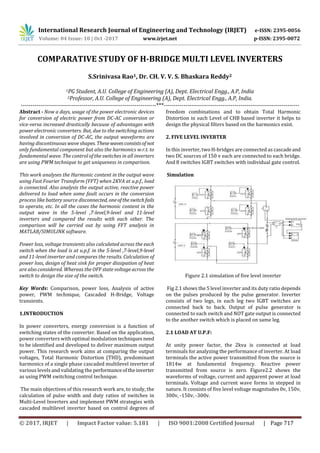
  • 1. International Research Journal of Engineering and Technology (IRJET) e-ISSN: 2395-0056 Volume: 04 Issue: 10 | Oct -2017 www.irjet.net p-ISSN: 2395-0072 © 2017, IRJET | Impact Factor value: 5.181 | ISO 9001:2008 Certified Journal | Page 717 COMPARATIVE STUDY OF H-BRIDGE MULTI LEVEL INVERTERS S.Srinivasa Rao1, Dr. CH. V. V. S. Bhaskara Reddy2 1PG Student, A.U. College of Engineering (A), Dept. Electrical Engg., A.P, India 2Professor, A.U. College of Engineering (A), Dept. Electrical Engg., A.P, India. ---------------------------------------------------------------------***--------------------------------------------------------------------- Abstract - Now a days, usage of the power electronic devices for conversion of electric power from DC-AC conversion or vice-versa increased drastically because of advantages with power electronic converters. But, due to the switching actions involved in conversion of DC-AC, the output waveforms are having discontinuous wave shapes. Thesewavesconsistsofnot only fundamental component but also the harmonics w.r.t. to fundamental wave. The control of the switches in all inverters are using PWM technique to get uniqueness in comparison. This work analyses the Harmonic content in the output wave using Fast Fourier Transform (FFT) when 2KVA at u.p.f., load is connected. Also analysis the output active, reactive power delivered to load when some fault occurs in the conversion process like battery source disconnected, oneoftheswitchfails to operate, etc. In all the cases the harmonic content in the output wave in the 5-level ,7-level,9-level and 11-level inverters and compared the results with each other. The comparison will be carried out by using FFT analysis in MATLAB/SIMULINK software. Power loss, voltage transients also calculated across the each switch when the load is at u.p.f. in the 5-level ,7-level,9-level and 11-level inverter and compares the results. Calculation of power loss, design of heat sink for proper dissipation of heat are also considered. Whereas the OFF state voltage across the switch to design the size of the switch. Key Words: Comparison, power loss, Analysis of active power, PWM technique, Cascaded H-Bridge, Voltage transients. 1.INTRODUCTION In power converters, energy conversion is a function of switching states of the converter. Based on the application, power converters with optimal modulationtechniquesneed to be identified and developed to deliver maximum output power. This research work aims at comparing the output voltages, Total Harmonic Distortion (THD), predominant harmonics of a single phase cascaded multilevel inverter of various levels and validating the performanceoftheinverter as using PWM switching control technique. The main objectives of this research work are, to study, the calculation of pulse width and duty ratios of switches in Multi-Level Inverters and implement PWM strategies with cascaded multilevel inverter based on control degrees of freedom combinations and to obtain Total Harmonic Distortion in each Level of CHB based inverter it helps to design the physical filters based on the harmonics exist. 2. FIVE LEVEL INVERTER In this inverter, two H-bridges are connected as cascadeand two DC sources of 150 v each are connected to each bridge. And 8 switches IGBT switches with individual gate control. Simulation Figure 2.1 simulation of five level inverter Fig 2.1 shows the 5 level inverter and its duty ratio depends on the pulses produced by the pulse generator. Inverter consists of two legs, in each leg two IGBT switches are connected back to back. Output of pulse generator is connected to each switch and NOT gate output is connected to the another switch which is placed on same leg. 2.1 LOAD AT U.P.F: At unity power factor, the 2kva is connected at load terminals for analyzing the performance of inverter. At load terminals the active power transmitted from the source is 1814w at fundamental frequency. Reactive power transmitted from source is zero. Figure2.2 shows the waveforms of voltage, current and apparent power at load terminals. Voltage and current wave forms in stepped in nature. It consists of five level voltage magnitudes 0v, 150v, 300v, -150v, -300v.
  • 2. International Research Journal of Engineering and Technology (IRJET) e-ISSN: 2395-0056 Volume: 04 Issue: 10 | Oct -2017 www.irjet.net p-ISSN: 2395-0072 © 2017, IRJET | Impact Factor value: 5.181 | ISO 9001:2008 Certified Journal | Page 718 Figure 2.2 output waveforms of Five level inverter at u.p.f. FFT analysis RMS value of Output voltage is 193.8 v i.e. it consists of DC , fundamental and harmonics of voltages. The RMS value of output voltage at fundamental frequency is 184.7v. And the waveform consists of 31.52%(THD) at fundamental frequency. The predominant harmonics are3rd-24.48%, 5th- 5.60% 7th-3.57% and th-8.00%. Fundamental RMS current 9.835A. 2.1.1 Power loss across switches Average power loss can be calculated by multiplying the voltage across and current through the switch . The figure 2.3 shows the waveforms of powerloss,voltageandcurrents in a switch. Each switch causes the power loss of 0.225W And in Five level inverter 8 no's of switches are used .So total average power loss in the bridge circuit is 1.8w. we conclude that the average power loss is same for all the power factors. Figure 2.3 power loss across switch Off state voltage Voltage across the switch when it is in OFF 150v i.e. the switch capable to withstand this voltage during turn off state. The forward break over voltage should be more than this voltage to avoid automatic turn on. Figure 2.3 showsthe voltage transients across the switch. 2.1.2 One battery source disconnected Figure 2.4 shows the apparent (active, reactive) powers delivered to load, when the battery is disconnectedfromone of its bridge. In both cases the power can be transmitted from another Even though the battery removed or suddenly disconnected from the bridge there is continuity ofpower to the load with reduction in power. In this case active power drawn by the load is 725 w and reactive power is zero. Figure 2.4 waveforms when one battery source disconnected FFT analysis RMS value of Output voltage is 122.3 v i.e. it consists of DC , fundamental and harmonics of voltages. The RMS value of output voltage at fundamental frequency(50 HZ) is 116.7 v. And the waveform consists of 30.54%(THD) at fundamental frequency. The predominant harmonics are 5th-20.10%,7th- 14.19% and 11th-9.00%. Fundamental RMS current 6.221 A. 2.1.3 Switch failed to turn on If the pulse generator failed to generate the gate pulse to IGBT or IGBT failed to turn on, in both the cases IGBT will not turn on. In this circumstancesanalyzeparametersatload terminals like output voltage, currents and harmonics. The active power delivered to load is 848 w. Figure 2.5 the output voltage, current, apparent poweratoutputterminals. Figure 2.5 Output waveforms when switch failed to turn on FFT analysis The RMS value of Output voltage is 150.2 v i.e. it consists of DC , fundamental and harmonics of voltages. The RMS value of output voltage at fundamental frequency (50 HZ) is 126.3
  • 3. International Research Journal of Engineering and Technology (IRJET) e-ISSN: 2395-0056 Volume: 04 Issue: 10 | Oct -2017 www.irjet.net p-ISSN: 2395-0072 © 2017, IRJET | Impact Factor value: 5.181 | ISO 9001:2008 Certified Journal | Page 719 v. And the waveform consists of 50.44%(THD) at fundamental frequency.The predominantharmonicsareDC- 28.1%, 2nd-23.1%,3rd-35.71%, 4th-11.52% and 5th- 1.11%. 3 SEVEN LEVEL INVERTER In this inverter, three H-bridges are connected as cascade and three equal DC sources of 100 v each(namely dc1, dc2, dc3) are connected to each bridge, and 12 switches IGBT switches with individual gate control. Simulation Figure3.1 Simulation of seven level inverter Fig 3.1 shows the seven level inverter and its duty ratio depends on the pulses produced by the pulse generator. Inverter consists of two legs , in each leg two IGBT switches are connected back to back. With same configuration seven level inverter consists of3bridges.Outputofpulsegenerator is connected to each switch and NOT gate output is connected to the another switch whichisplacedonsameleg. 3.1 LOAD:2KVA@UPF At unity power factor, the 2kva is connected at load terminals for analyzing the performance of inverter. At load terminals the active power transmitted from the source is 1879w at fundamental frequency. Reactive power transmitted from source is zero. Voltage and current wave forms in stepped in nature. It consists of 7 voltage magnitudes 0v, 100v, 200v, 300v, -100v,-150v,-300v.Figure 3.3 shows the voltage levels of inverter. Figure 3.2 output waveforms of Seven level inverter at u.p.f. FFT analysis RMS value of Output voltage is 187 v i.e. it consists of DC , fundamental and harmonics of voltages. The RMS value of output voltage at fundamental frequency is 181.3v. And the waveform consists of 25.47 %(THD) at fundamental frequency. The predominant harmonics are 3rd-20.67%, 5th- 1.65% 7th-4.25% and 9th- 3.31%.Fundamental RMS current 10.37 A. 3.1.1 Power loss across switches Average power loss can be calculated by multiplying the voltage across and current throughtheswitch.Thefigure3.3 the waveforms of power loss, voltage and currents in a switch. Each switch causes the power loss of 0.1w and in Seven level inverter 12 no's of switches are used .So total average power loss in the bridge circuit is 1.2w.Weconclude that the average power loss is same for all the powerfactors. Figure 3.3 power loss across switch Off state voltage Voltage across the switch when it is in OFF 100v i.e. the switch capable to withstand this voltage during turn off state. The forward break over voltage should be more than this voltage to avoid automatic turn on. Figure 3.3 showsthe voltage transients across the switch. 3.1.2 One battery source disconnected Figure 3.4 shows the apparent (active, reactive) powers delivered to load, when the battery is disconnectedfromone of its bridge. In both cases the power can be transmitted from another Even though the battery removed or suddenly disconnected from the bridge there is continuity ofpower to the load with reduction in power. In this case active power drawn by the load is 550w. and reactive power is zero. FFT analysis RMS value of Output voltage is 115.2v i.e. it consists of DC , fundamental and harmonics of voltages. The RMS value of output voltage at fundamental frequency(50 HZ) is 98.2v. And the waveform consists of 54.38%(THD) at fundamental
  • 4. International Research Journal of Engineering and Technology (IRJET) e-ISSN: 2395-0056 Volume: 04 Issue: 10 | Oct -2017 www.irjet.net p-ISSN: 2395-0072 © 2017, IRJET | Impact Factor value: 5.181 | ISO 9001:2008 Certified Journal | Page 720 frequency. The predominant harmonics are 3rd-49.80%,5th- 3.91%,7th-4.23%and9th-3.32%.Fundamental RMS current 6.221 A. Figure 3.4 waveforms when one battery source disconnected 3.1.3 Switch failed to turn on If the pulse generator failed to generate the gate pulse to IGBT or IGBT failed to turn on, in both the cases IGBT will not turn on. In this circumstancesanalyzeparametersatload terminals like output voltage, currents and harmonics. The active power delivered to load is 1116w. Figure 3.5 the output voltage, current,apparentpoweratoutputterminals. Figure3.5 Waveforms of seven level inverter (one switch fail) FFT analysis The RMS value of Output voltage is 154 v i.e.itconsistsof DC, fundamental and harmonics of voltages. The RMS value of output voltage at fundamental frequency(50 HZ) is 139v. And the waveform consists of 37.82%(THD) at fundamental frequency. The predominant harmonics areDC-18.98%,2nd- 11.36%, 3rd-30.84% and4th-8.05%. 4. NINE LEVEL INVERTER In this inverter, three H-bridges are connected as cascade and three equal DC sources of 75 v each are connected to each bridge, and 16 switches IGBT switches with individual gate control. Simulation Figure 4.1 Simulation of nine level inverter Figure 4.1 shows the nine level inverter and its duty ratio depends on the pulses produced by the pulse generator. Inverter consists of two legs , in each leg two IGBT switches are connected back to back. With same configuration nine level inverter consists of4bridges.Outputofpulsegenerator is connected to each switch and NOT gate output is connected to the another switch whichisplacedonsameleg. Figure 4.2 output waveforms of Nine level inverter at u.p.f. 4.1 LOAD:2KVA@UPF At unity power factor, the 2kva is connected at load terminals for analyzing the performance of inverter. At load terminals the active power transmitted from the source is 1908w at fundamental frequency. Reactive power
  • 5. International Research Journal of Engineering and Technology (IRJET) e-ISSN: 2395-0056 Volume: 04 Issue: 10 | Oct -2017 www.irjet.net p-ISSN: 2395-0072 © 2017, IRJET | Impact Factor value: 5.181 | ISO 9001:2008 Certified Journal | Page 721 transmitted from source is zero. Voltage and current wave forms in stepped in nature. It consists of 9 voltage magnitudes 0v, 75v, 150v, 225v, 300v, -75v, -150v, - 225v, - 300v.Figure 4.2 shows the voltage levels of inverter. FFT analysis RMS value of Output voltage is 183.6 v i.e. it consists of DC , fundamental and harmonics of voltages. The RMS value of output voltage at fundamental frequency is 179.3 v. And the waveform consists of 21.84 %(THD) at fundamental frequency. The predominant harmonics are 3rd-18.50%, 7th-4.40% and 9th- 1.76%. Fundamental RMS current10.65 A. 4.1.1 Power loss across switches Average power loss can be calculated by multiplying the voltage across and current through the switch . The figure shows the waveforms of power loss, voltage and currents in a switch. Each switch causes the power loss of0.056wand in nine inverter 16 no's of switches are used .So total average power loss in the bridge circuit is 0.7w.We conclude that the average power loss is same for all the power factors. Off state voltage Voltage across the switch when it is in OFF 75v i.e. the switch capable to withstand this voltage during turn off state. The forward break over voltage should be more than this voltage to avoid automatic turn on. Figure 4.3 showsthe voltage transients across the switch. 4.1.2 One battery source disconnected Figure 4.4 shows the apparent (active, reactive) powers delivered to load, when the battery is disconnected to one of its bridge. In both cases the power can be transmitted from another Even though the battery removed or suddenly disconnected from the bridge there is continuity ofpower to the load with reduction in power. In this case active power drawn by the load is 786.5w. and reactive power is zero. Figure 4.3 switching transients across the switch Figure4.4 waveforms of nine level inverter (one battery disconnected) FFT analysis RMS value of Output voltage is 125.4v i.e. it consists of DC , fundamental and harmonics of voltages. The RMS value of output voltage at fundamental frequency(50 HZ) is 115.2v. And the waveform consists of 43.05%(THD) at fundamental frequency. The Predominant Harmonicsare3rd-40.35%, 7th- 1.43 % and 9th- 3.43 %.Fundamental RMS current 6.8 A. 4.1.3 Switch failed to turn on Figure 4.5 waveforms of nine level inverter (one switch fail) If the pulse generator failed to generate the gate pulse to IGBT or IGBT failed to turn on, in both the cases IGBT will not turn on. In this circumstancesanalyzeparametersatload terminals like output voltage, currents and harmonics. The active power delivered to load is 1286w. Figure 4.5 shows the output voltage, current, apparent power at output terminals. FFT analysis The RMS value of Output voltage is 154 v i.e.itconsistsof DC, fundamental and harmonics of voltages. The RMS value of output voltage at fundamental frequency(50 HZ) is 139v. And the waveform consists of 28.97%(THD) at fundamental frequency. The predominant harmonics are DC-11.78 %,2nd 11.36%, 3rd-30.84% and4th-8.05%.
  • 6. International Research Journal of Engineering and Technology (IRJET) e-ISSN: 2395-0056 Volume: 04 Issue: 10 | Oct -2017 www.irjet.net p-ISSN: 2395-0072 © 2017, IRJET | Impact Factor value: 5.181 | ISO 9001:2008 Certified Journal | Page 722 5. ELEVEN LEVEL INVERTER In this inverter, three H-bridges are connected as cascade and three equal DC sources of 60 v each are connected to each bridge, and 16 switches IGBT switches with individual gate control. Simulation Figure 5.1 Simulation of nine level inverter Figure 5.1 shows the eleven level inverter and its duty ratio depends on the pulses produced by the pulse generator. Inverter consists of two legs , in each leg two IGBT switches are connected back to back. With same configuration eleven level inverter consists of4bridges.Outputofpulsegenerator is connected to each switch and NOT gate output is connected to the another switch whichisplacedonsameleg. 5.1 LOAD:2KVA@UPF Figure 5.2 Output waveforms of eleven level inverter at u.p.f. At unity power factor, the 2kva is connected at load terminals for analyzing the performance of inverter. At load terminals the active power transmitted from the source is 1921w at fundamental frequency. Reactive power transmitted from source is zero. Voltage and current wave forms in stepped in nature. It consists of 11 voltage magnitudes 0v, 60v, 120v, 180v, 240v, 300v, -60v, -120v, 180v, -240v, -300v.Figure 5.2 shows the voltage levels of inverter. FFT analysis RMS value of Output voltage is 181.5 v i.e. it consists of DC , fundamental and harmonics of voltages. The RMS value of output voltage at fundamental frequency is 178.1 v. And the waveform consists of 19.59%(THD) at fundamental frequency. The predominant harmonics are 3rd- 17.15 % and7th-3.64 % .Fundamental RMS current 10.8 A. 5.1.1 Power loss across switches Average power loss can be calculated by multiplying the voltage across and current through the switch . The figure 5.3 shows the waveforms of powerloss,voltageandcurrents in a switch. Each switch causes the power lossof0.036wand in eleven inverter 20 no's of switches are used .So total average power loss in the bridge circuit is 0.648w.We conclude that the average power loss is same for all the power factors. Off state voltage Voltage across the switch when it is in OFF60vi.e.theswitch capable to withstand this voltage during turn off state. The forward break over voltage should be morethanthisvoltage to avoid automatic turn on. Figure 5.3 shows the voltage transients across the switch. Figure 5.3 Voltage transients across switch 5.1.2 One battery source disconnected Figure 5.4 Waveforms of eleven level inverter (one battery disconnected)
  • 7. International Research Journal of Engineering and Technology (IRJET) e-ISSN: 2395-0056 Volume: 04 Issue: 10 | Oct -2017 www.irjet.net p-ISSN: 2395-0072 © 2017, IRJET | Impact Factor value: 5.181 | ISO 9001:2008 Certified Journal | Page 723 Figure 5.4 shows the apparent (active, reactive) powers delivered to load, when the battery is disconnectedfromone of its bridge. In both cases the power can be transmitted from another Even though the battery removed or suddenly disconnected from the bridge there is continuity ofpower to the load with reduction in power. In this case active power drawn by the load is 960w. and reactive power is zero. FFT analysis RMS value of Output voltage is 134v i.e. it consists of DC , fundamental and harmonics of voltages. The RMS value of output voltage at fundamental frequency(50 HZ) is 125.9v. And the waveform consists of 36.42%(THD) at fundamental frequency. The Predominant Harmonics are 3rd-34.48 %, 5th 1.15% and 7th- 3.73 %.Fundamental RMS current 7.635 A. 5.1.3 Switch failed to turn on Figure 5.5 waveforms of eleven level inverter (one switch fail) If the pulse generator failed to generate the gate pulse to IGBT or IGBT failed to turn on, in both the cases IGBT will not turn on. In this circumstancesanalyzeparametersatload terminals like output voltage, currents and harmonics. The active power delivered to load is 1399w. Figure 5..5 the output voltage, current,apparentpoweratoutputterminals. FFT analysis The RMS value of Output voltage is 159.5 v i.e. it consists of DC , fundamental and harmonics of voltages. The RMS value of output voltage at fundamental frequency(50 HZ) is 152v. And the waveform consists of 27.22%(THD) at fundamental frequency. The predominant harmonics are DC-11.50 %, 2nd-4.38%, 3rd-24.32%, 4th -8.05% and 6th-2.95%.Figure 3.56 shows the % magnitude of harmonics w.r.t. to fundamental frequency. 6. CONCLUSIONS 6.1 FOLLOWING ARE THE CONCLUSIONS DRAWN FROM THE PRESENT STUDY As the level increases the Apparent (Active, Reactive ) power transmitted at load increases at fundamental frequency, i.e., at 5 -level, 11- level active power loads are 1814w, 1921w respectively at unity power factor. Total Harmonic Distortion (THD) are 5-level, 7-level , 9- level , 11- level are 31.52%, 25.47%, 21.84% and 19.58% respectively. Concluded that THD decreases and power transmission increases with level of conversion at unity power factor. Magnitude of 3rd harmonic (predominant one) content in five level- 24.48%, seven level-20.67%, nine level-18.50% and eleven level- 17.15%.Predominantharmonicmagnitude decreases as the level increases. As the level increases the lower order harmonic content decreases , it is consideration of design the filter. Size of filter is low for 11 level converter. Power loss in the switch for five level is 0.225w and total power loss is 1.8w, seven level power loss is 0.1w and total loss 1.2w , nine level power loss 0.056w and total loss0.7w and for eleven level power loss in each switch is 0.036w and total loss 0.648w. concluded that power loss also decreases in 11 level compared to five level inverter. Power loss is same in all inverters for any power factors. Proper heat dissipation methods need to be consider for five level because the power loss is high. Voltage across each switch during off state for five level:150v, seven level:100v, ninelevel:75v,elevenlevel:60v. From above concluded that , the voltage across eleven level inverter is low. The size of the switch used in this inverter is low. 6.2 SCOPE FOR FURTHER STUDY The present work can be extended by increasing number of levels, so that Total Harmonic Distortion (THD), magnitude of harmonics decreasesand apparentpower(active,reactive power) transmission increases at fundamental frequency. REFERENCES [1]. J.S. Lai and F. Z. Peng, “Multilevel Converters - A new breed of Power converters", IEEE Transactions on Industry Application, Volume 32, May June 1996. [2]. Power quality improvement in transmission systems using facts devices Published in: Green Engineering and Technologies (IC-GET), 2016 Online International Conference on Coimbatore, India 19-19 Nov. 2016. [3]. L. M. A. Beigi, L. M. A. Beigi, F. Khosravi "A new multilevel inverter topology with reduced number of power switches" Published in: Power and Energy
  • 8. International Research Journal of Engineering and Technology (IRJET) e-ISSN: 2395-0056 Volume: 04 Issue: 10 | Oct -2017 www.irjet.net p-ISSN: 2395-0072 © 2017, IRJET | Impact Factor value: 5.181 | ISO 9001:2008 Certified Journal | Page 724 (PECon),2012 IEEE International Conference on 2- 5Dec.2012. [4]. llhami Colak, Ersan Kabalci, Ramazan Bayindir"Review of multi-level source inverter topologies and control schemes"published in Energy Conversion and Management in 2011. [5]. M. Bashi, N. Mariun, N.F. Mailah and S. Alhalali, 2008. Low Harmonics Single Phase Multilevel Power Inverter. Asian Journal of Scientific Research, 1: 274- 280. [6]. Lakhan Kumar Gupta, K. T. Chaturvedi, Bhoopendra Singh, Toshi Sharma,Jayadeep Srikakolapu," Simulation of a Cascade Connected H–Bridge Five level Inverter",2014IEEE International conference onMOOC, Innovation and technology in Education (MITE)