SlideShare a Scribd company logo
1 of 5
Download to read offline
Eze et al. Int. Journal of Engineering Research and Applications www.ijera.com
ISSN: 2248-9622, Vol. 5, Issue 7, (Part - 1) July 2015, pp.01-05
www.ijera.com 1 | P a g e
The Level of Base Oil Recovery from Niger Delta Drill Cuttings
Using Thermal Desorption Unit
Eze,1
C. L., Iheonu,2
C. A and Godwin, 3
A. C.
1,2
Institute of Geosciences and Space Technology, Rivers State University of Science and Technology, Port
Harcourt, Nigeria. Petroleum Engineering Department, Rivers State University of Science and Technology, Port
Harcourt, Nigeria.
ABSTRACT
In bid to determine the level of base oil recovery using thermal desorption unit, a process that provides for waste
reduction and recycling, ten samples of oil based mud contaminated drill cuttings were collected from ten oil
wells in the Niger Delta are in Nigeria. Composite samples were formed from each oil well sample and a retort
analysis was made of each composite sample, to determine the percentage of oil and water in the oily cuttings
and the temperature for the thermal desorption treatment of these oily cuttings. The results of the retort analysis
showed an average percentage range of oil and water content as 6.93 – 23.93% and 4.00 – 15.00% respectively
and presented a suitable temperature range of 325°C – 350°C for the thermal desorption treatment. All the drill
cuttings were then treated in a Thermal Desorption Unit (TDU). Another retort analysis was carried out on the
processed solids (cleaned cuttings) to determine the level of oil residue, which stood at 0.19 – 0.79%. This is
below the regulatory limit of 1%. This study reveals the efficiency of TDU process in the recovery of oil from
drill cuttings from the Niger Delta area of Nigeria.
Key word: Drill cutting, Base oil, Thermal desorption, Cleaning cutting
I. INTRODUCTION
1.1 Generation of Drill Cuttings
All the activities involved in the hydrocarbon
exploration and production normally have one
impact or the other on the environment (Odiete,
1999). Drill cuttings represent one of the most
significant waste streams in the upstream oil and gas
industry and they require effective and efficient
treatment and disposal (Onwukwe, 2014). Oily drill
cuttings cannot be discharged directly into a
disposal site, not only because of their adverse effect
upon the environment, but additionally because the
great value of the oil contained in them. The
creation of a single vertical well bore to an average
depth of 1000m brings up about 45m3
of cuttings,
including radioactive substances and heavy metals
from below, mixed with the chemicals in the drilling
fluid (Ormeloh, 2014). Horizontal wells will
produce much more of this material as do vertical
wells (Ferrari et al., 2000).
1.2 Disposal of Drill Cuttings
Drill cutting is basically a waste product from
drilling process and consists of particles from the
formation mixed with remains of drilling fluids,
chemicals and in some cases oil from the formation.
The drill cuttings produced by an oil based drilling
fluid are rather heavily contaminated by the oil base
which is used for preparing the drilling fluid. When
such drill cuttings are disposed of without recovery
of the oil, the disposal often results in the
contamination of the environment. It is therefore
necessary to take steps to recover this oil in order to
reduce the contamination and also save some cost.
Drilling fluids, cuttings and well bore clean-up
fluids require some form of treatment prior to
disposal or recycling as regulatory bodies and oil
companies apply higher environmental standards.
Moreover, companies spend a huge amount of
money buying fresh oil to be used as drilling base.
The oily drill cannot be discharged directly into a
disposal site, not only because their adverse effect
upon the environment, but additionally because of
the great value of the oil contained in them. The first
step in managing drilling wastes is to separate the
solid cuttings from the liquid drilling mud. Once
solid and liquid drilling wastes have been separated,
companies can use a variety of technologies and
practice to treat the wastes before disposal
(Onwukwe, 2014). Various approaches have been
attempted to remove the oil from the rock such as
the use of a high temperature, liquid solvent
extraction and soap and water washing (Perry and
Griffin, 2001). Drill cuttings injection started in the
late 1980’s and has now become an industry-
accepted solution performed in a wide range of
wells and locations (Saasen et al., 2000). However,
if re-injection of the waste is not technically or
economically feasible, the waste must be treated to
RESEARCH ARTICLE OPEN ACCESS
Eze et al. Int. Journal of Engineering Research and Applications www.ijera.com
ISSN: 2248-9622, Vol. 5, Issue 7, (Part - 1) July 2015, pp.01-05
www.ijera.com 2 | P a g e
reduce oil concentration prior to final disposal.
There is also the risk of groundwater contamination
during reinjection (Meinhold, 1999).
1.3 Objective of the Study
This study therefore was set to determine the level
of base oil recovery using thermal desorption unit
before disposing oily cuttings with particular
reference to the Niger Delta area of Nigeria. It is
also aimed at assessing the efficiency of low
temperature thermal desorption in oil and water
recovery from drill cuttings from the same region.
II. METHODOLOGY
2.1 Sample Collection
The oil based mud contaminated drill cuttings
samples were collected from ten wells across the
Niger Delta area of Nigeria. The oil contaminated
drill cuttings were transported to the facility in
specially designed, water-tight, leak-proof skips.
2.2 Retort Analysis Prior to Treatment
A retort analysis was carried on the samples to
determine the level of base oil contamination of the
cuttings. Samples from the same well were bulked
together to form a composite sample. A retort
analysis was made of each composite sample to
determine the percentage of oil and water in the oily
cuttings at 345°C.
50 grams of the bulk sample was heated at 345°C
for one hour, to vaporize the liquid components
which were then condensed and collected in a
graduated cylinder. Liquid volumes were
determined from reading the oil and water phases on
the graduated cylinder. The total volume of solids,
both suspended and dissolved, was obtained by
noting the difference of the total sample volume
versus the final liquid volume collected. The
percentage of oil and water in the oily cuttings were
thus noted (Table 1).
2.3 Thermal Processing
The samples were treated in a Thermal Desorption
Unit (TDU). Thermal Desorption process is suited
to processing a wide range of oil contaminated
waste cuttings and extracting, through a distillation
process, and recovering any hydrocarbon content,
which will evaporate at temperature below 325o
C.
Hydrocarbons are volatized from oily solids in a
closed chamber using controlled heat. The dry
boiling point of base oil is 327° C (Ormeloh, 2014).
However, operating the unit at a lower temperature
so close to the actual boiling point of the oil would
increase the required cuttings residency time in the
TDU and therefore could negatively impact
treatment rates. From a process perspective, the best
scenario is to operate at highest possible temperature
without cracking the oil. The process achieves
maximum phase separation without exceeding the
fractionation point of the base oil. Thermal cracking
temperature is a function of molecule size. Larger
molecules crack at lower temperatures.
Hydrocarbons that are used as the base oil for
drilling fluids contain relatively short-chain, small
molecules that do not crack at the temperatures
normally reached in thermal desorption units.
All thermal desorption processes evaporate the oil
and water from the cuttings. The heat required to
evaporate the oil and water provides enough energy
to remove and separate emulsified oil as well. Free
and emulsified oil and water are removed by
distillation, and in the process, water evaporates first
to produce steam. Oil has a higher boiling point and
evaporates after the water. The production of steam
can also assist in lowering the boiling point of oil.
The process began by the empting of the skips into
the storage coral where the drill cuttings are stored
before they are processed in order to return the skips
and to allow for regular operation of the plant
(Figure 1). The drill cuttings enters the system
through a special non-plugging design feed hopper
with the use of a loader. The feed hopper is
equipped with a weighing device and variable speed
auger-feeder that meters the material into the rotary
dryer. The system can process a wide range of
particle sizes from clay to rock.
The exclusive, stainless steel dryer unit is designed
to dry and heat the drill cuttings indirectly through
conductive heat transfer. This prevents combustion
gases from contacting the cuttings or the
hydrocarbon/water gas stream. The externally-
heated rotary dryer is sealed on either end to limit
oxygen entering the system or vapor exiting the
system.
A special cleaning system in the dryer eliminates
caking of solids and keeps the material agitated to
allow for even heating. The cuttings temperature is
increased to vapourize the water and hydrocarbons
in the cuttings. The temperature in this particular
process is 345o
C.
Eze et al. Int. Journal of Engineering Research and Applications www.ijera.com
ISSN: 2248-9622, Vol. 5, Issue 7, (Part - 1) July 2015, pp.01-05
www.ijera.com 3 | P a g e
Figure 1: Thermal Desorption Unit Flow Diagram
The hydrocarbon and water vapours pass through a
quench-scrubber for particulate removal. At the
adiabatic quench, where water is sprayed on the
vapour phase, converting it to liquid phase. The pre
quench works on the same principle as the quench,
but is designed to knock off fine dust particles
earlier and pumped to the centrifuge. This stage
removes any residual ultra-fine dust particles from
the gas-air stream and ensures recovery of a clean,
usable oil or synthetic fluid. The scrubbed oil and
water gas-stream mix enters one or more condensers
to return the oil and water to a liquid state. This unit
is for condensing all gasses that were not condensed
at the quench process. The cooling tower is a heat
exchanger, which cools the water from the quench
process.
The thermal oxidizer unit oxidizes the mixture and
destroys any non-condensable hydrocarbons and
ensures clean emissions. The mixture is processed
through an oil/water separator and coalesces to
separate the mixture into clean water and oil, or
synthetic fluid. The centrifuge is used to remove
ultra-fine solids from the process while the weir
tank as the name implies is made of weir plates,
used for typical separation of oil and water. Oil goes
on top of the weir, while water goes under. The
solids are bubbled using air to the centrifuge sump
where they are pumped to the centrifuge.
Processed drill cuttings leaving the dryer and dust
leaving the bag-house is mixed with the recovered
water in the pugmill soil conditioner. The added
water cools the processed cuttings and controls dust
before releasing the ash into the ash pit. Processed
cuttings are collected at this point and tested. The
processed, conditioned cuttings can then be back-
filled or transported offsite for ultimate disposal or
recycling. For each 100 tons of drill cuttings treated,
Ntukidemet al., (2002) estimate process recovers on
the average between 10 - 15 cubic meters of oil. The
recovered oil is very high quality and is suitable for
in the fabrication of new drilling mud. The TDU
process reduces the waste volume by approximately
20%. The recovered oil is moved to a storage tank
and can be used as fuel for the primary burners,
recycled into fresh drilling mud, or returned to the
client.Testing of recovered base oil has shown no
significant degradation or formation of new
hydrocarbon chains during the thermal process
(Zupan and Kapila, 2000). The water derived from
the process is stored in tanks to be reused with fresh
water in the process again.
2.4 Retort Analysis after Treatment
Retort was repeated on the clean cutting from the
TDU outlet. 50 grams of the bulk sample was heated
at 350°C for one hour, to vaporize the liquid
components which was then condensed and
collected in a graduated cylinder. The percentage oil
and water content was noted against the initial
content.
Eze et al. Int. Journal of Engineering Research and Applications www.ijera.com
ISSN: 2248-9622, Vol. 5, Issue 7, (Part - 1) July 2015, pp.01-05
www.ijera.com 4 | P a g e
III. RESULTS AND DISCUSSIONS
The thermal desorption treatment of the drill
cuttings from the ten wells is presented in Table 1
below. A comparison of the retort analysis before
and after the thermal desorption treatment shows
that the oil from the drill cuttings was reduced to the
barest minimum level ranging from 0.19% - 0.79%
which comply with the stipulated DPR regulation of
1% oil residue in clean cuttings. For every 6.8tons
of drill cuttings 1m3
of base oil is recovered. This is
equivalent to base oil recovery rate of 14.70m3
for
every 100tons of contaminated drill cutting. This
rate is considered very good when compared to the
10-15m3
estimated by Ntukidemet al., (2002)
Table 1: Summary of Drill Cuttings Treatment (TDU operations results) of the Ten Oil Wells
Well
Names
Treated
cuttings
(tons)
Recovered
oil in m3
Recovered
water in m3
Recovered
cleaned
cuttings
(tons)
Oil % in
cuttings
before
Treatment
Oil % in
cuttings after
Treatment
Well A 46.80 5.30 4.80 36.78 23.93 0.52
Well B 66.42 13.02 10.96 42.50 10.60 0.79
Well C 55.54 11.00 11.60 33.20 11.47 0.75
Well D 45.89 5.10 4.30 36.50 6.93 0.30
Well E 46.51 6.01 5.25 35.28 8.67 0.20
Well F 46.34 6.20 4.55 35.64 7.33 0.19
Well G 54.64 8.45 7.34 38.88 9.87 0.43
Well H 43.08 6.05 5.95 31.15 10.67 0.25
Well I 49.26 6.10 6.70 36.50 12.07 0.64
Well J 45.28 6.25 6.00 33.10 13.07 0.53
Total 499.76 73.48 67.50 359.53 114.61 4.60
IV. CONCLUSIONS AND
RECOMMENDATIONS
Critical observation of the analytical results
have shown that the thermal desorption unit is one of
the best technology that can be used to recover oil
from drill cuttings. Apart from recovering almost
100% of oil from the drill cuttings, this process also
minimizes future environmental liability, reduces
land requirements and provides for waste reduction
and recycling. The recovered oil is suitable for reuse
in the fabrication of new drilling mud. The
recovered water in most cases are being reused in
moistening the dry processed clean solids to prevent
dusting effect during processing. The cleaned
cuttings can be reused for construction purposes and
backfilling of swampy areas. It is recommended that
drill cutting producing companies apply the use of
Thermal Desorption Units for the treatment of their
oil contaminated drill cuttings to help save cost,
reduce wastes, improve public image and also save
the environment from contamination.
REFERENCES
[1] Ferrari G., Ceccini F. and Xiao L. (2000);
Drilling Wastes Treatment and Management
Practices For Reducing Impact on HSE:
ENI/AGIP experiences.In the proceedings of
the SPE International Oil and Gas
Conference and Exhibition, China, Beijing,
pp. 1-11
[2] Meinhold, A.F. (1999). Framework for a
Comparative Environmental Assessment of
Drilling Fluids Used Offshore. In the
proceedings of the 1999 SPE/EPA
Exploration and Production Environmental
Conference, Austin, TX, pp. 20.
[3] Ntukidem, J., Anighoro, S., & Omonigho, R.
(2002). Thermal Desorption as an Alternative
to Cuttings Reinjection in Niger Delta Waste
Management Operations. In the proceedings
of the 2003 SPE International Conference on
Health, Safety and Environment in Oil and
Gas Exploration, Abuja, Nigeria. pp 2 – 6.
[4] Odiete W.O. (1999); Environmental
Physiology of Animals and Pollution.
Diversified resources Ltd. Lagos, Nigeria. pp:
261.
[5] Ormeloh Jan (2014);Thermomechanical
Cuttings Cleaner –Qualification for Offshore
Treatment of Oil Contaminated Cuttings on
the Norwegian Continental Shelf and Martin
Linge Case Study.
http://brage.bibsys.no/xmlui/
bitstream/handle/11250/220918/Ormeloh_Jan
.pdf (Accessed 26-02-2015).
[6] Onwukwe S. I. (2014); Adaptation of
Thermal Desorption in the Treatment of Oil
Based Drill Cuttings. International Journal of
Eze et al. Int. Journal of Engineering Research and Applications www.ijera.com
ISSN: 2248-9622, Vol. 5, Issue 7, (Part - 1) July 2015, pp.01-05
www.ijera.com 5 | P a g e
Engineering and Technical Research, 2(12),
pp. 78-80
[7] Perry, M. L., and Griffin, J. M. (2001).
Chemical Treatment of Cuttings Drilled with
Oil Based Mud Employing a Laboratory
Simulated Soil Washing Procedure. In the
proceedings of Exploration and Production
Environmental Conference, San Antonio,
Texas, pp. 13 – 21
[8] Saasen, A., Paulsen, J. E. and Hoithe, K.
(2000). Environmental Priorities of Re-
injection and Land Based Handling of Drilled
Cuttings and Affiliated Fluids. In the
proceedings of the SPE International
Conference on Health, Safety, and the
Environment in Oil and Gas Exploration and
Production, Stavanger, Norway, pp. 3 – 10
[9] Zupan, T., and Kapila, M. (2000). Thermal
Desorption of Drill Muds and Cuttings in
Ecuador: The Environmental and Financially
Sound Solution. In the proceedings of
International Conference on Health, Safety
and Environment in Oil and Gas Exploration
and Production, Ecuador, pp. 12-16.

More Related Content

What's hot

Eng. ch. rama krushna chary drilling waste management
Eng. ch. rama krushna chary  drilling waste managementEng. ch. rama krushna chary  drilling waste management
Eng. ch. rama krushna chary drilling waste managementpromediakw
 
integrated green Technologies for MSW
integrated green Technologies for MSWintegrated green Technologies for MSW
integrated green Technologies for MSWMamdouh Abdel-Sabour
 
Cleaning up Gasification Producer Gas for Use in an IC Engine
Cleaning up Gasification Producer Gas for Use in an IC EngineCleaning up Gasification Producer Gas for Use in an IC Engine
Cleaning up Gasification Producer Gas for Use in an IC Engineeisenmannusa
 
Oil and gas refinery
Oil and gas refineryOil and gas refinery
Oil and gas refineryDipo Elegbs
 
Research Published Paper-Feb 2016-Morocco-4845
Research Published Paper-Feb 2016-Morocco-4845Research Published Paper-Feb 2016-Morocco-4845
Research Published Paper-Feb 2016-Morocco-4845Ibrahim Abdel-Rahman
 
Hot producer gas cleaning system
Hot producer gas cleaning systemHot producer gas cleaning system
Hot producer gas cleaning systemNainesh Patel
 
GPO Application Dataset
GPO Application DatasetGPO Application Dataset
GPO Application Datasetjnic
 
Biodiesel from microalgae: A chemical process approach
Biodiesel from microalgae: A chemical process approachBiodiesel from microalgae: A chemical process approach
Biodiesel from microalgae: A chemical process approachAngel Darío González-Delgado
 

What's hot (9)

Eng. ch. rama krushna chary drilling waste management
Eng. ch. rama krushna chary  drilling waste managementEng. ch. rama krushna chary  drilling waste management
Eng. ch. rama krushna chary drilling waste management
 
integrated green Technologies for MSW
integrated green Technologies for MSWintegrated green Technologies for MSW
integrated green Technologies for MSW
 
Cleaning up Gasification Producer Gas for Use in an IC Engine
Cleaning up Gasification Producer Gas for Use in an IC EngineCleaning up Gasification Producer Gas for Use in an IC Engine
Cleaning up Gasification Producer Gas for Use in an IC Engine
 
Oil and gas refinery
Oil and gas refineryOil and gas refinery
Oil and gas refinery
 
Research Published Paper-Feb 2016-Morocco-4845
Research Published Paper-Feb 2016-Morocco-4845Research Published Paper-Feb 2016-Morocco-4845
Research Published Paper-Feb 2016-Morocco-4845
 
Hot producer gas cleaning system
Hot producer gas cleaning systemHot producer gas cleaning system
Hot producer gas cleaning system
 
GPO Application Dataset
GPO Application DatasetGPO Application Dataset
GPO Application Dataset
 
Biodiesel from microalgae: A chemical process approach
Biodiesel from microalgae: A chemical process approachBiodiesel from microalgae: A chemical process approach
Biodiesel from microalgae: A chemical process approach
 
Hwm ppt
Hwm pptHwm ppt
Hwm ppt
 

Viewers also liked

Serviceability behavior of Reinforcement Concrete beams with polypropylene an...
Serviceability behavior of Reinforcement Concrete beams with polypropylene an...Serviceability behavior of Reinforcement Concrete beams with polypropylene an...
Serviceability behavior of Reinforcement Concrete beams with polypropylene an...IJERA Editor
 
Analyzing Specialized Views of Transportation Under Mean Safety By Using Fuzz...
Analyzing Specialized Views of Transportation Under Mean Safety By Using Fuzz...Analyzing Specialized Views of Transportation Under Mean Safety By Using Fuzz...
Analyzing Specialized Views of Transportation Under Mean Safety By Using Fuzz...IJERA Editor
 
Modelo queja Defensor del Pueblo Andaluz
Modelo queja Defensor del Pueblo AndaluzModelo queja Defensor del Pueblo Andaluz
Modelo queja Defensor del Pueblo AndaluzCEMER
 

Viewers also liked (9)

Partidos en vivo
Partidos en vivoPartidos en vivo
Partidos en vivo
 
Serviceability behavior of Reinforcement Concrete beams with polypropylene an...
Serviceability behavior of Reinforcement Concrete beams with polypropylene an...Serviceability behavior of Reinforcement Concrete beams with polypropylene an...
Serviceability behavior of Reinforcement Concrete beams with polypropylene an...
 
Geo report 1
Geo report 1Geo report 1
Geo report 1
 
MIG 中国
MIG 中国MIG 中国
MIG 中国
 
Kekar
KekarKekar
Kekar
 
Happy New Year
Happy  New  YearHappy  New  Year
Happy New Year
 
Analyzing Specialized Views of Transportation Under Mean Safety By Using Fuzz...
Analyzing Specialized Views of Transportation Under Mean Safety By Using Fuzz...Analyzing Specialized Views of Transportation Under Mean Safety By Using Fuzz...
Analyzing Specialized Views of Transportation Under Mean Safety By Using Fuzz...
 
El término web 2.0
El término web 2.0El término web 2.0
El término web 2.0
 
Modelo queja Defensor del Pueblo Andaluz
Modelo queja Defensor del Pueblo AndaluzModelo queja Defensor del Pueblo Andaluz
Modelo queja Defensor del Pueblo Andaluz
 

Similar to The Level of Base Oil Recovery from Niger Delta Drill Cuttings Using Thermal Desorption Unit

Treatment of aged transformer oil using dry sludge in lab-scale refining unit
Treatment of aged transformer oil using dry sludge in lab-scale refining unitTreatment of aged transformer oil using dry sludge in lab-scale refining unit
Treatment of aged transformer oil using dry sludge in lab-scale refining unitPremier Publishers
 
Pyrolysis of Scrap Tyres and Waste Lube Oil by Using Catalytic Agent
Pyrolysis of Scrap Tyres and Waste Lube Oil by Using Catalytic AgentPyrolysis of Scrap Tyres and Waste Lube Oil by Using Catalytic Agent
Pyrolysis of Scrap Tyres and Waste Lube Oil by Using Catalytic AgentIJERA Editor
 
Oill shale booklet
Oill shale bookletOill shale booklet
Oill shale bookletMahmoud Aref
 
Oil Shale Ex-Situ Process - Leaching Study of Spent Shale
Oil Shale Ex-Situ Process - Leaching Study of Spent ShaleOil Shale Ex-Situ Process - Leaching Study of Spent Shale
Oil Shale Ex-Situ Process - Leaching Study of Spent Shaleinventionjournals
 
2 ijaems sept-2015-2-experimental investigation of waste transformer oil as a...
2 ijaems sept-2015-2-experimental investigation of waste transformer oil as a...2 ijaems sept-2015-2-experimental investigation of waste transformer oil as a...
2 ijaems sept-2015-2-experimental investigation of waste transformer oil as a...INFOGAIN PUBLICATION
 
“On-site Remediation of Sea Sediment and Soil Contaminated with Crude Oil at ...
“On-site Remediation of Sea Sediment and Soil Contaminated with Crude Oil at ...“On-site Remediation of Sea Sediment and Soil Contaminated with Crude Oil at ...
“On-site Remediation of Sea Sediment and Soil Contaminated with Crude Oil at ...Meherunnesha (Nishat)
 
2212208 distillation-of-herbs
2212208 distillation-of-herbs2212208 distillation-of-herbs
2212208 distillation-of-herbsHassan325
 
Optimizing Reactor Parameters to Achieve Higher Process Yield in Ex-Situ Oil ...
Optimizing Reactor Parameters to Achieve Higher Process Yield in Ex-Situ Oil ...Optimizing Reactor Parameters to Achieve Higher Process Yield in Ex-Situ Oil ...
Optimizing Reactor Parameters to Achieve Higher Process Yield in Ex-Situ Oil ...IJERA Editor
 
Application of Thermal Methods for Heavy Oil.pdf
Application of Thermal Methods for Heavy Oil.pdfApplication of Thermal Methods for Heavy Oil.pdf
Application of Thermal Methods for Heavy Oil.pdfLuisarmandoGarcianav
 
Production of diesel like fuel from waste engine oil and engine performance t...
Production of diesel like fuel from waste engine oil and engine performance t...Production of diesel like fuel from waste engine oil and engine performance t...
Production of diesel like fuel from waste engine oil and engine performance t...IRJEETJournal
 
Heavy Oil Recovery: Environmental Implications and Mitigation Measures
Heavy Oil Recovery: Environmental Implications and Mitigation Measures Heavy Oil Recovery: Environmental Implications and Mitigation Measures
Heavy Oil Recovery: Environmental Implications and Mitigation Measures Premier Publishers
 
Development of a Laboratory Scale Biodiesel Batch Reactor
Development of a Laboratory Scale Biodiesel Batch ReactorDevelopment of a Laboratory Scale Biodiesel Batch Reactor
Development of a Laboratory Scale Biodiesel Batch ReactorIRJET Journal
 
Plastic waste ppt
Plastic waste pptPlastic waste ppt
Plastic waste pptshubhanggg
 
Spatial Distribution of Residual Petroleum Hydrocarbons in an Oil Spill Site ...
Spatial Distribution of Residual Petroleum Hydrocarbons in an Oil Spill Site ...Spatial Distribution of Residual Petroleum Hydrocarbons in an Oil Spill Site ...
Spatial Distribution of Residual Petroleum Hydrocarbons in an Oil Spill Site ...Premier Publishers
 
IRJET- A Review on Study of Different Types of Evaporators and their Software
IRJET- A Review on Study of Different Types of Evaporators and their SoftwareIRJET- A Review on Study of Different Types of Evaporators and their Software
IRJET- A Review on Study of Different Types of Evaporators and their SoftwareIRJET Journal
 

Similar to The Level of Base Oil Recovery from Niger Delta Drill Cuttings Using Thermal Desorption Unit (20)

Treatment of aged transformer oil using dry sludge in lab-scale refining unit
Treatment of aged transformer oil using dry sludge in lab-scale refining unitTreatment of aged transformer oil using dry sludge in lab-scale refining unit
Treatment of aged transformer oil using dry sludge in lab-scale refining unit
 
Pyrolysis of Scrap Tyres and Waste Lube Oil by Using Catalytic Agent
Pyrolysis of Scrap Tyres and Waste Lube Oil by Using Catalytic AgentPyrolysis of Scrap Tyres and Waste Lube Oil by Using Catalytic Agent
Pyrolysis of Scrap Tyres and Waste Lube Oil by Using Catalytic Agent
 
Oill shale booklet
Oill shale bookletOill shale booklet
Oill shale booklet
 
Oil Shale Ex-Situ Process - Leaching Study of Spent Shale
Oil Shale Ex-Situ Process - Leaching Study of Spent ShaleOil Shale Ex-Situ Process - Leaching Study of Spent Shale
Oil Shale Ex-Situ Process - Leaching Study of Spent Shale
 
2 ijaems sept-2015-2-experimental investigation of waste transformer oil as a...
2 ijaems sept-2015-2-experimental investigation of waste transformer oil as a...2 ijaems sept-2015-2-experimental investigation of waste transformer oil as a...
2 ijaems sept-2015-2-experimental investigation of waste transformer oil as a...
 
“On-site Remediation of Sea Sediment and Soil Contaminated with Crude Oil at ...
“On-site Remediation of Sea Sediment and Soil Contaminated with Crude Oil at ...“On-site Remediation of Sea Sediment and Soil Contaminated with Crude Oil at ...
“On-site Remediation of Sea Sediment and Soil Contaminated with Crude Oil at ...
 
2212208 distillation-of-herbs
2212208 distillation-of-herbs2212208 distillation-of-herbs
2212208 distillation-of-herbs
 
8 ee7 hve lab manual
8 ee7 hve lab manual8 ee7 hve lab manual
8 ee7 hve lab manual
 
Optimizing Reactor Parameters to Achieve Higher Process Yield in Ex-Situ Oil ...
Optimizing Reactor Parameters to Achieve Higher Process Yield in Ex-Situ Oil ...Optimizing Reactor Parameters to Achieve Higher Process Yield in Ex-Situ Oil ...
Optimizing Reactor Parameters to Achieve Higher Process Yield in Ex-Situ Oil ...
 
Application of Thermal Methods for Heavy Oil.pdf
Application of Thermal Methods for Heavy Oil.pdfApplication of Thermal Methods for Heavy Oil.pdf
Application of Thermal Methods for Heavy Oil.pdf
 
Mining, Maintenance and the Environment
Mining, Maintenance and the EnvironmentMining, Maintenance and the Environment
Mining, Maintenance and the Environment
 
19CHR061 PPT-1 PHASE 2 (1).pptx
19CHR061 PPT-1 PHASE 2 (1).pptx19CHR061 PPT-1 PHASE 2 (1).pptx
19CHR061 PPT-1 PHASE 2 (1).pptx
 
Production of diesel like fuel from waste engine oil and engine performance t...
Production of diesel like fuel from waste engine oil and engine performance t...Production of diesel like fuel from waste engine oil and engine performance t...
Production of diesel like fuel from waste engine oil and engine performance t...
 
D05711618
D05711618D05711618
D05711618
 
Heavy Oil Recovery: Environmental Implications and Mitigation Measures
Heavy Oil Recovery: Environmental Implications and Mitigation Measures Heavy Oil Recovery: Environmental Implications and Mitigation Measures
Heavy Oil Recovery: Environmental Implications and Mitigation Measures
 
Development of a Laboratory Scale Biodiesel Batch Reactor
Development of a Laboratory Scale Biodiesel Batch ReactorDevelopment of a Laboratory Scale Biodiesel Batch Reactor
Development of a Laboratory Scale Biodiesel Batch Reactor
 
Plastic waste ppt
Plastic waste pptPlastic waste ppt
Plastic waste ppt
 
MEM’s for HO-EOR evaluation
MEM’s for HO-EOR evaluationMEM’s for HO-EOR evaluation
MEM’s for HO-EOR evaluation
 
Spatial Distribution of Residual Petroleum Hydrocarbons in an Oil Spill Site ...
Spatial Distribution of Residual Petroleum Hydrocarbons in an Oil Spill Site ...Spatial Distribution of Residual Petroleum Hydrocarbons in an Oil Spill Site ...
Spatial Distribution of Residual Petroleum Hydrocarbons in an Oil Spill Site ...
 
IRJET- A Review on Study of Different Types of Evaporators and their Software
IRJET- A Review on Study of Different Types of Evaporators and their SoftwareIRJET- A Review on Study of Different Types of Evaporators and their Software
IRJET- A Review on Study of Different Types of Evaporators and their Software
 

Recently uploaded

Research Methodolgy & Intellectual Property Rights Series 1
Research Methodolgy & Intellectual Property Rights Series 1Research Methodolgy & Intellectual Property Rights Series 1
Research Methodolgy & Intellectual Property Rights Series 1T.D. Shashikala
 
Instruct Nirmaana 24-Smart and Lean Construction Through Technology.pdf
Instruct Nirmaana 24-Smart and Lean Construction Through Technology.pdfInstruct Nirmaana 24-Smart and Lean Construction Through Technology.pdf
Instruct Nirmaana 24-Smart and Lean Construction Through Technology.pdfEr.Sonali Nasikkar
 
Theory of Time 2024 (Universal Theory for Everything)
Theory of Time 2024 (Universal Theory for Everything)Theory of Time 2024 (Universal Theory for Everything)
Theory of Time 2024 (Universal Theory for Everything)Ramkumar k
 
21P35A0312 Internship eccccccReport.docx
21P35A0312 Internship eccccccReport.docx21P35A0312 Internship eccccccReport.docx
21P35A0312 Internship eccccccReport.docxrahulmanepalli02
 
electrical installation and maintenance.
electrical installation and maintenance.electrical installation and maintenance.
electrical installation and maintenance.benjamincojr
 
Adsorption (mass transfer operations 2) ppt
Adsorption (mass transfer operations 2) pptAdsorption (mass transfer operations 2) ppt
Adsorption (mass transfer operations 2) pptjigup7320
 
SLIDESHARE PPT-DECISION MAKING METHODS.pptx
SLIDESHARE PPT-DECISION MAKING METHODS.pptxSLIDESHARE PPT-DECISION MAKING METHODS.pptx
SLIDESHARE PPT-DECISION MAKING METHODS.pptxCHAIRMAN M
 
8th International Conference on Soft Computing, Mathematics and Control (SMC ...
8th International Conference on Soft Computing, Mathematics and Control (SMC ...8th International Conference on Soft Computing, Mathematics and Control (SMC ...
8th International Conference on Soft Computing, Mathematics and Control (SMC ...josephjonse
 
What is Coordinate Measuring Machine? CMM Types, Features, Functions
What is Coordinate Measuring Machine? CMM Types, Features, FunctionsWhat is Coordinate Measuring Machine? CMM Types, Features, Functions
What is Coordinate Measuring Machine? CMM Types, Features, FunctionsVIEW
 
NO1 Best Powerful Vashikaran Specialist Baba Vashikaran Specialist For Love V...
NO1 Best Powerful Vashikaran Specialist Baba Vashikaran Specialist For Love V...NO1 Best Powerful Vashikaran Specialist Baba Vashikaran Specialist For Love V...
NO1 Best Powerful Vashikaran Specialist Baba Vashikaran Specialist For Love V...Amil baba
 
litvinenko_Henry_Intrusion_Hong-Kong_2024.pdf
litvinenko_Henry_Intrusion_Hong-Kong_2024.pdflitvinenko_Henry_Intrusion_Hong-Kong_2024.pdf
litvinenko_Henry_Intrusion_Hong-Kong_2024.pdfAlexander Litvinenko
 
handbook on reinforce concrete and detailing
handbook on reinforce concrete and detailinghandbook on reinforce concrete and detailing
handbook on reinforce concrete and detailingAshishSingh1301
 
Insurance management system project report.pdf
Insurance management system project report.pdfInsurance management system project report.pdf
Insurance management system project report.pdfKamal Acharya
 
Interfacing Analog to Digital Data Converters ee3404.pdf
Interfacing Analog to Digital Data Converters ee3404.pdfInterfacing Analog to Digital Data Converters ee3404.pdf
Interfacing Analog to Digital Data Converters ee3404.pdfragupathi90
 
Involute of a circle,Square, pentagon,HexagonInvolute_Engineering Drawing.pdf
Involute of a circle,Square, pentagon,HexagonInvolute_Engineering Drawing.pdfInvolute of a circle,Square, pentagon,HexagonInvolute_Engineering Drawing.pdf
Involute of a circle,Square, pentagon,HexagonInvolute_Engineering Drawing.pdfJNTUA
 
21scheme vtu syllabus of visveraya technological university
21scheme vtu syllabus of visveraya technological university21scheme vtu syllabus of visveraya technological university
21scheme vtu syllabus of visveraya technological universityMohd Saifudeen
 
Passive Air Cooling System and Solar Water Heater.ppt
Passive Air Cooling System and Solar Water Heater.pptPassive Air Cooling System and Solar Water Heater.ppt
Passive Air Cooling System and Solar Water Heater.pptamrabdallah9
 
Filters for Electromagnetic Compatibility Applications
Filters for Electromagnetic Compatibility ApplicationsFilters for Electromagnetic Compatibility Applications
Filters for Electromagnetic Compatibility ApplicationsMathias Magdowski
 
History of Indian Railways - the story of Growth & Modernization
History of Indian Railways - the story of Growth & ModernizationHistory of Indian Railways - the story of Growth & Modernization
History of Indian Railways - the story of Growth & ModernizationEmaan Sharma
 
Working Principle of Echo Sounder and Doppler Effect.pdf
Working Principle of Echo Sounder and Doppler Effect.pdfWorking Principle of Echo Sounder and Doppler Effect.pdf
Working Principle of Echo Sounder and Doppler Effect.pdfSkNahidulIslamShrabo
 

Recently uploaded (20)

Research Methodolgy & Intellectual Property Rights Series 1
Research Methodolgy & Intellectual Property Rights Series 1Research Methodolgy & Intellectual Property Rights Series 1
Research Methodolgy & Intellectual Property Rights Series 1
 
Instruct Nirmaana 24-Smart and Lean Construction Through Technology.pdf
Instruct Nirmaana 24-Smart and Lean Construction Through Technology.pdfInstruct Nirmaana 24-Smart and Lean Construction Through Technology.pdf
Instruct Nirmaana 24-Smart and Lean Construction Through Technology.pdf
 
Theory of Time 2024 (Universal Theory for Everything)
Theory of Time 2024 (Universal Theory for Everything)Theory of Time 2024 (Universal Theory for Everything)
Theory of Time 2024 (Universal Theory for Everything)
 
21P35A0312 Internship eccccccReport.docx
21P35A0312 Internship eccccccReport.docx21P35A0312 Internship eccccccReport.docx
21P35A0312 Internship eccccccReport.docx
 
electrical installation and maintenance.
electrical installation and maintenance.electrical installation and maintenance.
electrical installation and maintenance.
 
Adsorption (mass transfer operations 2) ppt
Adsorption (mass transfer operations 2) pptAdsorption (mass transfer operations 2) ppt
Adsorption (mass transfer operations 2) ppt
 
SLIDESHARE PPT-DECISION MAKING METHODS.pptx
SLIDESHARE PPT-DECISION MAKING METHODS.pptxSLIDESHARE PPT-DECISION MAKING METHODS.pptx
SLIDESHARE PPT-DECISION MAKING METHODS.pptx
 
8th International Conference on Soft Computing, Mathematics and Control (SMC ...
8th International Conference on Soft Computing, Mathematics and Control (SMC ...8th International Conference on Soft Computing, Mathematics and Control (SMC ...
8th International Conference on Soft Computing, Mathematics and Control (SMC ...
 
What is Coordinate Measuring Machine? CMM Types, Features, Functions
What is Coordinate Measuring Machine? CMM Types, Features, FunctionsWhat is Coordinate Measuring Machine? CMM Types, Features, Functions
What is Coordinate Measuring Machine? CMM Types, Features, Functions
 
NO1 Best Powerful Vashikaran Specialist Baba Vashikaran Specialist For Love V...
NO1 Best Powerful Vashikaran Specialist Baba Vashikaran Specialist For Love V...NO1 Best Powerful Vashikaran Specialist Baba Vashikaran Specialist For Love V...
NO1 Best Powerful Vashikaran Specialist Baba Vashikaran Specialist For Love V...
 
litvinenko_Henry_Intrusion_Hong-Kong_2024.pdf
litvinenko_Henry_Intrusion_Hong-Kong_2024.pdflitvinenko_Henry_Intrusion_Hong-Kong_2024.pdf
litvinenko_Henry_Intrusion_Hong-Kong_2024.pdf
 
handbook on reinforce concrete and detailing
handbook on reinforce concrete and detailinghandbook on reinforce concrete and detailing
handbook on reinforce concrete and detailing
 
Insurance management system project report.pdf
Insurance management system project report.pdfInsurance management system project report.pdf
Insurance management system project report.pdf
 
Interfacing Analog to Digital Data Converters ee3404.pdf
Interfacing Analog to Digital Data Converters ee3404.pdfInterfacing Analog to Digital Data Converters ee3404.pdf
Interfacing Analog to Digital Data Converters ee3404.pdf
 
Involute of a circle,Square, pentagon,HexagonInvolute_Engineering Drawing.pdf
Involute of a circle,Square, pentagon,HexagonInvolute_Engineering Drawing.pdfInvolute of a circle,Square, pentagon,HexagonInvolute_Engineering Drawing.pdf
Involute of a circle,Square, pentagon,HexagonInvolute_Engineering Drawing.pdf
 
21scheme vtu syllabus of visveraya technological university
21scheme vtu syllabus of visveraya technological university21scheme vtu syllabus of visveraya technological university
21scheme vtu syllabus of visveraya technological university
 
Passive Air Cooling System and Solar Water Heater.ppt
Passive Air Cooling System and Solar Water Heater.pptPassive Air Cooling System and Solar Water Heater.ppt
Passive Air Cooling System and Solar Water Heater.ppt
 
Filters for Electromagnetic Compatibility Applications
Filters for Electromagnetic Compatibility ApplicationsFilters for Electromagnetic Compatibility Applications
Filters for Electromagnetic Compatibility Applications
 
History of Indian Railways - the story of Growth & Modernization
History of Indian Railways - the story of Growth & ModernizationHistory of Indian Railways - the story of Growth & Modernization
History of Indian Railways - the story of Growth & Modernization
 
Working Principle of Echo Sounder and Doppler Effect.pdf
Working Principle of Echo Sounder and Doppler Effect.pdfWorking Principle of Echo Sounder and Doppler Effect.pdf
Working Principle of Echo Sounder and Doppler Effect.pdf
 

The Level of Base Oil Recovery from Niger Delta Drill Cuttings Using Thermal Desorption Unit

  • 1. Eze et al. Int. Journal of Engineering Research and Applications www.ijera.com ISSN: 2248-9622, Vol. 5, Issue 7, (Part - 1) July 2015, pp.01-05 www.ijera.com 1 | P a g e The Level of Base Oil Recovery from Niger Delta Drill Cuttings Using Thermal Desorption Unit Eze,1 C. L., Iheonu,2 C. A and Godwin, 3 A. C. 1,2 Institute of Geosciences and Space Technology, Rivers State University of Science and Technology, Port Harcourt, Nigeria. Petroleum Engineering Department, Rivers State University of Science and Technology, Port Harcourt, Nigeria. ABSTRACT In bid to determine the level of base oil recovery using thermal desorption unit, a process that provides for waste reduction and recycling, ten samples of oil based mud contaminated drill cuttings were collected from ten oil wells in the Niger Delta are in Nigeria. Composite samples were formed from each oil well sample and a retort analysis was made of each composite sample, to determine the percentage of oil and water in the oily cuttings and the temperature for the thermal desorption treatment of these oily cuttings. The results of the retort analysis showed an average percentage range of oil and water content as 6.93 – 23.93% and 4.00 – 15.00% respectively and presented a suitable temperature range of 325°C – 350°C for the thermal desorption treatment. All the drill cuttings were then treated in a Thermal Desorption Unit (TDU). Another retort analysis was carried out on the processed solids (cleaned cuttings) to determine the level of oil residue, which stood at 0.19 – 0.79%. This is below the regulatory limit of 1%. This study reveals the efficiency of TDU process in the recovery of oil from drill cuttings from the Niger Delta area of Nigeria. Key word: Drill cutting, Base oil, Thermal desorption, Cleaning cutting I. INTRODUCTION 1.1 Generation of Drill Cuttings All the activities involved in the hydrocarbon exploration and production normally have one impact or the other on the environment (Odiete, 1999). Drill cuttings represent one of the most significant waste streams in the upstream oil and gas industry and they require effective and efficient treatment and disposal (Onwukwe, 2014). Oily drill cuttings cannot be discharged directly into a disposal site, not only because of their adverse effect upon the environment, but additionally because the great value of the oil contained in them. The creation of a single vertical well bore to an average depth of 1000m brings up about 45m3 of cuttings, including radioactive substances and heavy metals from below, mixed with the chemicals in the drilling fluid (Ormeloh, 2014). Horizontal wells will produce much more of this material as do vertical wells (Ferrari et al., 2000). 1.2 Disposal of Drill Cuttings Drill cutting is basically a waste product from drilling process and consists of particles from the formation mixed with remains of drilling fluids, chemicals and in some cases oil from the formation. The drill cuttings produced by an oil based drilling fluid are rather heavily contaminated by the oil base which is used for preparing the drilling fluid. When such drill cuttings are disposed of without recovery of the oil, the disposal often results in the contamination of the environment. It is therefore necessary to take steps to recover this oil in order to reduce the contamination and also save some cost. Drilling fluids, cuttings and well bore clean-up fluids require some form of treatment prior to disposal or recycling as regulatory bodies and oil companies apply higher environmental standards. Moreover, companies spend a huge amount of money buying fresh oil to be used as drilling base. The oily drill cannot be discharged directly into a disposal site, not only because their adverse effect upon the environment, but additionally because of the great value of the oil contained in them. The first step in managing drilling wastes is to separate the solid cuttings from the liquid drilling mud. Once solid and liquid drilling wastes have been separated, companies can use a variety of technologies and practice to treat the wastes before disposal (Onwukwe, 2014). Various approaches have been attempted to remove the oil from the rock such as the use of a high temperature, liquid solvent extraction and soap and water washing (Perry and Griffin, 2001). Drill cuttings injection started in the late 1980’s and has now become an industry- accepted solution performed in a wide range of wells and locations (Saasen et al., 2000). However, if re-injection of the waste is not technically or economically feasible, the waste must be treated to RESEARCH ARTICLE OPEN ACCESS
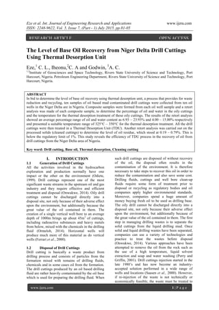
  • 2. Eze et al. Int. Journal of Engineering Research and Applications www.ijera.com ISSN: 2248-9622, Vol. 5, Issue 7, (Part - 1) July 2015, pp.01-05 www.ijera.com 2 | P a g e reduce oil concentration prior to final disposal. There is also the risk of groundwater contamination during reinjection (Meinhold, 1999). 1.3 Objective of the Study This study therefore was set to determine the level of base oil recovery using thermal desorption unit before disposing oily cuttings with particular reference to the Niger Delta area of Nigeria. It is also aimed at assessing the efficiency of low temperature thermal desorption in oil and water recovery from drill cuttings from the same region. II. METHODOLOGY 2.1 Sample Collection The oil based mud contaminated drill cuttings samples were collected from ten wells across the Niger Delta area of Nigeria. The oil contaminated drill cuttings were transported to the facility in specially designed, water-tight, leak-proof skips. 2.2 Retort Analysis Prior to Treatment A retort analysis was carried on the samples to determine the level of base oil contamination of the cuttings. Samples from the same well were bulked together to form a composite sample. A retort analysis was made of each composite sample to determine the percentage of oil and water in the oily cuttings at 345°C. 50 grams of the bulk sample was heated at 345°C for one hour, to vaporize the liquid components which were then condensed and collected in a graduated cylinder. Liquid volumes were determined from reading the oil and water phases on the graduated cylinder. The total volume of solids, both suspended and dissolved, was obtained by noting the difference of the total sample volume versus the final liquid volume collected. The percentage of oil and water in the oily cuttings were thus noted (Table 1). 2.3 Thermal Processing The samples were treated in a Thermal Desorption Unit (TDU). Thermal Desorption process is suited to processing a wide range of oil contaminated waste cuttings and extracting, through a distillation process, and recovering any hydrocarbon content, which will evaporate at temperature below 325o C. Hydrocarbons are volatized from oily solids in a closed chamber using controlled heat. The dry boiling point of base oil is 327° C (Ormeloh, 2014). However, operating the unit at a lower temperature so close to the actual boiling point of the oil would increase the required cuttings residency time in the TDU and therefore could negatively impact treatment rates. From a process perspective, the best scenario is to operate at highest possible temperature without cracking the oil. The process achieves maximum phase separation without exceeding the fractionation point of the base oil. Thermal cracking temperature is a function of molecule size. Larger molecules crack at lower temperatures. Hydrocarbons that are used as the base oil for drilling fluids contain relatively short-chain, small molecules that do not crack at the temperatures normally reached in thermal desorption units. All thermal desorption processes evaporate the oil and water from the cuttings. The heat required to evaporate the oil and water provides enough energy to remove and separate emulsified oil as well. Free and emulsified oil and water are removed by distillation, and in the process, water evaporates first to produce steam. Oil has a higher boiling point and evaporates after the water. The production of steam can also assist in lowering the boiling point of oil. The process began by the empting of the skips into the storage coral where the drill cuttings are stored before they are processed in order to return the skips and to allow for regular operation of the plant (Figure 1). The drill cuttings enters the system through a special non-plugging design feed hopper with the use of a loader. The feed hopper is equipped with a weighing device and variable speed auger-feeder that meters the material into the rotary dryer. The system can process a wide range of particle sizes from clay to rock. The exclusive, stainless steel dryer unit is designed to dry and heat the drill cuttings indirectly through conductive heat transfer. This prevents combustion gases from contacting the cuttings or the hydrocarbon/water gas stream. The externally- heated rotary dryer is sealed on either end to limit oxygen entering the system or vapor exiting the system. A special cleaning system in the dryer eliminates caking of solids and keeps the material agitated to allow for even heating. The cuttings temperature is increased to vapourize the water and hydrocarbons in the cuttings. The temperature in this particular process is 345o C.
  • 3. Eze et al. Int. Journal of Engineering Research and Applications www.ijera.com ISSN: 2248-9622, Vol. 5, Issue 7, (Part - 1) July 2015, pp.01-05 www.ijera.com 3 | P a g e Figure 1: Thermal Desorption Unit Flow Diagram The hydrocarbon and water vapours pass through a quench-scrubber for particulate removal. At the adiabatic quench, where water is sprayed on the vapour phase, converting it to liquid phase. The pre quench works on the same principle as the quench, but is designed to knock off fine dust particles earlier and pumped to the centrifuge. This stage removes any residual ultra-fine dust particles from the gas-air stream and ensures recovery of a clean, usable oil or synthetic fluid. The scrubbed oil and water gas-stream mix enters one or more condensers to return the oil and water to a liquid state. This unit is for condensing all gasses that were not condensed at the quench process. The cooling tower is a heat exchanger, which cools the water from the quench process. The thermal oxidizer unit oxidizes the mixture and destroys any non-condensable hydrocarbons and ensures clean emissions. The mixture is processed through an oil/water separator and coalesces to separate the mixture into clean water and oil, or synthetic fluid. The centrifuge is used to remove ultra-fine solids from the process while the weir tank as the name implies is made of weir plates, used for typical separation of oil and water. Oil goes on top of the weir, while water goes under. The solids are bubbled using air to the centrifuge sump where they are pumped to the centrifuge. Processed drill cuttings leaving the dryer and dust leaving the bag-house is mixed with the recovered water in the pugmill soil conditioner. The added water cools the processed cuttings and controls dust before releasing the ash into the ash pit. Processed cuttings are collected at this point and tested. The processed, conditioned cuttings can then be back- filled or transported offsite for ultimate disposal or recycling. For each 100 tons of drill cuttings treated, Ntukidemet al., (2002) estimate process recovers on the average between 10 - 15 cubic meters of oil. The recovered oil is very high quality and is suitable for in the fabrication of new drilling mud. The TDU process reduces the waste volume by approximately 20%. The recovered oil is moved to a storage tank and can be used as fuel for the primary burners, recycled into fresh drilling mud, or returned to the client.Testing of recovered base oil has shown no significant degradation or formation of new hydrocarbon chains during the thermal process (Zupan and Kapila, 2000). The water derived from the process is stored in tanks to be reused with fresh water in the process again. 2.4 Retort Analysis after Treatment Retort was repeated on the clean cutting from the TDU outlet. 50 grams of the bulk sample was heated at 350°C for one hour, to vaporize the liquid components which was then condensed and collected in a graduated cylinder. The percentage oil and water content was noted against the initial content.
  • 4. Eze et al. Int. Journal of Engineering Research and Applications www.ijera.com ISSN: 2248-9622, Vol. 5, Issue 7, (Part - 1) July 2015, pp.01-05 www.ijera.com 4 | P a g e III. RESULTS AND DISCUSSIONS The thermal desorption treatment of the drill cuttings from the ten wells is presented in Table 1 below. A comparison of the retort analysis before and after the thermal desorption treatment shows that the oil from the drill cuttings was reduced to the barest minimum level ranging from 0.19% - 0.79% which comply with the stipulated DPR regulation of 1% oil residue in clean cuttings. For every 6.8tons of drill cuttings 1m3 of base oil is recovered. This is equivalent to base oil recovery rate of 14.70m3 for every 100tons of contaminated drill cutting. This rate is considered very good when compared to the 10-15m3 estimated by Ntukidemet al., (2002) Table 1: Summary of Drill Cuttings Treatment (TDU operations results) of the Ten Oil Wells Well Names Treated cuttings (tons) Recovered oil in m3 Recovered water in m3 Recovered cleaned cuttings (tons) Oil % in cuttings before Treatment Oil % in cuttings after Treatment Well A 46.80 5.30 4.80 36.78 23.93 0.52 Well B 66.42 13.02 10.96 42.50 10.60 0.79 Well C 55.54 11.00 11.60 33.20 11.47 0.75 Well D 45.89 5.10 4.30 36.50 6.93 0.30 Well E 46.51 6.01 5.25 35.28 8.67 0.20 Well F 46.34 6.20 4.55 35.64 7.33 0.19 Well G 54.64 8.45 7.34 38.88 9.87 0.43 Well H 43.08 6.05 5.95 31.15 10.67 0.25 Well I 49.26 6.10 6.70 36.50 12.07 0.64 Well J 45.28 6.25 6.00 33.10 13.07 0.53 Total 499.76 73.48 67.50 359.53 114.61 4.60 IV. CONCLUSIONS AND RECOMMENDATIONS Critical observation of the analytical results have shown that the thermal desorption unit is one of the best technology that can be used to recover oil from drill cuttings. Apart from recovering almost 100% of oil from the drill cuttings, this process also minimizes future environmental liability, reduces land requirements and provides for waste reduction and recycling. The recovered oil is suitable for reuse in the fabrication of new drilling mud. The recovered water in most cases are being reused in moistening the dry processed clean solids to prevent dusting effect during processing. The cleaned cuttings can be reused for construction purposes and backfilling of swampy areas. It is recommended that drill cutting producing companies apply the use of Thermal Desorption Units for the treatment of their oil contaminated drill cuttings to help save cost, reduce wastes, improve public image and also save the environment from contamination. REFERENCES [1] Ferrari G., Ceccini F. and Xiao L. (2000); Drilling Wastes Treatment and Management Practices For Reducing Impact on HSE: ENI/AGIP experiences.In the proceedings of the SPE International Oil and Gas Conference and Exhibition, China, Beijing, pp. 1-11 [2] Meinhold, A.F. (1999). Framework for a Comparative Environmental Assessment of Drilling Fluids Used Offshore. In the proceedings of the 1999 SPE/EPA Exploration and Production Environmental Conference, Austin, TX, pp. 20. [3] Ntukidem, J., Anighoro, S., & Omonigho, R. (2002). Thermal Desorption as an Alternative to Cuttings Reinjection in Niger Delta Waste Management Operations. In the proceedings of the 2003 SPE International Conference on Health, Safety and Environment in Oil and Gas Exploration, Abuja, Nigeria. pp 2 – 6. [4] Odiete W.O. (1999); Environmental Physiology of Animals and Pollution. Diversified resources Ltd. Lagos, Nigeria. pp: 261. [5] Ormeloh Jan (2014);Thermomechanical Cuttings Cleaner –Qualification for Offshore Treatment of Oil Contaminated Cuttings on the Norwegian Continental Shelf and Martin Linge Case Study. http://brage.bibsys.no/xmlui/ bitstream/handle/11250/220918/Ormeloh_Jan .pdf (Accessed 26-02-2015). [6] Onwukwe S. I. (2014); Adaptation of Thermal Desorption in the Treatment of Oil Based Drill Cuttings. International Journal of
  • 5. Eze et al. Int. Journal of Engineering Research and Applications www.ijera.com ISSN: 2248-9622, Vol. 5, Issue 7, (Part - 1) July 2015, pp.01-05 www.ijera.com 5 | P a g e Engineering and Technical Research, 2(12), pp. 78-80 [7] Perry, M. L., and Griffin, J. M. (2001). Chemical Treatment of Cuttings Drilled with Oil Based Mud Employing a Laboratory Simulated Soil Washing Procedure. In the proceedings of Exploration and Production Environmental Conference, San Antonio, Texas, pp. 13 – 21 [8] Saasen, A., Paulsen, J. E. and Hoithe, K. (2000). Environmental Priorities of Re- injection and Land Based Handling of Drilled Cuttings and Affiliated Fluids. In the proceedings of the SPE International Conference on Health, Safety, and the Environment in Oil and Gas Exploration and Production, Stavanger, Norway, pp. 3 – 10 [9] Zupan, T., and Kapila, M. (2000). Thermal Desorption of Drill Muds and Cuttings in Ecuador: The Environmental and Financially Sound Solution. In the proceedings of International Conference on Health, Safety and Environment in Oil and Gas Exploration and Production, Ecuador, pp. 12-16.