

Recommended
Recommended
More Related Content
What's hot
What's hot (20)
Similar to Ijciet 06 10_008
Similar to Ijciet 06 10_008 (20)
More from IAEME Publication
More from IAEME Publication (20)
Recently uploaded
Recently uploaded (20)
Ijciet 06 10_008
- 1. http://www.iaeme.com/IJCIET/index.asp 97 editor@iaeme.com International Journal of Civil Engineering and Technology (IJCIET) Volume 6, Issue 10, Oct 2015, pp. 97-107, Article ID: IJCIET_06_10_008 Available online at http://www.iaeme.com/IJCIET/issues.asp?JType=IJCIET&VType=6&IType=10 ISSN Print: 0976-6308 and ISSN Online: 0976-6316 © IAEME Publication ANALYSIS OF EMBANKMENT SUPPORTED BY STONE COLUMNS ENCASED WITH GEOSYNTHETIC MATERIAL Asst. Prof. Dr. Qassun S. Mohammed Shafiqu Civil Engineering Department Collage of Engineering, Al-Nahrain University, Iraq Fadhl Abbas Ahmed Al-Assady Civil Engineering Department, Collage of Engineering, Al-Nahrain University, Iraq ABSTRACT Stone column is often employed for strengthening of an embankment seated on deep soft clay. But in very soft clay, stone column may not derive adequate load carrying capacity and undergo large lateral deformation because of inadequate lateral confinement. In such cases, reinforcement to individual stone column by geosynthetics enhances load caring capacity and reducing lateral deformation. In this study analysis of an embankment resting on encased stone columns ESC are investigated using the latest version of finite element program ''Plaxis 3D 2013''. Example of model prediction and accuracy of finite element formulation were given. Then the transient analysis of three-dimensional embankment problem supported on geogrid reinforced stone columns has been carried out taken in to consideration the influence of some parameters on the long-term behavior of the system, such as stone columns diameter (d), stone columns length ratio (L/d), encasement stiffness, undrianed shear strength. The results also indicated that the percentage of decrease in settlement for embankment reinforced with ESC relative to untreated embankment for (L/d=5) were (49.83 %, 43.53 %, 38.7 % and 32.63 %) for S/d (2.5, 3.0, 3.5, and 4.0); respectively. And for (L/d=8) being (68.86 %, 67.23 %, 55.48 % and 51.36 %) for S/d (2.5, 3.0, 3.5, and 4.0); respectively. And the pattern of ESC has significant influence on the settlement comparing with the effect of spacing between them. Also for (L/d = 8) the maximum horizontal deformation was observed at a depth of about 1.7d. The results showed significant decreasing in lateral displacement with increasing the diameter of encased stone columns. Also increasing the undrianed shear strength, cu by 100 % decreased the vertical settlement by
- 2. Asst. Prof. Dr. Qassun S. Mohammed Shafiqu and Fadhl Abbas Ahmed Al-Assady http://www.iaeme.com/IJCIET/index.asp 98 editor@iaeme.com about 65 % and a noticeable decrease in the lateral displacement was obtained with increasing cu. Cite this Article: Asst. Prof. Dr. Qassun S. Mohammed Shafiqu and Fadhl Abbas Ahmed Al-Assady. Analysis of Embankment Supported by Stone Columns Encased with Geosynthetic Material. International Journal of Civil Engineering and Technology, 6(10), 2015, pp. 97-107. http://www.iaeme.com/IJCIET/issues.asp?JType=IJCIET&VType=6&IType=10 INTRODUCTION Soft soils are fairly widespread all over the world and the places of them are in important cities. Geotechnical design and execution of civil engineering structures on soft to very soft soil are usually associated with essential difficulties. Two main problems are encountered when undertaking construction in soft soil layers, excessive settlement and low shear strength (Barksdale and Bachus, 1983), (Bergado et al., 1996). Embankment seated on soft clay may undergo large displacements both vertically and horizontally. A lot of soil improvement methods have been used to deal with soft soil problems. The improvement methods of the soft soil include replacement, sand drains, vacuum pressure, preloading, dynamic compaction, lime stabilization, geosynthetic reinforcement and stone or gravel columns (Kemphert and Gebresealssie, 2006). Stone columns provide an influential improvement process for soft soils under light structures such as road embankments or rail. The use of stone columns as a method of soft soil improvement has been successfully implemented around the world. The stone column technique was developed in Germany about 60 years ago (Elsawy, 2010). The use of geosynthetic encased columns provides an economic and effective solution when rapid construction and small deformation are required (Raithel et al., 2004). Geosynthetic reinforcement reduces the maximum as well as differential settlement and helps transfer stresses from soft soil to stone columns. The embankment soil in between stone columns has a tendency to settle more due to stiffness difference between stone columns and soft soil (Naughton and Kempton, 2003). Thus in this study analysis of an embankment resting on stone columns will be investigated using the finite element method. And In order to avoid dispersion of the stones into the clay and to improve the stone columns as reinforcing elements, geogrids are used in this study as a geosynthetic material encased the stone columns. Stone columns provide an influential improvement process for soft soils under light structures such as road embankments or rail. In order to avoid dispersion of the stones into the clay and to improve the stone columns as reinforcing elements, geogrids are used in this study as an encasement of the stone columns. THEORETICAL WORK Modeling Finite element mesh and boundary conditions The dimensions of soft soil and the stone columns were taken according to the experimental work by Al-Shammarie (2013) scaled by 20 and as shown in Figures (1
- 3. Analysis of Embankment Supported by Stone Columns Encased with Geosynthetic Material http://www.iaeme.com/IJCIET/index.asp 99 editor@iaeme.com and 2). Due to symmetry, only half of the embankment was modeled to save computation time. Soft soil dimensions were 30 m in x-direction, 16 m in y-direction and 11.2 m downward in z-direction. The boundary effect was investigated indicating that it would be sufficient to eliminate its effect if the boundary was set at 18 m from the toe. The stone columns length is taken equal to L=5d and L=8d where d is the stone columns diameter, in some cases a geogrid material has been added as encasement for stone columns. As seen in the figures, a 12 m wide embankment having side slope 1V: 1.2H and height H=2 m resting on 11.2 m soft clay underlaying by rigid layer is constructed in two layers, each layer constructed in 30 days, the first layer 1 m depth was consolidated for further 30 days while the consolidation of the second layer was continued till excess pore water pressure reached near 1 kPa, The phreatic level was set at the top surface of the soft clay layer to generate a hydrostatic pore water pressure profile in the domain. In this study, settlement and excess pore water pressure are observed for reference points A and B, respectively, as shown in Figure (2). Also, lateral displacement was computed for the extreme left stone column. Due to the large model’s dimensions, medium mesh was created and refining at the stone columns and the surrounding area to allow for the use of small time step (i.e. 0.001 day onward) to achieve greater accuracy in the beginning of consolidation progress. The mesh consists of nearly 33,250 elements (10-node tetrahedrons) with over 46,000 nodes Figure (3). Figure 3 Elements volume in three-Dimensional finite element mesh Figure 1 Cross section and measurement points for embankment supported on stone columns Figure 2 Three-Dimensional finite element modeling of embankment supported on stone columns
- 4. Asst. Prof. Dr. Qassun S. Mohammed Shafiqu and Fadhl Abbas Ahmed Al-Assady http://www.iaeme.com/IJCIET/index.asp 100 editor@iaeme.com Constitutive models and material parameters An elasto-plastic analysis was conducted to simulate an embankment resting on ordinary stone columns (OSC) and encased stone columns (ESC). Hardening Soil model (HS) was used to simulate the soft soil and embankment fill material, while the stone columns volumes were modeled by Mohr-Coulomb model (MC). These constitutive models were verified with experimental results of Al-Shammarie (2013). Parameters for the bench mark case are mentioned in Table (1), these parameters adopted in this numerical analyses are taken from Al-Shammarie (2013) experimental work. Reinforce stone column by geosynthetics enhance load carrying capacity and reduces lateral deformation. The geogrid is selected as geosynthetic encasement and is modeled as a linear elastic. Two interfaces were product for each encasement, the first outside the geogrid (positive interface) between geogrid and soft soil carrying the soft soil properties, and the second one inside the geogrid (negative interface) between geogrid and stone column carrying the stone column properties. Interfaces are composed of 12-node elements consisting of six pairs of nodes, which are compatible with the 6-noded triangular sides of the soil (Brinkgreve et al, 2013). Table 1 Parameters for the benchmark case adopted in the numerical analyses. Properties Soft clay Embankment fill Stone column Unsaturated unit weight, γunsat (kN/m3 ) 13.24 21.83 14.4 Saturated unit weight ,γsat (kN/m3 ) 18.85 24.22 15.7 Material model Hardening soil Hardening soil Mohr-Coulomb Initial void ratio, e˳ 0.92 0.16 0.5 Drainage type Undrained Drained Drained E (kPa) - - 150000 E50 ref (kPa) 600 10000 - Eoed ref (kPa) 1425 10000 - Eur ref (kPa) 1800 30000 - Power (m) 1 1 - Cohesion ,C (kPa) 10 1 1 Friction angle ,Ø (deg) - 40 41.5 Poisson’s ratio, ν 0.35 0.3 0.3 Permeability kx=ky=kz (m/day) 8.640 x 10⁻⁵ 0.6 0.6 Geosynthetic stiffness, (kN/m) - - 1000 NUMERICAL ANALYSIS PROCEDURE The reinforced soft soil with encased stone columns has been investigated by using an elastic perfectly plastic finite element analysis which involves a several of steps or phases. The numerical modeling consisted of three steps: initial geostatic equilibrium, inserting the ordinary stone columns or encased stone columns, construction of embankment and long term time depending phase. First step is the generation of initial stress and pore water pressure, the initial stresses had been generated using the K˳ procedure calculation type. The K˳ procedure is used in case with a horizontal surface and with all soil layers and phreatic levels parallel to the surface, the phreatic level was set at the top surface of the soft clay layer.
- 5. Analysis of Embankment Supported by Stone Columns Encased with Geosynthetic Material http://www.iaeme.com/IJCIET/index.asp 101 editor@iaeme.com The second step is modeling stone column by replacing soft soil elements by stone column, in some cases, the geosynthetic reinforcement and interface elements was added as wished in place. Plastic calculation type was used in this step. The third step is modeling embankment’s two layers, the first layer with 1 m depth is constructed in 30 days and consolidated for further 30 days while the second layer with 1 m depth will be constructed in 30 day and the consolidation continued till excess pore water pressure reached near 1 kPa. Consolidation calculation type was used in this step which is time-dependent analysis of deformation and excess pore water pressures. Input of soil permeability required. Also, non-zero time interval will be used. PARAMETRIC STUDY 1. Effect of diameter of stone column In order to investigate the effect of diameter of encased stone column on long-term behavior, the stone column center-to-center spacing of 3.5 m, the stone column length L=7 m, stone columns diameter (d = 0.8 m, 1 m, 1.1 m, 1.2 m, 1.3 m and 1.4 m) given in Figure (4). Figure 4 Pattern of encased stone columns at different spacing (L/d=5). 2. Effect of L/d ratio of encased stone columns To understand the long-term behavior for encased stone column supported embankments, the effect of change in stone columns length has been investigated, the stone columns diameter (d = 1.4 m), the stone column spacing to diameter S/d =2.5, the stone column length to diameter (L/d =5 and 8) shown in Figures (4, 5, and 6). Figure 5 Cross section for embankment supported on encased stone columns (L/d=5). Figure 6 Cross section for embankment supported on encased stone columns (L/d=8).
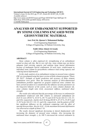
- 6. Asst. Prof. Dr. Qassun S. Mohammed Shafiqu and Fadhl Abbas Ahmed Al-Assady http://www.iaeme.com/IJCIET/index.asp 102 editor@iaeme.com 3. Effect of encasement stiffness of stone columns To understand the long-term behavior for encased stone column supported embankments, the influence of geosynthetic stiffness has been investigated, the encased stone columns diameter (d = 1.4 m), the stone column length to diameter (L/d =5), J (kN/m) =1000, 1500, 3000, 5000, 7000, 8000, and 10000. 4. Effect of the undrianed shear strength (cu) The influence of undrained shear strength has been investigated on ordinary stone columns, the ordinary stone columns diameter (d = 1.4 m), the stone column length to diameter (L/d =5), the stone column spacing with respect to diameter S/d =2.5, the shear strength (kPa) =7.5,10,12.5 and 15. RESULT AND CONCLUSION 1. Effect of diameter of stone column The percentage of decrease in settlement for embankment reinforced with ESC relative to untreated embankment were (29.43 %, 30.47 %, 37.96 %, 41.15 %, 44.84 % and 49.83 %) for diameter (8.0, 1.0, 1.1, 1.2, 1.3 and 1.4 m); respectively. Also the results showed significant decreasing in lateral displacement with increasing the diameter of encased stone columns. The maximum lateral displacementoccur at the tip of columns for L/d=5, and that 1.4 m diameter gives the lowest lateral displacement. The encasement of stone columns decrease the lateral displacement on corner columns as the encasement prevent the stone column from side moving. Also increasing diameter lead to decrease the excess pore water pressure at the construction stages. As shown in Figures (7, 8, and 9). Figure 7 Settlement of embankment with different diameter of encased stone columns. 0.35 0.37 0.39 0.41 0.43 0.45 0.47 0.49 0.51 0.53 0.7 0.9 1.1 1.3 1.5 surfacesettlement(m) Diameter (m)
- 7. Analysis of Embankment Supported by Stone Columns Encased with Geosynthetic Material http://www.iaeme.com/IJCIET/index.asp 103 editor@iaeme.com Figure 8 Lateral displacement of ordinary and encased stone column with different diameter. Figure 9 Excess pore water pressure versus time with different diameter for (L/d=5) 2. Effect of L/d ratio of encased stone columns There are high decreasing in vertical settlement when increasing the stone columns length (L/d). The end bearing for ESC with (L/d = 8) exhibits a vertical settlement (1.45 to 1.7) times that of floating column with (L/d = 5). The maximum lateral displacement occur at the tip of columns for L/d=5, and the percentage of decrease in lateral displacement for embankment reinforced with ESC with L/d=8 relative to that with L/d=5 (75.30 %, 68.67 %, 67.68 % and 62.34 %) for S/d (2.5, 3.0, 3.5, and 4.0); respectively. And increase L/d decrease excess pore water pressure at end of construction. The decreasing in pore water pressure percentage for embankment reinforced with ESC with L/d= 8 relative to that with L/d = 5 at the end of construction were (21.77 %, 21.33 %, 12.52 % and 13.99 %) for S/d (2.5, 3.0, 3.5, and 4.0); respectively. Figures (10, 11, and 12) 7.00 6.00 5.00 4.00 3.00 2.00 1.00 0.00 0.15 0.2 0.25 0.3 0.35 0.4 Depth(m) Lateral displacement (m) ESC 0.8 m ESC 1.0 m ESC 1.1 m ESC 1.2 m ESC 1.3 m ESC 1.4 m
- 8. Asst. Prof. Dr. Qassun S. Mohammed Shafiqu and Fadhl Abbas Ahmed Al-Assady http://www.iaeme.com/IJCIET/index.asp 104 editor@iaeme.com Figure 10 Settlement of embankment with different S/d for embankment resting on encased stone columns in different lengths. Figure 11 Excess pore water pressure versus time with different L/d and S/d ratio for embankment resting on encased stone columns. Figure 12 Lateral displacement of encased stone column with different L/d and S/d ratios. 0.1 0.2 0.3 0.4 0.5 0.6 2 2.5 3 3.5 4 4.5 surfacesettlement(m) S/D l/d=5 l/d=8 7.00 6.00 5.00 4.00 3.00 2.00 1.00 0.00 0.05 0.1 0.15 0.2 0.25 0.3 Depth(m) Lateral displacement (m) L/d=5,S/d=4 L/d=5,S/d=3.5 L/d=5,S/d=3 L/d=5,S/d=2.5 L/d=8,S/d=2.5 L/d=8,S/d=3.0 L/d=8,S/d=3.5 L/d=8,S/d=4.0
- 9. Analysis of Embankment Supported by Stone Columns Encased with Geosynthetic Material http://www.iaeme.com/IJCIET/index.asp 105 editor@iaeme.com 3. Effect of encasement stiffness of stone columns The vertical settlement decrease with increasing the geogrid stiffness (J), when J equal to (1000, 1500, 3000, 5000, 7000, 8000, and 10000) kN/m the vertical settlement were (0.392, 0.392, 0.380, 0.378, 0.375, 0.374, and 0.372) m; respectively as shown in Figure (13). Also there is improvement in lateral displacement with increasing J, Figure (14). Figure 13 Settlement of embankment with different geogrid stiffness Figure 14 Lateral displacement for different encasement stiffness J, L/d=5. 4. Effect of the undrianed shear strength (cu) Increasing the undrianed shear strength cu by 100 % decrease the vertical settlement by about 65 % and a noticeable decrease in the lateral displacement is obtained with increasing cu, when the value of cu is equal and greater than 10 kPa, a significant improvement of lateral displacement is clearly noticed. Also the excess pore water pressure increase with decreasing the undrianed shear strength. Figures (15, 16, and 17) 0.37 0.375 0.38 0.385 0.39 0.395 0 2000 4000 6000 8000 10000 12000 surfacesettlement (m) Geogrid stiffnes (kN/m) 7.00 6.00 5.00 4.00 3.00 2.00 1.00 0.00 0.15 0.17 0.19 0.21 0.23 0.25 Depth(m) Lateral displacement (m) J=1000 kN/m J=1500 kN/m J=3000 kN/m J=5000 kN/m J=7000 kN/m J=8000 kN/m J=10000 kN/m
- 10. Asst. Prof. Dr. Qassun S. Mohammed Shafiqu and Fadhl Abbas Ahmed Al-Assady http://www.iaeme.com/IJCIET/index.asp 106 editor@iaeme.com Figure 15 Settlement of embankment with different undrianed shear strength Figure 16 Lateral displacement for different undrianed shear strength. Figure 17 Excess pore water pressure versus time with different shear strength 0 0.2 0.4 0.6 0.8 1 6 8 10 12 14 16 Surfacesettlement(m) Undrianed shear strength cu (kPa) 7.00 6.00 5.00 4.00 3.00 2.00 1.00 0.00 0.00 0.10 0.20 0.30 0.40 0.50 0.60 0.70 Depth(m) Lateral displacement (m) Cu=7.5 kPa Cu=10 kPa Cu=12.5 kPa Cu=15 kPa
- 11. Analysis of Embankment Supported by Stone Columns Encased with Geosynthetic Material http://www.iaeme.com/IJCIET/index.asp 107 editor@iaeme.com REFERENCES [1] Al-Shammarie H. A. (2013), An Experimental and Theoretical Study on Ordinary and Encased Stone Columns Underneath Embankment", Ph.D. Thesis, Civil Engineering Department, University of Baghdad, Iraq. [2] Bergado, D.T., Anderson, L.R., Miura, N. and Balasubramaniam, A.S., (1996), "Soft ground improvement in lowland and other environments, ASCE press, New York, USA: pp 427 pp. [3] Barksdale, R.D. and Bachus, H.G., (1983), "Design and construction of stone columns", Dept. of Transpiration, Federal Highway Administration Report, USA report No. FHWA/RD 83/026. [4] Brinkgreve, R. B. J., Engin, E., Swolfs, W. M., editors. (2013). Plaxis 3D 2013 tutorial manual. [5] Elsawy, M. B. (2010), " Highway Embankment Constructed on Soft Soil Improved by Stone Columns with Geosynthetic Materials", Ph.D. Thesis, Institute of Geotechnical Engineering, Department of Civil Engineering, Faculty of Engineering, Duisburg-Essen University. [6] Kempfert, H-G, Gebreselassie, B. (2006), "Excavations and Foundations in Soft Soils", Universitat Kassel, FG Geotechnik. Monchebergstr. 7, 34125 Kassel, Germany. [7] Naughton, P. and Kempton, G. (2003), "A New Design Procedure for Piled Embankments", Proceedings of the 56th Canadian Geotechnical Conference and the NAGS Conference, Winnipeg, MB, pp. 858-865. [8] Raithel M, Küster V, Lindmark A (2004), "Geotextile encased columns – a foundation system for earth structures", Illustrated by a dyke project for a works extension in Hamburg. Nordic Geotechnical Meeting 2004, Sweden. [9] V.K.Chakravarthi K.Ramu M.R.Madhav, Slope Stability Analysis of Basal Reinforced Embankment under Oblique Pull. International Journal of Civil Engineering and Technology, 1(1), 2010, pp. 1 - 14. [10] Esraa A. Mandhour, Saad N. Al-Saadi, Saad F. Ibrahim, Study of the Efficiency of Stone Columns In Soft Clay: Considering The Effect Of Clay Minerals In Soil. International Journal of Civil Engineering and Technology, 5(9), 2014, pp. 241 - 251.