![HBRP Publication Page 1-22 2023. All Rights Reserved Page 2
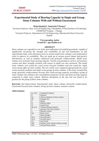
Journal of Advances in Geotechnical Engineering
Volume 6 Issue 1
DOI: https://doi.org/10.5281/zenodo.7736100
INTRODUCTION
In soft soil, the creation of stone columns
results in increased load-carrying capacity
and stiffness, as well as a reduction in
consolidation settlement. Numerous
researchers have attempted to investigate
various aspects of stone columns. They
investigated the workability of stone
columns in a variety of soil samples,
including clay samples [1–4], soft clay
foundations [5, 6], layered soil [7], and
sand confined with single and multiple
geocells. Furthermore, numerical studies
on stone columns were carried out [8–10].
Inadequate lateral support in soft soils
significantly reduces the effectiveness of
stone columns. This lateral confinement
insufficiency is most common at shallow
depths, resulting in bulging failure of the
upper half of the columns. For the first
time, Huges and Withers [11] explain this.
In these circumstances, encasing the
column in various types of geotextile
improves the behavior of the stone
column. As a result, different
investigations on the behavior of
encapsulated stone columns have been
done, including experimental tests,
theoretical and numerical analysis, and
field applications. Some of them are
discussed in this article.
Small scale laboratory tests have been
used to conduct experiments, with the
majority of the focus being on the analysis
of load-settlement behavior [12–15].
Because one of the primary constraints of
stone columns is failure during loading,
various failure mechanisms, such as
bulging failure, shear failure, and punching
failure, have been studied in other studies,
such as those presented by Ali et al. [16,
17] or Chen et al. [18]. For these
experimental studies, the sleeves were
primarily made of geotextiles through a
sewn overlap of the fabric (e.g. Murugesan
and Rajagopal [19, 20] or a glued overlap
of the fabric) (e.g. Gniel and Bouazza
[21]). Yoo and Lee [22] studied the
performance of encased stone columns in
soft ground with full-scale load tests in the
field, in addition to small-scale laboratory
tests.
Other studies use triaxial compression tests
of encased samples, such as Sivakumar et
al. [23], who used stone columns to
reinforce clay samples with diameters and
depths of 300 and 400 mm, respectively, in
a large triaxial cell under a confining
pressure of 50 kPa. Wu and Hong [24] also
conducted triaxial compression tests on
reinforced and non-reinforced columns,
primarily to assess the effect of the
encasement on the radial strains of the
sample and the deviator stress. The same
procedure was used by Najjar et al. [25] to
examine normally consolidated kaolin
samples reinforced with single sand
columns. Furthermore, Kim and Lee [26]
conducted some tests using a centrifuge.
A study based on a compression test is
performed by plate loading test in this
paper to supplement the understanding of
stone column behavior in a more
rewarding way. This test is performed on
columns containing various geotextiles,
group of stone columns and cased versus
uncases stone column study. The effect of
moisture change due to installation of
stone columns for various combinations
were analyzed.
EXPERIMENTAL STUDY
In the present study, model test will be
carried out on the long end-bearing single
and groups of stone-columns with and
without reinforcement to evaluate the
relative improvement in the failure stress
of the stone-column reinforced Kaolinite
clay bed. This will be done also by
performing tests on three different kinds of
geo-textile materials.](data:image/gif;base64,R0lGODlhAQABAIAAAAAAAP///yH5BAEAAAAALAAAAAABAAEAAAIBRAA7)
Recommended
Recommended
More Related Content
Similar to Experimental Study of Bearing Capacity in Single and Group Stone Columns With and Without Encasement.pdf
Similar to Experimental Study of Bearing Capacity in Single and Group Stone Columns With and Without Encasement.pdf (20)
More from Samirsinh Parmar
More from Samirsinh Parmar (20)
Recently uploaded
Recently uploaded (20)
Experimental Study of Bearing Capacity in Single and Group Stone Columns With and Without Encasement.pdf
- 1. HBRP Publication Page 1-22 2023. All Rights Reserved Page 1 Journal of Advances in Geotechnical Engineering Volume 6 Issue 1 DOI: https://doi.org/10.5281/zenodo.7736100 Experimental Study of Bearing Capacity in Single and Group Stone Columns With and Without Encasement Mehul Katakiya1 , Samirsinh P Parmar2 1 Assistant Professor, Dept. of Civil Engineering, Chandubhai S Patel Institute of Technology, CHARUSAT Campus – Changa. 2 Assistant Professor, Department of Civil Engineering, Dharmasinh Desai University, Nadiad. *Corresponding Author E-mail Id: - spp.cl@ddu.ac.in ABSTRACT Stone columns are regarded as one of the most influential soil-stabilizing methods, capable of significantly increasing the strength and workability of soft soil foundations. In this experimental study, some laboratory tests on various model stone columns were performed in order to improve its workability. They are made up of various gravel shapes and particle distributions, as well as columns reinforced with geotextile reinforcements. Model stone column were tested for load carrying capacity. Various soil parameters such as soil moisture content and shear strength variation with respect to depth was also measured. The model stone columns were tested for cased versus uncased condition and also tested for single versus group effect of stone column. The test results were compared appropriately for cased versus uncased condition and single versus group of stone columns. It has been revealed that using, geotextile reinforcements increase their load-carrying capacity, providing a group of stone columns also enhances the consolidation properties of clay and load carrying capacity compared to single stone column. Moisture dissipation in the clay bed was found to be greatest for the group of three stone columns. Keywords: Soil improvement, Experimental study, Stone column, Geotextile reinforcement, Cased and Uncased stone columns, Group of stone columns, moisture content. Abbreviations: Cu or Su Undrained Cohesion D Diameter De effective diameter of stone column GP Granular Pile H Height Ip Plasticity Index LL Liquid Limit Qu or Q Ultimate Bearing Capacity S spacing of the stone columns w Moisture content Wp Plastic Limit ξ Shear Strength GG-1 Geo-grid type-1 GG-2 Geo-grid type-2 GT Geo-Textile OSC Ordinary stone column (without casing) ESC Encased Stone column
- 2. HBRP Publication Page 1-22 2023. All Rights Reserved Page 2 Journal of Advances in Geotechnical Engineering Volume 6 Issue 1 DOI: https://doi.org/10.5281/zenodo.7736100 INTRODUCTION In soft soil, the creation of stone columns results in increased load-carrying capacity and stiffness, as well as a reduction in consolidation settlement. Numerous researchers have attempted to investigate various aspects of stone columns. They investigated the workability of stone columns in a variety of soil samples, including clay samples [1–4], soft clay foundations [5, 6], layered soil [7], and sand confined with single and multiple geocells. Furthermore, numerical studies on stone columns were carried out [8–10]. Inadequate lateral support in soft soils significantly reduces the effectiveness of stone columns. This lateral confinement insufficiency is most common at shallow depths, resulting in bulging failure of the upper half of the columns. For the first time, Huges and Withers [11] explain this. In these circumstances, encasing the column in various types of geotextile improves the behavior of the stone column. As a result, different investigations on the behavior of encapsulated stone columns have been done, including experimental tests, theoretical and numerical analysis, and field applications. Some of them are discussed in this article. Small scale laboratory tests have been used to conduct experiments, with the majority of the focus being on the analysis of load-settlement behavior [12–15]. Because one of the primary constraints of stone columns is failure during loading, various failure mechanisms, such as bulging failure, shear failure, and punching failure, have been studied in other studies, such as those presented by Ali et al. [16, 17] or Chen et al. [18]. For these experimental studies, the sleeves were primarily made of geotextiles through a sewn overlap of the fabric (e.g. Murugesan and Rajagopal [19, 20] or a glued overlap of the fabric) (e.g. Gniel and Bouazza [21]). Yoo and Lee [22] studied the performance of encased stone columns in soft ground with full-scale load tests in the field, in addition to small-scale laboratory tests. Other studies use triaxial compression tests of encased samples, such as Sivakumar et al. [23], who used stone columns to reinforce clay samples with diameters and depths of 300 and 400 mm, respectively, in a large triaxial cell under a confining pressure of 50 kPa. Wu and Hong [24] also conducted triaxial compression tests on reinforced and non-reinforced columns, primarily to assess the effect of the encasement on the radial strains of the sample and the deviator stress. The same procedure was used by Najjar et al. [25] to examine normally consolidated kaolin samples reinforced with single sand columns. Furthermore, Kim and Lee [26] conducted some tests using a centrifuge. A study based on a compression test is performed by plate loading test in this paper to supplement the understanding of stone column behavior in a more rewarding way. This test is performed on columns containing various geotextiles, group of stone columns and cased versus uncases stone column study. The effect of moisture change due to installation of stone columns for various combinations were analyzed. EXPERIMENTAL STUDY In the present study, model test will be carried out on the long end-bearing single and groups of stone-columns with and without reinforcement to evaluate the relative improvement in the failure stress of the stone-column reinforced Kaolinite clay bed. This will be done also by performing tests on three different kinds of geo-textile materials.
- 3. HBRP Publication Page 1-22 2023. All Rights Reserved Page 3 Journal of Advances in Geotechnical Engineering Volume 6 Issue 1 DOI: https://doi.org/10.5281/zenodo.7736100 Table 1:-Proposed Scheme of Investigation Sr. No. Figure Number Abbreviation Description of With/Without Casing Plate Load Tests 1 Figure- 1.2 A Single stone-column Without Geo-textile (WGT) 2 B Group of 3 stone-columns 3 A-1 Single stone-column With Geo-grid type-1 (GG-1) 4 B-1 Group of 3 stone-columns 5 Figure1.3 A-2 Single stone-column With Geo-grid type-2 (GG-2) 6 B-2 Group of 3 stone-columns 7 A-3 Single stone-column With Geo-textile (GT) 8 B-3 Group of 3 stone-columns Table 1 denotes the experimentation schedule for different combinations of model test on stone columns and Figure -1 indicates the arrangement of model stone columns in the test tank. The test tank is made up of precast RCC pie section, impervious from sides possess reasonably good stiffness due to the hoop stress. Fig1.1:-Plane view of tank (all dimensions are in mm) Fig.1.2:-Investigation-I Fig.1.3:-Investigation-II Fig.1:-Schematic diagram for stone column model testing. Figure 2 depicts the typical test arrangement of different materials inside the test tank to carryout model stone column experiments. The Section views of uncased stone column Section views of encased stone column Fig.2:-Typical arrangement of Stone columns into the test tank.
- 4. HBRP Publication Page 1-22 2023. All Rights Reserved Page 4 Journal of Advances in Geotechnical Engineering Volume 6 Issue 1 DOI: https://doi.org/10.5281/zenodo.7736100 PHYSICAL MODELS Figure: Geogrid wrapped around pipe Figure: Bottom piece of Geogrid for encased stone column. Fig.3:-Geotextile wrapped around PVC pipe to install encased model test tank. Test Materials Soils The basic soil properties such as Liquid Limit, Plastic Limit, Maximum Dry Density and Optimum Moisture Content were investigated for kaolinite soil. The properties of the Kaolinite clay are depicted in table-2 and MDD-OMC curve is shown in figure-4. Table 2:-Property of clay Sr. No Parameters for clay Properties of clay 1 Type of Clay Kaolinite Clay 2 Specific gravity (%) 2.56 3 Liquid limit (Wl) (%) 59.7 4 Plastic limit (Wp) (%) 26.91 5 Soil classification CH 6 Maximum dry density(gm/cc) 1.51 7 Optimum moisture content (%) 24 8 Free swell (%) 7.5 9 Shrinkage limit 25 Fig.4:-MDD -OMC curve for kaolinite soil. 1 1.1 1.2 1.3 1.4 1.5 1.6 10 15 20 25 30 35 Dry unit weight (gm/cc) Water Content (%) MDD-OMC Curve MDD=1.51 OMC = 24
- 5. HBRP Publication Page 1-22 2023. All Rights Reserved Page 5 Journal of Advances in Geotechnical Engineering Volume 6 Issue 1 DOI: https://doi.org/10.5281/zenodo.7736100 Property of Granular Material Gravel from locally available quarry site was used as a stone column fill material. Table-3 shows the properties of gravel. Table 3:-Properties of granular material Sr. No. Parameter of sand Value 1 Angle of internal friction (degree) 45° 2 Particle size (mm) 1 to 4.75 3 Dry density (KN/m3) 17.5 Geotextiles Geo-textiles were procured from Giridhar, Tec.Feb.Pvt.Ltd. from Ahmadabad. Open glass fiber grid manufactured in stable construction and is coated with modified elastomeric polymer along with self- adhesive backing as option. The melting point of coating and glass fibers are > 250° and >820° respectively. The geotextile material was tested as per standard guideline satisfying ASTM standards. Table 4:-Geogrid specifications. Type of grid Geo-Grid-1 (GG- 1) Geo-Grid-2 (GG- 2) Test direction MD CD MD CD Aperture size (mm) 9×9 9×9 Gauge length (mm) 100 100 100 100 Rib Width (mm) 4 1.9 4 1.9 Thickness (mm) 0.6 0.67 0.6 0.67 Maximum load (kN) 0.5 0.9 1.3 0.9 Deflection at maximum load (mm) 2.3 5.9 3 5.5 Stress at maximum load (N/mm2 ) 80.1 137.7 170.1 114.2 % Strain at maximum load 2.3 5.9 3 5.5 Work to maximum load (J) 0.5 1.4 2.1 3 Stiffness (N/mm) 296.2 365.4 585.6 424.9 Young's modulus (N/mm2 ) 4686.3 5448.7 7546.4 5476.1 Load at break (kgf) 20.6 35.5 89.2 34.2 Deflection at break (mm) 2.4 6.1 10 13.8 Stress at break (MPa) 32.1 55.1 112.8 43.3 Tests performed on geotextile Random sampling done from the geotextile roll and was tested for different properties of geotextile. Physical and mechanical properties of geotextile materials, such as thickness, aperture size, gauge length and stiffness, ultimate load, young’s modulus, deflection at break etc. were measured and compared for both Geo-grid-1 and geogrid-2 which is shown in table-4. Figure-6 describes the testing procedure for geogrid-1, geotextile material.
- 6. HBRP Publication Page 1-22 2023. All Rights Reserved Page 6 Journal of Advances in Geotechnical Engineering Volume 6 Issue 1 DOI: https://doi.org/10.5281/zenodo.7736100 Single strip test on Geo grid Wide width test Thickness measurement Fig.6:-Various tests performed on geotextiles Seam Strength of Geotextile When Geotextiles are sewn, the seam strength plays an important role, so after determining the elastic modulus of Geotextiles, a cube test is performed to determine the seam strength of Geotextiles, and this cube test is also performed with different densities. The seam strength is evaluated using the CBR test apparatus. The encased stone cube is put in the center of two circular plates in such a way that load is transferred vertically at a rate of 1.25mm/min, as shown in fig.-7 (a) & (b). After achieving its maximum strength, the cube begins to take load, as shown in the figure-7. The density graph (figure-8) shows that the load is the same, but deformation is less when density is higher. Fig.7:-Setup Arrangement for Compression Test on model stone column under CBR apparatus The deformation of GG-1 is less compared to GG-2, for compression test carried out in CBR apparatus. It is evident that more the tensile strength of geogrid, more load it can take under radial stresses. Seam strength is important for the geosyhthetically encased stone column, as the fill material inside the stone column remains intact.
- 7. HBRP Publication Page 1-22 2023. All Rights Reserved Page 7 Journal of Advances in Geotechnical Engineering Volume 6 Issue 1 DOI: https://doi.org/10.5281/zenodo.7736100 Fig.8:-Load versus deformation for different geotextile material under CBR test. Loading device Fig.5:-Schematic AutoCAD diagram of loading device. Clay bed preparation • Mixing: - First of all the Powdered Kaolinite Clay is taken and mixed with the water, about double the liquid limit, to form slightly stiff slurry. (figure-9, step-7) • Sieving: - The slurry is then passed through “M.S. SIEVE”, to form a uniform, lump-free and air free paste of clay. (figure-9, step-10) • Filling: - Then the slurry is filled into the RCC tank, having slotted bottom, and allowed to consolidate under its own weight for ten days and then it is covered with aluminum plate, having radial holes. • Consolidation: - After that the uniform dead load is applied on that plate for further consolidation of clay. The slotted bottom allows the water to squeeze out from the lower portion of the soil, and similarly the radial holes of aluminum plate allow from the upper portion of the soil. The consolidation is applied in incremental order as shown in table-5. • Measurement: - After 1 month of loading the plate is removed from the top plate is removed and water content and vane shear strength is measured. • Covering: - After the measurement of water content, the top of soil cake is covered with the polythene sheet, to maintain the water content same throughout the experimental schedule. After completing the process of sample preparation, the casting of stone column is 0 2 4 6 8 10 12 14 16 18 20 0 200 400 600 800 1000 1200 1400 1600 1800 Settlement (mm) Load (kg) GG-2 GG-1
- 8. HBRP Publication Page 1-22 2023. All Rights Reserved Page 8 Journal of Advances in Geotechnical Engineering Volume 6 Issue 1 DOI: https://doi.org/10.5281/zenodo.7736100 started by rammed aggregate method as shown in figure-11. The plate load test was performed (section 3.7) to find the ultimate bearing capacity. Step-1 Cleaning inside the test tank Step-2 Installation of porous stone Step-3: Laying a filter paper Step-4: Sand layer preparation Step-5: Laying filter paper Step-6: Slurry filter preparation Step-7: Mixing of clay and water Step-8: Clay slurry filtered and dropped inside the tank Step:9 Slurry dropped inside the test tank Step-10 Tank filled up to top level Step-11: Slurry tank left for consolidation Fig.9:-Step wide preparation of test bed of kaolinite clay.
- 9. HBRP Publication Page 1-22 2023. All Rights Reserved Page 9 Journal of Advances in Geotechnical Engineering Volume 6 Issue 1 DOI: https://doi.org/10.5281/zenodo.7736100 Initial loading stages The dead load is applied on the clay slurry, to achieve actual field condition. For this purpose, the sample is initially loaded in a cumulative stress as shown in this table. Figure 10 represents the step wise loading of the clay bed. Table 5:-Load applied for consolidation Sr. No. Cumulative stress (kN/m²) Area of tank (m²) Cumulative of load (kN) Load (kN) 1 0.98 0.64 0.62 0.62 2 1.96 1.25 0.62 3 3.92 2.50 1.25 4 7.85 4.99 2.50 5 9.81 6.24 1.25 TOTAL OF LOAD (kN) 6.24 (a) 1st Loading Stage (b) 2nd Loading Stage (c) Final Loading Stage Fig.10:-One Dimensional Consolidation test set-up. Procedure for installation of stone column: Without encasement Step-1. Placing of Casing-Pipe in to Sample: After preparation of the soil sample into the 900 mm diameter tank, the casing pipe is inserted into 1 of the 4 portions. Step-2. Removal of clay from Casing- Pipe: Then by using the clay removal spoon the clay is removed from the casing pipe. After removing all the clay, the pipe is cleaned using the cotton cloth. Step-3. Pouring of First Layer of Aggregate: After removal of clay and cleaning the casing pipe, the next phase of filling the casing pipe is started. For this the funnel is used. Then aggregate of fixed quantity, for first layer, is taken and start pouring it into the casing pipe. The size of aggregate should be such that there must be 8-10 particles around the periphery of casing pipe. Here we are using 4.75mm to 12mm size particles, to form stone column.
- 10. HBRP Publication Page 1-22 2023. All Rights Reserved Page 10 Journal of Advances in Geotechnical Engineering Volume 6 Issue 1 DOI: https://doi.org/10.5281/zenodo.7736100 Step-4. Partial Withdrawal of Casing Up to Predetermined Depth with Ramming: After filling aggregates for first layer the rammer of 2.6 kg is taken and 25 no’s of blows are applied on it, simultaneously the casing pipe is partially removed for predetermined depth. The blows are distributed equally over the whole area inside the pipe and care should be taken that the blows applied should be perfectly in vertical direction. Step-5. Stone Column Ready after Full Withdrawal of Casing-Pipe: Similarly required quantities for 4-5 layers are taken in step by step pouring of aggregate and removal of casing pipe is carried out, and blows of hammer are applied on each of the layers. This is done till we reach to the top and the stone column. WITH ENCASEMENT In case of the encased stone column, before installing the encased column, we need to convert the Geotextiles in circular shape so in case of geogrid the ARALITE are used to form a circular shape and in case of Geotextiles the nylon string is used. Here the perimeter length of geotextile or geogrid is 280 mm and overlap length is 25% of total perimeter length are taken to form a 70 mm diameter circular shape. Stepwise installation procedure for encased stone column; To form 80 mm diameter cased stone column, first larger diameter casing pipe of 84 mm inserted perfectly vertical into the soil sample. The same was removed with soil. after that 78 mm diameter pipe was taken and geotextile material was wrapped around its periphery considering the seam strength of geotextile material. The same was inserted to full height of stone column (i.e., 570mm). After ensuring encapsulation of geotextile with surrounding clay material, the casing pipe was removed without disturbing the geotextile material. then granular material as specified was filled equal to the top level of clay layer at a density of 2 gm/cc. Ramming wad done by steel hammer to achieve uniform density throughout the height of stone column. Proper care was taken while doing the ramming of coarser fill material, so that the geotextile material will not fail. (a) Insertion larger diameter pipe (b) Insertions of main casing with wrap GG (c) Installed single encased stone column (d) Installed groups of three columns Fig.11:- Step by step installation of encased stone column.
- 11. HBRP Publication Page 1-22 2023. All Rights Reserved Page 11 Journal of Advances in Geotechnical Engineering Volume 6 Issue 1 DOI: https://doi.org/10.5281/zenodo.7736100 ANALYSIS & DISCUSSION OF EXPERIMENTS Different gravel density The density of fill material inside the stone columns plays important role to improve the bearing capacity. To ensure the behavior of stone columns deformation with respect to density of fill material, the granular material was filled at 1.97 gm/cc, 2.0 gm/cc and 2.1 gm/cc density into the geo-grid encasement and then tested under CBR apparatus. Load vs deformation behavior was measured up to 15 mm deformation. It is observed that the stone column filled with higher density of material fill able to sustain more load and less settlement. To achieve uniformity for the density of fill material 2.0 gm/cc was adopted in the current experimentation. Fig.12:-Load Vs settlement for different density of gravel filled inside the encased stone column. Shear strength of soil Before starting the casting of the stone column in situ shear strength is measured using vane shear test apparatus. Here the rectangle vane having four sleeves are welded at a 90˚ angle and total height of the needle is about 80cm. The apparatus is arranged on the top of the tank and the needle is sinking up to the required depth by arranging the instrument at different height, for measuring the shear strength. The shear strength is measured on CG of each section at a different depth before the casting of granular column. But after performing a plate load test the shear strength is measured nearer to the column in case of the single stone column and at the center of three columns in case of group three columns. Then, the variation in shear strength with respect to depth is shown in the figure-14 &15. It had been observed that the shear strength improved with increased depth. Shear strength measured after installation of stone column is higher than it was measured before installation of stone columns for both encased as well as cased stone columns. The shear strength of the encased stone column is higher because it provides proper drainage to allow water to flow out of the soil mass, whereas in the case of the ordinary stone column, the 0 2 4 6 8 10 12 14 16 0 100 200 300 400 500 600 700 Deformation (mm) Load (kg) 1.97 gm/cc 2 gm/cc 2.1 gm/cc Density
- 12. HBRP Publication Page 1-22 2023. All Rights Reserved Page 12 Journal of Advances in Geotechnical Engineering Volume 6 Issue 1 DOI: https://doi.org/10.5281/zenodo.7736100 water becomes clogged and spreads into the soil, preventing a proper drainage path from developing in the soil strata. Improvement in shear strength is almost 1.2 times higher in the encased stone column with respect to ordinary stone column in both the cases because the ordinary stone column giving less drainage due to the clogging and squishing of the particle. But in case of the encased stone column, it resists the failure of the column and gives proper drainage path to flow out water from the surrounding soil mass. Fig.13:-Arrangements of vane shear test apparatus Fig.14:-Shear strength variation between single OSC & ESC 5 10 15 20 25 30 35 40 45 0 5 10 15 20 25 30 35 40 45 Depth (cm) Shear Strength (kN/m2) before PLT(OSC) after PLT(OSC) before PLT(ESC, GG-1) after PLT(ESC, GG-1)
- 13. HBRP Publication Page 1-22 2023. All Rights Reserved Page 13 Journal of Advances in Geotechnical Engineering Volume 6 Issue 1 DOI: https://doi.org/10.5281/zenodo.7736100 Fig.15:-Variation of shear strength between groups of three OSC & ESC Fig.16:-Improvement variation of shear strength with respect to depth. Table 6:-Improvement in shear strength of soil due to stone column installation Depth (cm) Difference between initial and final reading Single OSC (kN/m2 ) Group of three OSC (kN/m2 ) Single ESC (kN/m2 ) Group of three ESC (kN/m2 ) 10 3.51 7.68 3.07 9.21 15 4.39 6.14 3.07 7.68 25 3.51 7.68 6.14 10.75 35 5.26 13.82 9.21 19.96 45 7.02 15.35 12.28 23.03 Average 4.74 10.13 6.75 14.12 5 10 15 20 25 30 35 40 45 5 10 15 20 25 30 35 40 45 50 55 60 65 Depth (cm) Shear Strength (kN/m2) before PLT(OSC) after PLT(OSC) before PLT(ESC, GG-1) after PLT(ESC, GG-1) 0 5 10 15 20 25 30 35 40 45 50 0 5 10 15 20 25 30 35 Depth (cm) Shear Strength (kN/m2) Single OSC Group of three OSC Single ESC Group of three ESC
- 14. HBRP Publication Page 1-22 2023. All Rights Reserved Page 14 Journal of Advances in Geotechnical Engineering Volume 6 Issue 1 DOI: https://doi.org/10.5281/zenodo.7736100 Moisture content “w” (%) In order to measure the water content, a casing pipe is inserted into the tank and a sample is collected at various depths. Similar to the vane shear test, water content is measured closer to the column in the case of a single stone column and in the center of three columns in the case of a group of three columns. The moisture content is measured depth wise before and after the plate load test by bringing the bore-hole closer to the stone column, as shown in the figure. The graph depicts the change in water content with respect to depth before and after the PLT. Because we considered two-way drainage systems, the maximum water content is at the tank's middle depth, according to this graph (Top & Bottom of the tank). A stone column provides a drainage path for quickly draining water from the soil mass. So, after conducting the experiment, we discovered that the water content decreases after casting the stone column, owing to the increased rate of consolidation. Fig.17:-Variation of water content between single OSC & ESC Fig.18:-Variation of shear strength between groups of three OSC & ESC 5 10 15 20 25 30 35 40 45 50 50 55 60 65 70 75 80 85 90 95 100 105 Depth (cm) Water Content (%) before PLT (OSC) after PLT(OSC) before PLT(ESC, GG-1) after PLT(ESC ,GG-2)
- 15. HBRP Publication Page 1-22 2023. All Rights Reserved Page 15 Journal of Advances in Geotechnical Engineering Volume 6 Issue 1 DOI: https://doi.org/10.5281/zenodo.7736100 Fig.19:-Improvement variation of water content Table 7:-Improvement in moisture content dissipation Depth (m) Difference between initial and final reading Single OSC (%) Group of three OSC (%) Single ESC (%) Group of three ESC (%) 0.10 5.3 6.36 3.45 6.54 0.15 2.86 6.54 5.49 7.67 0.20 3.33 6.73 4.9 9.03 0.25 2.24 6.33 3.97 8.32 0.30 3.33 7.78 4.63 10.39 0.35 3.29 7.63 6.23 11.04 0.40 4.05 8.85 7.08 11.76 0.45 4 9.6 7.25 12.93 Average 3.55 7.48 5.38 9.71 Bearing Capacity of Soil “Qu” The plate load test is carried out for finding the bearing capacity and its variation with encasement. Here, the rectangle plate is used in the case of the single stone column having a size is 15cm×15cm×0.5cm and in the case of a group of three columns 28cm diameter and 1cm thick circular plate are used. The same plate is used in the case of a single and group of three encased stone columns. Then, the plate load test is performed as per the IS:15284 (part-I), and the reading is measured at each increment. After completing the plate load test the graph of load versus settlement is plotted in every case. Here three-dial gauge is arranged at an angle of 60˚ to measure the settlement of the plate and a hydraulic jack is used to apply the loading. 0 5 10 15 20 25 30 35 40 45 50 0 5 10 15 20 Depth (cm) Water Content (%) Single OSC (%) Group of three OSC (%) Single ESC (%) Group of three ESC (%)
- 16. HBRP Publication Page 1-22 2023. All Rights Reserved Page 16 Journal of Advances in Geotechnical Engineering Volume 6 Issue 1 DOI: https://doi.org/10.5281/zenodo.7736100 Fig.19:-Plate load test on model stone column. Here as shown in the graph the soil is like a liquid because the water content is higher than the liquid limit, even if we stand on it, we will directly sink up to the bottom. The load carrying capacity of the single ordinary stone column is very less because of the column bulging and also, it's so much difficult to casting a column because Their shear strength is very less and water content is higher than the liquid limit. In the case of end-bearing columns, the bottom of the column rested on hard strata and so penetration of the column was not possible, the columns also could not fail due to bulging because the bulging was restricted by the geotextile encasement. A versatile failure criterion by Vesic (1963) defines the failure load as the point at which the slope of the load– settlement curve first reaches zero or a steady minimum value. In this case, the stress– settlement curves were almost linear when the tests were stopped and the failure did not occur as per this criterion. After the test, the geotextile was found to be intact without any damage indicating that the induced hoop stresses were less than the tensile strength of the geotextile which prevented the failure of both geotextile and columns. The tests on a group of geogrid- encased end-bearing columns had to be stopped at 13 mm settlement due to slippage and tilting of the plate. At 13 mm settlement bending was clearly visible in the upper portion of the columns. As the footing load increased, the net outward force in the soft soil in the radially outward direction increased as explained earlier causing significant bending of the columns so I have to stop the test at this stage of loading. Maximum possible precautions were taken during the casting of the columns to ensure a uniform column density, constant diameter, and verticality. Thus, in the case of both single and group end-bearing reinforced columns, slippage and tilting of the plate did occur at different stages of loading and the test was stopped before the maximum pre-decided footing settlement (25mm) was reached. Possibly, during these tests, at some stage, the stone chips in some part of the column became interlocked and resisted the settlement. As the footing load was further increased, the interlocking was broken, giving rise to sudden jerks and uneven settlement resulting in slippage and tilting of the footing. In the case of the columns that were fully encased with Geo-grid, the footing slipped and came between the columns, pushing the tops of the columns outward and consequently the bases of the columns inwards. This happened because the columns were very stiff in this case as they were fully encased with Geo-grid. The stiffness of the column goes on increasing during the process of loading of
- 17. HBRP Publication Page 1-22 2023. All Rights Reserved Page 17 Journal of Advances in Geotechnical Engineering Volume 6 Issue 1 DOI: https://doi.org/10.5281/zenodo.7736100 the model due to reduction in the void ratio of the stone chips upon compaction, facilitated by lateral support provided by the reinforcing material in the form of increased hoop stresses. From the load settlement graph the improvement in the case of the encased stone column is higher than the ordinary stone column. So, here we have observed the load carrying capacity corresponding to 10mm settlement in order of single OSC, a single ESC, a group of three OSC, and a group of three ESC was 31kg, 310kg, 120kg and 300kg respectively Effects of group of stone columns The load vs settlement curve for uncased stone columns, cased stone columns (both GG-1 and GG-2) and geotextile material shown in figure 20, 21, 22 and 23 respectively. It had been observed that compared to single column, group of three stone column exhibits more load carrying capacity irrespective of provision of casing. The Improvement in bearing capacity is more predominant for uncased stone columns compared to cased stone columns. Fig.20:-Load vs Settlement curve for Ordinary stone column (Uncased) Fig.21:-Load vs Settlement curve for Encased stone column (GG-1) 0 5 10 15 20 25 30 0.01 0.1 1 10 Settlement (mm) Load (KN) Three Column OSC Single Column OSC 0 2 4 6 8 10 12 14 16 18 20 0.10 1.00 10.00 Settlement (mm) Load (KN) Single column ESC (GG-1) Three Column ESC (GG-1)
- 18. HBRP Publication Page 1-22 2023. All Rights Reserved Page 18 Journal of Advances in Geotechnical Engineering Volume 6 Issue 1 DOI: https://doi.org/10.5281/zenodo.7736100 Fig-22: Load vs Settlement curve for Encased stone column (GG-2) Fig.23:-Load vs Settlement curve for Encased stone column (GT) Comparison between cased and uncased stone column The load vs settlement plot for single stone column for uncased and cased by all casing material was prepared to investigate effect of casing. It is evident that effect of casing is predominant over uncased condition. Here it is peculiar that GG-2 takes more load compared to GG-1 and GT material. The tensile strength of GG-2, GG-1 and GT is 112.8 kN/m, 32kN/m and 30.7 kN/m respectively. The effect of tensile strength of material for encasement also plays important role as the radial stress generated into the stone column due to vertical stress leads to fail the geotextile material under tensile forces. 0 5 10 15 20 25 30 0.10 1.00 10.00 Settlement (mm) Load (KN) Single Colum ESC (GG-2) Three Column ESC (GG-2) 0 5 10 15 20 25 30 0.02 0.15 1.50 Settlement (mm) Load (KN) Single Column ESC (GT) Three Column ESC (GT)
- 19. HBRP Publication Page 1-22 2023. All Rights Reserved Page 19 Journal of Advances in Geotechnical Engineering Volume 6 Issue 1 DOI: https://doi.org/10.5281/zenodo.7736100 Fig.24:-Load vs Settlement curve for single stone columns. Fig.25:-Load vs Settlement curve for group of three stone columns. CONCLUSIONS The following are the key findings of the current study. Load comparisons corresponding to 10mm settlement of stone column show that load bearing capacity of single OSC, a group of three OSC, a single ESC and a group of three ESC were 0.304 kN, 1.177kN, 3.04 kN, 2.942 kN respectively. The load test revealed that the settlement of a stone column rapidly increased above the load of 0.304 kN for a single stone column and 1.177 kN for a group of three ordinary stone columns. This appears to be the cause of column failure due to the bulging of the upper part of the column. The load carrying capacity of the Geo-grid encased stone column prevented the column from collapsing suddenly by limiting the column's bulging failure and thus improved the load carrying capacity of the GESC. 0 5 10 15 20 25 30 0.01 0.10 1.00 10.00 Settlement (mm) Load (KN) Single Column OSC Single Column ESC (GG-1) Single Column ESC (GG-2) Single Column ESC (GT) 0 5 10 15 20 25 30 0.01 0.10 1.00 10.00 Settlement (mm) Load (KN) Three Column OSC Three Column ESC (GG-1) Three Column ESC (GG-2) Three Column ESC (GT)
- 20. HBRP Publication Page 1-22 2023. All Rights Reserved Page 20 Journal of Advances in Geotechnical Engineering Volume 6 Issue 1 DOI: https://doi.org/10.5281/zenodo.7736100 According to the plate load test, the load carrying capacity of a single encased stone column improved by 10 times that of an ordinary stone column, but the load carrying capacity of a group of three encased stone columns improved by 2.5 times that of a group of three ordinary stone columns. When failure stress is compared in enclosed single column and group column tests, the values in a single column are (approximately) marginally higher than the values in column groups. This is because, unlike individual columns, group columns are compressed and bent. At about the mid-depth of the clay sample, the moisture content is maximum before and after the test. This is because the drainage is provided in two ways and the middle section of the sample is the highest distance from the drainage side. The water content at the top and bottom is reduced considerably. Reduction of the water content is observed in all stone column cases, but the maximal water content in a group of three stone columns is recorded and the corresponding values are reduced to 3.55 %, 7.48 %, 5.38% and 9.71% in the order of three ESC, three OSC, single ESC and single OSC. ACKNOWLEDGEMENT Authors are thankful to PG Geotechnical engineering laboratory staff of Department of Civil engineering of Dharmasinh Desai University, Nadiad, India. REFERENCES 1. Bergado D, Singh D N, Sim S, Panichayatum B, Sampaco C, Balasubramaniam A (1990) Improvement of soft Bangkok clay using vertical geotextile band drains compared with granular piles. Geotextile and Geomembrane, 9(3): 203–231 2. Black J, Sivakumar V, McKinley JD (2007) Performance of clay samples reinforced with vertical granular columns. Can Geotech J 44(1):89–95. https ://doi.org/10.1139/t06-081 3. Miranda M, Da Costa A (2016) Laboratory analysis of encased stone columns. Geotextile and Geomembrane, 44(3):269–277 4. Hasan M, Samadhiya N.K. (2018) Soft soils improvement by granular piles reinforced with horizontal geogrid strips. International Journal of Geotech Engineering, 12(1):101–108. https ://doi.org/10.1080/19386 362.2016.12521 39 5. Dash S.K., Bora M.C. (2013) Improved performance of soft clay foundations using stone columns and geocell-sand mattress. Geotextile and Geomembrane, 41:26–35 6. Mohanty P., Samanta M. (2015) Experimental and numerical studies on response of the stone column in layered soil. International Journal of Geosynthetics Gr Engineering. 1:1–14 7. Rajagopal K, Krishnaswamy N.R., Latha G.M., (1999) Behavior of sand confined with single and multiple geocells. Geotextile and Geomembrane 17:171–181 8. Muzammil S.P, Varghese R.M, Joseph J (2018) Numerical simulation of the response of geosynthetic encased stone columns under oil storage tank. International Journal of Geosynthetics & Ground Engineering. 4:4 9. Ng KS, Tan SA (2015) Stress transfer mechanism in 2D and 3D unit cell models for stone column improved ground. Int J Geosynthetic Gr. Engineering. 1:1–9 10. Hasan M, Samadhiya NK (2016) Experimental and numerical analysis of geosynthetic-reinforced floating granular piles in soft clays. Int J Geosynthetic and Gr Eng. 2:22:1–3
- 21. HBRP Publication Page 1-22 2023. All Rights Reserved Page 21 Journal of Advances in Geotechnical Engineering Volume 6 Issue 1 DOI: https://doi.org/10.5281/zenodo.7736100 11. Huges J. M., Withers N.J. (1974) Reinforcing of cohesive soils with stone columns. Ground Engineering, 7(3):42e49 12. Fattah MY, Shlash K.T, Al-Waily MJM (2011) Stress concentration 13. ratio of model stone columns in soft clays. Geotech Test J ASTM 34(1):1– 11 14. Shahu J.T, Reddy YR (2011) Clayey soil reinforced with stone column group: model tests and analyses. J Geotech Geoenvironmental Engineering. ASCE 137(12):1265– 1274 15. Stuedlein A.W., Holtz RD (2012) Analysis of footing load tests of aggregate piers in clay. J Geotech Geoenvironmental Engineering. ASCE 138(9):1091–1103 16. Hong Y-S, Wu C-S, Yu Y-S (2016) Model tests on geotextile encased granular columns under 1-g and undrained conditions. Geotextile Geomembrane 44(1):13–27 17. Ali K, Shahu J. T, Sharma KG (2012) Model tests on geosynthetic reinforced stone columns: a comparative study. Geosynthetic Int 19(4):292–305 18. Ali K, Shahu J.T, Sharma KG (2014) Model tests on single and groups of stone columns with different geosynthetic reinforcement arrangement. Geosynthetic Int 21(2):103–118 19. Chen J.F. , Li L.Y., Xue JF, Feng SZ (2015) Failure mechanism of geosynthetic encased stone columns in soft soils under embankment. Geotextile Geomembrane 43(5):424– 431 20. Murugesan S., Rajagopal K. (2007) Model tests on geosynthetic encased stone columns. Geosynthetic Int 14(6):346–354 21. Murugesan S., Rajagopal K. , (2010) Studies on the behavior of single and group of geosynthetic encased stone columns. J Geotech Geoenvironmental Eng. ASCE 136(1):129–139 22. Gniel J., Bouazza A. (2009) Improvement of soft soils using geogrid encased stone columns. Geotextile and Geomembrane 27(3):167–175 23. Yoo C, Lee D. (2012) Performance of geogrid-encased stone columns in soft ground: full-scale load tests. Geosynthetic Int 19(6):480–490 24. Sivakumar V., Jeludine D. , Bell A, Glyn D.T. , Mackinnon P., (2011) The pressure distribution along stone columns in soft clay under consolidation and foundation loading. Geotechnique, 61(7):613–620 25. Wu C.S., Hong Y.S. (2009) Laboratory tests on geosynthetic encapsulated sand columns. Geotextile Geomembrane 27:107–120 26. Najjar S.S, Sadek S., Maakaroun T., (2010) Effect of sand columns on the undrained load response of soft clays. Journal of Geotech & Geoenvironmental Engineering. ASCE 136(9):1263–1277 27. Kim B.I., Lee S.H. (2005) Comparison of bearing capacity characteristics of sand and gravel compaction pile treated ground. KSCE Journal of Civil Engineering. 9(3):197–203. 28. IS: 15284 (PART-1,2003)-Design and Construction for Ground Improvement-Guidelines: part-1 stone columns. 29. Sharma, R. S., Kumar, B. R. P. & Ngendra, G. (2004). Compressive load response of granular piles reinforced with geogrids. Canadian Geotechnical Journal, 41, No. 1, 187–192. Ethics approval and consent to participate The Study conducted at Geotechnical Engineering PG Lab, Dharmasinh Desai
- 22. HBRP Publication Page 1-22 2023. All Rights Reserved Page 22 Journal of Advances in Geotechnical Engineering Volume 6 Issue 1 DOI: https://doi.org/10.5281/zenodo.7736100 University, Nadiad, Gujarat, India. All the data, readings and observation are produced in the paper is purely unique and solely the property of above-mentioned laboratory. Availability of data and material All data generated or analyzed during this study are included in this published article (and its supplementary information files). The datasets generated during and/or analyzed during the current study are not publicly available due to the data is not published in any published yet, but are available from the corresponding author on reasonable request. Competing interests The authors declare that they have no conflicts of interest regarding financial assistance, involvement of animals or humans as well as standards of practice to perform the experiments. Funding The experimentation set-up and material were provided post graduate Geotechnical Engineering laboratory, Dharmasinh Desai University, Nadiad, Gujarat, India. The Research is fully sponsored by Dharmasinh Desai University. Acknowledgements The authors are thankful to Dr. H.M. Desai, Who granted permission to conduct research work in Surface Science and Nano technology, and also permit to use the Laboratory in above mentioned department. Authors' information Authors SAMIRSINH P PARMAR MEHUL KATAKIYA Affiliation Assistant Professor, Dept. of Civil Eng. Dharmasinh Desai University, Nadiad The then M.Tech Student, Now-Assistant Professor, Dept. of Civil Engineering, Chandubhai S Patel Institute of Technology, CHARUSAT Campus – Changa. Mail:ID spp.cl@ddu.ac.in mehulkatakiya.cv@charusat.ac.in Cite this article as: Mehul Katakiya, & Samirsinh P Parmar. (2023). Experimental Study of Bearing Capacity in Single and Group Stone Columns With and Without Encasement. Journal of Advances in Geotechnical Engineering, 6(1), 1–22. https://doi.org/10.5281/zenodo.7736100