SlideShare a Scribd company logo
1 of 29
Download to read offline
Interior Services
Compiled by CT.Lakshmanan B.Arch., M.C.P. Unit 3
Page3.1
UNIT III
Common hand tools used for plumbing
A Plumber requires different tools to perform various operations. Some of the essential tools are listed
below.
Interior Services
Compiled by CT.Lakshmanan B.Arch., M.C.P. Unit 3
Page3.2
PIPES AND THEIR JOINTS:
Pipes are manufactured by using different types of materials like steel, cast iron, galvanized iron, brass,
copper, aluminum, lead, plastic, concrete, asbestos, etc. They are usually classified according to the
material. They are also grouped as cast, welded, seamless, extruded, etc. For conveying large quantity of
water, cast iron, steel or concrete pipes having large diameter are usually used. Galvanized iron pipes (GI
pipes) are popular for medium and low pressure water supply lines.
Plastic pipes are preferred for household uses at low pressure. Pipes are generally specified by their inner
diameter (Nominal diameter specified in inches). Hence, the pipe fitting size is also based on this
dimension. But for plastic pipes, this rule is not strictly followed because threading is not usually required
for them. For engineering uses, along with the nominal diameter, the pipe thickness is also specified as
light, medium or heavy.
Types of pipe joints:
According to the pipe material, size and application, different methods are used to join pipes. The most
common types of pipe joints are:
1. Screwed pipe joint – For GI Pipes
2. Welded pipe joint – for steel, copper, aluminum and lead pipes
3. Flanged pipe joint – for cast iron and steel pipes
4. Soldered pipe joint – for brass and copper tubes
5. Glued or cemented pipe joint – for PVC pipes
Pipes made of iron (GI Pipes) and brass of small and medium diameters (10 mm to 100 mm) are usually
joined by screwing the pipe specials with internal or external threads. Welding is used to make permanent
joint of medium and large diameter steel pipes. Flanged pipe joints are common in medium and large
diameter pipes of cast iron and steel, along with rubber/CAF (Compressed asbestos fibre) gaskets. The
flanged are screwed to the pipe for smaller diameter but made integral for large diameters. Pipes of copper
and brass are usually joined by soldering.
PVC (poly Vinyl Chloride) pipe is the most popular choice in plastic group. It is rigid and uses thread and
solvent weld (glue) connections. It also can be heat fused. PVC pipes are available in various pressure
ratings for water supply, and is a very choice for landscape irrigation. The reasons for the popularity are the
economy, no corrosion and easiness to work. CPVC is a different type of plastic, which has an extra
chlorine atom in the compound, can be used for the hot water supply, and in industry.
To join plastic pipes, gluing or cementing method is used. Solvent cement is the gluing material and it
partially melts the surface of the plastic pipe to make the joint. As the glue evaporates within two minutes, a
strong joint is obtained.
Screwed pipe fittings, (pipe specials) are removable or temporary pipe connections which permit necessary
dismantling or reassembly for the purpose of installation, maintenance, cleaning, repair, etc.
The functions of pipe fittings can be broadly classified as:
1. To join two or more pipe lines together
2. To effect change in diameter or direction
3. To close the end of a pipe line
Interior Services
Compiled by CT.Lakshmanan B.Arch., M.C.P. Unit 3
Page3.3
The most common types of screwed pipe fittings used in galvanized iron (GI) pipe lines and plastic (PVC)
pipe lines are shown in Figure 1 (I to 17). A brief description of these fittings is given below
1. Coupler (coupling): Two pipe lines of equal diameter and in axial alignment can be joined by a coupler
(coupling). It is a short sleeve with internal thread.
2. Reducer coupler (Reducer coupling): This is a coupler to join two pipe lines of different diameters in axial
alignment.
3. 900
Elbow: This is a pipe special used or effecting abrupt change in direction through 90°. Internal
threads are provided on both ends. An elbow brings twice the head loss than a bend.
4. 900
Reducer elbow: This is an elbow with outlet diameter less than that of inlet diameter It is used to join
two pipe lines having different diameters and meeting at right angle.
5.Bend: This is a pipe special used to effect gradual change in direction (usually 90°).The two ends of the
bend are externally threaded.
6. Return bend: This bend is used to return the direction of pipe line through 180°.The ends are internally
threaded for fitting the pipe lines.
7. Tee: This pipe special is used to make a branch connection of same diameter to the main pipe line at
right angle. A Tee is internally threaded and it connects three ends of pipes.
8. Reducer Tee: This is a pipe special similar to Tee used to take a branch connection of reduced diameter
from the main pipe line.
9, Cross: This pipe special is used to take two branch connections at right angles to the main pipe line. The
threads are provided internally,
10. Close nipple: A nipple is a short straight piece of pipe with external thread on both ends. A close nipple
is the shortest one of this category with external thread for the full length. They are used to join two
internally threaded pipe specials and valves.
11. Short nipple: A short nipple has the same shape and function of a close nipple, but it has a short
unthreaded portion at the middle of its length for gripping.
12. Short nipple with hexagonal grip: This nipple has an additional hexagonal nut shape at the middle
portion for easy screwing with spanner. It is similar to an ordinary short nipple, except that difference.
13. Hose nipple: A hose nipple is used to connect a hose (flexible pipe-usually plastic or rubber) to a pipe
line. One end of the hose-nipple has a stepped taper to fit the hose, while other end has thread. A
hexagonal nut shape is given to the middle portion for gripping with a spanner.
14. Male plug: A male plug is used to close an internally threaded end of a pipe line or pipe special. It has
external thread and a grip of square shape at the end.
Interior Services
Compiled by CT.Lakshmanan B.Arch., M.C.P. Unit 3
Page3.4
15. Female plug (cap): A female plug is used to close an externally thread end of a pipe or pipe special. It
has internal thread and a grip of square shape at the end.
16. Screwed union: II consists of three pieces as shown in the drawing. The two end pieces have internal
threads at their ends which are connected to the pipe ends. The central hexagonal (or octagonal) piece
(union nut) has internal thread at one end and a collar at the other end. After the end pieces are screwed
on to the pipes, the central piece (union nut) is tightened to draw the end pieces together to get a water
tight joint.
17. Flange: This is a disc type pipe special having threaded hole at the centre for screwing to the externally
threaded end of a pipe line. It will have holes around the central hole at equal angular spacing (3, 4, 6f or 8
Nos.) for joining to another similar flange or flat surface using bolt or stud.
Interior Services
Compiled by CT.Lakshmanan B.Arch., M.C.P. Unit 3
Page3.5
Types of pipe fittings:
Depending on the purposes served, pipe fittings can be categorized as under:
 Pipe fittings to extend or terminate pipe runs: For example, Couplings, Adapters, Unions , Caps
and Plugs Pipe.
 Fittings to change a pipe's direction: For example , Elbows
 Pipe fittings to connect two or more pipes: For example: Tees, Cross, Side-inlet Elbows, Wyes
 Pipe fittings to change pipe size: For example, Reducers, Bushings, Couplings
 Pipe fittings to manage or regulate flow: For example, Valves
 Pipe fitting tools: For example, Pipe fasteners
 Pipe flanges
Various types of pipe fittings available in the market.
Adapter : Adapters are an extremely important pipe fitting that extend or terminate pipe runs. They are
used to connect dissimilar pipes. These fittings are somewhat similar to pipe couplings, with the difference
that they connect pipe of different types
Interior Services
Compiled by CT.Lakshmanan B.Arch., M.C.P. Unit 3
Page3.6
Bulkhead fittings are specially designed fittings meant to allow free flow of liquids in tank, drum, drainage
and other plumbing connections. These fittings are also used as distribution outlets in a piping system.
Bulkhead fittings provide full flow of water and they are also used to attach flexible pipes with the help of
male adapters.
Compression fittings are special type of coupling, usually used to connect two pipes or a pipe to a fixture
or valve. A compression fitting tightens down a sleeve or ferrule over a joint to prevent leakage. These pipe
fittings are very strong and reliable and can be put on using just a pair of wrenches. These fittings do not
require any heating and go well even with wet pipes.
Pipe caps act as protective device and are designed to protect pipe ends of various shapes. The main
purpose of using pipe caps is to waterproof the connections. They are also used to close the ends of
hydraulic or pneumatic pipes and tubes.
Pipe couplings are highly demanded in the pipe fitting market. Pipe couplings are fittings that help to
extend or terminate pipe runs. These fittings are also used to change pipe size. Couplings extend a run by
joining two lengths of pipe. They are known as reduced coupling if they are used to connect pipes of
different sizes.
Pipe elbow fittings is a very important pipe fitting. When we talk about a pipe elbow, it means a length of
pipe with a sharp bend in it. Pipe elbows are fitting accessories which are used widely in various industrial
sectors in pipe fitting. A pipe elbow is frequently used in pressurized applications and are available in
various shapes and sizes for use in different applications. A pipe elbow is a fitting installed between two
lengths of pipe or tube allowing a change of direction, usually in the 90° or 45° direction.
A pipe ferrule is a type of pipe fitting made of various materials used especially for joining or binding one
part to another (as pipe sections). A pipe ferrule consists of a circular clamp which is used to hold together
and attach fibers, wires or posts. It is a type of a ring or cap attached to an object to protect against
damage, splitting or wear. A pipe ferrule is also known as a circular fitting device that is used to hold the
pipes together.
A pipe nipple is a length of straight pipe with male threads on both ends. It is one of the most popular
category of pipe fittings. It is a connector or a coupling threaded on both ends. Pipe nipples are used to
allow plumbing to be connected to a water heater or other plumbing. They are used to fit straight end hose
or pipe.
Pipe plugs are defined as cap end of fractional tubes used in a large number of industries. These pipe
plugs are designed to insert into the end of tubing to dead-end the flow. Various materials are used to
manufacture high quality tube plugs in a variety of end connections.
Pipe reducers are tube fittings that are widely used in a number of industries in order to providing greatest
connection flexibility in connecting fractional tubes in various installations. Pipe reducer is a kind of pipe
fitting that joins two pipes of different diameter. The pipe reducers are available in a range of materials
depending on the end use of the products and these fittings are manufactured in inch and metric size.
Pipe Union is a type of fitting equipment designed in such a way to unite two pipes which can be detached
without causing any deformation to the pipes. Any kind of small diameter piping connections requiring a
Interior Services
Compiled by CT.Lakshmanan B.Arch., M.C.P. Unit 3
Page3.7
positive seal and easy assembly as well as disassembly are made with the help of pipe union. In other
words, the pipe unions can disjoint two pipes very easily. They are widely demanded in the pipe fitting
market.
Pipe Tee is a type of pipe fitting which is T-shaped having two outlets, at 90° to the connection to the main
line. It is a short piece of pipe with a lateral outlet. Pipe Tee is used to connect pipelines with a pipe at a
right angle with the line. Pipe Tees are widely used as pipe fittings. They are made of various materials and
available in various sizes and finishes.
Pipe wyes:
Pipe wyes are similar to pipe tees. The only difference is in that the branch line is angled to reduce friction
which could hamper the flow. The pipe connection is typically at a 45-degree angle rather than a usual 90-
degree angle. If a branch turns out at the end to be perpendicular to the through line, the pipe fitting
becomes a "tee wye".
Pipe sleeve is a popular kind of pipe fitting used in various industrial applications. It is available in various
sizes, materials depending on the applications in which they are applied. Sleeves are used for variety of
purposes and hence widely demanded in the pipe fitting market. Pipe sleeves are user friendly to all users
and specifiers like architects, mechanical and electrical engineers, network installers, designers,
consultants, builders and plumbers everywhere.
Pipe valves are mechanisms or devices to regulate or control the flow of liquid or gas within a pipe. While
some valves are used to regulate the rate of flow, there are others that are used to stop it completely in
order to prevent flooding or allow repairs to be made.
There are varieties of pipe valves in various materials, sizes and finish , and each type of valve performs a
specific task. Pipe valves are known by various names like faucets, stops, bibs, taps, cocks or even drains.
They can be easily custom-made for specific applications.
A pipe fastener is a device that mechanically joins or affixes two or more pipes together. Pipe fasteners
cover both high tensile and mild steel bolts, clamps, nuts, screws, washers, studs, pins etc
Pipe Flanges are widely used as a popular category of pipe fittings. A flange is used to mechanically
connect two pipes together. It can also be used to mechanically connect a pipe to a tee, valve, choke or
any other piece of equipment. Flanges are available in round, square, and rectangular shapes.
Pipe Adapters Bulkhead Fittings Compression Fittings
Interior Services
Compiled by CT.Lakshmanan B.Arch., M.C.P. Unit 3
Page3.8
Pipe Cap
Pipe Ferrule
Pipe Reducer
Pipe Wyes
Pipe Fasteners
Pipe Coupling
Pipe Nipples
Pipe Union
Pipe Sleeve
Pipe Flanges
Pipe Elbow
Pipe Plug
Pipe Tee
Pipe Valves
Interior Services
Compiled by CT.Lakshmanan B.Arch., M.C.P. Unit 3
Page3.9
Interior Services
Compiled by CT.Lakshmanan B.Arch., M.C.P. Unit 3
Page3.10
Interior Services
Compiled by CT.Lakshmanan B.Arch., M.C.P. Unit 3
Page3.11
Interior Services
Compiled by CT.Lakshmanan B.Arch., M.C.P. Unit 3
Page3.12
Interior Services
Compiled by CT.Lakshmanan B.Arch., M.C.P. Unit 3
Page3.13
Interior Services
Compiled by CT.Lakshmanan B.Arch., M.C.P. Unit 3
Page3.14
Interior services
Compiled by CT.Lakshmanan B.Arch., M.C.P. Unit 3
Page3.15
Interior services
Compiled by CT.Lakshmanan B.Arch., M.C.P. Unit 3
Page3.16
PLUMBING PIPES
Plumbing pipes are like the veins of homes. As veins carry blood to the different organs of our body,
plumbing pipes carry water to the different parts of home. They are also used to remove wastes in the
form of sewage and allow venting of sewage gases to the outdoors. Plumbing pipe is a very important
type of plumbing hardware. It is a tube or hollow cylinder used for the conveyance of fluid. It is made of
various materials, of which metal and plastic are the most important ones. In metallic pipes, copper and
galvanized pipes are popularly used while plastic pipes are preferred due to its light weight, non-
corrosive properties, chemical resistance, and ease of making connections. Plumbing pipes are usually
specified by their internal diameter but can also be specified by any combination of dimensions OD, ID
and wall thickness, depending upon the choice of designer.
Pipe:
• Circular conduit where fluid flows under pressure
• Designed to carry external and internal loads
Requirement of good pipe:
1. Withstand external, internal and temperature stresses
2. Smooth for minimum frictional losses
3. Durable
4. Light
5. Noncorrosive
6. Cheap
7. Easy joint
Pipe types as per materials:
1. Cast Iron Pipes 2. Wrought Iron Pipes 3. Steel Pipes 4. Galvanized Iron Pipes
5. Concrete Pipes 6. Plastic Pipes 7. Asbestos Cement Pipes
8. Wooden Pipes 9. Vitrified Clay Pipes 10. Lead and copper Pipes
(a) Cast Iron (CI) Pipe:
• Manufactured by sand molding or centrifugal method
• Standard 1.8 m length but up to 3m for smaller diameter
• 50 mm to 1.2 m dia.
Advantages: Easy to join, can withstand high pressure, resistance to corrosion, long life (> 100 yrs),
durable, strong and moderate in cost, joined by flanged or Spigot and socket joint, low maintenance
cost .
Disadvantages: Brittle and very heavy so difficult to transport and may be expensive.
Suitability: Suitable for distribution system
(b) Wrought Iron (WI) Pipe:
• Manufactured by rolling the flat plates of metal to proper diameter and welding to the edges
Advantages: Strong, light weight, can withstand high pressure (400 m) and cheaper than CI pipes
Disadvantages: It can’t withstand external load and when there is no water inside, liable to corrosion
and costly to maintain. It is costlier than CI pipes
Suitability: Occasionally used for main lines where pressure is high
(c) Steel Pipe:
• Manufactured by WI or mild steel which are galvanized by providing a protective coating of zinc on
inner and outer surface
Interior services
Compiled by CT.Lakshmanan B.Arch., M.C.P. Unit 3
Page3.17
Advantages: It is cheap, light, easy in handling and transport, easy in joining with screwed socket joints
and 20 years of life, resistant to corrosion when exposed to atmosphere
Disadvantages: may get corroded by acidic and alkaline waters and liable to incrustation.
Suitability: main lines where pressure is high and when pipe is exposure in open atmosphere
(d) Galvanized iron (GI) pipes:
• Manufactured similar as WI pipes
• 15,20,25,32,40,50,63,75,90,110,125,150, 200 mm inner dia
Advantages: Light in weight, easy in transport, handling, cutting, threading, working, joining, and gives
neat appearance, joined couplings or screwed socket joint.
Disadvantages: Costly, corrosive and less durable than CI pipes
Suitability: Inside plumbing in buildings but not used nowadays due to high cost.
(e) Concrete pipes:
• Made of cement concrete (precast or cast in site)
Advantages: Withstand 150 m head of water, resist corrosion and life is above 75 years, maintenance
cost is low, least thermal expansion, can be laid under water and resist normal traffic load
Disadvantages: Precast type is heavy to handle and transport, concrete pipes can’t resist high
pressure and difficult to repair, it may be affected by acids and alkali and salty waters, difficult to join
and liable to leak due to porosity
Suitability: Where water does not flow under pressure (i.e. sewerage system)
(f) Plastic Pipes:
Made of Plastic and common in nowadays it is corrosion resistant, light in weight and economical
Advantages: Light, cheap, available in longer length, electrical insulation, corrosion free, life
correspond to GI
Disadvantages: Less resistant to hot water, may impart smell to water, can be easily cut.
Suitability: All water supply systems
Types:
1. Low density polyethylene (LDPE) pipes: Used in electrical wiring
2. High density polyethylene (HDPE)pipes
3. Polyvinyl chloride (PVC) pipes:
4. Unplastisized Polyvinyl chloride (UPVC) pipes:
5. Poly Propylene Random (PPR) Pipes:
(g) Asbestos cement (AC) pipes:
• Made of mixture of cement and asbestos fibers
Advantages: not affected by salt water and corrosive materials, smooth, light so easy in handling
Disadvantages: Affected by alkali and acid and also brittle so costlier in transport.
Suitability: Small size distribution pipes
(h) Wooden pipes:
• made of wood by making channels or boring at center and used in ancient times • not used in water
supply nowadays
Interior services
Compiled by CT.Lakshmanan B.Arch., M.C.P. Unit 3
Page3.18
(i) Copper and Lead Pipes:
• Copper pipe is made of copper and can resist corrosion even if water contains some acids and
expensive so not used in water supply nowadays
• Leads are soluble in water so lead pipe causes lead poisoning hence it is not used in water supply
nowadays.
(j) Vitrified clay Pipes:
• made of vitrified clay so has smooth surface
• not used in water supply nowadays
TYPES OF VALVES USED IN WATER SUPPLY PIPE LINES
Valves in pipe lines are provided to control supply of water. They are used to stop supply when any
repair is carried in pipe line. There are fourteen types of valves for plumbing.
 Stop Valve
This valve is suitable means of connections for inserting and controlling the flow of water. Nominal
size of valve is designated by nominal bore of the pipe to which the valve is normally fitted. The
body and bonnet of this valve is made from cast brass.
In large buildings sufficient numbers of stop valves are fixed on branch pipes to minimize
interruption of supply during repairs. A stop valve is also called stopcock. There are two types of
stop valves.
1). Internally threaded
2). Externally threaded
 Fancy Stop Valve
These valves are available in normal sizes of 15 mm and 20 mm. These are also called open
stopcock valves.
Interior services
Compiled by CT.Lakshmanan B.Arch., M.C.P. Unit 3
Page3.19
 Angle Stop Valve
This valve has inlet and outlet at right angles to each other. This is used to stop supply of water to
geyser, flushing cistern and wash basin etc. This valve is also used for servicing of water fitting to
be carried out without shut off complete water supply of the house.
 Concealed Stop Valve
It is used to regulate supply of hot and cold water to shower, mixer etc. in concealed plumbing line.
 Gate Valve
Gate valve is full way valve which is inserted into a pipeline for controlling or stopping the flow of
water. This valve offers low resistance to the flow of water. The valve is closed by turning hand
wheel into clock wise direction. Nominal sizes of valves are 15 mm to 100 mm.
 Ball Valve
Ball valve is an automatic flow control device. Regulating principle is the level of some free water
surface.
Interior services
Compiled by CT.Lakshmanan B.Arch., M.C.P. Unit 3
Page3.20
 Foot Valve
This valve is placed at the bottom of suction pipe of pump. This valve lets the water to enter suction
pipe when it is opened and prevents the water from flowing back when it is closed.
 Air Relief Valve
This valve is an integral part of a pool of pumping and filtration system. When the pump of pool
pumps out water from the pool, the water is forced through a filter. Then the water is forced through
air-relief valve.
 Pressure Relief Valve
Interior services
Compiled by CT.Lakshmanan B.Arch., M.C.P. Unit 3
Page3.21
This valve protects pipe from sudden increase in pressure. It is a device attached with a boiler or
other vessel for relieving the pressure of steam automatically before it becomes enough to cause
burst.
 Scour Valve or Washout Valve
This valve is used at valley point of a pipe line to clean pipe line.
 Sluice Valve or Globe Valve
These valves are used to control the flow and for frequent operation. These are normally used in CI
main line.
 Butterfly Valve
This valve contains a circular disc which rotates in the direction of flow in pipe. It is a type of flow
control device that is used to regulate flow of fluid through a section of pipe. This valve is similar to
ball valve in operation. A flat circular plate is fixed in the center of pipe.
Interior services
Compiled by CT.Lakshmanan B.Arch., M.C.P. Unit 3
Page3.22
 Float Valve or Ball Cock
This valve is used in water tanks and cisterns to maintain constant water level and to prevent
overflow. It is activated by means of a lever and float (ball). The rise and fall of ball controls the flow
of water. This valve is generally made for high, medium and low pressure.
 Bib cock/bib tap
A Bib cock/Bib tap is fitted horizontally to the pipe as in kitchen, bath etc. This valve is used to
obtain water from direct water supply or from storage tank.
Interior services
Compiled by CT.Lakshmanan B.Arch., M.C.P. Unit 3
Page3.23
Choice of Materials for Pipes and Fittings
The following material may be used for a sanitary pipework system:
a. Asbestos cement
b. Cast iron
c. Salt glazed stoneware pipes
d. Galvanized steel and wrought iron and
e. Any other material as approved by the local authority.
MINIMUM INTERNAL DIAMETERS FOR WASTE APPLIANCES
ITEM DIAMETER
mm
Drinking fountains 25
Wash basins 30
Bidets 30
Domestic sinks and baths 40
Shower bath trays 40
Domestic bath tubs 50
Hotel and canteen sinks 50
Urinals:
Stall urinals (with not more than 1-20 m of channel drainage)
50
Lip urinals 40
Floor traps (outlet diameter) 65
Selection of Traps for Various Purposes—The factors given in Tables 1 and 2 should receive
consideration in relation to attached traps.
TABLE 1 FIXTURE UNITS FOR DIFFERENT SANITARY APPLIANCE OR GROUP
Type of Fixture Fixture Unit Value as Load Factors
One bath room group consisting of water closet, wash basin and bath tub or
shower stall:
a) Tank water closet 6
b) Flush-valve water closet 8
Bath tub* 3
Bidet 3
Combination sink-and-tray (drain board) 3
Drinking fountain ½
Floor traps‡ 1
Kitchen sink, domestic 2
Wash basin, ordinary‡ 1
Wash basin, surgeon’s 2
Shower stall, domestic 2
Showers (group) per head 3
Urinal wall lip 4
Urinal stall 4
Water closet, tank-operated 4
Water closet, valve-operated 8
*A shower head over a bath tub does not increase the fixture value.
†Size of floor trap shall be determined by the area of surface water to be drained.
‡Wash basins with 32 mm and 40 mm trap have the same load value.
Interior services
Compiled by CT.Lakshmanan B.Arch., M.C.P. Unit 3
Page3.24
TABLE 2 FIXTURE UNIT VALUES FOR FIXTURES BASED ON
FIXTURE DRAIN OR TRAP SIZE
FIXTURE DRAIN OR TRAP ŜIZE (mm) FIXTURE UNIT VALUE
30 and smaller 1
40 2
50 3
65 4
75 5
100 6
TABLE 3 MAXIMUM NUMBER OF FIXTURE UNITS THAT CAN BE CONNECTED TO BRANCHES AND STACKS
Diameter of
Pipe mm
Maximum Number of Fixture Units* That may be Connected to
Any Horizontal Fixture
Branch†
One Stack of 3 Storeys in
Height or 3 Intervals
More Than 3 Storeys in Height
Total for stack Total at one storey
on branch interval
(1) (2) (3) (4) (5)
30 1 2 2 1
40 3 4 8 2
50 6 10 24 6
65 12 20 42 9
75 20 30 60 16
100 160 240 500 90
125 360 540 1 100 200
150 620 960 1 900 350
200 1 400 2 200 3 600 600
250 2 500 3 800 5 600 1 000
300 3 900 6 000 8 400 1 500
375 7 000 — — —
*Depending upon the probability of simultaneous use of appliances considering the frequency of use and peak discharge
rate.
†Does not include branches of the building sewer.
TABLE 4 MAXIMUM NUMBER OF FIXTURE UNITS THAT CAN BE CONNECTED TO BUILDING
DRAINS AND SEWERS
Diameter of Pipe mm GRADIENT
1/200 1/100 1/50 1/25
100 — 180 216 250
150 — 700 840 1 000
200 1 400 1 600 1 920 2 300
250 2 500 2900 3500 4200
300 3900 4600 5600 6 700
375 7000 8300 10 000 12 000
Interior services
Compiled by CT.Lakshmanan B.Arch., M.C.P. Unit 3
Page3.25
TABLE 4 MAXIMUM NUMBER OF FIXTURE UNITS THAT CAN BE CONNECTED TO BUILDING
DRAINS AND SEWERS
Diameter of Pipe mm GRADIENT
1/200 1/100 1/50 1/25
Note 1—Maximum number of fixture units that may be connected to any portion (see Note 2) of the building drain or the
building sewer is given.
Note 2—Includes branches of the building sewer.
Gradients and Pipe Sizes
Gradients
The discharge of water through a domestic drain is intermittent and limited in quantity and, therefore,
small accumulations of solid matter are liable to form in the drains between the building and the public
sewer. There is usually a gradual shifting of these deposits as discharges take place. Gradients shall be
sufficient to prevent these temporary building up and blocking the drains.
Normally, the sewer shall be designed for discharging three times the dry-weather flow flowing half-full
with a minimum self-cleansing velocity of 0·75 m/s. The approximate gradients which give this velocity
for the sizes of pipes likely to be used in building drainage and the corresponding discharges when
flowing half-full are as follows:
Diameter Gradients Discharge
mm m3
/min
100 1 in 57 0·18
150 1 in 100 0·42
200 1 in 145 0·73
230 1 in 175 0·93
250 1 in 195 1·10
300 1 in 250 1·70
In cases, where it is practically not possible to conform to the ruling gradients, a flatter gradient may be
used but the minimum velocity in such cases shall on no account be less than 0·61 m/s.
Note—Where gradients are restricted, the practice of using pipes of larger diameter than is required by
the normal flow in order to justify laying at a flatter gradient does not result in increasing the velocity of
flow but reduces the depth of flow and for this reason is to be deprecated.
On the other hand, it is undesirable to employ gradients giving a velocity of flow greater than 2·4 m/s.
Where it is unavoidable, cast-iron pipes shall be used. The approximate gradients which give a velocity
of 2·4 m/s for the various sizes of pipes and the corresponding discharge when flowing half-full are as
follows:
Interior services
Compiled by CT.Lakshmanan B.Arch., M.C.P. Unit 3
Page3.26
Diameter Gradient Discharge
mm m3
/min
100 1 in 5·6 0·59
150 1 in 9·7 1·32
200 1 in 14 2·4
230 1 in 17 2·98
250 1 in 19 3·60
300 1 in 24·5 5·30
TABLE 5 SIZING OF RAIN-WATER PIPES FOR ROOF DRAINAGE
Sl No. Dia or Pipe mm Average Rate of Rainfall in mm/h
50 75 100 125 150 200
Roof Area, Square Metres
i) 50 13·4 8·9 6·6 5·3 4·4 3·3
ii) 65 24·1 16·0 12·0 9·6 8·0 6·0
iii) 75 40’8 27·0 20·4 16·3 13·6 10·2
iv) 100 85·4 57·0 42·7 34·2 28·5 21·3
v) 125 — — 80·5 64·3 53·5 40·0
vi) 150 — — — — 83·6 62·7
TEST FOR PIPES
1. Smoke Test
All soil pipes, waste pipes, and vent pipes and all other pipes when above ground shall be approved
gas-tight by a smoke test conducted under a pressure of 25 mm of water and maintained for 15 minutes
after all trap seals have been filled with water. The smoke is produced by burning oily waste or tar
paper or similar material in the combustion chamber of a smoke machine. Chemical smokes are not
satisfactory.
2. Water Test
a. For pipes other than cast iron—Glazed/stoneware and concrete pipes shall be subjected to a test
pressure of at least 1.5 m head of water at the highest point of the section under test. The tolerance
figure of two litres per centimetre of diameter per kilometre may be allowed during a period of ten
minutes. The test shall be carried out by suitably plugging the low end of drain and the ends of
connections, if any, and filling the system with water. A kuncklebend shall temporarily be jointed in at
the top end and a sufficient length of the vertical pipe jointed to it so as to provide the required test
head or the top end may be plugged with a connection to a hose ending in a funnel which could be
raised or lowered till the required head is obtained and fixed suitably for observation. Subsidence of the
test water may be due to one or more of the following causes:
Interior services
Compiled by CT.Lakshmanan B.Arch., M.C.P. Unit 3
Page3.27
a. Absorption by pipes and joints,
b. Sweating of pipes or joints,
c. Leakage at joints or from defective pipes, and
d. Trapped air.
Allowance shall be made for (a) by adding water until absorption has ceased after which the test proper
should commence. Any leakage will be visible and the defective part of the work should be cut out and
made good. A slight amount of sweating which is uniform may be overlooked, but excessive sweating
from a particular pipe or joint shall be watched for and taken as indicating a defect to be made good.
Note—This test will not be applicable to sanitary pipe work aboveground level.
b. For cast iron pipes—Cast iron sewers and drains shall be tested as for glazed stone ware and
concrete pipes. The drain plugs shall be suitably strutted to prevent their being forced out of the pipe
during the test.
Tests for Straightness and Obstruction—The following tests shall be carried out:
a. by inserting at the high end of the sewer or drain a smooth ball of a diameter 13 mm less than the
pipe bore. In the absence of obstruction, such as yarn or mortar projecting through the joints, the
ball should roll down the invert of the pipe and emerge at the lower end; and
b. by means of a mirror at one end of the line and lamp at the other. If the pipeline is straight, the full
circle of light may be observed. If the pipeline is not straight, this will be apparent. The mirror will
also indicate obstruction in the barrel.
Abbreviations
Branch Soil Pipe (B.S.P.)— A pipe connecting one or more soil appliances to the main soil pipe.
Branch Waste Pipe (B.W.P) — A pipe connecting one or more waste appliances to the main waste pipe.
Main Soil Pipe (M.S.P.)— A pipe connecting one or more branch waste pipes to the drain.
Main Waste Pipe (M.W.P.)— A pipe connecting one or more branch waste pipes to the drain.
SOIL PIPE, WASTE PIPE AND VENTILATING PIPE
Soil Pipe
 A soil pipe conveying to a drain any solid or liquid filth shall be circular and shall have a minimum
diameter of 100 mm.
 Except where it is impracticable, the soil pipe shall be situated outside the building or in suitably
designed pipe shafts and shall be continued upwards without diminution of its diameter, and
(except where it is unavoidable) without any bend or angle, to such a height and position as to
afford by means of its open end a safe outlet for foul air. Even if the pipes are laid in external
chases, the soil pipes shall not be permitted on a wall abutting a street unless the Authority is
satisfied that it is unavoidable. Where pipe shafts are provided the cross-sectional area shall be
such as to allow free and unhampered access to the pipes to be installed in the shaft and in no
case shall the cross section be less than a square of 1 metre side. All pipe shafts shall be provided
with an access door at ground level and facilities for ventilation.
 Soil pipes, whether inside or outside the building, shall not be connected with any rain water pipe
and there shall not be any trap in such soil pipe or between it any drain with which it is connected.
 Soil pipes shall preferably be of cast iron. Asbestos cement building pipes may also be used as soil
pipes only above ground level.
 The soil pipe shall be provided with heel rest bend which shall rest on sound footing. It shall be
fixed at least 50 mm clear of the finished surface of the wall by means of suitable clamps of
approved type.
Interior services
Compiled by CT.Lakshmanan B.Arch., M.C.P. Unit 3
Page3.28
Waste Pipe
 Every pipe in a building for earring off the waste or overflow water from every bath, wash basin or
sink to a drain shall be of 32 to 50 mm diameter, and shall be trapped immediately beneath such
wash basin or sink by an efficient siphon trap with adequate means for inspection and cleaning.
Such traps shall be ventilated into the external air whenever such ventilation is necessary to
preserve the seal of the trap. Waste pipes, traps, etc, shall be constructed of iron, head, brass,
stoneware, asbestos cement or other approved material. The overflow pipe from wash basins,
sinks, etc, shall be connected with the waste pipe immediately above the trap. Vertical pipes
carrying off waste water shall have a minimum diameter of 75 mm.
Note—Wherever wash basins and sinks have in-built overflow arrangements, there is no need to
provide overflow pipes in such cases.
 Every pipe in a building for carrying off waste water to a drain shall be taken through an external
wall of the building by the shortest practicable line, and shall discharge below the grating or surface
box of the chamber but above the grating of a properly trapped gully. The waste pipe shall be
continued upwards without any diminution in its diameter and (except when unavoidable) without
any bend or angle to such a height and position as to afford by means of the open end of the waste
pipe, a safe outlet for foul air, the position of the open end and its covering being such as to comply
with the condition.
 Except where it is impracticable, the common waste pipe shall be situated outside the building and
shall be continued upwards without diminution of its diameter (except where it is unavoidable)
without any bend or angle being formed to such a height and position as to afford by means of the
open end a safe outlet for foul air, the position of the open end and the covering thereafter being
such as to comply with the conditions set out in ventilated pipe.
 The waste pipe shall be finally attached to the wall at least 5 cm clear of it, if the waste pipe is of
cast iron, the pipe shall be secured to the walls properly fixed holderbats or equally suitable and
efficient means.
Ventilating Pipe
 Ventilating pipes should be so installed that water cannot be retained in them. They should be fixed
vertically. Whenever possible horizontal runs should be avoided. Ventilating pipe shall be carried to
such a height and in such a position as to afford by means of the open end of such pipe or vent
shaft, a safe outlet for foul air with the least possible nuisance.
 The upper end of the main ventilating pipe may be continued to the open air above roof level as
separate pipe, or it may join the MSP (Main Soil Pipe) and/or MWP(Main Waste Pipe) above the
floor level of the highest appliance. Its lower end may be carried down to join the drain at a point
where air relief may always be maintained. Four typical methods of jointing the main ventilating
pipe at the lower end.
 Branch ventilating pipes should be connected to the top of the BSP (Branch Soil Pipe) and BWP
(Branch Waste Pipe) between 75 mm and 450 mm from the crown of the trap.
 The ventilating pipe shall always be taken to a point 150 cm above the level of the eaves or flat roof
or terrace parapet whichever is higher or the top of any window within a horizontal distance of 3 m.
The least dimension shall be taken as a minimum and local conditions shall be taken into account.
The upper end of every ventilating pipe shall be protected by means of a cowl.
Sizes
 The building drain ventilating pipe shall be of not less than 75 mm diameter. When, however, it is
used as MSP (Main Soil Pipe) or MWP(Main Waste Pipe), the upper portion, which does not carry
discharges, shall not be of lesser diameter than the remaining portion.
Interior services
Compiled by CT.Lakshmanan B.Arch., M.C.P. Unit 3
Page3.29
 The diameter of the main ventilating pipe shall not be less than 50 mm.
 A branch ventilating pipe on a waste pipe in both one and two-pipe systems shall be of not less
than two-thirds the diameter of the branch waste ventilated subject to a minimum of 25 mm.
 A branch ventilating pipe on a soil pipe in both one- and two-pipe systems shall be not less than 32
mm in diameter.
CONSTRUCTION RELATING TO CONVEYANCE OF RAIN OR STORM WATER
 Roof Gutters - Roof gutters, shall be of galvanized iron sheets not less than l.25 mm in thickness.
The gutter shall be semicircular in section with a width at top about twice the diameter of the down
pipe. The gutters shall be fixed 25 mm below the edge of the roof.
 MS brackets 25 x 6 mm shall be used to support the gutter at about 1.2 m intervals. A convenient
method will be to fix the brackets to every alternate after with three 50 mm screws.
 All junctions and joints shall be thoroughly water-tight-riveted, bolted or soldered. All joints between
successive length of gutters shall have an overlap of at least 50 mm. The drop in the overlap shall
always be in the direction of the fall of the gutter. Ends of guttering shall be closed with galvanized
sheets not less than 1.25 mm in thickness, to fit the section and made water-tight. Junctions with
down-fall rain-water pipes or leaders shall be made water-tight. Gutters shall have a general
minimum fall of 1 in 120.
RAIN-WATER PIPES
 Cast Iron Pipes - Rain-water pipes or leaders if of cast iron shall be with socketed joints having
lugs cast on for fixing The shoe may be fixed 150 mm above ground level. Bends and offsets are to
be avoided as far as possible.
 Galvanized Iron Pipes - The work will be similar to cast iron pipes except that they are fixed with
straps or dogs one for each 2m length of pipe. Joints between successive lengths of pipes will be
by collars at least 10 cm deep riveted tightly and securely to the pipes, and the straps be riveted or
bolted through this collar by 9.5 mm galvanized iron bolts.
 Asbestos Cement Pipes - pipes will be fixed with straps or clips.
All rain-water leaders from roofs or terraces shall be screened off by gratings at the top to prevent
leaves, rodents, etc, entering the pipes

More Related Content

What's hot

All About Plumbing
All About PlumbingAll About Plumbing
All About Plumbing
vortexcas
 

What's hot (20)

Doors and windows
Doors and windowsDoors and windows
Doors and windows
 
House plumbing
House plumbingHouse plumbing
House plumbing
 
Plumbing
PlumbingPlumbing
Plumbing
 
Pipe fittings 1429085774768
Pipe fittings 1429085774768Pipe fittings 1429085774768
Pipe fittings 1429085774768
 
Staircase ppt
Staircase ppt Staircase ppt
Staircase ppt
 
Doors and windows
Doors and windows Doors and windows
Doors and windows
 
Chapter 7 stairs & staircases
Chapter 7 stairs & staircasesChapter 7 stairs & staircases
Chapter 7 stairs & staircases
 
Fitting and fixtures
Fitting and fixturesFitting and fixtures
Fitting and fixtures
 
Types of traps
Types of trapsTypes of traps
Types of traps
 
Types of door
Types of doorTypes of door
Types of door
 
Stairs Ppt
Stairs PptStairs Ppt
Stairs Ppt
 
Doors and windows
Doors and windowsDoors and windows
Doors and windows
 
PPT OF PLUMBING AND COMPONETS | PPT on Plumbing
PPT OF PLUMBING AND COMPONETS | PPT on PlumbingPPT OF PLUMBING AND COMPONETS | PPT on Plumbing
PPT OF PLUMBING AND COMPONETS | PPT on Plumbing
 
Sanitary fittings and accesories
Sanitary fittings and accesoriesSanitary fittings and accesories
Sanitary fittings and accesories
 
Sanitary Fittings - Building services
Sanitary Fittings -  Building servicesSanitary Fittings -  Building services
Sanitary Fittings - Building services
 
All About Plumbing
All About PlumbingAll About Plumbing
All About Plumbing
 
Types of plumbing and pipe fittings
Types of plumbing and pipe fittingsTypes of plumbing and pipe fittings
Types of plumbing and pipe fittings
 
Introduction to plumbing part 1
Introduction to plumbing part 1Introduction to plumbing part 1
Introduction to plumbing part 1
 
Doors & windows
Doors & windowsDoors & windows
Doors & windows
 
Plastering
PlasteringPlastering
Plastering
 

Similar to Interior services unit 3

Principles of plumbing industrial technology building and furniture design
Principles of plumbing industrial technology  building and furniture designPrinciples of plumbing industrial technology  building and furniture design
Principles of plumbing industrial technology building and furniture design
Joshua Baptiste
 
Training material heat exchangers
Training material   heat exchangersTraining material   heat exchangers
Training material heat exchangers
Krishna Raj
 
pdfcoffee.com_lecture-part-3-pipes-and-fittings-pdf-free.pdf
pdfcoffee.com_lecture-part-3-pipes-and-fittings-pdf-free.pdfpdfcoffee.com_lecture-part-3-pipes-and-fittings-pdf-free.pdf
pdfcoffee.com_lecture-part-3-pipes-and-fittings-pdf-free.pdf
StanleyAleruchiWali1
 

Similar to Interior services unit 3 (20)

Pipe fittings ffo microproject
Pipe fittings ffo microprojectPipe fittings ffo microproject
Pipe fittings ffo microproject
 
Plumbing work in construction
Plumbing work in constructionPlumbing work in construction
Plumbing work in construction
 
fitting.pptx
fitting.pptxfitting.pptx
fitting.pptx
 
New Building Service.pdf
New Building Service.pdfNew Building Service.pdf
New Building Service.pdf
 
Fundamental_of_piping.ppt
Fundamental_of_piping.pptFundamental_of_piping.ppt
Fundamental_of_piping.ppt
 
Types of fittings and materials in plumbing
Types of fittings and materials in plumbingTypes of fittings and materials in plumbing
Types of fittings and materials in plumbing
 
Types of buttweld fittings
Types of buttweld fittingsTypes of buttweld fittings
Types of buttweld fittings
 
Types of buttweld fittings
Types of buttweld fittingsTypes of buttweld fittings
Types of buttweld fittings
 
Pipes and pipe joints
Pipes and pipe jointsPipes and pipe joints
Pipes and pipe joints
 
Assignment.pptx
Assignment.pptxAssignment.pptx
Assignment.pptx
 
Principles of plumbing industrial technology building and furniture design
Principles of plumbing industrial technology  building and furniture designPrinciples of plumbing industrial technology  building and furniture design
Principles of plumbing industrial technology building and furniture design
 
PLUMBING
PLUMBING PLUMBING
PLUMBING
 
Joints PPT.pptx
Joints PPT.pptxJoints PPT.pptx
Joints PPT.pptx
 
EP LAB MANUAL
EP LAB MANUALEP LAB MANUAL
EP LAB MANUAL
 
Different Types of Flanges
Different Types of FlangesDifferent Types of Flanges
Different Types of Flanges
 
pipes fittings &valves
 pipes fittings &valves pipes fittings &valves
pipes fittings &valves
 
Basic information about workshop
Basic information about workshopBasic information about workshop
Basic information about workshop
 
Training material heat exchangers
Training material   heat exchangersTraining material   heat exchangers
Training material heat exchangers
 
fittings & joints & venturimeter
fittings & joints & venturimeterfittings & joints & venturimeter
fittings & joints & venturimeter
 
pdfcoffee.com_lecture-part-3-pipes-and-fittings-pdf-free.pdf
pdfcoffee.com_lecture-part-3-pipes-and-fittings-pdf-free.pdfpdfcoffee.com_lecture-part-3-pipes-and-fittings-pdf-free.pdf
pdfcoffee.com_lecture-part-3-pipes-and-fittings-pdf-free.pdf
 

More from ctlachu

Interior services unit 1
Interior services unit 1Interior services unit 1
Interior services unit 1
ctlachu
 
4.4 cyclone shelter design
4.4 cyclone shelter design4.4 cyclone shelter design
4.4 cyclone shelter design
ctlachu
 
4.3 final cyclone resistant sturctures
4.3 final cyclone resistant sturctures4.3 final cyclone resistant sturctures
4.3 final cyclone resistant sturctures
ctlachu
 
1.4 landslide
1.4 landslide1.4 landslide
1.4 landslide
ctlachu
 
Zoning and subdivision of land
Zoning and subdivision of landZoning and subdivision of land
Zoning and subdivision of land
ctlachu
 
Regional planing
Regional  planingRegional  planing
Regional planing
ctlachu
 
Planning of fatehpur sikhri
Planning of fatehpur sikhriPlanning of fatehpur sikhri
Planning of fatehpur sikhri
ctlachu
 
Planning of chandigarh by le corbusier
Planning of chandigarh by le corbusierPlanning of chandigarh by le corbusier
Planning of chandigarh by le corbusier
ctlachu
 
Planning concepts
Planning conceptsPlanning concepts
Planning concepts
ctlachu
 

More from ctlachu (20)

Bio climatic design concepts
Bio climatic design conceptsBio climatic design concepts
Bio climatic design concepts
 
Interior services unit 1
Interior services unit 1Interior services unit 1
Interior services unit 1
 
Restaurant Interiors
Restaurant InteriorsRestaurant Interiors
Restaurant Interiors
 
Interior services unit 5
Interior services unit 5Interior services unit 5
Interior services unit 5
 
Interior services unit 4
Interior services unit 4Interior services unit 4
Interior services unit 4
 
Interior services unit 2
Interior services unit 2Interior services unit 2
Interior services unit 2
 
Architectural design studio responsibilities and expectations
Architectural design studio   responsibilities and expectationsArchitectural design studio   responsibilities and expectations
Architectural design studio responsibilities and expectations
 
Green Buildings - innovative green technologies and case studies
Green Buildings - innovative green technologies and case studiesGreen Buildings - innovative green technologies and case studies
Green Buildings - innovative green technologies and case studies
 
Green Buildings-reduce resue and recycle
Green Buildings-reduce resue and recycleGreen Buildings-reduce resue and recycle
Green Buildings-reduce resue and recycle
 
Green Buildings-passive cooling techniques
Green Buildings-passive cooling techniquesGreen Buildings-passive cooling techniques
Green Buildings-passive cooling techniques
 
Green Buildings-passive heating techniques
Green Buildings-passive heating techniquesGreen Buildings-passive heating techniques
Green Buildings-passive heating techniques
 
4.4 cyclone shelter design
4.4 cyclone shelter design4.4 cyclone shelter design
4.4 cyclone shelter design
 
4.3 final cyclone resistant sturctures
4.3 final cyclone resistant sturctures4.3 final cyclone resistant sturctures
4.3 final cyclone resistant sturctures
 
1.4 landslide
1.4 landslide1.4 landslide
1.4 landslide
 
cyclone
cyclonecyclone
cyclone
 
Zoning and subdivision of land
Zoning and subdivision of landZoning and subdivision of land
Zoning and subdivision of land
 
Regional planing
Regional  planingRegional  planing
Regional planing
 
Planning of fatehpur sikhri
Planning of fatehpur sikhriPlanning of fatehpur sikhri
Planning of fatehpur sikhri
 
Planning of chandigarh by le corbusier
Planning of chandigarh by le corbusierPlanning of chandigarh by le corbusier
Planning of chandigarh by le corbusier
 
Planning concepts
Planning conceptsPlanning concepts
Planning concepts
 

Recently uploaded

Call Girls in South Ex (delhi) call me [🔝9953056974🔝] escort service 24X7
Call Girls in South Ex (delhi) call me [🔝9953056974🔝] escort service 24X7Call Girls in South Ex (delhi) call me [🔝9953056974🔝] escort service 24X7
Call Girls in South Ex (delhi) call me [🔝9953056974🔝] escort service 24X7
9953056974 Low Rate Call Girls In Saket, Delhi NCR
 
Kuwait City MTP kit ((+919101817206)) Buy Abortion Pills Kuwait
Kuwait City MTP kit ((+919101817206)) Buy Abortion Pills KuwaitKuwait City MTP kit ((+919101817206)) Buy Abortion Pills Kuwait
Kuwait City MTP kit ((+919101817206)) Buy Abortion Pills Kuwait
jaanualu31
 
Cara Menggugurkan Sperma Yang Masuk Rahim Biyar Tidak Hamil
Cara Menggugurkan Sperma Yang Masuk Rahim Biyar Tidak HamilCara Menggugurkan Sperma Yang Masuk Rahim Biyar Tidak Hamil
Cara Menggugurkan Sperma Yang Masuk Rahim Biyar Tidak Hamil
Cara Menggugurkan Kandungan 087776558899
 
Standard vs Custom Battery Packs - Decoding the Power Play
Standard vs Custom Battery Packs - Decoding the Power PlayStandard vs Custom Battery Packs - Decoding the Power Play
Standard vs Custom Battery Packs - Decoding the Power Play
Epec Engineered Technologies
 
XXXXXXXXXXXXXXXXXXXXXXXXXXXXXXXXXXXXXXXXXXXXXXXXXXXX
XXXXXXXXXXXXXXXXXXXXXXXXXXXXXXXXXXXXXXXXXXXXXXXXXXXXXXXXXXXXXXXXXXXXXXXXXXXXXXXXXXXXXXXXXXXXXXXXXXXXXXXX
XXXXXXXXXXXXXXXXXXXXXXXXXXXXXXXXXXXXXXXXXXXXXXXXXXXX
ssuser89054b
 
scipt v1.pptxcxxxxxxxxxxxxxxxxxxxxxxxxxxxxxxxxxxxxxxxxxxxxxxxxxxxxxxxxxxxxxxx...
scipt v1.pptxcxxxxxxxxxxxxxxxxxxxxxxxxxxxxxxxxxxxxxxxxxxxxxxxxxxxxxxxxxxxxxxx...scipt v1.pptxcxxxxxxxxxxxxxxxxxxxxxxxxxxxxxxxxxxxxxxxxxxxxxxxxxxxxxxxxxxxxxxx...
scipt v1.pptxcxxxxxxxxxxxxxxxxxxxxxxxxxxxxxxxxxxxxxxxxxxxxxxxxxxxxxxxxxxxxxxx...
HenryBriggs2
 

Recently uploaded (20)

Work-Permit-Receiver-in-Saudi-Aramco.pptx
Work-Permit-Receiver-in-Saudi-Aramco.pptxWork-Permit-Receiver-in-Saudi-Aramco.pptx
Work-Permit-Receiver-in-Saudi-Aramco.pptx
 
Computer Lecture 01.pptxIntroduction to Computers
Computer Lecture 01.pptxIntroduction to ComputersComputer Lecture 01.pptxIntroduction to Computers
Computer Lecture 01.pptxIntroduction to Computers
 
Generative AI or GenAI technology based PPT
Generative AI or GenAI technology based PPTGenerative AI or GenAI technology based PPT
Generative AI or GenAI technology based PPT
 
Call Girls in South Ex (delhi) call me [🔝9953056974🔝] escort service 24X7
Call Girls in South Ex (delhi) call me [🔝9953056974🔝] escort service 24X7Call Girls in South Ex (delhi) call me [🔝9953056974🔝] escort service 24X7
Call Girls in South Ex (delhi) call me [🔝9953056974🔝] escort service 24X7
 
Kuwait City MTP kit ((+919101817206)) Buy Abortion Pills Kuwait
Kuwait City MTP kit ((+919101817206)) Buy Abortion Pills KuwaitKuwait City MTP kit ((+919101817206)) Buy Abortion Pills Kuwait
Kuwait City MTP kit ((+919101817206)) Buy Abortion Pills Kuwait
 
Employee leave management system project.
Employee leave management system project.Employee leave management system project.
Employee leave management system project.
 
Minimum and Maximum Modes of microprocessor 8086
Minimum and Maximum Modes of microprocessor 8086Minimum and Maximum Modes of microprocessor 8086
Minimum and Maximum Modes of microprocessor 8086
 
Thermal Engineering Unit - I & II . ppt
Thermal Engineering  Unit - I & II . pptThermal Engineering  Unit - I & II . ppt
Thermal Engineering Unit - I & II . ppt
 
A CASE STUDY ON CERAMIC INDUSTRY OF BANGLADESH.pptx
A CASE STUDY ON CERAMIC INDUSTRY OF BANGLADESH.pptxA CASE STUDY ON CERAMIC INDUSTRY OF BANGLADESH.pptx
A CASE STUDY ON CERAMIC INDUSTRY OF BANGLADESH.pptx
 
kiln thermal load.pptx kiln tgermal load
kiln thermal load.pptx kiln tgermal loadkiln thermal load.pptx kiln tgermal load
kiln thermal load.pptx kiln tgermal load
 
Cara Menggugurkan Sperma Yang Masuk Rahim Biyar Tidak Hamil
Cara Menggugurkan Sperma Yang Masuk Rahim Biyar Tidak HamilCara Menggugurkan Sperma Yang Masuk Rahim Biyar Tidak Hamil
Cara Menggugurkan Sperma Yang Masuk Rahim Biyar Tidak Hamil
 
Standard vs Custom Battery Packs - Decoding the Power Play
Standard vs Custom Battery Packs - Decoding the Power PlayStandard vs Custom Battery Packs - Decoding the Power Play
Standard vs Custom Battery Packs - Decoding the Power Play
 
Computer Networks Basics of Network Devices
Computer Networks  Basics of Network DevicesComputer Networks  Basics of Network Devices
Computer Networks Basics of Network Devices
 
COST-EFFETIVE and Energy Efficient BUILDINGS ptx
COST-EFFETIVE  and Energy Efficient BUILDINGS ptxCOST-EFFETIVE  and Energy Efficient BUILDINGS ptx
COST-EFFETIVE and Energy Efficient BUILDINGS ptx
 
Engineering Drawing focus on projection of planes
Engineering Drawing focus on projection of planesEngineering Drawing focus on projection of planes
Engineering Drawing focus on projection of planes
 
XXXXXXXXXXXXXXXXXXXXXXXXXXXXXXXXXXXXXXXXXXXXXXXXXXXX
XXXXXXXXXXXXXXXXXXXXXXXXXXXXXXXXXXXXXXXXXXXXXXXXXXXXXXXXXXXXXXXXXXXXXXXXXXXXXXXXXXXXXXXXXXXXXXXXXXXXXXXX
XXXXXXXXXXXXXXXXXXXXXXXXXXXXXXXXXXXXXXXXXXXXXXXXXXXX
 
Thermal Engineering-R & A / C - unit - V
Thermal Engineering-R & A / C - unit - VThermal Engineering-R & A / C - unit - V
Thermal Engineering-R & A / C - unit - V
 
scipt v1.pptxcxxxxxxxxxxxxxxxxxxxxxxxxxxxxxxxxxxxxxxxxxxxxxxxxxxxxxxxxxxxxxxx...
scipt v1.pptxcxxxxxxxxxxxxxxxxxxxxxxxxxxxxxxxxxxxxxxxxxxxxxxxxxxxxxxxxxxxxxxx...scipt v1.pptxcxxxxxxxxxxxxxxxxxxxxxxxxxxxxxxxxxxxxxxxxxxxxxxxxxxxxxxxxxxxxxxx...
scipt v1.pptxcxxxxxxxxxxxxxxxxxxxxxxxxxxxxxxxxxxxxxxxxxxxxxxxxxxxxxxxxxxxxxxx...
 
Online electricity billing project report..pdf
Online electricity billing project report..pdfOnline electricity billing project report..pdf
Online electricity billing project report..pdf
 
A Study of Urban Area Plan for Pabna Municipality
A Study of Urban Area Plan for Pabna MunicipalityA Study of Urban Area Plan for Pabna Municipality
A Study of Urban Area Plan for Pabna Municipality
 

Interior services unit 3

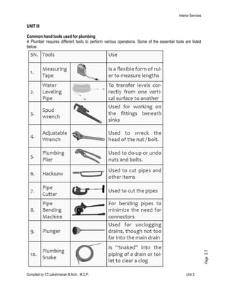
  • 1. Interior Services Compiled by CT.Lakshmanan B.Arch., M.C.P. Unit 3 Page3.1 UNIT III Common hand tools used for plumbing A Plumber requires different tools to perform various operations. Some of the essential tools are listed below.
  • 2. Interior Services Compiled by CT.Lakshmanan B.Arch., M.C.P. Unit 3 Page3.2 PIPES AND THEIR JOINTS: Pipes are manufactured by using different types of materials like steel, cast iron, galvanized iron, brass, copper, aluminum, lead, plastic, concrete, asbestos, etc. They are usually classified according to the material. They are also grouped as cast, welded, seamless, extruded, etc. For conveying large quantity of water, cast iron, steel or concrete pipes having large diameter are usually used. Galvanized iron pipes (GI pipes) are popular for medium and low pressure water supply lines. Plastic pipes are preferred for household uses at low pressure. Pipes are generally specified by their inner diameter (Nominal diameter specified in inches). Hence, the pipe fitting size is also based on this dimension. But for plastic pipes, this rule is not strictly followed because threading is not usually required for them. For engineering uses, along with the nominal diameter, the pipe thickness is also specified as light, medium or heavy. Types of pipe joints: According to the pipe material, size and application, different methods are used to join pipes. The most common types of pipe joints are: 1. Screwed pipe joint – For GI Pipes 2. Welded pipe joint – for steel, copper, aluminum and lead pipes 3. Flanged pipe joint – for cast iron and steel pipes 4. Soldered pipe joint – for brass and copper tubes 5. Glued or cemented pipe joint – for PVC pipes Pipes made of iron (GI Pipes) and brass of small and medium diameters (10 mm to 100 mm) are usually joined by screwing the pipe specials with internal or external threads. Welding is used to make permanent joint of medium and large diameter steel pipes. Flanged pipe joints are common in medium and large diameter pipes of cast iron and steel, along with rubber/CAF (Compressed asbestos fibre) gaskets. The flanged are screwed to the pipe for smaller diameter but made integral for large diameters. Pipes of copper and brass are usually joined by soldering. PVC (poly Vinyl Chloride) pipe is the most popular choice in plastic group. It is rigid and uses thread and solvent weld (glue) connections. It also can be heat fused. PVC pipes are available in various pressure ratings for water supply, and is a very choice for landscape irrigation. The reasons for the popularity are the economy, no corrosion and easiness to work. CPVC is a different type of plastic, which has an extra chlorine atom in the compound, can be used for the hot water supply, and in industry. To join plastic pipes, gluing or cementing method is used. Solvent cement is the gluing material and it partially melts the surface of the plastic pipe to make the joint. As the glue evaporates within two minutes, a strong joint is obtained. Screwed pipe fittings, (pipe specials) are removable or temporary pipe connections which permit necessary dismantling or reassembly for the purpose of installation, maintenance, cleaning, repair, etc. The functions of pipe fittings can be broadly classified as: 1. To join two or more pipe lines together 2. To effect change in diameter or direction 3. To close the end of a pipe line
  • 3. Interior Services Compiled by CT.Lakshmanan B.Arch., M.C.P. Unit 3 Page3.3 The most common types of screwed pipe fittings used in galvanized iron (GI) pipe lines and plastic (PVC) pipe lines are shown in Figure 1 (I to 17). A brief description of these fittings is given below 1. Coupler (coupling): Two pipe lines of equal diameter and in axial alignment can be joined by a coupler (coupling). It is a short sleeve with internal thread. 2. Reducer coupler (Reducer coupling): This is a coupler to join two pipe lines of different diameters in axial alignment. 3. 900 Elbow: This is a pipe special used or effecting abrupt change in direction through 90°. Internal threads are provided on both ends. An elbow brings twice the head loss than a bend. 4. 900 Reducer elbow: This is an elbow with outlet diameter less than that of inlet diameter It is used to join two pipe lines having different diameters and meeting at right angle. 5.Bend: This is a pipe special used to effect gradual change in direction (usually 90°).The two ends of the bend are externally threaded. 6. Return bend: This bend is used to return the direction of pipe line through 180°.The ends are internally threaded for fitting the pipe lines. 7. Tee: This pipe special is used to make a branch connection of same diameter to the main pipe line at right angle. A Tee is internally threaded and it connects three ends of pipes. 8. Reducer Tee: This is a pipe special similar to Tee used to take a branch connection of reduced diameter from the main pipe line. 9, Cross: This pipe special is used to take two branch connections at right angles to the main pipe line. The threads are provided internally, 10. Close nipple: A nipple is a short straight piece of pipe with external thread on both ends. A close nipple is the shortest one of this category with external thread for the full length. They are used to join two internally threaded pipe specials and valves. 11. Short nipple: A short nipple has the same shape and function of a close nipple, but it has a short unthreaded portion at the middle of its length for gripping. 12. Short nipple with hexagonal grip: This nipple has an additional hexagonal nut shape at the middle portion for easy screwing with spanner. It is similar to an ordinary short nipple, except that difference. 13. Hose nipple: A hose nipple is used to connect a hose (flexible pipe-usually plastic or rubber) to a pipe line. One end of the hose-nipple has a stepped taper to fit the hose, while other end has thread. A hexagonal nut shape is given to the middle portion for gripping with a spanner. 14. Male plug: A male plug is used to close an internally threaded end of a pipe line or pipe special. It has external thread and a grip of square shape at the end.
  • 4. Interior Services Compiled by CT.Lakshmanan B.Arch., M.C.P. Unit 3 Page3.4 15. Female plug (cap): A female plug is used to close an externally thread end of a pipe or pipe special. It has internal thread and a grip of square shape at the end. 16. Screwed union: II consists of three pieces as shown in the drawing. The two end pieces have internal threads at their ends which are connected to the pipe ends. The central hexagonal (or octagonal) piece (union nut) has internal thread at one end and a collar at the other end. After the end pieces are screwed on to the pipes, the central piece (union nut) is tightened to draw the end pieces together to get a water tight joint. 17. Flange: This is a disc type pipe special having threaded hole at the centre for screwing to the externally threaded end of a pipe line. It will have holes around the central hole at equal angular spacing (3, 4, 6f or 8 Nos.) for joining to another similar flange or flat surface using bolt or stud.
  • 5. Interior Services Compiled by CT.Lakshmanan B.Arch., M.C.P. Unit 3 Page3.5 Types of pipe fittings: Depending on the purposes served, pipe fittings can be categorized as under:  Pipe fittings to extend or terminate pipe runs: For example, Couplings, Adapters, Unions , Caps and Plugs Pipe.  Fittings to change a pipe's direction: For example , Elbows  Pipe fittings to connect two or more pipes: For example: Tees, Cross, Side-inlet Elbows, Wyes  Pipe fittings to change pipe size: For example, Reducers, Bushings, Couplings  Pipe fittings to manage or regulate flow: For example, Valves  Pipe fitting tools: For example, Pipe fasteners  Pipe flanges Various types of pipe fittings available in the market. Adapter : Adapters are an extremely important pipe fitting that extend or terminate pipe runs. They are used to connect dissimilar pipes. These fittings are somewhat similar to pipe couplings, with the difference that they connect pipe of different types
  • 6. Interior Services Compiled by CT.Lakshmanan B.Arch., M.C.P. Unit 3 Page3.6 Bulkhead fittings are specially designed fittings meant to allow free flow of liquids in tank, drum, drainage and other plumbing connections. These fittings are also used as distribution outlets in a piping system. Bulkhead fittings provide full flow of water and they are also used to attach flexible pipes with the help of male adapters. Compression fittings are special type of coupling, usually used to connect two pipes or a pipe to a fixture or valve. A compression fitting tightens down a sleeve or ferrule over a joint to prevent leakage. These pipe fittings are very strong and reliable and can be put on using just a pair of wrenches. These fittings do not require any heating and go well even with wet pipes. Pipe caps act as protective device and are designed to protect pipe ends of various shapes. The main purpose of using pipe caps is to waterproof the connections. They are also used to close the ends of hydraulic or pneumatic pipes and tubes. Pipe couplings are highly demanded in the pipe fitting market. Pipe couplings are fittings that help to extend or terminate pipe runs. These fittings are also used to change pipe size. Couplings extend a run by joining two lengths of pipe. They are known as reduced coupling if they are used to connect pipes of different sizes. Pipe elbow fittings is a very important pipe fitting. When we talk about a pipe elbow, it means a length of pipe with a sharp bend in it. Pipe elbows are fitting accessories which are used widely in various industrial sectors in pipe fitting. A pipe elbow is frequently used in pressurized applications and are available in various shapes and sizes for use in different applications. A pipe elbow is a fitting installed between two lengths of pipe or tube allowing a change of direction, usually in the 90° or 45° direction. A pipe ferrule is a type of pipe fitting made of various materials used especially for joining or binding one part to another (as pipe sections). A pipe ferrule consists of a circular clamp which is used to hold together and attach fibers, wires or posts. It is a type of a ring or cap attached to an object to protect against damage, splitting or wear. A pipe ferrule is also known as a circular fitting device that is used to hold the pipes together. A pipe nipple is a length of straight pipe with male threads on both ends. It is one of the most popular category of pipe fittings. It is a connector or a coupling threaded on both ends. Pipe nipples are used to allow plumbing to be connected to a water heater or other plumbing. They are used to fit straight end hose or pipe. Pipe plugs are defined as cap end of fractional tubes used in a large number of industries. These pipe plugs are designed to insert into the end of tubing to dead-end the flow. Various materials are used to manufacture high quality tube plugs in a variety of end connections. Pipe reducers are tube fittings that are widely used in a number of industries in order to providing greatest connection flexibility in connecting fractional tubes in various installations. Pipe reducer is a kind of pipe fitting that joins two pipes of different diameter. The pipe reducers are available in a range of materials depending on the end use of the products and these fittings are manufactured in inch and metric size. Pipe Union is a type of fitting equipment designed in such a way to unite two pipes which can be detached without causing any deformation to the pipes. Any kind of small diameter piping connections requiring a
  • 7. Interior Services Compiled by CT.Lakshmanan B.Arch., M.C.P. Unit 3 Page3.7 positive seal and easy assembly as well as disassembly are made with the help of pipe union. In other words, the pipe unions can disjoint two pipes very easily. They are widely demanded in the pipe fitting market. Pipe Tee is a type of pipe fitting which is T-shaped having two outlets, at 90° to the connection to the main line. It is a short piece of pipe with a lateral outlet. Pipe Tee is used to connect pipelines with a pipe at a right angle with the line. Pipe Tees are widely used as pipe fittings. They are made of various materials and available in various sizes and finishes. Pipe wyes: Pipe wyes are similar to pipe tees. The only difference is in that the branch line is angled to reduce friction which could hamper the flow. The pipe connection is typically at a 45-degree angle rather than a usual 90- degree angle. If a branch turns out at the end to be perpendicular to the through line, the pipe fitting becomes a "tee wye". Pipe sleeve is a popular kind of pipe fitting used in various industrial applications. It is available in various sizes, materials depending on the applications in which they are applied. Sleeves are used for variety of purposes and hence widely demanded in the pipe fitting market. Pipe sleeves are user friendly to all users and specifiers like architects, mechanical and electrical engineers, network installers, designers, consultants, builders and plumbers everywhere. Pipe valves are mechanisms or devices to regulate or control the flow of liquid or gas within a pipe. While some valves are used to regulate the rate of flow, there are others that are used to stop it completely in order to prevent flooding or allow repairs to be made. There are varieties of pipe valves in various materials, sizes and finish , and each type of valve performs a specific task. Pipe valves are known by various names like faucets, stops, bibs, taps, cocks or even drains. They can be easily custom-made for specific applications. A pipe fastener is a device that mechanically joins or affixes two or more pipes together. Pipe fasteners cover both high tensile and mild steel bolts, clamps, nuts, screws, washers, studs, pins etc Pipe Flanges are widely used as a popular category of pipe fittings. A flange is used to mechanically connect two pipes together. It can also be used to mechanically connect a pipe to a tee, valve, choke or any other piece of equipment. Flanges are available in round, square, and rectangular shapes. Pipe Adapters Bulkhead Fittings Compression Fittings
  • 8. Interior Services Compiled by CT.Lakshmanan B.Arch., M.C.P. Unit 3 Page3.8 Pipe Cap Pipe Ferrule Pipe Reducer Pipe Wyes Pipe Fasteners Pipe Coupling Pipe Nipples Pipe Union Pipe Sleeve Pipe Flanges Pipe Elbow Pipe Plug Pipe Tee Pipe Valves
  • 9. Interior Services Compiled by CT.Lakshmanan B.Arch., M.C.P. Unit 3 Page3.9
  • 10. Interior Services Compiled by CT.Lakshmanan B.Arch., M.C.P. Unit 3 Page3.10
  • 11. Interior Services Compiled by CT.Lakshmanan B.Arch., M.C.P. Unit 3 Page3.11
  • 12. Interior Services Compiled by CT.Lakshmanan B.Arch., M.C.P. Unit 3 Page3.12
  • 13. Interior Services Compiled by CT.Lakshmanan B.Arch., M.C.P. Unit 3 Page3.13
  • 14. Interior Services Compiled by CT.Lakshmanan B.Arch., M.C.P. Unit 3 Page3.14
  • 15. Interior services Compiled by CT.Lakshmanan B.Arch., M.C.P. Unit 3 Page3.15
  • 16. Interior services Compiled by CT.Lakshmanan B.Arch., M.C.P. Unit 3 Page3.16 PLUMBING PIPES Plumbing pipes are like the veins of homes. As veins carry blood to the different organs of our body, plumbing pipes carry water to the different parts of home. They are also used to remove wastes in the form of sewage and allow venting of sewage gases to the outdoors. Plumbing pipe is a very important type of plumbing hardware. It is a tube or hollow cylinder used for the conveyance of fluid. It is made of various materials, of which metal and plastic are the most important ones. In metallic pipes, copper and galvanized pipes are popularly used while plastic pipes are preferred due to its light weight, non- corrosive properties, chemical resistance, and ease of making connections. Plumbing pipes are usually specified by their internal diameter but can also be specified by any combination of dimensions OD, ID and wall thickness, depending upon the choice of designer. Pipe: • Circular conduit where fluid flows under pressure • Designed to carry external and internal loads Requirement of good pipe: 1. Withstand external, internal and temperature stresses 2. Smooth for minimum frictional losses 3. Durable 4. Light 5. Noncorrosive 6. Cheap 7. Easy joint Pipe types as per materials: 1. Cast Iron Pipes 2. Wrought Iron Pipes 3. Steel Pipes 4. Galvanized Iron Pipes 5. Concrete Pipes 6. Plastic Pipes 7. Asbestos Cement Pipes 8. Wooden Pipes 9. Vitrified Clay Pipes 10. Lead and copper Pipes (a) Cast Iron (CI) Pipe: • Manufactured by sand molding or centrifugal method • Standard 1.8 m length but up to 3m for smaller diameter • 50 mm to 1.2 m dia. Advantages: Easy to join, can withstand high pressure, resistance to corrosion, long life (> 100 yrs), durable, strong and moderate in cost, joined by flanged or Spigot and socket joint, low maintenance cost . Disadvantages: Brittle and very heavy so difficult to transport and may be expensive. Suitability: Suitable for distribution system (b) Wrought Iron (WI) Pipe: • Manufactured by rolling the flat plates of metal to proper diameter and welding to the edges Advantages: Strong, light weight, can withstand high pressure (400 m) and cheaper than CI pipes Disadvantages: It can’t withstand external load and when there is no water inside, liable to corrosion and costly to maintain. It is costlier than CI pipes Suitability: Occasionally used for main lines where pressure is high (c) Steel Pipe: • Manufactured by WI or mild steel which are galvanized by providing a protective coating of zinc on inner and outer surface
  • 17. Interior services Compiled by CT.Lakshmanan B.Arch., M.C.P. Unit 3 Page3.17 Advantages: It is cheap, light, easy in handling and transport, easy in joining with screwed socket joints and 20 years of life, resistant to corrosion when exposed to atmosphere Disadvantages: may get corroded by acidic and alkaline waters and liable to incrustation. Suitability: main lines where pressure is high and when pipe is exposure in open atmosphere (d) Galvanized iron (GI) pipes: • Manufactured similar as WI pipes • 15,20,25,32,40,50,63,75,90,110,125,150, 200 mm inner dia Advantages: Light in weight, easy in transport, handling, cutting, threading, working, joining, and gives neat appearance, joined couplings or screwed socket joint. Disadvantages: Costly, corrosive and less durable than CI pipes Suitability: Inside plumbing in buildings but not used nowadays due to high cost. (e) Concrete pipes: • Made of cement concrete (precast or cast in site) Advantages: Withstand 150 m head of water, resist corrosion and life is above 75 years, maintenance cost is low, least thermal expansion, can be laid under water and resist normal traffic load Disadvantages: Precast type is heavy to handle and transport, concrete pipes can’t resist high pressure and difficult to repair, it may be affected by acids and alkali and salty waters, difficult to join and liable to leak due to porosity Suitability: Where water does not flow under pressure (i.e. sewerage system) (f) Plastic Pipes: Made of Plastic and common in nowadays it is corrosion resistant, light in weight and economical Advantages: Light, cheap, available in longer length, electrical insulation, corrosion free, life correspond to GI Disadvantages: Less resistant to hot water, may impart smell to water, can be easily cut. Suitability: All water supply systems Types: 1. Low density polyethylene (LDPE) pipes: Used in electrical wiring 2. High density polyethylene (HDPE)pipes 3. Polyvinyl chloride (PVC) pipes: 4. Unplastisized Polyvinyl chloride (UPVC) pipes: 5. Poly Propylene Random (PPR) Pipes: (g) Asbestos cement (AC) pipes: • Made of mixture of cement and asbestos fibers Advantages: not affected by salt water and corrosive materials, smooth, light so easy in handling Disadvantages: Affected by alkali and acid and also brittle so costlier in transport. Suitability: Small size distribution pipes (h) Wooden pipes: • made of wood by making channels or boring at center and used in ancient times • not used in water supply nowadays
  • 18. Interior services Compiled by CT.Lakshmanan B.Arch., M.C.P. Unit 3 Page3.18 (i) Copper and Lead Pipes: • Copper pipe is made of copper and can resist corrosion even if water contains some acids and expensive so not used in water supply nowadays • Leads are soluble in water so lead pipe causes lead poisoning hence it is not used in water supply nowadays. (j) Vitrified clay Pipes: • made of vitrified clay so has smooth surface • not used in water supply nowadays TYPES OF VALVES USED IN WATER SUPPLY PIPE LINES Valves in pipe lines are provided to control supply of water. They are used to stop supply when any repair is carried in pipe line. There are fourteen types of valves for plumbing.  Stop Valve This valve is suitable means of connections for inserting and controlling the flow of water. Nominal size of valve is designated by nominal bore of the pipe to which the valve is normally fitted. The body and bonnet of this valve is made from cast brass. In large buildings sufficient numbers of stop valves are fixed on branch pipes to minimize interruption of supply during repairs. A stop valve is also called stopcock. There are two types of stop valves. 1). Internally threaded 2). Externally threaded  Fancy Stop Valve These valves are available in normal sizes of 15 mm and 20 mm. These are also called open stopcock valves.
  • 19. Interior services Compiled by CT.Lakshmanan B.Arch., M.C.P. Unit 3 Page3.19  Angle Stop Valve This valve has inlet and outlet at right angles to each other. This is used to stop supply of water to geyser, flushing cistern and wash basin etc. This valve is also used for servicing of water fitting to be carried out without shut off complete water supply of the house.  Concealed Stop Valve It is used to regulate supply of hot and cold water to shower, mixer etc. in concealed plumbing line.  Gate Valve Gate valve is full way valve which is inserted into a pipeline for controlling or stopping the flow of water. This valve offers low resistance to the flow of water. The valve is closed by turning hand wheel into clock wise direction. Nominal sizes of valves are 15 mm to 100 mm.  Ball Valve Ball valve is an automatic flow control device. Regulating principle is the level of some free water surface.
  • 20. Interior services Compiled by CT.Lakshmanan B.Arch., M.C.P. Unit 3 Page3.20  Foot Valve This valve is placed at the bottom of suction pipe of pump. This valve lets the water to enter suction pipe when it is opened and prevents the water from flowing back when it is closed.  Air Relief Valve This valve is an integral part of a pool of pumping and filtration system. When the pump of pool pumps out water from the pool, the water is forced through a filter. Then the water is forced through air-relief valve.  Pressure Relief Valve
  • 21. Interior services Compiled by CT.Lakshmanan B.Arch., M.C.P. Unit 3 Page3.21 This valve protects pipe from sudden increase in pressure. It is a device attached with a boiler or other vessel for relieving the pressure of steam automatically before it becomes enough to cause burst.  Scour Valve or Washout Valve This valve is used at valley point of a pipe line to clean pipe line.  Sluice Valve or Globe Valve These valves are used to control the flow and for frequent operation. These are normally used in CI main line.  Butterfly Valve This valve contains a circular disc which rotates in the direction of flow in pipe. It is a type of flow control device that is used to regulate flow of fluid through a section of pipe. This valve is similar to ball valve in operation. A flat circular plate is fixed in the center of pipe.
  • 22. Interior services Compiled by CT.Lakshmanan B.Arch., M.C.P. Unit 3 Page3.22  Float Valve or Ball Cock This valve is used in water tanks and cisterns to maintain constant water level and to prevent overflow. It is activated by means of a lever and float (ball). The rise and fall of ball controls the flow of water. This valve is generally made for high, medium and low pressure.  Bib cock/bib tap A Bib cock/Bib tap is fitted horizontally to the pipe as in kitchen, bath etc. This valve is used to obtain water from direct water supply or from storage tank.
  • 23. Interior services Compiled by CT.Lakshmanan B.Arch., M.C.P. Unit 3 Page3.23 Choice of Materials for Pipes and Fittings The following material may be used for a sanitary pipework system: a. Asbestos cement b. Cast iron c. Salt glazed stoneware pipes d. Galvanized steel and wrought iron and e. Any other material as approved by the local authority. MINIMUM INTERNAL DIAMETERS FOR WASTE APPLIANCES ITEM DIAMETER mm Drinking fountains 25 Wash basins 30 Bidets 30 Domestic sinks and baths 40 Shower bath trays 40 Domestic bath tubs 50 Hotel and canteen sinks 50 Urinals: Stall urinals (with not more than 1-20 m of channel drainage) 50 Lip urinals 40 Floor traps (outlet diameter) 65 Selection of Traps for Various Purposes—The factors given in Tables 1 and 2 should receive consideration in relation to attached traps. TABLE 1 FIXTURE UNITS FOR DIFFERENT SANITARY APPLIANCE OR GROUP Type of Fixture Fixture Unit Value as Load Factors One bath room group consisting of water closet, wash basin and bath tub or shower stall: a) Tank water closet 6 b) Flush-valve water closet 8 Bath tub* 3 Bidet 3 Combination sink-and-tray (drain board) 3 Drinking fountain ½ Floor traps‡ 1 Kitchen sink, domestic 2 Wash basin, ordinary‡ 1 Wash basin, surgeon’s 2 Shower stall, domestic 2 Showers (group) per head 3 Urinal wall lip 4 Urinal stall 4 Water closet, tank-operated 4 Water closet, valve-operated 8 *A shower head over a bath tub does not increase the fixture value. †Size of floor trap shall be determined by the area of surface water to be drained. ‡Wash basins with 32 mm and 40 mm trap have the same load value.
  • 24. Interior services Compiled by CT.Lakshmanan B.Arch., M.C.P. Unit 3 Page3.24 TABLE 2 FIXTURE UNIT VALUES FOR FIXTURES BASED ON FIXTURE DRAIN OR TRAP SIZE FIXTURE DRAIN OR TRAP ŜIZE (mm) FIXTURE UNIT VALUE 30 and smaller 1 40 2 50 3 65 4 75 5 100 6 TABLE 3 MAXIMUM NUMBER OF FIXTURE UNITS THAT CAN BE CONNECTED TO BRANCHES AND STACKS Diameter of Pipe mm Maximum Number of Fixture Units* That may be Connected to Any Horizontal Fixture Branch† One Stack of 3 Storeys in Height or 3 Intervals More Than 3 Storeys in Height Total for stack Total at one storey on branch interval (1) (2) (3) (4) (5) 30 1 2 2 1 40 3 4 8 2 50 6 10 24 6 65 12 20 42 9 75 20 30 60 16 100 160 240 500 90 125 360 540 1 100 200 150 620 960 1 900 350 200 1 400 2 200 3 600 600 250 2 500 3 800 5 600 1 000 300 3 900 6 000 8 400 1 500 375 7 000 — — — *Depending upon the probability of simultaneous use of appliances considering the frequency of use and peak discharge rate. †Does not include branches of the building sewer. TABLE 4 MAXIMUM NUMBER OF FIXTURE UNITS THAT CAN BE CONNECTED TO BUILDING DRAINS AND SEWERS Diameter of Pipe mm GRADIENT 1/200 1/100 1/50 1/25 100 — 180 216 250 150 — 700 840 1 000 200 1 400 1 600 1 920 2 300 250 2 500 2900 3500 4200 300 3900 4600 5600 6 700 375 7000 8300 10 000 12 000
  • 25. Interior services Compiled by CT.Lakshmanan B.Arch., M.C.P. Unit 3 Page3.25 TABLE 4 MAXIMUM NUMBER OF FIXTURE UNITS THAT CAN BE CONNECTED TO BUILDING DRAINS AND SEWERS Diameter of Pipe mm GRADIENT 1/200 1/100 1/50 1/25 Note 1—Maximum number of fixture units that may be connected to any portion (see Note 2) of the building drain or the building sewer is given. Note 2—Includes branches of the building sewer. Gradients and Pipe Sizes Gradients The discharge of water through a domestic drain is intermittent and limited in quantity and, therefore, small accumulations of solid matter are liable to form in the drains between the building and the public sewer. There is usually a gradual shifting of these deposits as discharges take place. Gradients shall be sufficient to prevent these temporary building up and blocking the drains. Normally, the sewer shall be designed for discharging three times the dry-weather flow flowing half-full with a minimum self-cleansing velocity of 0·75 m/s. The approximate gradients which give this velocity for the sizes of pipes likely to be used in building drainage and the corresponding discharges when flowing half-full are as follows: Diameter Gradients Discharge mm m3 /min 100 1 in 57 0·18 150 1 in 100 0·42 200 1 in 145 0·73 230 1 in 175 0·93 250 1 in 195 1·10 300 1 in 250 1·70 In cases, where it is practically not possible to conform to the ruling gradients, a flatter gradient may be used but the minimum velocity in such cases shall on no account be less than 0·61 m/s. Note—Where gradients are restricted, the practice of using pipes of larger diameter than is required by the normal flow in order to justify laying at a flatter gradient does not result in increasing the velocity of flow but reduces the depth of flow and for this reason is to be deprecated. On the other hand, it is undesirable to employ gradients giving a velocity of flow greater than 2·4 m/s. Where it is unavoidable, cast-iron pipes shall be used. The approximate gradients which give a velocity of 2·4 m/s for the various sizes of pipes and the corresponding discharge when flowing half-full are as follows:
  • 26. Interior services Compiled by CT.Lakshmanan B.Arch., M.C.P. Unit 3 Page3.26 Diameter Gradient Discharge mm m3 /min 100 1 in 5·6 0·59 150 1 in 9·7 1·32 200 1 in 14 2·4 230 1 in 17 2·98 250 1 in 19 3·60 300 1 in 24·5 5·30 TABLE 5 SIZING OF RAIN-WATER PIPES FOR ROOF DRAINAGE Sl No. Dia or Pipe mm Average Rate of Rainfall in mm/h 50 75 100 125 150 200 Roof Area, Square Metres i) 50 13·4 8·9 6·6 5·3 4·4 3·3 ii) 65 24·1 16·0 12·0 9·6 8·0 6·0 iii) 75 40’8 27·0 20·4 16·3 13·6 10·2 iv) 100 85·4 57·0 42·7 34·2 28·5 21·3 v) 125 — — 80·5 64·3 53·5 40·0 vi) 150 — — — — 83·6 62·7 TEST FOR PIPES 1. Smoke Test All soil pipes, waste pipes, and vent pipes and all other pipes when above ground shall be approved gas-tight by a smoke test conducted under a pressure of 25 mm of water and maintained for 15 minutes after all trap seals have been filled with water. The smoke is produced by burning oily waste or tar paper or similar material in the combustion chamber of a smoke machine. Chemical smokes are not satisfactory. 2. Water Test a. For pipes other than cast iron—Glazed/stoneware and concrete pipes shall be subjected to a test pressure of at least 1.5 m head of water at the highest point of the section under test. The tolerance figure of two litres per centimetre of diameter per kilometre may be allowed during a period of ten minutes. The test shall be carried out by suitably plugging the low end of drain and the ends of connections, if any, and filling the system with water. A kuncklebend shall temporarily be jointed in at the top end and a sufficient length of the vertical pipe jointed to it so as to provide the required test head or the top end may be plugged with a connection to a hose ending in a funnel which could be raised or lowered till the required head is obtained and fixed suitably for observation. Subsidence of the test water may be due to one or more of the following causes:
  • 27. Interior services Compiled by CT.Lakshmanan B.Arch., M.C.P. Unit 3 Page3.27 a. Absorption by pipes and joints, b. Sweating of pipes or joints, c. Leakage at joints or from defective pipes, and d. Trapped air. Allowance shall be made for (a) by adding water until absorption has ceased after which the test proper should commence. Any leakage will be visible and the defective part of the work should be cut out and made good. A slight amount of sweating which is uniform may be overlooked, but excessive sweating from a particular pipe or joint shall be watched for and taken as indicating a defect to be made good. Note—This test will not be applicable to sanitary pipe work aboveground level. b. For cast iron pipes—Cast iron sewers and drains shall be tested as for glazed stone ware and concrete pipes. The drain plugs shall be suitably strutted to prevent their being forced out of the pipe during the test. Tests for Straightness and Obstruction—The following tests shall be carried out: a. by inserting at the high end of the sewer or drain a smooth ball of a diameter 13 mm less than the pipe bore. In the absence of obstruction, such as yarn or mortar projecting through the joints, the ball should roll down the invert of the pipe and emerge at the lower end; and b. by means of a mirror at one end of the line and lamp at the other. If the pipeline is straight, the full circle of light may be observed. If the pipeline is not straight, this will be apparent. The mirror will also indicate obstruction in the barrel. Abbreviations Branch Soil Pipe (B.S.P.)— A pipe connecting one or more soil appliances to the main soil pipe. Branch Waste Pipe (B.W.P) — A pipe connecting one or more waste appliances to the main waste pipe. Main Soil Pipe (M.S.P.)— A pipe connecting one or more branch waste pipes to the drain. Main Waste Pipe (M.W.P.)— A pipe connecting one or more branch waste pipes to the drain. SOIL PIPE, WASTE PIPE AND VENTILATING PIPE Soil Pipe  A soil pipe conveying to a drain any solid or liquid filth shall be circular and shall have a minimum diameter of 100 mm.  Except where it is impracticable, the soil pipe shall be situated outside the building or in suitably designed pipe shafts and shall be continued upwards without diminution of its diameter, and (except where it is unavoidable) without any bend or angle, to such a height and position as to afford by means of its open end a safe outlet for foul air. Even if the pipes are laid in external chases, the soil pipes shall not be permitted on a wall abutting a street unless the Authority is satisfied that it is unavoidable. Where pipe shafts are provided the cross-sectional area shall be such as to allow free and unhampered access to the pipes to be installed in the shaft and in no case shall the cross section be less than a square of 1 metre side. All pipe shafts shall be provided with an access door at ground level and facilities for ventilation.  Soil pipes, whether inside or outside the building, shall not be connected with any rain water pipe and there shall not be any trap in such soil pipe or between it any drain with which it is connected.  Soil pipes shall preferably be of cast iron. Asbestos cement building pipes may also be used as soil pipes only above ground level.  The soil pipe shall be provided with heel rest bend which shall rest on sound footing. It shall be fixed at least 50 mm clear of the finished surface of the wall by means of suitable clamps of approved type.
  • 28. Interior services Compiled by CT.Lakshmanan B.Arch., M.C.P. Unit 3 Page3.28 Waste Pipe  Every pipe in a building for earring off the waste or overflow water from every bath, wash basin or sink to a drain shall be of 32 to 50 mm diameter, and shall be trapped immediately beneath such wash basin or sink by an efficient siphon trap with adequate means for inspection and cleaning. Such traps shall be ventilated into the external air whenever such ventilation is necessary to preserve the seal of the trap. Waste pipes, traps, etc, shall be constructed of iron, head, brass, stoneware, asbestos cement or other approved material. The overflow pipe from wash basins, sinks, etc, shall be connected with the waste pipe immediately above the trap. Vertical pipes carrying off waste water shall have a minimum diameter of 75 mm. Note—Wherever wash basins and sinks have in-built overflow arrangements, there is no need to provide overflow pipes in such cases.  Every pipe in a building for carrying off waste water to a drain shall be taken through an external wall of the building by the shortest practicable line, and shall discharge below the grating or surface box of the chamber but above the grating of a properly trapped gully. The waste pipe shall be continued upwards without any diminution in its diameter and (except when unavoidable) without any bend or angle to such a height and position as to afford by means of the open end of the waste pipe, a safe outlet for foul air, the position of the open end and its covering being such as to comply with the condition.  Except where it is impracticable, the common waste pipe shall be situated outside the building and shall be continued upwards without diminution of its diameter (except where it is unavoidable) without any bend or angle being formed to such a height and position as to afford by means of the open end a safe outlet for foul air, the position of the open end and the covering thereafter being such as to comply with the conditions set out in ventilated pipe.  The waste pipe shall be finally attached to the wall at least 5 cm clear of it, if the waste pipe is of cast iron, the pipe shall be secured to the walls properly fixed holderbats or equally suitable and efficient means. Ventilating Pipe  Ventilating pipes should be so installed that water cannot be retained in them. They should be fixed vertically. Whenever possible horizontal runs should be avoided. Ventilating pipe shall be carried to such a height and in such a position as to afford by means of the open end of such pipe or vent shaft, a safe outlet for foul air with the least possible nuisance.  The upper end of the main ventilating pipe may be continued to the open air above roof level as separate pipe, or it may join the MSP (Main Soil Pipe) and/or MWP(Main Waste Pipe) above the floor level of the highest appliance. Its lower end may be carried down to join the drain at a point where air relief may always be maintained. Four typical methods of jointing the main ventilating pipe at the lower end.  Branch ventilating pipes should be connected to the top of the BSP (Branch Soil Pipe) and BWP (Branch Waste Pipe) between 75 mm and 450 mm from the crown of the trap.  The ventilating pipe shall always be taken to a point 150 cm above the level of the eaves or flat roof or terrace parapet whichever is higher or the top of any window within a horizontal distance of 3 m. The least dimension shall be taken as a minimum and local conditions shall be taken into account. The upper end of every ventilating pipe shall be protected by means of a cowl. Sizes  The building drain ventilating pipe shall be of not less than 75 mm diameter. When, however, it is used as MSP (Main Soil Pipe) or MWP(Main Waste Pipe), the upper portion, which does not carry discharges, shall not be of lesser diameter than the remaining portion.
  • 29. Interior services Compiled by CT.Lakshmanan B.Arch., M.C.P. Unit 3 Page3.29  The diameter of the main ventilating pipe shall not be less than 50 mm.  A branch ventilating pipe on a waste pipe in both one and two-pipe systems shall be of not less than two-thirds the diameter of the branch waste ventilated subject to a minimum of 25 mm.  A branch ventilating pipe on a soil pipe in both one- and two-pipe systems shall be not less than 32 mm in diameter. CONSTRUCTION RELATING TO CONVEYANCE OF RAIN OR STORM WATER  Roof Gutters - Roof gutters, shall be of galvanized iron sheets not less than l.25 mm in thickness. The gutter shall be semicircular in section with a width at top about twice the diameter of the down pipe. The gutters shall be fixed 25 mm below the edge of the roof.  MS brackets 25 x 6 mm shall be used to support the gutter at about 1.2 m intervals. A convenient method will be to fix the brackets to every alternate after with three 50 mm screws.  All junctions and joints shall be thoroughly water-tight-riveted, bolted or soldered. All joints between successive length of gutters shall have an overlap of at least 50 mm. The drop in the overlap shall always be in the direction of the fall of the gutter. Ends of guttering shall be closed with galvanized sheets not less than 1.25 mm in thickness, to fit the section and made water-tight. Junctions with down-fall rain-water pipes or leaders shall be made water-tight. Gutters shall have a general minimum fall of 1 in 120. RAIN-WATER PIPES  Cast Iron Pipes - Rain-water pipes or leaders if of cast iron shall be with socketed joints having lugs cast on for fixing The shoe may be fixed 150 mm above ground level. Bends and offsets are to be avoided as far as possible.  Galvanized Iron Pipes - The work will be similar to cast iron pipes except that they are fixed with straps or dogs one for each 2m length of pipe. Joints between successive lengths of pipes will be by collars at least 10 cm deep riveted tightly and securely to the pipes, and the straps be riveted or bolted through this collar by 9.5 mm galvanized iron bolts.  Asbestos Cement Pipes - pipes will be fixed with straps or clips. All rain-water leaders from roofs or terraces shall be screened off by gratings at the top to prevent leaves, rodents, etc, entering the pipes