Downloaded 178 times

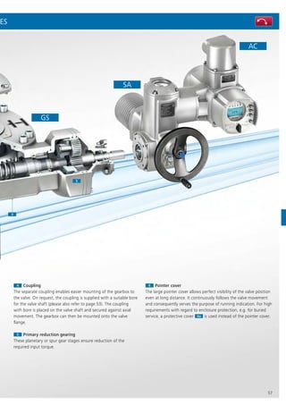
![66
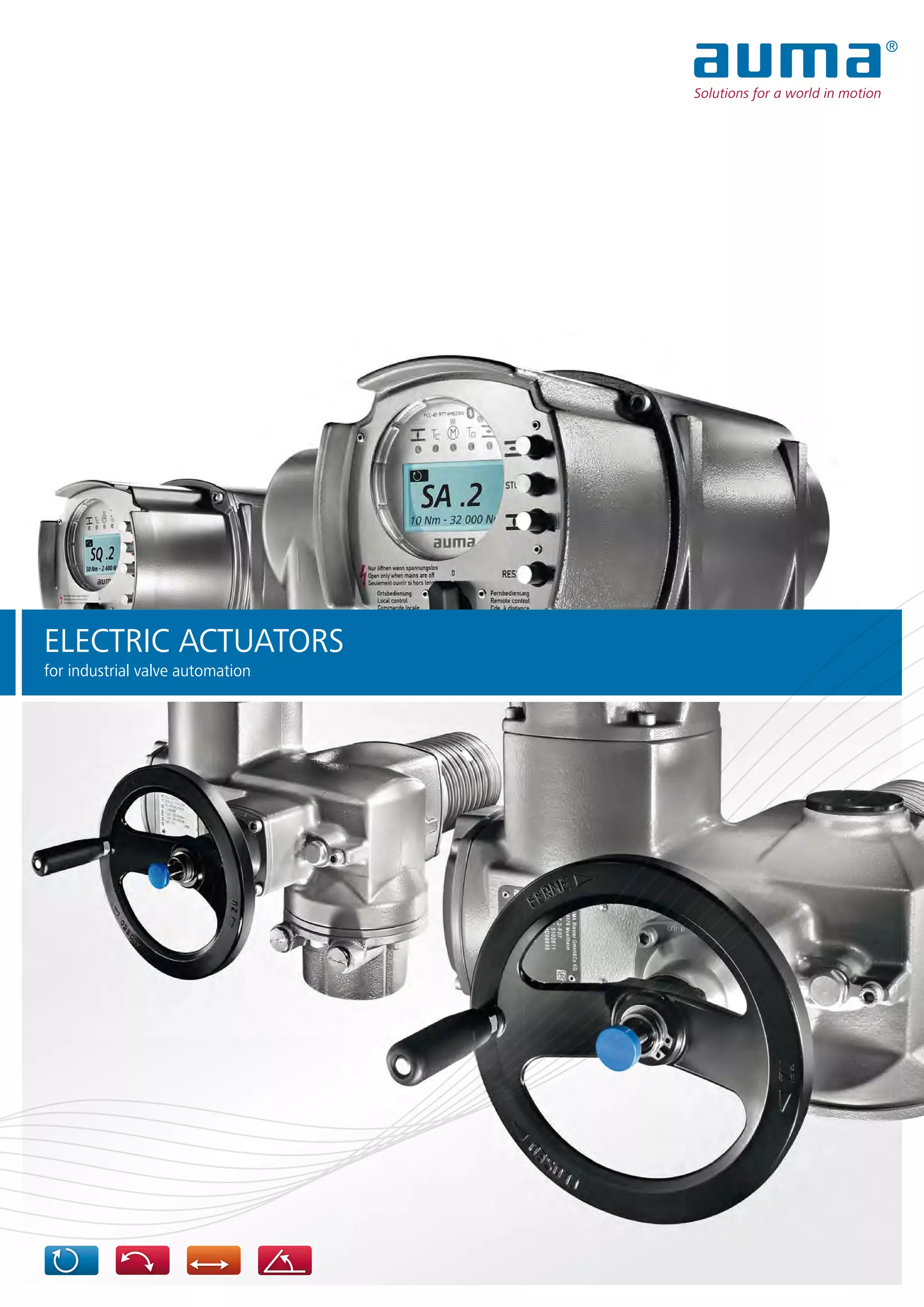
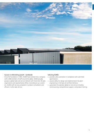
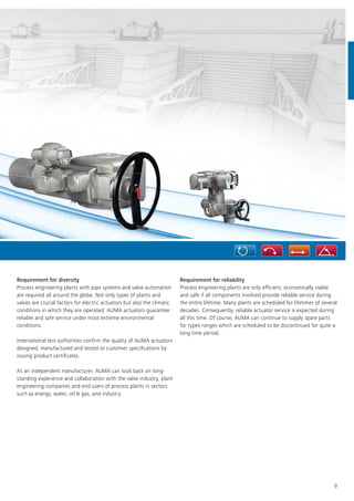
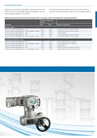
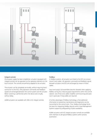
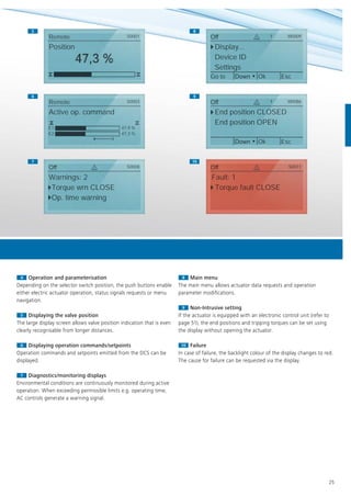
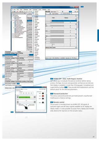
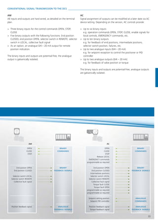
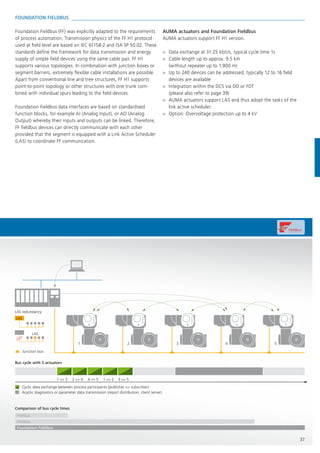
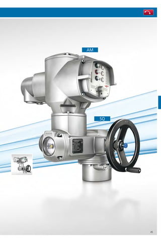
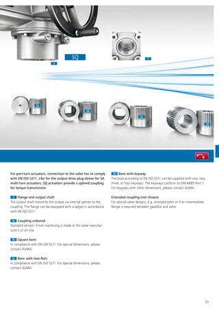
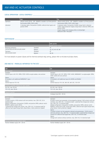
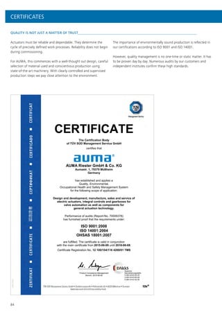
SA MULTI-TURN ACTUATORS FOR OPEN-CLOSE DUTY
The following data applies to actuators with 3-phase motors, operated in type of duty S2 - 15 min/classes A and B in compliance with
EN 15714-2. For further information on other motor types and types of duty, refer to separate technical and electrical data sheets.
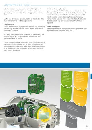
Type
Output
speeds at
50 Hz1
Setting range for tripping torque
Number of starts
Starts max. Valve mounting flange
[rpm] [Nm] [1/h] EN ISO 5210 DIN 3210
SA 07.2 4 – 180 10 – 30 60 F07 or F10 G0
SA 07.6 4 – 180 20 – 60 60 F07 or F10 G0
SA 10.2 4 – 180 40 – 120 60 F10 G0
SA 14.2 4 – 180 100 – 250 60 F14 G1/2
SA 14.6 4 – 180 200 – 500 60 F14 G1/2
SA 16.2 4 – 180 400 – 1,000 60 F16 G3
SA 25.1 4 – 90 630 – 2,000 40 F25 G4
SA 30.1 4 – 90 1,250 – 4,000 40 F30 G5
SA 35.1 4 – 45 2,500 – 8,000 30 F35 G6
SA 40.1 4 – 32 5,000 – 16,000 20 F40 G7
SA 48.1 4 – 16 10,000 – 32,000 20 F48 –
SA MULTI-TURN ACTUATORS AND SQ PART-TURN ACTUATORS
SAR MULTI-TURN ACTUATORS FOR MODULATING DUTY
The following data applies to actuators with 3-phase motors, operated in type of duty S4 - 25 %/class C in compliance with EN 15714-2.
For further information on other motor types and types of duty, please refer to separate technical and electrical data sheets.
Type
Output
speeds at
50 Hz1
Setting range for
tripping torque
Maximum torque
for modulating duty
Number of starts
Starts max.2
Valve mounting flange
[rpm] [Nm] [Nm] [1/h] EN ISO 5210 DIN 3210
SAR 07.2 4 – 90 15 – 30 15 1,500 F07 or F10 G0
SAR 07.6 4 – 90 30 – 60 30 1,500 F07 or F10 G0
SAR 10.2 4 – 90 60 – 120 60 1,500 F10 G0
SAR 14.2 4 – 90 120 – 250 120 1,200 F14 G1/2
SAR 14.6 4 – 90 250 – 500 200 1,200 F14 G1/2
SAR 16.2 4 – 90 500 – 1,000 400 900 F16 G3
SAR 25.1 4 – 11 1,000 – 2,000 800 300 F25 G4
SAR 30.1 4 – 11 2,000 – 4,000 1,600 300 F30 G5](https://image.slidesharecdn.com/auma-electric-actuators-for-industrial-valve-automation-160831193859/85/Electric-Actuators-for-Industrial-Valve-Automation-66-320.jpg)
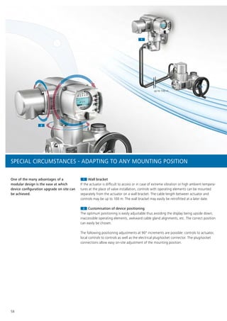
![67
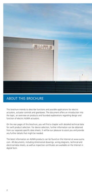
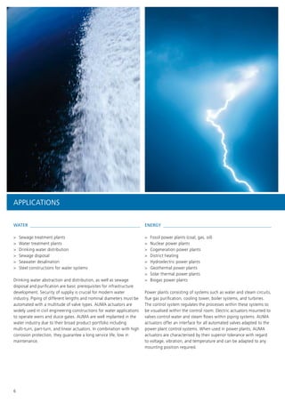
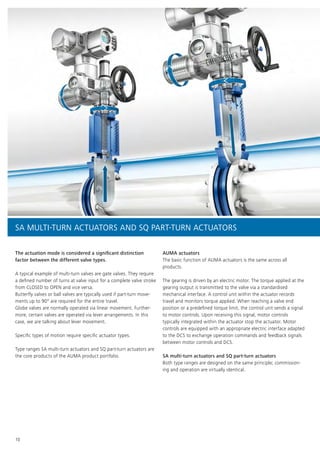
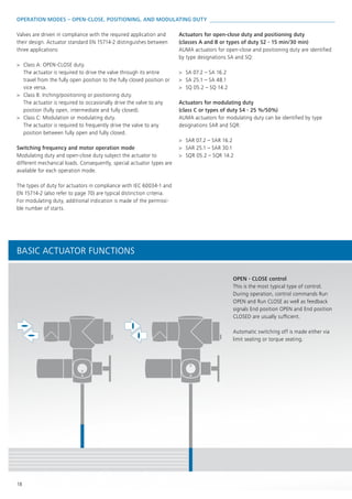
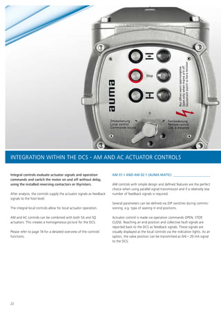
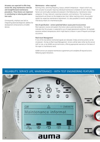
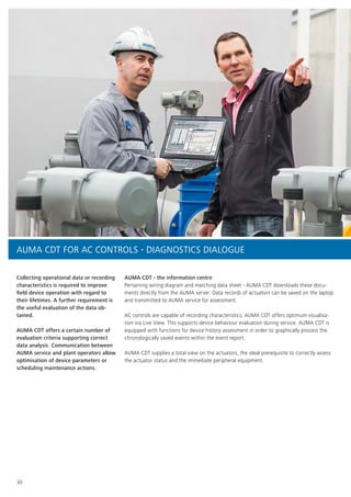
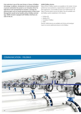
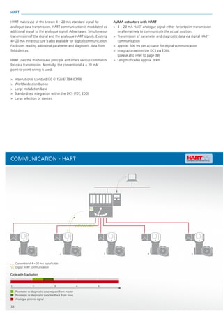
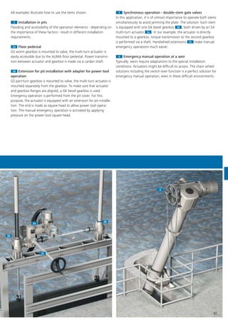
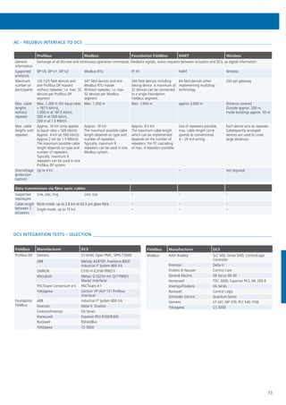
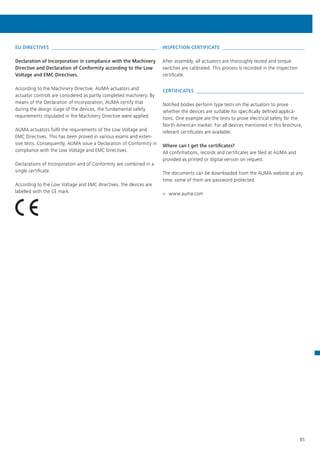
LIFETIME OF MULTI-TURN AND PART-TURN ACTUATORS
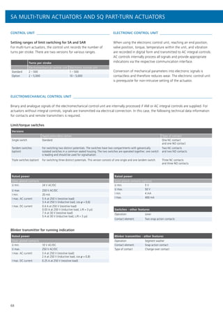
AUMA multi-turn and part-turn actuators of SA and SQ type ranges
exceed the lifetime demands of EN 15714-2. Detailed information
can be provided on request.
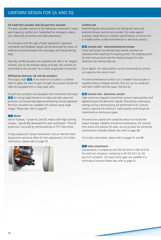
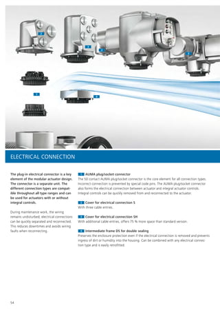
SQ PART-TURN ACTUATORS FOR OPEN-CLOSE DUTY
The following data applies to actuators with 3-phase motors, operated in type of duty S2 - 15 min/classes A and B in compliance with
EN 15714-2. For further information on other motor types and types of duty, please refer to separate technical and electrical data sheets.
Type
Operating
times at
50 Hz1
Setting range for tripping torque
Number of starts
Starts max. Valve mounting flange
[s] [Nm] [1/h] Standard (ISO 5211) Option (EN ISO 5211)
SQ 05.2 4 – 32 50 – 150 60 F05/F07 F07, F10
SQ 07.2 4 – 32 100 – 300 60 F05/F07 F07, F10
SQ 10.2 8 – 63 200 – 600 60 F10 F12
SQ 12.2 16 – 63 400 – 1,200 60 F12 F10, F14, F16
SQ 14.2 24 – 100 800 – 2,400 60 F14 F16
SWING ANGLE RANGES
Within the indicated swing angle ranges, the swing angle is freely
adjustable.
Swing angle range
Standard 75° – 105°
Option 15° – 45°; 45° – 75°; 105° – 135°; 135 ° – 165°;
165° – 195°; 195° – 225°
1
fixed output speeds or operating times applying factor 1.4
2
for the indicated higher output speeds, the maximum number of permissible starts
is low, refer to technical data sheets.
SQR PART-TURN ACTUATORS FOR MODULATING DUTY
The following data applies to actuators with 3-phase motors, operated in type of duty S4 - 25 %/class C in compliance with EN 15714-2.
For further information on other motor types and types of duty, please refer to separate technical and electrical data sheets.
Type
Operating
times at
50 Hz1
Setting range for
tripping torque
Maximum torque for
modulating duty
Number of starts
Starts max. Valve mounting flange
[s] [Nm] [Nm] [1/h] Standard (ISO 5211) Option (EN ISO 5211)
SQR 05.2 8 – 32 75 – 150 75 1,500 F05/F07 F07, F10
SQR 07.2 8 – 32 150 – 300 150 1,500 F05/F07 F07, F10
SQR 10.2 11 – 63 300 – 600 300 1,500 F10 F12
SQR 12.2 16 – 63 600 – 1 200 600 1,500 F12 F10, F14, F16
SQR 14.2 36 – 100 1,200 – 2,400 1,200 1,500 F14 F16](https://image.slidesharecdn.com/auma-electric-actuators-for-industrial-valve-automation-160831193859/85/Electric-Actuators-for-Industrial-Valve-Automation-67-320.jpg)
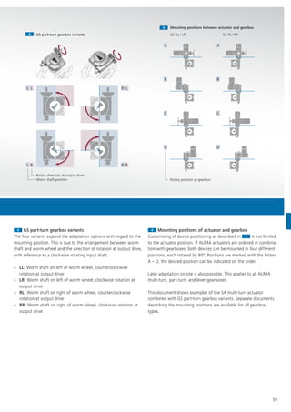
![70
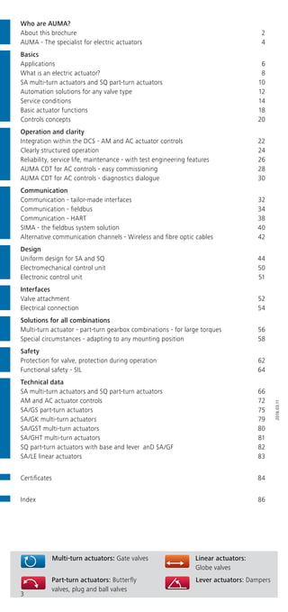
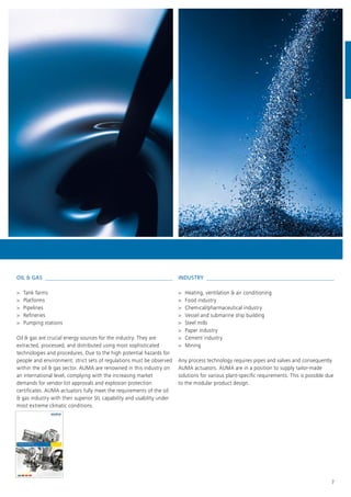
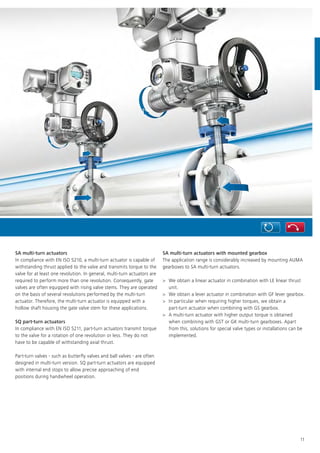
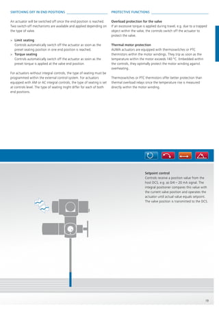
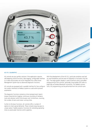
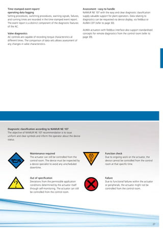
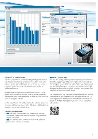
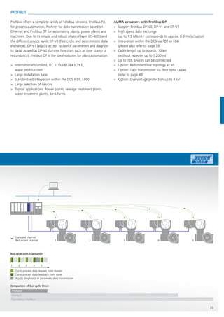
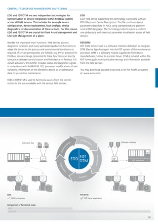
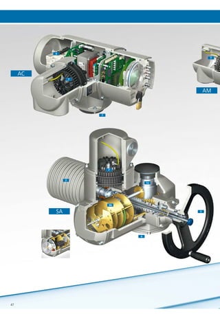
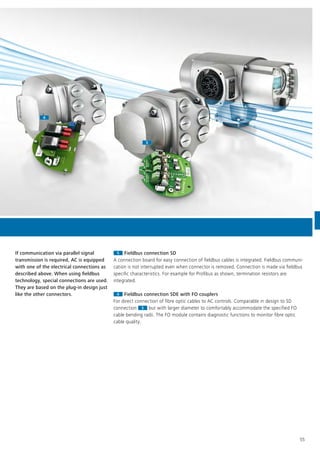
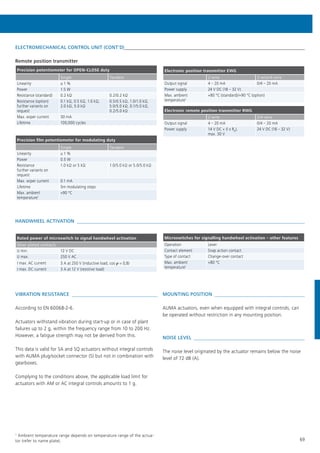
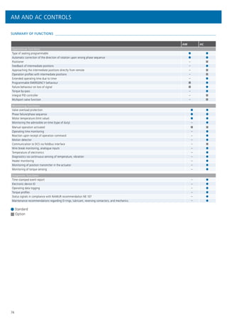
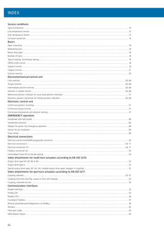
MOTOR
Rated values for motor protection
Thermoswitches are used as motor protection as standard. When
using integral controls, motor protection signals are internally
processed. This also applies for the optional PTC thermistors. For
actuators without integral controls, signals must be processed in
external controls.
Rating of the thermoswitches
1-phase AC voltage
(250 V AC) Switch rating Imax
cos j = 1 2.5 A
cos j = 0.6 1.6 A
DC voltage Switch rating Imax
60 V 1 A
42 V 1.2 A
24 V 1.5 A
Special motors
For special requirements, the actuators can be equipped with
special motors, e.g. brake motors or two-speed motors.
Type of duty according to IEC 60034-1/EN 15714-2
Type
3-phase AC
current
1-phase AC
current DC current
SA 07.2 – SA 16.2 S2 - 15 min,
S2 - 30 min/
classes A,B
S2 - 15 min1
/
classes A,B1
S2 - 15 min/
classes A,B
SA 25.1 – SA 48.1 S2 - 15 min,
S2 - 30 min/
classes A,B
– –
SAR 07.2 – SAR 16.2 S4 - 25 %,
S4 - 50 %/
class C
S4 - 25 %1
/
class C1
–
SAR 25.1 – SAR 30.1 S4 - 25 %,
S4 - 50 %/
class C
– –
SQ 05.2 – SQ 14.2 S2 - 15 min,
S2 - 30 min/
classes A,B
S2 - 10 min/
classes A,B1
–
SQR 05.2 – SQR 14.2 S4 - 25 %,
S4 - 50 %/
class C
S4 - 20 %/
class C1
–
Indications on type of duty refer to the following conditions:
Nominal voltage, 40 °C ambient temperature, average load of
approx. 35 % of maximum torque
Motor insulation classes
Insulation classes
3-phase AC motors F, H
1-phase AC motors F
DC motors F, H
SUPPLY VOLTAGES/MAINS FREQUENCIES
Hereafter, please find the standard supply voltages (other voltages
upon request). Some actuator versions or sizes are not available
with the stipulated motor types or voltages/frequencies. For
detailed information, please refer to the separate electrical data
sheets.
3-phase AC current
Voltages Frequency
[V] [Hz]
220; 230; 240; 380; 400; 415; 500; 525; 660; 690 50
440; 460; 480; 575; 600 60
1-phase AC current
Voltages Frequency
[V] [Hz]
230 50
115; 230 60
DC current
Voltages
[V]
24; 48; 60; 110; 220
Permissible fluctuations of mains voltage and frequency
>> Standard for SA, SQ, AM, and AC
Mains voltage: ±10 %
Frequency: ±5 %
>> Option for AC
Mains voltage: –30 %
Requires special sizing when selecting the actuator.
1
not available for all sizes
SA MULTI-TURN ACTUATORS AND SQ PART-TURN ACTUATORS](https://image.slidesharecdn.com/auma-electric-actuators-for-industrial-valve-automation-160831193859/85/Electric-Actuators-for-Industrial-Valve-Automation-70-320.jpg)
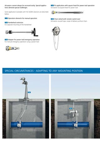
![76
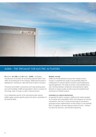
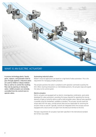
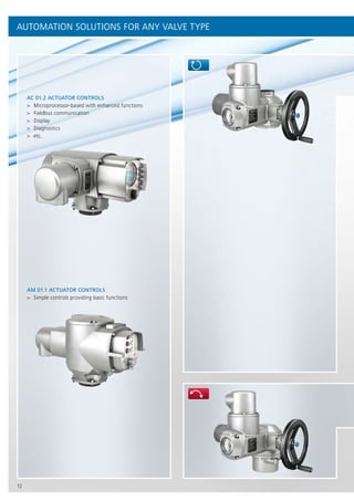
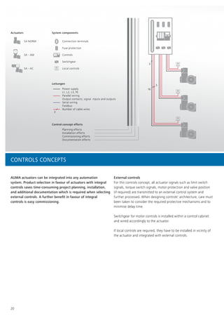
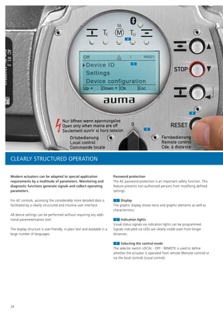
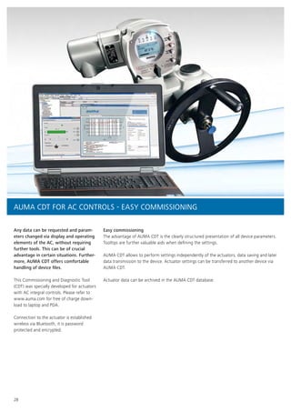
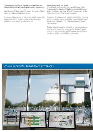
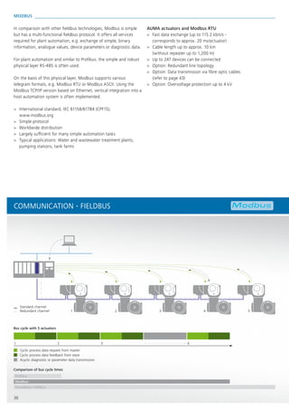
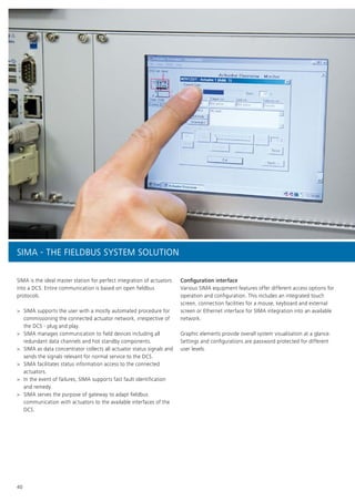
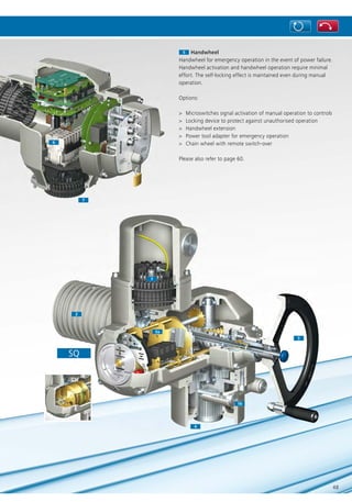
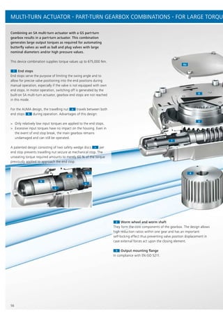
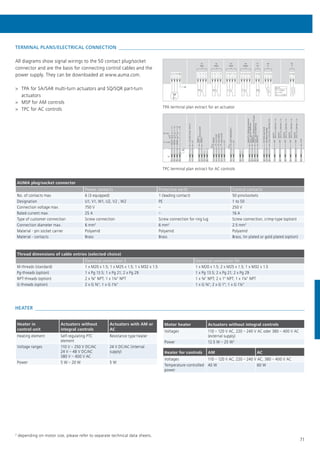
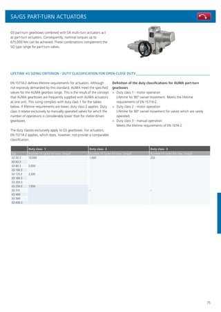
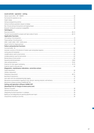
PART-TURN GEARBOXES AND PRIMARY REDUCTION GEARINGS - OPEN-CLOSE DUTY
SA/GS PART-TURN ACTUATORS
The suggested, suitable multi-turn actuators have been selected as to achieve the maximum output torque. For less demanding torque
requirements, smaller multi-turn actuators can be provided. Please refer to the separate technical data sheets for more detailed informa-
tion.
Duty class 1 - motor operation with lifetime requirements according to EN 15714-2
Type Max. output torque Valve mounting flange
Total
reduction
ratio Factor1
Input torque at
max. output
torque
Suitable multi-
turn actuator for
max. input torque
Operating time
range for 50 Hz
and 90° swing
angle
[Nm] EN ISO 5211 [Nm] [s]
GS 50.3 500 F07; F10 51:1 16.7 30 SA 07.2 9 – 191
GS 63.3 1,000 F10; F12 51:1 16.7 60 SA 07.6 9 – 191
GS 80.3 2,000 F12; F14 53:1 18.2 110 SA 10.2 9 – 199
GS 100.3 4,000 F14; F16 52:1 18.7 214 SA 14.2 9 – 195
126:1 42.8 93 SA 10.2 11 – 473
160:1 54 74 SA 10.2 13 – 600
208:1 70.7 57 SA 07.6 17 – 780
GS 125.3 8,000 F16; F25; F30 52:1 19.2 417 SA 14.6 9 – 195
126:1 44 182 SA 14.2 11 – 473
160:1 56 143 SA 14.2 13 – 600
208:1 72.7 110 SA 10.2 17 – 780
GS 160.3 14,000 F25; F30; F35 54:1 21 667 SA 16.2 9 – 203
218:1 76 184 SA 14.2 18 – 818
442:1 155 90 SA 10.2 37 – 1,658
GS 200.3 28,000 F30; F35; F40 53:1 20.7 1,353 SA 25.1 9 – 199
214:1 75 373 SA 14.6 18 – 803
434:1 152 184 SA 14.2 36 – 1,628
864:1 268 104 SA 10.2 72 – 1,6202
GS 250.3 56,000 F35; F40 52:1 20.3 2,759 SA 30.1 9 – 195
210:1 74 757 SA 16.2 35 – 788
411:1 144 389 SA 14.6 34 – 1,541
848:1 263 213 SA 14.2 71 – 1,5902
GS 315 90,000 F40; F48 53:1 23.9 3,766 SA 30.1 9 – 199
424:1 162 556 SA 14.6 35 – 1,590
848:1 325 277 SA 14.2 71 – 1,5902
1,696:1 650 138 SA 10.2 141 – 1,5902
GS 400 180,000 F48; F60 54:1 24.3 7,404 SA 35.1 9 – 203
432:1 165 1,091 SA 16.2 69 – 1,5602
864:1 331 544 SA 14.6 72 – 1,6202
1,728:1 661 272 SA 14.2 144 – 1,6202
GS 500 360,000 F60 52:1 23.4 15,385 SA 40.1 9 – 195
832:1 318 1,132 SA 16.2 69 – 1,5602
1,664:1 636 566 SA 14.6 139 – 1,5602
3,328:1 1,147 314 SA 14.2 277 – 1,5602
GS 630.3 675,000 F90/AUMA 52:1 19.8 34,160 SA 48.1 49 – 195
210:1 71.9 9,395 SA 40.1 98 – 788
425:1 145.5 4,640 SA 35.1 142 – 1,594
848:1 261.2 2,585 SA 30.1 141 – 1,5902
1,718:1 528.8 1,275 SA 25.1 286 – 1,6112
3,429:1 951.2 710 SA 16.2 286 – 1,6072
6,939:1 1,924.8 350 SA 16.2 578 – 1,6522](https://image.slidesharecdn.com/auma-electric-actuators-for-industrial-valve-automation-160831193859/85/Electric-Actuators-for-Industrial-Valve-Automation-76-320.jpg)
![77
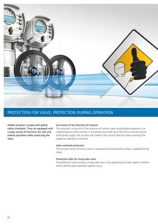
Duty class 2 - motor operation if rarely operated
Type Max. output torque Valve mounting flange
Total
reduction
ratio Factor1
Input torque at
max. output
torque
Suitable multi-
turn actuator for
max. input torque
Operating time
range for 50 Hz
and 90° swing
angle
[Nm] EN ISO 5211 [Nm] [s]
GS 50.3 625 F07; F10 51:1 16.7 37 SA 07.6 9 – 191
GS 63.3 1,250 F10; F12 51:1 16.7 75 SA 10.2 9 – 191
GS 80.3 2,200 F12; F14 53:1 18.2 120 SA 10.2 9 – 199
GS 100.3 5,000 F14; F16 52:1 18.7 267 SA 14.6 9 – 195
126:1 42.8 117 SA 10.2 11 – 473
160:1 54 93 SA 10.2 13 – 600
208:1 70.7 71 SA 10.2 17 – 780
GS 125.3 10,000 F16; F25; F30 52:1 19.2 521 SA 16.2 9 – 195
126:1 44 227 SA 14.2 11 – 473
160:1 56 179 SA 14.2 13 – 600
208:1 72.7 138 SA 14.2 17 – 780
GS 160.3 17,500 F25; F30; F35 54:1 21 833 SA 16.2 9 – 203
218:1 76 230 SA 14.2 18 – 818
442:1 155 113 SA 10.2 37 – 1,658
880:1 276 63 SA 10.2 73 – 1,6502
GS 200.3 35,000 F30; F35; F40 53:1 21.0 1,691 SA 25.1 9 – 199
214:1 75.0 467 SA 14.6 18 – 803
434:1 152 230 SA 14.2 36 – 1,628
864:1 268 131 SA 14.2 72 – 1,6202
1,752:1 552 63 SA 10.2 146 – 1,6432
GS 250.3 70,000 F35; F40; F48 52:1 20.3 3,448 SA 30.1 9 – 195
210:1 74.0 946 SA 16.2 18 – 788
411:1 144 486 SA 14.6 34 – 1,541
848:1 263 266 SA 14.6 71 – 1,5902
1,718:1 533 131 SA 14.2 143 – 1,6112
Duty class 3 - manual operation
Type Max. output torque Valve mounting flange
Total
reduction
ratio Factor
Input torque at
max. output
torque
[Nm] EN ISO 5211 [Nm]
GS 50.3 750 F07; F10 51:1 16.7 45
GS 63.3 1,500 F10; F12 51:1 16.7 90
GS 80.3 3,000 F12; F14 53:1 18.2 165
GS 100.3 6,000 F14; F16 52:1 18.7 321
126:1 42.8 140
160:1 54 111
208:1 70.7 85
GS 125.3 12,000 F16; F25; F30 126:1 44 273
160:1 56 214
208:1 72.7 165
GS 160.3 17,500 F25; F30; F35 54:1 21 833
218:1 76 230
442:1 155 113
880:1 276 63
GS 200.3 35,000 F30; F35; F40 434:1 152 230
864:1 268 131
1,752:1 552 63
GS 250.3 70,000 F35; F40; F48 848:1 263 266
1,718:1 533 131
1
Conversion factor from output torque to input torque to determine the multi-turn actuator size
2
Limited by operation mode class B (S2 - 30 min)](https://image.slidesharecdn.com/auma-electric-actuators-for-industrial-valve-automation-160831193859/85/Electric-Actuators-for-Industrial-Valve-Automation-77-320.jpg)
![78
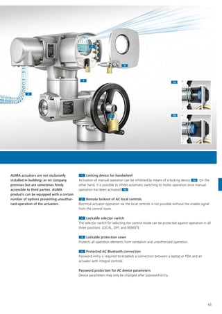
PART-TURN GEARBOXES AND PRIMARY REDUCTION GEARINGS - MODULATING DUTY
The specified torques apply for modulating duty requiring a worm wheel made of bronze. Separate specification documents are available
for other application requirements.
The suggested, suitable multi-turn actuators have been selected as to achieve the maximum output torque. For less demanding torque
requirements, smaller multi-turn actuators can be provided. Please refer to the separate technical data sheets for more detailed informa-
tion.
Type
Max. output
torque
Modulating
torque
Valve
mounting
flange
Total reduction
ratio Factor1
Input torque
at max. output
torque
Suitable
multi-turn
actuator for
max. input
torque
Operating
time range for
50 Hz and 90°
swing angle
[Nm] [Nm] EN ISO 5211 [Nm] [s]
GS 50.3 350 125 F05; F07; F10 51:1 17.9 20 SAR 07.2 9 – 191
GS 63.3 700 250 F10; F12 51:1 17.3 42 SAR 07.6 9 – 191
GS 80.3 1,400 500 F12; F14 53:1 19.3 73 SAR 10.2 9 – 199
GS 100.3 2,800 1,000 F14; F16 52:1 20.2 139 SAR 14.2 9 – 195
126:1 44.4 63 SAR 10.2 21 – 473
160:1 55.5 50 SAR 07.6 13 – 600
208:1 77 37 SAR 07.6 35 – 780
GS 125.3 5,600 2,000 F16; F25 52:1 20.8 269 SAR 14.6 9 – 195
126:1 45.4 123 SAR 14.2 21 – 473
160:1 57.9 97 SAR 10.2 27 – 600
208:1 77 73 SAR 10.2 35 – 780
GS 160.3 11,250 4,000 F25; F30 54:1 22.7 496 SAR 14.6 9 – 203
218:1 83 136 SAR 14.2 36 – 818
442:1 167 68 SAR 10.2 74 – 1,658
GS 200.3 22,500 8,000 F30; F35 53:1 22.3 1,009 SAR 25.1 72 – 199
214:1 81.3 277 SAR 14.6 36 – 803
434:1 165 137 SAR 14.2 72 – 1,628
864:1 308 73 SAR 10.2 144 – 1,6202
GS 250.3 45,000 16,000 F35; F40 52:1 21.9 2,060 SAR 30.1 71 – 195
210:1 80 563 SAR 16.2 35 – 788
411:1 156 289 SAR 14.6 69 – 1,541
848:1 305 148 SAR 14.2 141 – 1,5902
GS 315 63,000 30,000 F40; F48 53:1 26 2,432 SAR 30.1 72 – 199
424:1 178 354 SAR 14.6 71 – 1,590
848:1 356 177 SAR 14.2 141 – 1,5902
1,696:1 716 88 SAR 10.2 283 – 1,5902
GS 400 125,000 35,000 F48; F60 54:1 26.5 4,717 SAR 30.1 74 – 203
60,000 432:1 181 691 SAR 16.2 72 – 1,620
864:1 363 344 SAR 14.6 144 – 1,6202
1,728:1 726 172 SAR 14.2 288 – 1,6202
GS 500 250,000 35,000 F60 52:1 25.5 9,804 SAR 30.1 71 – 195
120,000 832:1 350 714 SAR 16.2 139 – 1,5602
1,664:1 416 358 SAR 14.6 277 – 1,5602
SWING ANGLE RANGES
Like for SQ part-turn actuators, various swing angle ranges are
available for SA/GS combinations. The ranges are independent of
gearbox sizes. Please refer to the separate data sheets for more
detailed information.
SA/GS PART-TURN ACTUATORS
1
Conversion factor from output torque to input torque to determine the
multi-turn actuator size
2
Limited by operation mode class C (S4 - 50 %)](https://image.slidesharecdn.com/auma-electric-actuators-for-industrial-valve-automation-160831193859/85/Electric-Actuators-for-Industrial-Valve-Automation-78-320.jpg)
![79
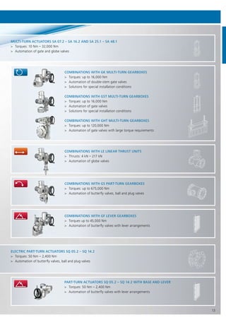
SA MULTI-TURN ACTUATORS WITH GK MULTI-TURN GEARBOXES
GK bevel gearboxes in combination with SA multi-turn actuators act
as multi-turn actuators with higher output torques. Drive shaft and
output shaft are perpendicular. Thus, this combination is particularly
appropriate for implementing special automation solutions. These
include among others particular mounting positions or simultaneous
operation of two valve stems using two GK gearboxes and a central
actuator.
The following indications serve the purpose of a rough outline. Separate data sheets are available for GK gearboxes comprising detailed
information. For further reduction ratios, please contact us.
Type
Max.
output
torque
Modulat-
ing torque Valve mounting flange
Reduction
ratios Factor Suitable multi-turn actuator
[Nm] [Nm]
EN ISO
5211 DIN 3210 Open-close duty Modulating duty
GK 10.2 120 60 F10 G0 1:1 0.9 SA 07.6; SA 10.2; SA 14.2 SAR 07.6; SAR 10.2; SAR 14.2
2:1 1.8
GK 14.2 250 120 F14 G1/2 2:1 1.8 SA 10.2; SA 14.2 SAR 10.2; SAR 14.2
2.8:1 2.5
GK 14.6 500 200 F14 G1/2 2.8:1 2.5 SA 10.2; SA 14.2 SAR 10.2; SAR 14.2
4:1 3.6
GK 16.2 1,000 400 F16 G3 4:1 3.6 SA 14.2; SA 14.6 SAR 14.2
5.6:1 5.0
GK 25.2 2,000 800 F25 G4 5.6:1 5.0 SA 14.2; SA 14.6 SAR 14.2; SAR 14.6
8:1 7.2
GK 30.2 4,000 1,600 F30 G5 8:1 7.2 SA 14.6; SA 16.2 SAR 14.6; SAR 16.2
11:1 9.9
GK 35.2 8,000 – F35 G6 11:1 9.9 SA 14.6; SA 16.2 –
16:1 14.4
GK 40.2 16,000 – F40 G7 16:1 14.4 SA 16.2; SA 25.1 –
22:1 19.8
SA/GK MULTI-TURN ACTUATORS](https://image.slidesharecdn.com/auma-electric-actuators-for-industrial-valve-automation-160831193859/85/Electric-Actuators-for-Industrial-Valve-Automation-79-320.jpg)
![80
SA MULTI-TURN ACTUATORS WITH GST MULTI-TURN GEARBOXES
GST spur gearboxes in combination with SA multi-turn actuators act
as multi-turn actuators with higher output torques. Drive shaft and
and output shaft are arranged in axial offset position. Thus, this
combination is particularly appropriate for implementing special
automation solutions. This includes among others particular
installation conditions.
The following indications serve the purpose of a rough outline. Separate data sheets are available for GST gearboxes comprising detailed
information. For further reduction ratios, please contact us.
Type
Max.
output
torque
Modulat-
ing torque Valve mounting flange
Reduction
ratios Factor Suitable multi-turn actuator
[Nm] [Nm]
EN ISO
5211 DIN 3210 Open-close duty Modulating duty
GST 10.1 120 60 F10 G0 1:1 0.9 SA 07.6; SA 10.2; SA 14.2 SAR 07.6; SAR 10.2; SAR 14.2
1.4:1 1.3
2:1 1.8
GST 14.1 250 120 F14 G1/2 1.4:1 1.3 SA 10.2; SA 14.2 SAR 10.2; SAR 14.2
2:1 1.8
2.8:1 2.5
GST 14.5 500 200 F14 G1/2 2:1 1.8 SA 10.2; SA 14.2 SAR 10.2; SAR 14.2
2.8:1 2.5
4:1 3.6
GST 16.1 1,000 400 F16 G3 2.8:1 2.5 SA 14.2; SA 14.6 SAR 14.2
4:1 3.6
5.6:1 5.0
GST 25.1 2,000 800 F25 G4 4:1 3.6 SA 14.2; SA 14.6 SAR 14.2; SAR 14.6
5.6:1 5.0
8:1 7.2
GST 30.1 4,000 1,600 F30 G5 5.6:1 5.0 SA 14.6; SA 16.2 SAR 14.6; SAR 16.2
8:1 7.2
11:1 9.9
GST 35.1 8,000 – F35 G6 8:1 7.2 SA 14.6; SA 16.2 –
11:1 9.9
16:1 14.4
GST 40.1 16,000 – F40 G7 11:1 9.9 SA 16.2; SA 25.1 –
16:1 14.4
22:1 19.8
SA/GST MULTI-TURN ACTUATORS](https://image.slidesharecdn.com/auma-electric-actuators-for-industrial-valve-automation-160831193859/85/Electric-Actuators-for-Industrial-Valve-Automation-80-320.jpg)
![81
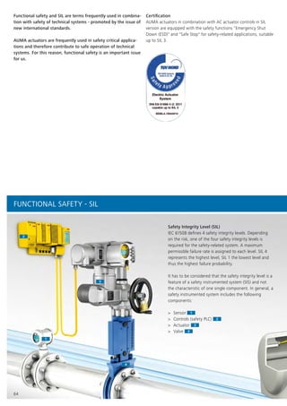
SA MULTI-TURN ACTUATORS WITH GHT MULTI-TURN GEARBOXES
GHT worm gearboxes in combination with SA multi-turn actuators
act as multi-turn actuators with high output torques. The torque
range increases nearly fourfold when combining GHT gearboxes
with SA actuators. This type of torque requirements occurs e.g. for
large gate valves, weir penstocks or dampers.
The following indications serve the purpose of a rough outline. Separate data sheets are available for GHT gearboxes comprising detailed
information. For further reduction ratios, please contact us
Type Output torque Valve mounting flange
Reduction
ratios Factor Suitable multi-turn actuator
[Nm] EN ISO 5211
GHT 320.3 32,000 F48 10:1 8 SA 30.1
15.5:1 12.4 SA 25.1
20:1 16 SA 25.1
GHT 500.3 50,000 F60 10.25:1 8.2 SA 35.1
15:1 12 SA 30.1
20.5:1 16.4 SA 30.1
GHT 800.3 80,000 F60 12:1 9.6 SA 35.1
15:1 12 SA 35.1
GHT 1200.3 120,000 F60 10.25:1 8.2 SA 40.1
20.5:1 16.4 SA 35.1
SA/GHT MULTI-TURN ACTUATORS](https://image.slidesharecdn.com/auma-electric-actuators-for-industrial-valve-automation-160831193859/85/Electric-Actuators-for-Industrial-Valve-Automation-81-320.jpg)
![82
SA MULTI-TURN ACTUATORS WITH GF LEVER GEARBOXES
SA multi-turn actuators combined with GF gearboxes act as lever
actuators.
Lever gearboxes are derived from GS part-turn gearboxes with
regard to design. Various reduction ratios are achieved by integrat-
ing primary reduction gearings.
The following indications serve the purpose of a rough outline.
Please refer to the separate data sheets for more detailed informa-
tion. Gearboxes provided for modulating applications are equipped
with a worm wheel made of bronze. The nominal torque is reduced
for this version.
Type
Max.
output
torque
Modulat-
ing torque
Total
reduction
ratio
Suitable multi-turn
actuator
[Nm] [Nm]
Open-
close duty
Modulat-
ing duty
GF 50.3 500 125 51:1 SA 07.2 SAR 07.2
GF 63.3 1,000 250 51:1 SA 07.6 SAR 07.6
GF 80.3 2,000 500 53:1 SA 10.2 SAR 10.2
GF 100.3 4,000 1,000 52:1 SA 14.2 SAR 14.2
126:1 SA 10.2 SAR 10.2
160:1 SA 10.2 SAR 07.6
208:1 SA 07.6 SAR 07.6
GF 125.3 8,000 2,000 52:1 SA 14.6 SAR 14.6
126:1 SA 14.2 SAR 14.2
160:1 SA 14.2 SAR 10.2
208:1 SA 10.2 SAR 10.2
GF 160.3 11,250 4,000 54:1 SA 16.2 SAR 14.6
218:1 SA 14.2 SAR 14.2
442:1 SA 10.2 SAR 10.2
GF 200.3 22,500 8,000 53:1 SA 25.1 SAR 25.1
214:1 SA 14.6 SAR 14.6
434:1 SA 14.2 SAR 14.2
864:1 SA 10.2 SAR 10.2
GF 250.3 45,000 16,000 52:1 SA 30.1 SAR 30.1
210:1 SA 16.2 SAR 16.2
411:1 SA 14.6 SAR 14.6
848:1 SA 14.2 SAR 14.2
SQ PART-TURN ACTUATORS WITH BASE AND LEVER
By mounting a lever and a base, the SQ actuator turns into a lever
actuator. The technical data of these lever actuators is identical to
that of the part-turn actuators, including, for example, the
maximum permissible number of starts. On the right, please find the
data for lever actuators equipped with 3-phase AC motors. Operat-
ing times apply for 90° swing angle.
SQ - open-close duty
Type
Operating
times at
50 Hz Setting range for tripping torque
[s] [Nm]
SQ 05.2 4 – 32 50 – 150
SQ 07.2 4 – 32 100 – 300
SQ 10.2 8 – 63 200 – 600
SQ 12.2 16 – 63 400 – 1,200
SQ 14.2 24 – 100 800 – 2,400
SQR - modulating duty
Type
Operating
times at
50 Hz
Setting range for
tripping torque
Permissible average
torque for modulat-
ing duty
[s] [Nm] [Nm]
SQR 05.2 8 – 32 75 – 150 75
SQR 07.2 8 – 32 150 – 300 150
SQR 10.2 11 – 63 300 – 600 300
SQR 12.2 16 – 63 600 – 1,200 600
SQR 14.2 36 – 100 1,200 – 2,400 1,200
SQ PART-TURN ACTUATORS WITH BASE AND LEVER AND SA/GF](https://image.slidesharecdn.com/auma-electric-actuators-for-industrial-valve-automation-160831193859/85/Electric-Actuators-for-Industrial-Valve-Automation-82-320.jpg)
![83
SA MULTI-TURN ACTUATORS WITH LE LINEAR THRUST UNITS
When mounting LE linear thrust units to SA multi-turn actuators,
they act as linear actuators, also referred to as linear thrust units.
The following indications serve the purpose of a rough outline.
Please refer to the separate data sheets for more detailed informa-
tion.
Type
Stroke
ranges Thrust
Suitable multi-turn
actuator
max. [mm] max. [kN]
for
modulat-
ing torque
[kN]
Open-close
duty
Modulating
duty
LE 12.1 50 11.5 6 SA 07.2 SAR 07.2
100
200
400
500
LE 25.1 50 23 12 SA 07.6 SAR 07.6
100
200
400
500
LE 50.1 63 37.5 20 SA 10.2 SAR 10.2
125
250
400
LE 70.1 63 64 30 SA 14.2 SAR 14.2
125
250
400
LE 100.1 63 128 52 SA 14.6 SAR 14.6
125
250
400
LE 200.1 63 217 87 SA 16.2 SAR 16.2
125
250
400
SA/LE LINEAR ACTUATORS](https://image.slidesharecdn.com/auma-electric-actuators-for-industrial-valve-automation-160831193859/85/Electric-Actuators-for-Industrial-Valve-Automation-83-320.jpg)

This brochure outlines the functions and applications of Auma's electric actuators for industrial valve automation, providing insights into the company's product range and technical specifications. Auma specializes in electric actuators across various sectors including energy, water, and oil & gas, offering modular solutions for valve automation. Additionally, it emphasizes the importance of reliability, service life, and safety in actuator design and operation.


