Download to read offline

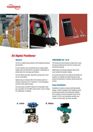
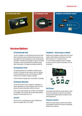
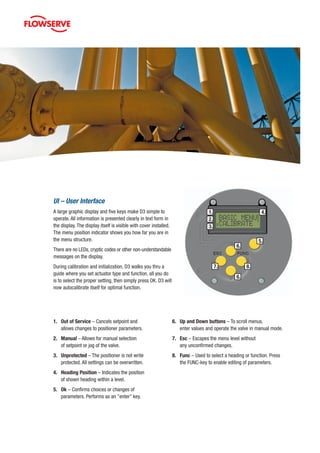
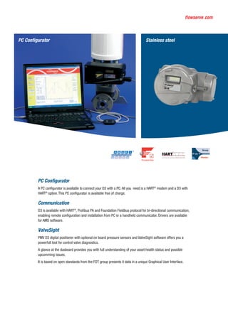


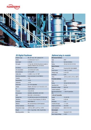
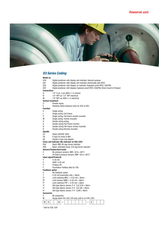

The D3 digital positioner is a user-friendly valve positioner featuring a large graphic display and low air consumption due to its zero bleed pneumatic relay. It is available in intrinsically safe, explosion-proof, and remote-mounted versions, with various optional modules for feedback and alarms, making it suitable for diverse applications. The D3 supports communication via HART, Profibus PA, or Foundation Fieldbus and is designed for easy installation and configuration.


![3 Smart Positioner [Compatibility Mode] [Repaired].ppt](https://cdn.slidesharecdn.com/ss_thumbnails/3smartpositionercompatibilitymoderepaired-250502130500-85d558d9-thumbnail.jpg?width=640&height=640&fit=bounds)


